CONTENTS PICPLC16B KEY FEATURES 4 CONNECTING THE SYSTEM 5 INTRODUCTION 6
|
|
|
- Jemimah Lorraine Curtis
- 9 years ago
- Views:
Transcription
1
2
3 CONTENTS PICPLC16B KEY FEATURES 4 CONNECTING THE SYSTEM 5 INTRODUCTION 6 Switches and Jumpers 7 MCU Ports 8 Power Supply 9 On-Board USB 2.0 Programmer 10 Power Supply Supervisor and Reset Circuit 11 Reference Voltage 12 RS-232 Communication 13 RS-485 Communication 14 On-Board Serial Ethernet 15 Optocouplers 16 Relays 18 Direct Port Access 20
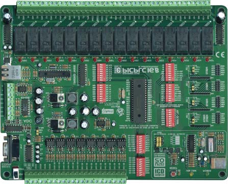
4 4 PICPLC16B KEY FEATURES 1. Power ON/OFF switch; 2. Power supply 16-30V DC or 12-22V AC; 3. Isolated power supply for optocouplers; 4. Optocouplers inputs; 5. Optocouplers; 6. DIP switches SW4 and SW5 used to enable/disable connection between optocouplers and MCU; 7. Development mode jumpers; 8. Reset push button; 9. USB connector; 10. On-board 2.0 USB programmer; 11. RS-232 communication port; 12. Reference voltage; 13. A/D converter input; 14. RS-485 communication port; 15. MCU socket with PIC18F4520 microcontroller; 16. DIP switch SW1 used to enable/disable pull-up/pulldown resistors on PORTA and PORTE pins; 17. DIP switch SW2 used to enable/disable RS232, RS-485 communication and MOSI, MISO and SCK lines; 18. DIP switch SW3 used to enable/disable Ethernet connection; 19. Direct port access connectors; 20. Ethernet communication port; 21. DIP switches SW6 and SW7 enable/disable relays; 22. Relays; 23. Relays outputs; and 24. Change over contact.
5 CONNECTING THE SYSTEM 5 Apart from this manual, the PLC (Programmable Logic Controller) system box contains PICPLC16B system, product CD, USB cable, RS232 cable and user's manual for the PICPLC16B. In order to use the PICPLC16B properly, it is necessary to go through the following steps: Step no.1 Step no.2 Step no.3 Step no.4 Take your development system and product CD out of the box. Insert the product CD into CD drive. Please, do not connect development system to PC yet. Install PICFlash2 programmer software to enable a program to be transferred from PC to the microcontroller chip. Installation instructions are con/ tained in the PICFlash 2 programmer manual. Install USB drivers on your PC to enable programmer's hardware to operate properly on the PICPLC16B board. For detailed installation instructions refer to the 'Installing USB drivers' manual. Connect the PICPLC16B to external power supply and, for programming, to PC using USB cable. Please use one of USB ports on the back of the PC because they are directly connected to the computer motherboard. The first time you switch the PICPLC16B on, your PC will automatically detect a new hardware. You will be immediately prompted whether Windows should search for new drivers update or not. Select the option 'No, not this time' and click 'Next'. Another window appears, click 'Next' and the operating system will automatically find the drivers. Click 'Finish' to complete this process and run PICFlash 2 as explained in PICFlash 2 programmer manual. Next time you switch the PICPLC16B on, Windows will not ask for new drivers update during driver installation.. CONNECTING THE SYSTEM After these four steps, your PICPLC16B is successfully installed and ready for use. You can read a program from the chip or write a new one into it. The product CD provides numerous simple program examples that will make your first steps Easy...
6 6 INTRODUCTION INTRODUCTION PICPLC16B is a programmable logic controller design to control devices in industry and automatics using relays. It has a built-in programmer so that there is no need for additional hardware for the microcontroller programming. Besides, this controller has inputs isolated by optocouplers, 12-bit A/D converter, RS-232 and RS-485 communication modules and Ethernet communication module as well. Four IDC-10 male connectors enable the PICPLC16B to be directly connected to the microcontroller pins, if needed. Figure 1 illustrates the PICPLC16B development system. As seen, there are identification marks next to each component on a silkscreen, both on the top and bottom. These marks describe connections to the microcontroller, operation modes and provide other useful information so that there is almost no need for additional schematics. Figure 1 PICPLC16B

7 SWITCHES 7 The PICPLC16B development system features a number of peripheral devices. In order to enable them before programming, the appropriate jumpers or switches have to be properly set. Switches are mechanical devices used to establish or break connection between two contacts. The PICPLC16B development system has seven groups of switches. Figure 2 Switch group SW1 Switches 1, 2, 3 and 4 are ON, whereas 5, 6, 7 and 8 are OFF DIP switch SW1 is used to enable external pull-up/pull-down resistors on PORTA and PORTE; DIP switch SW2 is used to enable/disable lines between RS-232 module (RX232 and TX232), RS-485 module (RT485, RX485 and TX485) and communication lines (MISO, MOSI and SCK); DIP switch SW3 enables Ethernet connection; DIP switches SW4 and SW5 enable/disable optocouplers inputs; and DIP switches SW6 and SW7 enable/disable connection between MCU and relays. SWITCHES AND JUMPERS JUMPERS Similarly, jumpers are used to break or establish connection between two points. Under the plastic cover of a jumper, there is a metal contact which establishes connection when the jumper is placed over two pins. Jumper is commonly used as a selector between two possible connections via 3-pin connector. As illustrated in Figure 3, the middle connector pin can be connected to the left or right pin, depending on the jumper s position. Jumper is not placed and middle pin is unconnected. Jumper is placed on the right side connecting middle and right pin. Jumper is placed on the left side connecting middle and left pin. Figure 3 Jumper as a selector

8 8 MCU PORT The PICPLC16B comes with 40-pin microcontrollers PIC18F4520 in DIP40 package. MCU PORT The microcontroller pins are routed to various peripherals. All ports are directly connected to Direct Port Access Connectors which are normally used for connecting external peripherals to the board or as points for connecting digital logic probes. Some pins are connected to other peripherals such as optocouplers, RS-232 communication, RS-485 communication, etc. Figure 4 PICPLC16B MCU Port Figure 5 System connection

9 POWER SUPPLY 9 The PICPLC16B can use two independet power supply sources. One of them is PICPLC16B board power supply and the other is isolated power supply for optocouplers. Power supply for PICPLC16B board can be AC or DC. AC power supply voltage ranges between 12 and 22V, whereas DC power supply voltage ranges between 16 and 30V. Isolated power supply for optocouplers is denoted by OCVCC on the board. Figure 6 illustrates power supply connector. POWER SUPPLY Figure 6 Power supply connector Figure 7 Power supply circuit diagram

10 10 ON-BOARD USB 2.0 PROGRAMMER ON-BOARD USB 2.0 PROGRAMMER Figure 8 USB 2.0 programmer There is no need to use external equipment during programming as the PICPLC16B development system has its own on-board USB 2.0 programmer. All you need to do is to connect the system to PC using the USB cable, enable Development MODE by setting jumpers J1, J2, J3 and J4 in the left hand position and turn the power switch on. Use the PICflash2 programming software, supplied with the board, to load a program into the microcontroller. Figure 9 USB 2.0 programmer circuit diagram

11 POWER SUPPLY SUPERVISOR AND RESET CIRCUIT 11 In industrial environment it is very important to have a reliable device capable of performing under different conditions. The most important issue for all electronic circuits is a stable power supply. However, in harsh environments there can be some deviations from the power supply nominal values. A power supply supervisor monitors power supply level and restarts the microcontroller if it is too low or too high. It can also be connected to reset button, thus generating reset signal when the button is pressed. Figure 10 Figure 11 Power supply supervisor circuit diagram Power supply supervisor POWER SUPPLY SUPERVISOR AND RESET CIRCUIT
 and Digital-to-Analog Converter (DAC) to specify input and output voltage ranges.")
12 12 VOLTAGE REFERENCE VOLTAGE REFERENCE Voltage reference is an electronic circuit that produces fixed (constant) voltage, which in our case amounts to 4.096V. It is used in both Analog-to-Digital (ADC) and Digital-to-Analog Converter (DAC) to specify input and output voltage ranges. Figure 12 Voltage Reference Figure 13 Voltage reference circuit diagram

13 RS-232 COMMUNICATION 13 RS-232 communication enables point-to-point data transfer. It is commonly used in data acquisition applications to transfer data between the microcontroller and PC. Since the voltage levels of the microcontroller and PC are not directly compatible with each other, a level converter such as MAX232 must be used. Figure 14 RS232 connector RS-232 COMMUNICATION Figure 15 RS232 circuit diagram

14 14 RS-485 COMMUNICATION RS-485 COMMUNICATION RS-485 communication enables point-to-point and point-to-multipoint data transfer. It is commonly used to enable data transfer between several microcontrollers. LTC485 interface transceiver is used for transforming signal on microcontrollers Rt, Rx and Tx lines into a differential signal on A and B lines. The PICPLC16B development board has one RS-485 communication device. In order to provide more flexible system, the microcontroller is connected to LTC485 via three switches (3,4 and 5) of DIP switch SW2. Figure 16 RS-485 communication Figure 17 RS-485 circuit diagram

15 ON-BOARD SERIAL ETHERNET 15 Ethernet is a most commonly used Local Area Network (LAN) technology today. On the top of physical layer, Ethernet stations mutually communicate by sending data packets to each other. Each station is assigned a single 48- bit MAC address which is used to specify both destination and source of each data packet. Figure 18 Ethernet connector ON-BOARD SERIAL ETHERNET Figure 19 Ethernet circuit diagram

16 16 OPTOCOUPLERS OPTOCOUPLERS The PICPLC16B has 16 optocouplers inputs. Optocouplers are widely used in industrial applications where inputs must be galvanized, i.e. electrically isolated from the rest of development board. The main idea is to protect the microcontroller from voltage spikes that might occur on input lines. Figure 20 Optocoupler group In order that input circuit is electrically isolated from the rest of board, it must have its own power supply (12V DC). The optocoupler chip has one LED on each input and one open collector transistor on each output pin. The first 8 optocoupler outputs are connected to the microcontroller PORTA and PORTE, the other 8 optocouplers outputs are connected to the microcontroller PORTC. PORTA(E) and PORTC must be driven high by putting jumpers J5 and J7 in the upper position.
17 17 OPTOCOUPLERS Figure 21 Optocoupler circuit diagram
.")
18 18 RELAYS RELAYS In order to control devices which use high power for their operation, the PICPLC16B has 16 relays connected to the microcontroller PORTB and PORTD. The relay coil voltage amounts to 12V DC (+U12). Figure 22 Relays The microcontroller PORTB and PORTD pins cannot provide enough current necessary to directly run relays and they are connected to the ULN2804 Darlington drivers, therefore. Ports RB and RD must be driven low, i.e. pulled-down, so that relays can be switched on when the microcontroller sets a logic one on any of its outputs. Each relay has one LED connected in parallel with its coil. It is used to indicate whether the appropriate relay is active or not. Reley outputs consist of three contacts: normally-open, normallyclosed and change-over, thus enabling any device to be connected to it. For example, if you connect a light bulb as per Figure 23, it will be turned on by relay activation, i.e. whenever appropriate MCU output is driven high. Figure 23 Light bulb connection
19 19 Figure 24 Relays circuit diagram RELAYS

20 20 DIRECT PORT ACCESS CONNECTORS DIRECT PORT ACCESS CONNECTORS All microcontroller input/output pins can be accessed via IDC-10 (2x5) connectors placed along the right side of the board. For each microcontroller port, there is one 10-pin connector providing up to eight port pins and two additional pins connected to VCC and GND. These connectors can be used to connect the system to external devices such as Serial Ethernet, Compact Flash, keyboard etc. If external and on-board peripherals use the same pins, then on-board peripherals must be disconnected from the microcontroller by setting the appropriate jumpers/switches. The connectors can also be used for attaching logic probes or other test equipment. Figure 25 Direct port access connectors Figure 26 Flat cable connector

21 21 DIRECT PORT ACCESS Figure 27 Direct port access circuit diagram Figure 28 PORTB connector

22 Power ON/OFF switch RS-232 module with selectable TX and RX 4.096V Voltage Reference ADC connector RS-485 module connector Ethernet connector PICPLC16B External power supply 16-30V DC 12-22V AC Power supply supervisor Optocoplers input connectors Optocouplers Reset push button USB 2.0 programmer with mikroicd Relays Relays output connectors MCU in DIP40 package USB 2.0 connector Jumpers to determine input pin performance in idle state (connected to pull-up or pull-down resistors) Direct port access
23
24
EasyPIC4 User s Manual
 SOFTWARE AND HARDWARE SOLUTIONS FOR THE EMBEDDED WORLD MikroElektronika - Books - Compilers User s Manual PIC MICROCHIP DEVELOPMENT BOARD 3in1 mikro IN-CIRCUIT DEBUGGER USB 2.0 IN-CIRCUIT PROGRAMMER With
WICE-SPI Hardware Operation Manual
 Contents 1.Hardware Instruction...1 2. Pin Definition Of WICE-SPI Connector...2 3. Peripheral Circuit Arrangements...3 4. On-Board Programming...4 5. Off-Line Programming...8 1.Hardware Instruction 1.WICE-SPI
revolution Contents: Introduction Power 28-pin Project Board with input/output cables
 28-PIN IN IN PROJECT BOARD Contents: AXE020 28-pin Project Board with input/output cables Introduction The 28-pin project board is designed to allow rapid prototyping with 28-pin PICAXE microcontrollers.
AUTOMATIC NIGHT LAMP WITH MORNING ALARM USING MICROPROCESSOR
 AUTOMATIC NIGHT LAMP WITH MORNING ALARM USING MICROPROCESSOR INTRODUCTION This Project "Automatic Night Lamp with Morning Alarm" was developed using Microprocessor. It is the Heart of the system. The sensors
KTA-223 Arduino Compatible Relay Controller
 8 Relay Outputs 5A 250VAC 4 Opto-Isolated Inputs 5-30VDC 3 Analog Inputs (10 bit) Connections via Pluggable Screw Terminals 0-5V or 0-20mA Analog Inputs, Jumper Selectable 5A Relay Switching Power Indicator
Quick Start Guide for High Voltage Solar Inverter DC-AC Board EVM. Version 1.3
 Quick Start Guide for High Voltage Solar Inverter DC-AC Board EVM Version 1.3 Introduction This document talks about the quick start principles for the high voltage solar inverter DC-AC board. From this
M68EVB908QL4 Development Board for Motorola MC68HC908QL4
 M68EVB908QL4 Development Board for Motorola MC68HC908QL4! Axiom Manufacturing 2813 Industrial Lane Garland, TX 75041 Email: [email protected] Web: http://www.axman.com! CONTENTS CAUTIONARY NOTES...3 TERMINOLOGY...3
USB to RS-422/485 Serial Adapter
 USB to RS-422/485 Serial Adapter User Manual Ver. 2.00 All brand names and trademarks are properties of their respective owners. Contents: Chapter 1: Introduction... 3 1.1 Product Introduction... 3 1.2
User s Manual of Board Microcontroller ET-MEGA2560-ADK ET-MEGA2560-ADK
 User s Manual of Board Microcontroller ET-MEGA2560-ADK ET-MEGA2560-ADK Because Arduino that is the development project on AVR MCU as Open Source has been published, it is popular and widespread shortly.
2-Port RS232/422/485 Combo Serial to USB2.0 Adapter (w/ Metal Case and Screw Lock Mechanism) Installation Guide
 Installation Guide") 2-Port RS232/422/485 Combo Serial to USB2.0 Adapter (w/ Metal Case and Screw Lock Mechanism) Installation Guide 1. Introduction Thank you for purchasing this 2-Port RS232/422/485 Combo Serial to USB Adapter.
2-Port RS232/422/485 Combo Serial to USB2.0 Adapter (w/ Metal Case and Screw Lock Mechanism) Installation Guide 1. Introduction Thank you for purchasing this 2-Port RS232/422/485 Combo Serial to USB Adapter.
User manual Compact Web PLC WP240 series IEC-line
 User manual Compact Web PLC WP240 series IEC-line update: 09-01-2014 IEC-line by OVERDIGIT overdigit.com 1. General description The WP240 device is a PLC, programmable in IEC61131-3 language using CoDeSys
ET-BASE AVR ATmega64/128
 ET-BASE AVR ATmega64/128 ET-BASE AVR ATmega64/128 which is a Board Microcontroller AVR family from ATMEL uses MCU No.ATmega64 and ATmega128 64PIN. Board ET-BASE AVR ATmega64/128 uses MCU s resources on
USER GUIDE Programming Adapter Cable for Fujitsu Flash Microcontroller- F²MC-16LX/FR Family Fujitsu Microelectronics America, Inc.
 USER GUIDE Programming Adapter Cable for Fujitsu Flash Microcontroller- F²MC-16LX/FR Family Fujitsu Microelectronics America, Inc. 1 Revision History Revision # Date Comment 1.0 03.25.2001 New Document
TCP/IP MODULE CA-ETHR-A INSTALLATION MANUAL
 TCP/IP MODULE CA-ETHR-A INSTALLATION MANUAL w w w. c d v g r o u p. c o m CA-ETHR-A: TCP/IP Module Installation Manual Page Table of Contents Introduction...5 Hardware Components... 6 Technical Specifications...
PolyBot Board. User's Guide V1.11 9/20/08
 PolyBot Board User's Guide V1.11 9/20/08 PolyBot Board v1.1 16 pin LCD connector 4-pin SPI port (can be used as digital I/O) 10 Analog inputs +5V GND GND JP_PWR 3-pin logic power jumper (short top 2 pins
EvB 5.1 v5 User s Guide
 EvB 5.1 v5 User s Guide Page 1 Contents Introduction... 4 The EvB 5.1 v5 kit... 5 Power supply...6 Programmer s connector...7 USB Port... 8 RS485 Port...9 LED's...10 Pushbuttons... 11 Potentiometers and
In-System Programmer USER MANUAL RN-ISP-UM RN-WIFLYCR-UM-.01. www.rovingnetworks.com 1
 RN-WIFLYCR-UM-.01 RN-ISP-UM In-System Programmer 2012 Roving Networks. All rights reserved. Version 1.1 1/19/2012 USER MANUAL www.rovingnetworks.com 1 OVERVIEW You use Roving Networks In-System-Programmer
Manual Serial PCI Cards
 Manual Serial PCI Cards W&T Models 13011, 13410 13411, 13610 13611, 13812 Version 1.4 Subject to error and alteration 37 01/2005 by Wiesemann & Theis GmbH Subject to errors and changes: Since we can make
DSO138 oscilloscope program upgrade method
 DSO138 oscilloscope program upgrade method Applicable models: 13801K, 13802K Program upgrade Principle The DSO138 is a SCM STM32F103C8 internal oscilloscope that is preinstalled with a flash bootloader,
ARDUINO SEVERINO SERIAL SINGLE SIDED VERSION 3 S3v3 (REVISION 2) USER MANUAL
 USER MANUAL") ARDUINO SEVERINO SERIAL SINGLE SIDED VERSION 3 S3v3 (REVISION 2) USER MANUAL X1: DE-9 serial connector Used to connect computer (or other devices) using RS-232 standard. Needs a serial cable, with at least
ARDUINO SEVERINO SERIAL SINGLE SIDED VERSION 3 S3v3 (REVISION 2) USER MANUAL X1: DE-9 serial connector Used to connect computer (or other devices) using RS-232 standard. Needs a serial cable, with at least
RS232C < - > RS485 CONVERTER S MANUAL. Model: LD15U. Phone: 91-79-4002 4896 / 97 / 98 (M) 0-98253-50221 www.interfaceproducts.info
 0-98253-50221 www.interfaceproducts.info") RS232C < - > RS485 CONVERTER S MANUAL Model: LD15U INTRODUCTION Milestone s model LD-15U is a RS232 to RS 485 converter is designed for highspeed data transmission between computer system and or peripherals
RS232C < - > RS485 CONVERTER S MANUAL Model: LD15U INTRODUCTION Milestone s model LD-15U is a RS232 to RS 485 converter is designed for highspeed data transmission between computer system and or peripherals
WinLIN Setup and Operation:
 Frequently Asked Questions about the 07551-Series Masterflex L/S Computer-Compatible drives and about the Masterflex WinLIN Linkable Instrument Control Software (07551-70) WinLIN Setup and Operation: Will
Implementing SPI Master and Slave Functionality Using the Z8 Encore! F083A
 Application Note Implementing SPI Master and Slave Functionality Using the Z8 Encore! F083A AN026701-0308 Abstract This application note demonstrates a method of implementing the Serial Peripheral Interface
CHAPTER 11: Flip Flops
 CHAPTER 11: Flip Flops In this chapter, you will be building the part of the circuit that controls the command sequencing. The required circuit must operate the counter and the memory chip. When the teach
CAN bus board. www.matrixmultimedia.com EB018
 CAN bus board www.matrixmultimedia.com EB018 Contents About this document 3 Board layout 3 General information 4 Circuit description 5 Protective cover 6 Circuit diagram 7 2 Copyright About this document
RS232 Board datasheet
 RS232 Board datasheet Contents 1. About this document 2. General information 3. Board Layout 4. Getting Started 5. Circuit Description Appendix 1 Circuit Diagram Copyright 2004 Matrix Multimedia Limited
ABB Drives. User s Manual HTL Encoder Interface FEN-31
 ABB Drives User s Manual HTL Encoder Interface FEN-31 HTL Encoder Interface FEN-31 User s Manual 3AUA0000031044 Rev B EN EFFECTIVE: 2010-04-06 2010 ABB Oy. All Rights Reserved. 5 Safety instructions
MFRD52x. Mifare Contactless Smart Card Reader Reference Design. Document information
 Rev. 2.1 17. April 2007 Preliminary Data Sheet Document information Info Keywords Content MFRC522, MFRC523, MFRC52x, MFRD522, MFRD523, Mifare Contactless Smart Card Reader Reference Design, Mifare Reader
Designing VM2 Application Boards
 Designing VM2 Application Boards This document lists some things to consider when designing a custom application board for the VM2 embedded controller. It is intended to complement the VM2 Datasheet. A
Introducing AVR Dragon
 Introducing AVR Dragon ' Front Side Back Side With the AVR Dragon, Atmel has set a new standard for low cost development tools. AVR Dragon supports all programming modes for the Atmel AVR device family.
PHYS 2P32 Project: MIDI for Arduino/ 8 Note Keyboard
 PHYS 2P32 Project: MIDI for Arduino/ 8 Note Keyboard University April 13, 2016 About Arduino: The Board Variety of models of Arduino Board (I am using Arduino Uno) Microcontroller constructd similarly
A DIY Hardware Packet Sniffer
 A DIY Hardware Packet Sniffer Affordable Penetration Testing for the Individual Veronica Swanson: University of California, Irvine CyberSecurity for the Next Generation North American Round, New York 15
PCAN-MicroMod Universal I/O Module with CAN Interface. User Manual. Document version 2.1.0 (2014-01-16)
") PCAN-MicroMod Universal I/O Module with CAN Interface User Manual Document version 2.1.0 (2014-01-16) Products taken into account Product Name Part number Model PCAN-MicroMod IPEH-002080 with firmware
PCAN-MicroMod Universal I/O Module with CAN Interface User Manual Document version 2.1.0 (2014-01-16) Products taken into account Product Name Part number Model PCAN-MicroMod IPEH-002080 with firmware
Communication with BushingGard using computer USB port
 Communication with BushingGard using computer USB port There are two ways of communication with BushingGard through computer USB port: Direct communication between computer USB port and BushingGard USB
EVAL-UFDC-1/UFDC-1M-16
 Evaluation Board for Universal Frequency-to- Digital Converters UFDC-1 and UFDC-1M-16 EVAL-UFDC-1/UFDC-1M-16 FEATURES Full-Featured Evaluation Board for the Universal Frequency-to-Digital Converters UFDC-1
Advanced Data Capture and Control Systems
 Advanced Data Capture and Control Systems Tronisoft Limited Email: [email protected] Web: www.tronisoft.com RS232 To 3.3V TTL User Guide RS232 to 3.3V TTL Signal Converter Modules P/N: 9651 Document
Fondamenti su strumenti di sviluppo per microcontrollori PIC
 Fondamenti su strumenti di sviluppo per microcontrollori PIC MPSIM ICE 2000 ICD 2 REAL ICE PICSTART Ad uso interno del corso Elettronica e Telecomunicazioni 1 2 MPLAB SIM /1 MPLAB SIM is a discrete-event
How To Use A Watt Saver On A Microcontroller (Watt Saver) On A Cell Phone Or Mp3 Player
 On A Cell Phone Or Mp3 Player") Watt Saver for a Cell Phone AC Adapter Reference Design Document Number: DRM130 Rev 1, 10/2013 2 Freescale Semiconductor, Inc. Contents Section number Title Page Chapter 1 Introduction 1.1 Overview...5
Watt Saver for a Cell Phone AC Adapter Reference Design Document Number: DRM130 Rev 1, 10/2013 2 Freescale Semiconductor, Inc. Contents Section number Title Page Chapter 1 Introduction 1.1 Overview...5
SYSTEM 45. C R H Electronics Design
 SYSTEM 45 C R H Electronics Design SYSTEM 45 All in one modular 4 axis CNC drive board By C R Harding Specifications Main PCB & Input PCB Available with up to 4 Axis X, Y, Z, & A outputs. Independent 25
PCAN-MicroMod Evaluation Test and Development Environment for the PCAN-MicroMod. User Manual. Document version 2.0.1 (2013-08-06)
") PCAN-MicroMod Evaluation Test and Development Environment for the PCAN-MicroMod User Manual Document version.0. (0-0-0) Products taken into account Product Name Part number Model PCAN-MicroMod Evaluation
PCAN-MicroMod Evaluation Test and Development Environment for the PCAN-MicroMod User Manual Document version.0. (0-0-0) Products taken into account Product Name Part number Model PCAN-MicroMod Evaluation
UniPi technical documentation REV 1.1
 technical documentation REV 1.1 Contents Overview... 2 Description... 3 GPIO port map... 4 Power Requirements... 5 Connecting Raspberry Pi to UniPi... 5 Building blocks... 5 Relays... 5 Digital Inputs...
SYSTEM 4C. C R H Electronics Design
 SYSTEM 4C C R H Electronics Design SYSTEM 4C All in one modular 4 axis CNC drive board By C R Harding Specifications Main PCB & Input PCB Available with up to 4 Axis X, Y, Z, A outputs. Independent 25
GSM Interfacing Board
 Campus Component Pvt. Ltd. DISCLAIMER Information furnished is believed to be accurate and reliable at the time of publication. However, Campus Component Pvt. Ltd. assumes no responsibility arising from
STK500... User Guide
 STK500... User Guide Table of Contents Section 1 Introduction... 1-1 1.1 Starter Kit Features...1-1 1.2 Device Support...1-2 Section 2 Getting Started... 2-1 2.1 Unpacking the System...2-1 2.2 System
DK40 Datasheet & Hardware manual Version 2
 DK40 Datasheet & Hardware manual Version 2 IPC@CHIP DK40 Evaluation module Beck IPC GmbH http://www.bcl.de page 1 of 11 Table of contents Table of contents... 2 Basic description... 3 Characteristics...
STEPPER MOTOR SPEED AND POSITION CONTROL
 STEPPER MOTOR SPEED AND POSITION CONTROL Group 8: Subash Anigandla Hemanth Rachakonda Bala Subramanyam Yannam Sri Divya Krovvidi Instructor: Dr. Jens - Peter Kaps ECE 511 Microprocessors Fall Semester
How to read this guide
 How to read this guide The following shows the symbols used in this Quick start guide with descriptions and examples. Symbol Description Example P oint Reference Caution [ ] This symbol explains information
How To Program A Microcontroller Board (Eb064) With A Psp Microcontroller (B064-74) With An Ios 2.5V (Power) And A Ppt (Power Control) (Power Supply) (
 With A Psp Microcontroller (B064-74) With An Ios 2.5V (Power) And A Ppt (Power Control) (Power Supply) (") dspic / PIC24 Multiprogrammer datasheet EB064-00 00-1 Contents 1. About this document... 2 2. General information... 3 3. Board layout... 4 4. Testing this product... 5 5. Circuit description... 6 Appendix
dspic / PIC24 Multiprogrammer datasheet EB064-00 00-1 Contents 1. About this document... 2 2. General information... 3 3. Board layout... 4 4. Testing this product... 5 5. Circuit description... 6 Appendix
BIT COMMANDER. Serial RS232 / RS485 to Ethernet Converter
 BIT COMMANDER Serial RS232 / RS485 to Ethernet Converter (Part US2000A) Copyrights U.S. Converters 1 Contents Overview and Features... 3 Functions..5 TCP Server Mode... 5 Httpd Client Mode.5 TCP Auto mode....6
WIZ-Embedded WebServer User s Manual (Ver. 1.0)
") [텍스트 입력] WIZ-Embedded WebServer User s Manual (Ver. 1.0) 2007 WIZnet Inc. All Rights Reserved. For more information, visit our website at www.wiznet.co.kr Document History Information Revision Data Description
[텍스트 입력] WIZ-Embedded WebServer User s Manual (Ver. 1.0) 2007 WIZnet Inc. All Rights Reserved. For more information, visit our website at www.wiznet.co.kr Document History Information Revision Data Description
USB I/O CONTROL BOX 8 relays, 8 digital I/O lines and 8 HV inputs
 USB I/O CONTROL BOX 8 relays, 8 digital I/O lines and 8 HV inputs The Big Deal USB HID device compatible with 32/64 Bit operating systems 8 TTL/LVTTL digital I/O channels, 8 High Voltage digital inputs
EZmoto V2. Product description Rev. 6 10/01/2014. EZmoto V2 Product description Rev.6 10/01/2014
 EZmoto V2 Product description Rev. 6 10/01/2014 1 Contents 1. Overview... 3 2. Hardware Interface Description... 3 2.1 Main features of the EZmoto... 3 2.2 Hardware block diagram... 4 2.3 Internal Hardware
RC2200DK Demonstration Kit User Manual
 Demonstration Kit User Manual Table of contents TABLE OF CONTENTS... 1 QUICK INTRODUCTION... 2 INTRODUCTION... 3 DEMONSTRATION BOARD... 4 POWER SUPPLY SECTION... 5 RS-232 INTERFACE... 6 CONNECTORS... 7
Antenna Rotator System
 Antenna Rotator System RCI-USB Reference Manual September/2011 Rev 1.3c Introduction Thank you for purchasing the ARS RCI-USB Interface. Presently, the ARS System provides the most powerful highest performance
Software User Guide UG-461
 Software User Guide UG-461 One Technology Way P.O. Box 9106 Norwood, MA 02062-9106, U.S.A. Tel: 781.329.4700 Fax: 781.461.3113 www.analog.com ezlinx icoupler Isolated Interface Development Environment
AN-812 APPLICATION NOTE
 AN- APPLICATION NOTE One Technology Way P.O. Box 90 Norwood, MA 00-90, U.S.A. Tel: 7.9.700 Fax: 7.. www.analog.com Microcontroller-Based Serial Port Interface (SPI ) Boot Circuit by Alfredo Barriga INTRODUCTION
(USR-TCP232-T, USR-TCP232-2) (USR-TCP232-S, USR-TCP232-D) (USR-TCP232-24, USR-TCP232-200) (USR-TCP232-300, USR-TCP232-442) File version: V3.
 (USR-TCP232-S, USR-TCP232-D) (USR-TCP232-24, USR-TCP232-200) (USR-TCP232-300, USR-TCP232-442) File version: V3.") Serial to Ethernet module user manual Serial to Ethernet module (USR-TCP232-T, USR-TCP232-2) (USR-TCP232-S, USR-TCP232-D) (USR-TCP232-24, USR-TCP232-200) (USR-TCP232-300, USR-TCP232-442) File version:
Serial to Ethernet module user manual Serial to Ethernet module (USR-TCP232-T, USR-TCP232-2) (USR-TCP232-S, USR-TCP232-D) (USR-TCP232-24, USR-TCP232-200) (USR-TCP232-300, USR-TCP232-442) File version:
AC-PG-USBASP USBASP AVR Programmer
 AC-PG-USBASP-UG TABLE OF CONTENTS 1. OVERVIEW... 1 1.1. Introduction... 1 1.2. References... 1 1.2.1. Referenced Web Pages... 1 1.2.2. Acronyms and Abbreviations... 1 1.3. Supported Microcontrollers...
RGB for ZX Spectrum 128, +2, +2A, +3
 RGB for ZX Spectrum 128, +2, +2A, +3 Introduction... 2 Video Circuitry... 3 Audio Circuitry... 8 Lead Wiring... 9 Testing The Lead... 11 Spectrum +2A/+3 RGB Differences... 12 Circuitry Calculations...
Testing Data Radio Modem with Serial Port Tool V1.20
 Testing Data Radio Modem with Serial Port Tool V1.20 This document demonstrates how to test the communication of data radio modem with tool Advanced Serial Port Monitor from AGG Software and USB board.
POCKET SCOPE 2. The idea 2. Design criteria 3
 POCKET SCOPE 2 The idea 2 Design criteria 3 Microcontroller requirements 3 The microcontroller must have speed. 3 The microcontroller must have RAM. 3 The microcontroller must have secure Flash. 3 The
TPM Product Type 107-D162-NNT 48-channel digital input and 16-channel digital output module with pluggable terminal
 Product Type 107-D162-NNT 48-channel digital input and 16-channel digital output module with pluggable terminal Specifications Size: (L122 x W123 x H104 mm) Series Interface: Half duplex RS-485 with transformer
NEC USB PortBar with the Driver Installation Diskette
 NEC USB PortBar with the Driver Installation Diskette Congratulations on purchasing the NEC USB PortBar for your NEC Versa notebook computer! The NEC USB PortBar connects to the USB port on your NEC Versa
Pmod peripheral modules are powered by the host via the interface s power and ground pins.
 Digilent Pmod Interface Specification Revision: November 20, 2011 1300 NE Henley Court, Suite 3 Pullman, WA 99163 (509) 334 6306 Voice (509) 334 6300 Fax Introduction The Digilent Pmod interface is used
Eliminate Risk of Contention and Data Corruption in RS-485 Communications
 I. Background and Objective Eliminate Risk of Contention and Data Corruption in RS-485 Communications Earle Foster, Jeff Hunter Sealevel Systems The RS-485 communications standard was introduced in 1983
Bluetooth HC-06 with serial port module Easy guide
 1 Bluetooth HC-06 with serial port module Easy guide This manual consists of 3 parts: PART 1. Overview of Bluetooth HC-06 module with serial port. PART 2. Installing Bluetooth HC-06 module with Bolt 18F2550
Real Time Clock USB Evaluation Board V3.0
 Real Time Clock USB Evaluation Board V.0 Application Note February 9, 008 RTC EVB Intersil RTC Devices Supported Introduction This evaluation board provides a platform for testing Intersil Real Time Clock
INDEX. Trademarks All name and product s trademarks mentioned below are the property of their respective companies.
 USB2.0 EASY IDE ADAPTER INDEX Trademarks ---------------------------------------------------------------------------- Introduction ---------------------------------------------------------------------------
Digital I/O: OUTPUT: Basic, Count, Count+, Smart+
 Digital I/O: OUTPUT: Basic, Count, Count+, Smart+ The digital I/O option port in the 4-Series provides us with 4 optically isolated inputs and 4 optically isolated outputs. All power is supplied externally.
TURBO PROGRAMMER USB, MMC, SIM DEVELOPMENT KIT
 TURBO PROGRAMMER USB, MMC, SIM DEVELOPMENT KIT HARDWARE GUIDE This document is part of Turbo Programmer documentation. For Developer Documentation, Applications and Examples, see http:/// PRELIMINARY (C)
The Programming Interface
 : In-System Programming Features Program any AVR MCU In-System Reprogram both data Flash and parameter EEPROM memories Eliminate sockets Simple -wire SPI programming interface Introduction In-System programming
An Introduction to MPLAB Integrated Development Environment
 An Introduction to MPLAB Integrated Development Environment 2004 Microchip Technology Incorporated An introduction to MPLAB Integrated Development Environment Slide 1 This seminar is an introduction to
PM1122 INT DIGITAL INTERFACE REMOTE
 PM1122 INT DIGITAL INTERFACE REMOTE PM1122 INT front panel description: 1. Clear wireless remotes knob: push this button for more than 2 seconds to clear the list of all assigned wireless remote settings
Elettronica dei Sistemi Digitali Costantino Giaconia SERIAL I/O COMMON PROTOCOLS
 SERIAL I/O COMMON PROTOCOLS RS-232 Fundamentals What is RS-232 RS-232 is a popular communications interface for connecting modems and data acquisition devices (i.e. GPS receivers, electronic balances,
Lab Experiment 1: The LPC 2148 Education Board
 Lab Experiment 1: The LPC 2148 Education Board 1 Introduction The aim of this course ECE 425L is to help you understand and utilize the functionalities of ARM7TDMI LPC2148 microcontroller. To do that,
Data Sheet. Adaptive Design ltd. Arduino Dual L6470 Stepper Motor Shield V1.0. 20 th November 2012. L6470 Stepper Motor Shield
 Arduino Dual L6470 Stepper Motor Shield Data Sheet Adaptive Design ltd V1.0 20 th November 2012 Adaptive Design ltd. Page 1 General Description The Arduino stepper motor shield is based on L6470 microstepping
USR-TCP232-T Hard Version: V2.0 Doc Version: V1.1 2011-08-16
 RS232 Serial TO Ethernet convert Module USR-TCP232-T Hard Version: V2.0 Doc Version: V1.1 2011-08-16 Jinan USR Technology Co., Ltd. works on LAN and WAN and wireless for MCU to Ethernet Solutions, Ethernet,
LEN s.r.l. Via S. Andrea di Rovereto 33 c.s. 16043 CHIAVARI (GE) Tel. +39 0185 318444 - Fax +39 0185 472835 mailto: [email protected] url: http//www.len.
 Tel. +39 0185 318444 - Fax +39 0185 472835 mailto: len@len.it url: http//www.len.") MA511 General Index 1 INTRODUCTION... 3 1.1 HARDWARE FEATURES:... 4 2 INTERFACE... 5 2.1 KEYBOARD... 6 2.2 POWER ON... 7 2.3 POWER OFF... 7 2.4 DETECTOR CONNECTION... 7 2.5 DETECTOR SUBSTITUTION...7 3
MA511 General Index 1 INTRODUCTION... 3 1.1 HARDWARE FEATURES:... 4 2 INTERFACE... 5 2.1 KEYBOARD... 6 2.2 POWER ON... 7 2.3 POWER OFF... 7 2.4 DETECTOR CONNECTION... 7 2.5 DETECTOR SUBSTITUTION...7 3
INTRODUCTION FEATURES OF THE ICM
 INTRODUCTION The ICM, Internet Control Module, is a remote controller device accessible via the Internet that allows operational access to the IPS (and other base units available). Through the ICM you
ezsystem elab16m Project 1F: Alarm System (Full Project description)
") ezsystem elab16m Project 1F: Alarm System (Full Project description) ezsystem The aim of ezsystem is to enable Creativity and Innovation at an early age in a Problem Based Learning (PBL) approach. ezsystem
ezsystem elab16m Project 1F: Alarm System (Full Project description) ezsystem The aim of ezsystem is to enable Creativity and Innovation at an early age in a Problem Based Learning (PBL) approach. ezsystem
GPS/GLONASS SiRFstarV Evaluation Kit EVA5100-A
 GPS/GLONASS SiRFstarV Evaluation Kit EVA5100-A A Description of the Evaluation Board for Maestro s GPS/GLONASS Receiver Module A5100-A User s Manual Version 0.1 Revision History Rev. Date Description 0.1
Data Acquisition Module with I2C interface «I2C-FLEXEL» User s Guide
 Data Acquisition Module with I2C interface «I2C-FLEXEL» User s Guide Sensors LCD Real Time Clock/ Calendar DC Motors Buzzer LED dimming Relay control I2C-FLEXEL PS2 Keyboards Servo Motors IR Remote Control
RS-422/485 Multiport Serial PCI Card. RS-422/485 Multiport Serial PCI Card Installation Guide
 RS-422/485 Multiport Serial PCI Card Installation Guide 21 Contents 1. Introduction...1 2. Package Check List...2 3. Board Layouts and Connectors...3 3.1 2S with DB9 Male Connectors...3 3.1.1 JP5: UART
A+ Guide to Managing and Maintaining Your PC, 7e. Chapter 1 Introducing Hardware
 A+ Guide to Managing and Maintaining Your PC, 7e Chapter 1 Introducing Hardware Objectives Learn that a computer requires both hardware and software to work Learn about the many different hardware components
Serial Communications
 April 2014 7 Serial Communications Objectives - To be familiar with the USART (RS-232) protocol. - To be able to transfer data from PIC-PC, PC-PIC and PIC-PIC. - To test serial communications with virtual
NC-12 Modbus Application
 NC-12 Modbus Application NC-12 1 Table of Contents 1 Table of Contents... 2 2 Glossary... 3 SCADA...3 3 NC-12 Modbus in general... 3 4 Entire system... 4 4.1 PFC to PC connection alternatives...4 4.1.1
40-Segment 2.54 pitch LED Bar Display Board User s Guide
 Sure Electronics 0-Segment. pitch LED Bar Display Board User s Guide Product Name Product ID : 0-segment.mm pitch LED Bar Display Board : DE-DP0 Product Version : Ver.0 Document Version : Ver.0 Copyright
TEST CHAPTERS 1 & 2 OPERATING SYSTEMS
 TEST CHAPTERS 1 & 2 OPERATING SYSTEMS True/False Indicate whether the statement is true or false. 1. Changes that you make in virtual machines do not affect your physical computer. 2. The size of a bus
FlowKit in-circuit debug system
 FlowKit in-circuit debug system www.matrixmultimedia.com HP299 Contents About this document 3 Board layout 3 General information 4 Detailed operation 4 Circuit diagram 7 2 Copyright About this document
Programming Logic controllers
 Programming Logic controllers Programmable Logic Controller (PLC) is a microprocessor based system that uses programmable memory to store instructions and implement functions such as logic, sequencing,
How to connect to a Class II router using a mobile-phone data cable specifically for Solwise & Safecom routers
 USB to router s serial port How to connect to a Class II router using a mobile-phone data cable specifically for Solwise & Safecom routers by Neo at RouterTech.Org Introduction Routers based on the AR7RD/AR7WRD
1-10 The USB PIC K150 microcontroller programmer Hardware version V2.0 File version V2.0 Product Image
 1-10 The USB PIC K150 microcontroller programmer Hardware version V2.0 File version V2.0 Product Image 2-10 Product Description: K150 is the latest of a low-cost high-performance PIC programmer, support
The RIDZ 8x2 Audio Switcher
 The RIDZ 8x2 Audio Switcher Engineering Manual Support Number 800-765-2930 International 712-852-2813 Table of Contents General Information for the RIDZ (8 x 2) Switcher..... 3 Input 9 on the RIDZ Switcher....6
16-Port RS232 to USB2.0 High Speed Multi Serial Adapter (w/ Metal Case) Installation Guide
 Installation Guide") 16-Port RS232 to USB2.0 High Speed Multi Serial Adapter (w/ Metal Case) Installation Guide 1. Introduction Thank you for purchasing this 16-Port RS232 to USB2.0 High Speed Multi Serial Adapter. It is an
16-Port RS232 to USB2.0 High Speed Multi Serial Adapter (w/ Metal Case) Installation Guide 1. Introduction Thank you for purchasing this 16-Port RS232 to USB2.0 High Speed Multi Serial Adapter. It is an
Options for ABB drives, converters and inverters. User s manual FDPI-02 diagnostics and panel interface
 Options for ABB drives, converters and inverters User s manual FDPI-02 diagnostics and panel interface Table of contents Table of contents 3 1. FDPI-02 diagnostics and panel interface Safety..............................................
STIM202 Evaluation Kit
 Table of contents: 1 FEATURES... 2 2 GENERAL DESCRIPTIONS AND SYSTEM CONTENTS... 2 3 SYSTEM REQUIREMENTS... 2 4 GETTING STARTED... 3 4.1 INSTALLATION OF NI-SERIAL CABLE ASSEMBLY DRIVER... 3 4.2 INSTALLATION
User Manual IC-485AI 2002-09-27
 User Manual IC-485AI Note: This equipment has been tested and found to comply ith the limits for a Class A digital device pursuant to Part 15 of the FCC Rules. These limits are designed to provide reasonable
Single channel data transceiver module WIZ2-434
 Single channel data transceiver module WIZ2-434 Available models: WIZ2-434-RS: data input by RS232 (±12V) logic, 9-15V supply WIZ2-434-RSB: same as above, but in a plastic shell. The WIZ2-434-x modules
PU-USBX. USB over Ethernet Extender OPERATION MANUAL
 PU-USBX USB over Ethernet Extender OPERATION MANUAL Safety Precautions Please read all instructions before attempting to unpack or install or operate this equipment, and before connecting the power supply.
Orbit PCI Mk 2 Network Card. User Manual. Part No. 502566 Issue 4
 Orbit PCI Mk 2 Network Card User Manual Part No. 502566 Issue 4 Information in this document is subject to change without notice. Companies, names and data used in examples herein are fictitious unless