Professional Power Amplifier. User Manual
|
|
|
- Tabitha Benson
- 10 years ago
- Views:
Transcription
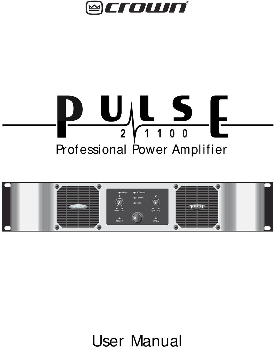
1 Professional Power Amplifier User Manual
2 Contents Safety Information Introduction & Unpacking Mechanical Installation AC Power Connection Audio Connections... 7 Inputs... 7 Outputs... 8 Stereo operation... 8 Bridge mono operation Control operation... 9 a. Power Switch... 9 b. Level controls 1 and c. Bridge switch Indicators A. AC Present B. Operate C. Fault D. Temp 1& E. Signal F. Clip G. Bridge Typical applications a. Two channel (stereo) operation b. Two amplifiers used in bridge mode c. Two amplifiers for stereo with a mono sub-bass d. Calculating Impedance Glossary Specifications Troubleshooting Checklist Status Indication Service & Warranty

3 Safety Information Important Safety Instructions 1) Read these instructions. 2) Keep these instructions. 3) Heed all warnings. 4) Follow all instructions. 5) Do not use this apparatus near water. 6) Clean only with a dry cloth. 7) Do not block any ventilation openings. Install in accordance with the manufacturer s instructions. 8) Do not install near any heat sources such as radiators, heat registers, stoves, or other apparatus that produce heat. 9) Do not defeat the safety purpose of the polarized or grounding-type plug. A polarized plug has two blades with one wider than the other. A grounding-type plug has two blades and a third grounding prong. The wide blade or the third prong is provided for your safety. If the provided plug does not fit into your outlet, consult an electrician for replacement of the obsolete outlet. 10) Protect the power cord from being walked on or pinched, particularly at plugs, convenience receptacles, and the point where they exit from the apparatus. 11) Only use attachments/accessories specified by the manufacturer. 12) Use only with a cart, stand, bracket, or table specified by the manufacturer, or sold with the apparatus. When a cart is used, use caution when moving the cart/ apparatus combination to avoid injury from tip-over. 13) Unplug this apparatus during lightning storms or when unused for long periods of time. 14) Refer all servicing to qualified service personnel. Servicing is required when the apparatus has been damaged in any way, such as power-supply cord or plug is damaged, liquid has been spilled or objects have fallen into the apparatus, the apparatus has been exposed to rain or moisture, does not operate normally, or has been dropped. DO NOT REMOVE COVERS. NO USER SERVICEABLE PARTS INSIDE. REFER SERVICING TO QUALIFIED SERVICE PERSONNEL. THIS EQUIPMENT MUST BE GROUNDED. IT SHOULD NOT BE NECESSARY TO REMOVE ANY PROTECTIVE GROUND OR SIGNAL CABLE SHIELD CONNECTIONS TO PREVENT GROUND LOOPS. ANY SUCH DISCONNECTIONS ARE OUTSIDE THE RECOMMENDED PRACTICE OF CROWN AND WILL RENDER ANY EMC OR SAFETY CERTIFICATION VOID. For continued compliance with international EMC legislation ensure that all input cables are wired with the cable screen connected to Pin 1 of the XLR connectors and/or the jack plug sleeve. WARNING! This equipment can create high sound levels. Exposure without adequate protection could cause permanent damage to hearing. This equipment has been tested and found to comply with the following European and international Standards for Electromagnetic Compatibility and Electrical Safety: Radiated Emissions (EU): EN55013 (1990) Associated Equipment RF Immunity (EU): EN50082/1 (1992) RF Immunity, Fast Transients & ESD Mains Disturbance (EU): EN61000/3/2 (1995) Electrical Safety (EU): EN60065 (1993) Radiated Emissions (USA): FCC part 15 Class B 3

4 1.0 Introduction & Unpacking Front panel Rear panel Introduction The PULSE series of amplifiers are high performance professional power amplifiers capable of delivering major power output from a new generation of switched mode power supplies. All Pulse series amplifiers are housed in the same size 2U cases and feature light, powerful switching power supplies along with massive heatsinks and two dual-speed cooling fans. Microprocessor supervision of the power supplies, protection and thermal systems, ensures that the amplifier is always operating correctly thereby protecting both the amplifier and your speakers from failure. We set out to design an amplifier that is as equally at home in live touring sound environments as it is for installation amplification. We especially wanted to produce amplifiers that are capable of maintaining excellent performance when being driven to their limit with real loudspeaker loads. Sonic performance is always in the forefront of our minds and to this end the PULSE series represents the pinnacle of many years work with professional amplifiers. PULSE amplifiers have impeccable technical specifications, and extensive listening tests by many people with a wide variety of loudspeakers leads us to believe that they sound pretty good too! Unpacking As part of the Crown system of quality control, we check every product carefully before packing to ensure that it reaches you in flawless condition. Before you go any further, please check the unit for any physical damage and retain the shipping carton and all relevant packing materials for use, should the unit need returning. In the event that damage has occurred, please notify your dealer immediately, so that a written claim to cover the damages can be initiated. Check out the Service and Warranty section for more information. 4

5 2.0 Mechanical Installation A vertical rack space of 2U (88mm high) is required, with an in rack depth of 18.1 inches (460mm). The amplifier protrudes 1.6 inches (40mm) from the rack supports. Mounting & unit dimensions If the unit is likely to undergo extreme vibration through trucking and touring, front rack ear reinforcement brackets and rear mounting plates must be fitted. These are available from your dealer. Damage caused by insufficient support is not covered by the warranty. To prevent damage to the front panel finish, always use protective plastic cups or washers underneath the rack mounting bolts. Ventilation gaps between units are not required, however care must be taken to ensure that an unobstructed free flow of clean air is possible from the back of the unit to the front. It is important that neither the rear air intakes or front exhaust grilles are covered. The internal airflow of all PULSE amplifiers is designed to minimize contamination of the electronics by the cooling air so fan filters will not normally be required. If however, the amplifier is to be used in an environment where the intake air might be excessively dirty, optional external fan filters should be purchased from your dealer. Fan filters should NOT be fitted unless there is likely to be a problem as they require regular cleaning to stop them getting clogged. Clogged fan filters will result in the amplifier going into premature temperature protect. PLEASE NOTE: Users must ensure that glycol based smoke and related substances are not allowed to enter the amplifier (fan filters will not help). Glycol based smoke is HIGHLY corrosive and prolonged exposure will cause irreparable damage to your amplifier. Do not expose the amplifier to rain or moisture during either operation or storage. If the unit does come into contact with moisture, remove the AC power cord immediately and leave it in a suitably dry, warm place to dry out. Be aware that when any equipment is taken from a cold location into a hot humid one, condensation may occur inside. Always allow time for the equipment to attain the same temperature as its environment before applying the AC power cord. 5

6 3.0 AC Power Connection WARNING! THIS APPLIANCE MUST BE GROUNDED. The amplifier must always be connected to a 3-wire grounded AC outlet. The rack framework must also be connected to the same grounding circuit. The unit must NOT be operated unless the power cables' ground wire is properly terminated - this is important for personal safety as well as for proper control over the system grounding. The wires in the power lead are color coded as follows: Green and Yellow...Ground Blue...Neutral Brown...Live/Hot IMPORTANT: The PULSE 2x1100 is designed to use 50/60Hz AC power. Acceptable AC input supply voltage ranges from 180V to 265V The application of voltages above those specified may cause permanent damage that is not covered by your warranty. Lower voltages may cause erratic operation. Note that although the amplifier will operate correctly down to the voltages indicated, the quoted output power will only be achieved with the stated nominal voltages. IMPORTANT : The AC power fuse carrier on the rear of the unit must be fitted with the correct type and rating of fuse, in this case T10A. In the unlikely event of the AC fuse failing without good reason, disconnect the unit from the power supply, and always replace with the appropriately rated fuse (as specified above) for continued protection against damage and fire. 6

7 4.0 Audio Connections Inputs For each channel, there is a 1/4 phone jack socket, male & female XLR and pluggable removable terminal block connectors provided for signal input on the rear panel of the amplifier. Each is electronically balanced at an impedance greater than 10k ohms. The removable terminal block, phone jack and both XLR connectors are internally wired in parallel, and therefore any socket may be used for the input signal. The connectors not used in this manner function as loop-through connectors for daisy chaining a number of channels. The HOT, + or in phase connection for the removable terminal block is to pin 2 of the XLRs and the TIP of the phone jack. The COLD, -, or out of phase connection for the removable terminal block is to pin 3 of the XLRs and the phone jack RING. The removable terminal block earth symbol pin, pin 1 of the XLR s and the phone jack SLEEVE are internally connected to the chassis. The screen of the input cable should always be connected to one of these points to ensure that EMC regulations are met. The cable shield ground should also be connected to the equipment which is providing the input signal. balanced wiring to pulse XLR balanced wiring to pulse phone jack When feeding the PULSE 2x1100 from unbalanced sources, connect the signal conductor to the + pin of the removable terminal block, pin 2 of the XLR or the phone jack TIP, with the cable screen going to pins - and ground of the removable terminal block, 1 and 3 of the XLRs or the SLEEVE and RING of the phone jack. Unbalanced wiring to pulse XLR Unbalanced wiring to pulse phone jack For bridge mode operation, channel 1 is used as the input signal for the amplifier. The channel 2 input is ignored when bridge mode is enabled. 7

8 Audio Connections... Outputs Both binding post and Speakon connectors are provided for each channel, these are internally wired in parallel so either or both may be used. Note that it is possible to lever the caps out of the ends of the binding posts to insert 4mm banana type plugs but this will invalidate the product safety approvals in some territories. The side entry positions for these connectors should therefore be used if possible. Stereo wiring Stereo operation If you are using the binding posts, for non bridged operation the loudspeakers should be connected between the RED and BLACK binding post terminals or the Speakon 1+ & 1- pins. The amplifier will be noninverting with respect to the RED terminal and 1+ Speakon pin More than one speaker can be connected to each channel as long as the total impedance per channel is not less that 2 ohms. See section 7.0d of this manual for more information about how to calculate impedance. Bridge wiring 1-1+ Do NOT connect Do NOT connect Bridge mono operation To use the amplifier in bridge mode, for binding post connection, the speakers must be connected between two RED terminals leaving the BLACK terminals unconnected. In bridge mode the amplifier is noninverting relative to the 1+ pin of the Speakon connector and the channel 1 RED binding post. If the Speakon connector is used, switching the amplifier in to bridge automatically takes care of the Speakon wiring for you. Therefore the loudspeaker connector is WIRED THE SAME WAY AS FOR NON BRIDGE MODE, i.e. between 1+ and 1-. This significantly simplifies the speaker wiring enabling the same leads to be used for bridged and non-bridged modes. Channel 1 output carries the bridged signal. During bridge mode operation no connector should be inserted into the channel 2 output. More than one speaker can be connected to the bridged pair of channels as long as the total impedance is not less that 4 ohms. See section 7.0d of this manual for more information about how to calculate impedance. 8

9 5.0 Control operation a. Power Switch Pressing this switch so that the white dot is closest to the front panel signals to the microprocessor that the user wishes to turn on the power supply. Note that the microprocessor will only switch the power supply on once it has assured that there are no internal faults. From the first application of AC power it takes approximately 7 seconds to complete these tests. During the test time the microprocessor will flash both the TEMP lights and the FAULT light once a second. If the amplifier has already completed these tests, then when the switch is pressed, power up will occur within 1 second. While the power up sequence is being completed all amplifiers channels are muted. b. Level controls 1 and 2 These controls allow the user to change the sensitivity, or the level required to drive each channel of the amplifier into clip, from approximately +90dBu with the controls fully counter clockwise, to +1dBu with the controls full clockwise. +1dBu equals approximately 870mV RMS and this level will be just sufficient with a 4 Ohm load and nominal AC voltage to drive the amplifier into clip. If the amplifier is operated in bridge mode, use the channel 1 level control only, the channel 2 control has no effect. Supplied with each PULSE amplifier are special blanking plugs that may be fitted after the control knobs have been pulled off thus allowing the levels to be set and then made tamper proof. c. Bridge switch Located on the rear panel, this switch enables bridge mode operation. Activation of this switch is indicated by the Bridge indicator on the front panel. When the amplifier is operated in bridge mode, the power available doubles allowing larger speakers to be driven. Two things must be kept in mind when bridge mode is used, namely the minimum impedance that can be driven increases from 2 ohms to 4 ohms and if binding post outputs are used, the speaker wiring must be changed as described in the Audio Connections section of this manual. 9

10 6.0 Indicators A. AC Present This light glows when AC power is applied to the amplifier, whether or not the amplifier is actually running. This light will still glow even if the rear panel fuse is blown because it is powered from the separate, internally fused supply that powers the microprocessor. B. Operate Illuminated when the main power supply is switched on using the front panel switch. C. Fault If, for any reason, the microprocessor detects a problem then this light comes on. If it is not flashing the problem is with one or more of the amplifier channels. If it flashes, the processor has been unable to start the main power supply; this may be because the power supply has become too hot, or because the rear panel fuse has failed. If letting the amplifier cool and/or replacing the fuse does not clear the problem, the amplifier must be returned to an authorized service center for repair. Under some circumstances, the Fault light might flash with a period of about 3 seconds along with the Power light and various clicking noises. This is because the processor is trying to power up the amplifier but is detecting an error, aborting, and then retrying. This may either continue indefinitely (for example a shorted output in bridge mode) or stop after a number of attempts. D. Temp 1&2 These lights come on if the microprocessor detects that the corresponding channel s heatsink has exceeded the maximum allowed temperature. If the light is on, that channel will have been muted. Once the heatsink has cooled, normal operation will resume. This cycling will be allowed to continue indefinitely. During normal to heavy use, the substantial heatsinks used in PULSE amplifiers should ensure that these lights never come on, however if the front air intakes, rear air exhausts or any fan filters fitted become blocked an over temperature condition may occur. E. Signal This indicator lights when a signal exceeding approximately -26dBu is applied to a channel. In bridge mode only the light for channel 1 operates. 10

11 Indicators... F. Clip This light is in fact rather more sophisticated than a simple clip indicator; it actually measures distortion. This may occur either due to clipping, trying to drive too low an impedance speaker load or any other mechanism that causes the output of the amplifier channel to not be as expected by the monitoring circuit. Note that if the amplifier channel is muted by the microprocessor and a signal is applied, the clip light will come on. G. Bridge If this light is on it indicates that the amplifier has been configured for bridge mode operation by the rear panel switch. 11

12 7.0 Typical applications a. Two channel (stereo) operation In this example, each channel of the PULSE 2x1100 is being used independently. For this application, ensure that the rear panel BRIDGE switches are in the NORMAL position. More than one speaker may be used on each channel as long as the total impedance is not less than 2 ohms. See section d for more information about how to calculate impedance. L 1 Stereo R for example - both speakers up to 1100W 4 ohms b. Two amplifiers used in bridge mode Here one amplifier is being used per channel. As the amplifiers are being operated in bridge mode, each is capable of delivering well over 3000W into 4 ohms or 2200W into 8 ohms. More than one speaker may be used on each amplifier as long as the total impedance is not less that 4 ohms. See section d for information about how to calculate impedance. L 1 Bridge R 1 1 Bridge 1 for example - both speakers up to 2200W 8 ohms 12

13 Typical applications... c. Two amplifiers for stereo with a mono sub-bass Here Two amplifiers are used with an active crossover to provide a separate sub-bass signal. L R Stereo Bridge 2 1 Sub speaker W 8 ohms main (mid-high) speakers W 4 ohms d. Calculating Impedance Measured in ohms, impedance is a measure of AC resistance. Loudspeakers generally come in 16, 8 or 4 ohm varieties. Amplifiers have a lower limit to what impedance they can drive without being overloaded, there is not usually an upper limit. The PULSE 2x1100 can drive any impedance between an open circuit and 2 ohms when in stereo and between an open circuit and 4 ohms when bridged. When more than 1 speaker is used, it is easy to calculate the total impedance but remember that unless you are sure you know what you are doing, all the speakers should be the same impedance. If the speakers are wired in series, just add their impedances together. If they are in parallel there is a simple rule: two impedances the same will equal half the individual impedance, for example 8 & 8 = 4 or to take this further, four 8 ohm drivers = 2 ohms (8 & 8 = & 8 = & 4 = 2). 13

14 8.0 Glossary In this section many of the terms used throughout this manual are explained in more detail. Active Active electronic circuits are those which are capable of voltage and power gain by using transistors and integrated circuits. Amplitude Refers to the voltage level or intensity of a signal, and is usually measured in volts or decibels. Balanced A three wire connection in which two of the wires carry the signal information, the third acts as a shield tied to chassis ground. The two signal lines are of opposite polarity (out of phase by 180 degrees) at any given moment in time, and are of equal potential with respect to ground. Balanced connections are used to help reject induced hum and noise in system interconnections. Binding Post A type of connector that maybe used for either a bare wire or a wire terminated in a 4mm plug. Bridge Mode This applies to a method of combining two power amplifier channels to make one channel capable of providing approximately twice the power into a single load. This load must be connected across the two positive channel outputs. Clip or Clipping The term used to describe an overdrive condition in a piece of equipment. A clipped signal is distorted and will sound harsh. Applying a heavily clipped signal to a loudspeaker, whilst not unduly affecting the amplifier, may cause speaker damage. db A unit for expressing the ratio between two signal levels for comparison purposes. On its own it has no absolute level meaning. Rather, it is a logarithmic ratio used to express the differences between two amounts or levels. Positive numbers indicate an increase, and negative ones a decrease. Some useful ratios are: +3dB = Double Power +6dB = x 2 Voltage or x 4 Power +10dB = x 3 Voltage or x 10 Power +20dB = x 10 Voltage or x 100 Power dbm The addition of m after db indicates an absolute scaling for the db ratio. Instead of a ratio, the db becomes a measure of voltage. 0dBm = a power level of 1 milliwatt into a load of 600 ohms. It is also loosely used to describe signal voltage in 600 ohm circuits. 14

15 Glossary... dbu or dbv The addition of a lower case u or v after db indicates an absolute scaling for the db ratio. 0dBu (or 0 dbv) = 778mV or Volts, and it has no regard for power or impedance. This term is widely used for expressing signal voltages in modern audio equipment with high input impedances and low output impedances. For dbv the same scale is used as for dbu above, except that 0dBV = 1.0 Volts. Distortion Any modification of a signal which produces new frequency components not present in the original. Harmonic distortion refers to added frequencies that are overtones to the fundamental frequency. Intermodulation distortion refers to added frequencies that are sum and difference values derived from the beating together of two frequencies. Frequency The repetition of a waveform. The unit of frequency is Hz, and 1 cycle per second is equal to 1Hz. The audio band is generally restricted to frequencies of 20Hz to 20,000Hz (20kHz). Frequency Response The equipment s relative gain compared to frequency. Generally expressed as +/- a certain number of dbs from 20Hz to 20kHz. Impedance The AC equivalent of resistance and measured in ohms. It indicates the amount of drive required for an input, or the drive capability of an output, at a given signal level. Level The amplitude of a signal, measured in Volts or Decibels. Line Level Generally indicates a signal whose level is between -10 and +10dBu or -14 to +6 dbv. Mic level refers to levels around -40dBu. Noise The term given to any signals appearing at the output of a piece of equipment when no input signal is applied. Most commonly, noise takes the form of hum, buzz or hiss. Octave A logarithmic unit for expressing frequency ratios. Positive values indicate an increase and negative ones a decrease. One octave up the scale is equivalent to double the frequency. One octave down is equivalent to half the frequency. 15

16 Glossary... Removable terminal block One of the names given to a pluggable terminal block suitable for use with audio where connection to permanent wiring makes their use more suitable than XLR or Jack connectors. Transient A sudden burst of energy in an audio signal which only lasts for a small period of time relative to the rest of the signal. The level of these transients can often reach 10 times (+20dB) or so above the normal operating level of the audio equipment, and may cause distortion if headroom is inadequate. Speakon A type of connector, manufactured by Neutrik with either 2, 4 or 8 pole connectors, specifically designed for connecting speakers to amplifiers. PULSE amplifiers and the majority of loudspeakers use the 4 pole type. XLR A type of connector used by audio professionals for connecting audio line, or microphone level signals to equipment. Usually three pole. Note that some XLRs may be carrying AES/EBU digital signals and these should not be plugged into audio channels. 16
 or so above the normal operating level of the audio equipment, and may cause distortion if headroom is inadequate.")
17 9.0 Specifications Power Ratings Pulse 2x1100 Stereo Measured per channel, both channels driven at 1kHz to no more than 0.1% THD+N 8 ohms 700W rms 4 ohms 1100W rms 2 ohms 1500W rms* * Note: 2 Ohm spec is at 1% THD Bridged Mono 16 ohms 1200W rms 8 ohms 2200W rms 4 ohms 3000W rms* * Note: 4 Ohm bridged spec is at 1% THD Input Sensitivity +1dBu for full output Input Impedance 20 kohm Input Connectors 1/4-inch TRS balanced phone jack, removable terminal block, male and female XLR Distortion <0.008% THD, 1kHz, 1dB below clip, 22kHz measurement bandwidth Frequency Response 20Hz to 20kHz, +0/-0.2dB; <2Hz to >120kHz +0/-3dB Controls Power switch, bridge mode switch, indented level controls (these may be made tamper-proof) Indicators AC Present, Operate, Signal, Bridge, Clip, Temp., Fault Protection Microprocessor supervised: Over-temperature, DC on outputs, output stage overload, inrush current surge, power fail and brownout Noise <-100dB ref full output 20Hz - 20kHz measurement bandwidth Slew Rate >50 V/microsecond Damping Factor >200 ref 8 ohm Output Connectors Binding post and Speakon AC Power 230 volts AC nominal, 3000VA, all channels driven Dimensions 3.5" (89mm) x 18.2" (460mm) x 19" (483mm) Weight 24lbs (11kg) 17

18 10.0 Troubleshooting Checklist Problem: Check: No output Are the AC Present and Operate lights on? Are the Fault & Temp lights off? Are the Signal lights on? Are the level controls turned up? Are the speakers properly connected? (in particular check that older style ring lock type Speakons are rotated in the socket). Problem: Check: Distorted sound Are the Clip lights on? Is any equipment before the amp being over driven? Are any speaker cables shorted? Are the loudspeakers too low an impedance? Are the input cables wired correctly? Problem: Check: Hum or buzzing Is the amp properly grounded? Are the input cables shielded? Are the input connectors properly wired? Are you using an unbalanced input? Does the noise stop if the equipment driving the amp is switched off? 18

19 Troubleshooting... Status Indication There is a microprocessor inside each PULSE amplifier responsible for monitoring all critical systems. The status of which are displayed on the front panel lights. Their indication is as follows: Fault and both Temp lights flashing The amplifier has just been plugged in and the microprocessor is carrying out a test sequence. This is normal and will stop after about 7 seconds. Power light on, Operate light off, Fault light on & flashing The microprocessor has been unable to start the main power supply. If the condition persists for more than 1 hour without an input signal, check the rear panel fuse. If the fuse is blown and a replacement also fails (or the fault persists), return the amplifier to an authorized service center. Information is in the warranty section. Power light on, Operate light off, Fault light on (not flashing) (The Operate and Fault light may be flashing very slowly accompanied by internal clicking). A fault has been detected with one or more of the amplifier channels and the processor has shut down the power supply to protect both the amplifier and your speakers. Depending on the fault it may try to resume operation again indefinitely, or give up after a number of attempts. If after disconnecting all input and output leads and switching the amplifier off and on again (to reset it), the condition persists, return the amplifier to an authorized service center. Information is given in the warranty section. Power light on, Operate light on, Fault light on, Temp light on One or both of the heatsinks have exceeded their maximum temperature. When in this condition, the channel associated with each Temp light will be muted until the temperature has fallen to a safe level. Normal operation will then automatically resume. The most likely causes of an over-temperature condition are blocked rear air intake, obstructed front air exhausts or, if fitted, clogged fan filters. 19

20 11.0 Service & Warranty Crown amplifiers are quality units that rarely require servicing. Before returning your unit for servicing, please contact Crown Technical Support to verify the need for servicing. This unit has very sophisticated circuitry which should only be serviced by an authorized Crown Service Center.. This is one reason why each unit bears the following label: CAUTION: To prevent electric shock, do not remove covers. No user serviceable parts inside. Refer servicing to a qualified technician. polyurethane or wooden crates, any other packing material will not be sufficient to withstand the stress of shipping. Do not use loose, small size packing materials. 3. Do not ship the unit in any kind of cabinet (wood or metal). Ignoring this warning may result in extensive damage to the unit and the cabinet. Accessories are not needed do not send the product documentation, cables and other hardware. Worldwide Service Service may be obtained from an authorized service center. Contact your local Crown/Amcron distributor or our office for a list of authorized service centers. To obtain service, simply present the receipt as proof of purchase along with the defective unit to an authorized s distributor. They will handle the necessary paperwork and repair. Remember to transport your unit in the original factory pack. If you have any questions, please call or write the Crown Technical Support Group. Crown Audio Customer Service Technical Support / Factory Service Plant 2 SW, 1718 W. Mishawaka Rd., Elkhart, Indiana U.S.A. Telephone: (North America, Puerto Rico, and Virgin Islands only) Facsimile: Internet: (Technical Support) (Factory Service) Service Shipping Instructions: 1. Contact your local Crown distributor for details regarding where to send your amplifier. This information is available on the Crown website or by contacting Crown Audio Customer Service, see details panel. Always use the original factory pack to transport the unit. 2. To ensure the safe transportation of your unit to the factory, ship it in an original factory packing container. If you don t have one, call or write Crown s Parts Department. With the exception of 20

21 3 YEAR THREE YEAR FULL WARRANTY 3 YEAR UNITED STATES & CANADA SUMMARY OF WARRANTY Crown International, 1718 West Mishawaka Road, Elkhart, Indiana U.S.A. warrants to you, the ORIGINAL PURCHASER and ANY SUBSE- QUENT OWNER of each NEW Crown product, for a period of three (3) years from the date of purchase by the original purchaser (the warranty period ) that the new Crown product is free of defects in materials and workmanship. We further warrant the new Crown product regardless of the reason for failure, except as excluded in this Warranty. ITEMS EXCLUDED FROM THIS CROWN WARRANTY This Crown Warranty is in effect only for failure of a new Crown product which occurred within the Warranty Period. It does not cover any product which has been damaged because of any intentional misuse, accident, negligence, or loss which is covered under any of your insurance contracts. This Crown Warranty also does not extend to the new Crown product if the serial number has been defaced, altered, or removed. WHAT THE WARRANTOR WILL DO We will remedy any defect, regardless of the reason for failure (except as excluded), by repair, replacement, or refund. We may not elect refund unless you agree, or unless we are unable to provide replacement, and repair is not practical or cannot be timely made. If a refund is elected, then you must make the defective or malfunctioning product available to us free and clear of all liens or other encumbrances. The refund will be equal to the actual purchase price, not including interest, insurance, closing costs, and other finance charges less a reasonable depreciation on the product from the date of original purchase. Warranty work can only be performed at our authorized service centers or at the factory. We will remedy the defect and ship the product from the service center or our factory within a reasonable time after receipt of the defective product at our authorized service center or our factory. All expenses in remedying the defect, including surface shipping costs in the United States, will be borne by us. (You must bear the expense of shipping the product between any foreign country and the port of entry in the United States including the return shipment, and all taxes, duties, and other customs fees for such foreign shipments.) HOW TO OBTAIN WARRANTY SERVICE You must notify us of your need for warranty service within the warranty period. All components must be shipped in a factory pack, which, if needed, may be obtained from us free of charge. Corrective action will be taken within a reasonable time of the date of receipt of the defective product by us or our authorized service center. If the repairs made by us or our authorized service center are not satisfactory, notify us or our authorized service center immediately. DISCLAIMER OF CONSEQUENTIAL AND INCIDENTAL DAMAGES YOU ARE NOT ENTITLED TO RECOVER FROM US ANY INCIDENTAL DAMAGES RESULTING FROM ANY DEFECT IN THE NEW CROWN PRODUCT. THIS INCLUDES ANY DAMAGE TO ANOTHER PRODUCT OR PRODUCTS RESULTING FROM SUCH A DEFECT. SOME STATES DO NOT ALLOW THE EXCLUSION OR LIMITATIONS OF INCIDENTAL OR CONSEQUENTIAL DAMAGES, SO THE ABOVE LIMITATION OR EXCLUSION MAY NOT APPLY TO YOU. WARRANTY ALTERATIONS No person has the authority to enlarge, amend, or modify this Crown Warranty. This Crown Warranty is not extended by the length of time which you are deprived of the use of the new Crown product. Repairs and replacement parts provided under the terms of this Crown Warranty shall carry only the unexpired portion of this Crown Warranty. DESIGN CHANGES We reserve the right to change the design of any product from time to time without notice and with no obligation to make corresponding changes in products previously manufactured. LEGAL REMEDIES OF PURCHASER THIS CROWN WARRANTY GIVES YOU SPECIFIC LEGAL RIGHTS, YOU MAY ALSO HAVE OTHER RIGHTS WHICH VARY FROM STATE TO STATE. No action to enforce this Crown Warranty shall be commenced after expiration of the warranty period. THIS STATEMENT OF WARRANTY SUPERSEDES ANY OTHERS CONTAINED IN THIS MANUAL FOR CROWN PRODUCTS. Visit for a list of Crown authorized service centers. WORLDWIDE EXCEPT USA & CANADA SUMMARY OF WARRANTY Crown International, 1718 West Mishawaka Road, Elkhart, Indiana U.S.A. warrants to you, the ORIGINAL PURCHASER and ANY SUBSEQUENT OWNER of each NEW Crown 1 product, for a period of three (3) years from the date of purchase by the original purchaser (the warranty period ) that the new Crown product is free of defects in materials and workmanship, and we further warrant the new Crown product regardless of the reason for failure, except as excluded in this Warranty. 1 Note: If your unit bears the name Amcron, please substitute it for the name Crown in this warranty. ITEMS EXCLUDED FROM THIS CROWN WARRANTY This Crown Warranty is in effect only for failure of a new Crown product which occurred within the Warranty Period. It does not cover any product which has been damaged because of any intentional misuse, accident, negligence, or loss which is covered under any of your insurance contracts. This Crown Warranty also does not extend to the new Crown product if the serial number has been defaced, altered, or removed. WHAT THE WARRANTOR WILL DO We will remedy any defect, regardless of the reason for failure (except as excluded), by repair, replacement, or refund. We may not elect refund unless you agree, or unless we are unable to provide replacement, and repair is not practical or cannot be timely made. If a refund is elected, then you must make the defective or malfunctioning product available to us free and clear of all liens or other encumbrances. The refund will be equal to the actual purchase price, not including interest, insurance, closing costs, and other finance charges less a reasonable depreciation on the product from the date of original purchase. Warranty work can only be performed at our authorized service centers. We will remedy the defect and ship the product from the service center within a reasonable time after receipt of the defective product at our authorized service center. HOW TO OBTAIN WARRANTY SERVICE You must notify your local Crown importer of your need for warranty service within the warranty period. All components must be shipped in the original box. Corrective action will be taken within a reasonable time of the date of receipt of the defective product by our authorized service center. If the repairs made by our authorized service center are not satisfactory, notify our authorized service center immediately. DISCLAIMER OF CONSEQUENTIAL AND INCIDENTAL DAMAGES YOU ARE NOT ENTITLED TO RECOVER FROM US ANY INCIDENTAL DAMAGES RESULTING FROM ANY DEFECT IN THE NEW CROWN PRODUCT. THIS INCLUDES ANY DAMAGE TO ANOTHER PRODUCT OR PRODUCTS RESULTING FROM SUCH A DEFECT. WARRANTY ALTERATIONS No person has the authority to enlarge, amend, or modify this Crown Warranty. This Crown Warranty is not extended by the length of time which you are deprived of the use of the new Crown product. Repairs and replacement parts provided under the terms of this Crown Warranty shall carry only the unexpired portion of this Crown Warranty. DESIGN CHANGES We reserve the right to change the design of any product from time to time without notice and with no obligation to make corresponding changes in products previously manufactured. LEGAL REMEDIES OF PURCHASER No action to enforce this Crown Warranty shall be commenced after expiration of the warranty period. THIS STATEMENT OF WARRANTY SUPERSEDES ANY OTHERS CONTAINED IN THIS MANUAL FOR CROWN PRODUCTS. Visit for a list of Crown authorized service centers. 7/01 Telephone: Facsimile: /01 Telephone: Facsimile:
22 Version 2.0 CB ZM Crown Part Number: Crown is a registered trademark of Crown International. Other trademarks are the property of their respective owners A division of Harman International Industries 22
MPA-101. WARNING: Improper installation could result in damage to the amplifier and/or speakers. Read all instructions before installation.
 MPA-101 WARNING: Improper installation could result in damage to the amplifier and/or speakers. Read all instructions before installation. The lightning flash with arrowhead, within an equilateral triangle,
IMPORTANT SAFETY INSTRUCTIONS
 IMPORTANT SAFETY INSTRUCTIONS Before you install or use the apparatus, you must read and understand these Important Safety Instructions. At all times when using the apparatus you must follow these Important
VIEW. SLX300 SpeakerLinX IP Zone. Amplifier Installation and Setup Guide. AVoIP
 VIEW SLX300 SpeakerLinX IP Zone Amplifier Installation and Setup Guide TM AVoIP ClearOne 5225 Wiley Post Way Suite 500 Salt Lake City, UT 84116 Telephone 1.800.283.5936 1.801.974.3760 Tech Sales 1.800.705.2103
MCA Series Multi-Channel Amplifiers. Operation Manual
 MCA Series Multi-Channel Amplifiers Operation Manual February 2012 Biamp Systems, 9300 SW Gemini Drive, Beaverton, Oregon 97008 U.S.A. (503) 641-7287 www.biamp.com IMPORTANT SAFETY INSTRUCTIONS IMPORTANT
USER MANUAL Stand Alone Power Supply PSQ 2909 / PSQ 3909 / PSQ 4909 PSQ 2920 / PSQ 3920 / PSQ 4920
 USER MANUAL Stand Alone Power Supply PSQ 2909 / PSQ 3909 / PSQ 4909 PSQ 2920 / PSQ 3920 / PSQ 4920 [This page intentionally left blank] Warning for Your Protection 1. Read these instructions. 2. Keep these
Conference Phone UserÕs Manual. Part No. 54-2070-01R1 Printed in Korea. 2002 Bogen Communications, Inc.
 Part No. 54-2070-01R1 Printed in Korea. 2002 Bogen Communications, Inc. UserÕs Manual Notice Every effort was made to ensure that the information in this guide was complete and accurate at the time of
Model PS-4001 Power Supply User Instructions
 Model PS-4001 Power Supply User Instructions 9350-7710-000 Rev E 9/2009 PROPRIETARY NOTICE The product information and design disclosed herein were originated by and are the property of Bosch Security
CX Zoner Installation & User Guide
 CX Zoner Installation & User Guide Cloud Electronics Limited 140 Staniforth Road, Sheffield, S9 3HF England Tel +44 (0)114 244 7051 Fax +44 (0)114 242 5462 e-mail [email protected] web site http://www.cloud.co.uk
The Bouncer Bluetooth Stereo Speaker
 The Bouncer Bluetooth Stereo Speaker 1 Welcome to JLab! Thank you for purchasing The Bouncer Bluetooth Speaker! Enjoy your music wirelessly from any smartphone, tablet, laptop, or other Bluetooth enabled
Congratulations! Thank you!
 TM-47 ORDERCODE D1370 Congratulations! You have bought a great, innovative product from DAP Audio. The DAP Audio Microphone range brings excitement to any venue. Whether you want simple plug-&-play action
XPanel V2. Remote Control Panel. User Manual. XILICA Audio Design
 XPanel V2 Remote Control Panel User Manual XILICA Audio Design Important Safety Instructions 1. READ THESE INSTRUCTIONS All the safety and operating instructions should be read before the product is operated.
PRO MPA II. ART PRO MPA II Microphone Preamplifier USER S GUIDE
 PRO MPA II ART PRO MPA II Microphone Preamplifier USER S GUIDE IMPORTANT SAFETY INSTRUCTIONS READ FIRST This symbol, wherever it appears, alerts you to the presence of uninsulated dangerous voltage inside
Evolution Digital HD Set-Top Box Important Safety Instructions
 Evolution Digital HD Set-Top Box Important Safety Instructions 1. Read these instructions. 2. Keep these instructions. 3. Heed all warnings. 4. Follow all instructions. 5. Do not use this apparatus near
CAUTION RISK OF ELECTRIC SHOCK NO NOT OPEN
 Evolution Digital HD Set-Top Box Important Safety Instructions 1. Read these instructions. 2. Keep these instructions. 3. Heed all warnings. 4. Follow all instructions. 5. Do not use this apparatus near
Tone Hammer 500. Owners Manual. Manual Version 1.0
 Tone Hammer 500 Owners Manual Manual Version 1.0 1. Incorporating the preamp from the popular Tone Hammer preamp/di pedal this superlight bass head combines three bands of flexible EQ, a colorful "Drive"
CV-5000 HEAVY DUTY PROFESSIONAL AMPLIFIER
 CV-5000 HEAVY DUTY PROFESSIONAL AMPLIFIER USER MANUAL IMPORTANT SAFETY INSTRUCTIONS 2 TABLE OF CONTENTS Introduction... 4 Features.. 5 Front Panel Controls.... 6 Rear Panel Controls. 8 Protection.... 10
************* OWNER'S MANUAL BAMF800/2 BAMF1250/2 BAMF1800/2 BAMF2200/2 BAMF2600/2 BAMF1200/4 BAMF1600/4 BAMF2000/1D BAMF4000/1D BAMF5500/1D
 ************* OWNER'S MANUAL BAMF800/2 BAMF1250/2 BAMF1800/2 BAMF2200/2 BAMF2600/2 BAMF1200/4 BAMF1600/4 BAMF2000/1D BAMF4000/1D BAMF5500/1D INTRODUCTION Power Acoustik amplifiers provide high-performance
Spider IV 15. Pilot s Handbook Manuel de pilotage Pilotenhandbuch Pilotenhandboek Manual del Piloto 取 扱 説 明 書
 Spider IV 15 Pilot s Handbook Manuel de pilotage Pilotenhandbuch Pilotenhandboek Manual del Piloto 取 扱 説 明 書 40-00-0187 Pilot s Handbook available @ www.line6.com/manuals Rev D Important Safety Instructions
MAC 2.2/2.3/2.4 PROFESSIONAL STEREO AMPLIFIERS
 MAC././.4 PROFESSIAL STEREO AMPLIFIERS OWNER'S MANUAL www.altoproaudio.com Version. NOV 007 English IMPORTANT SAFETY INSTRUCTI CAUTI RISK OF ELECTRIC SHOCK DO NOT OPEN TO REDUCE THE RISK OF ELECTRIC SHOCK
How To Use The Gr8A Power Amplifier
 GR8A 8 Channel Amplifier USER GUIDE Publication AP4298 Limited One Year Warranty This product has been manufactured in the UK by ALLEN & HEATH and is warranted to be free from defects in materials or workmanship
AMU PROFESSIONAL VIDEO AND AUDIO MONITORING UNIT OPERATOR'S HANDBOOK ISSUE A3
 AMU PROFESSIONAL VIDEO AND AUDIO MONITORING UNIT OPERATOR'S HANDBOOK ISSUE A3 2008 Hamlet Video International Ltd. All rights reserved This handbook contains proprietary information of Hamlet Video International
INTRODUCTION. Please read this manual carefully for a through explanation of the Decimator ProRackG and its functions.
 INTRODUCTION The Decimator ProRackG guitar noise reduction system defines a new standard for excellence in real time noise reduction performance. The Decimator ProRackG was designed to provide the maximum
1 All safety instructions, warnings and operating instructions must be read first.
 ONYX USER MANUAL 2 Dateq ONYX Manual Safety instructions EN Safety instructions 1 All safety instructions, warnings and operating instructions must be read first. 2 All warnings on the equipment must be
Cable Tester Pro ORDERCODE D1909
 Cable Tester Pro ORDERCODE D1909 Congratulations! You have bought a great, innovative product from DAP Audio. You can rely on DAP Audio, for more excellent audio products. We design and manufacture professional
Operation Manual. Multi Channel Power Amplifier DPA-430L
 Operation Manual Multi Channel Power Amplifier DPA-430L Welcome A personal welcome to you from the management and employees of Inter-M All of the co-workers here at Inter-M are dedicated to providing excellent
MODEL 2202IQ (1991-MSRP $549.00)
") F O R T H E L O V E O F M U S I C F O R T H E L O V E O F M U S I C MODEL 2202IQ (1991-MSRP $549.00) OWNER'S MANUAL AND INSTALLATION GUIDE INTRODUCTION Congratulations on your decision to purchase a LINEAR
F O R T H E L O V E O F M U S I C F O R T H E L O V E O F M U S I C MODEL 2202IQ (1991-MSRP $549.00) OWNER'S MANUAL AND INSTALLATION GUIDE INTRODUCTION Congratulations on your decision to purchase a LINEAR
User and Installation Guide
 Connect the AC adapter with the amplifier BEFORE plugging the AC adapter into an outlet to avoid spark generation! User and Installation Guide BlueFIDELITYTM Bluetooth Audio Amplifier Model 300 Contents
User Manual DIGITAL MONITOR SPEAKERS MS /MS. 24-Bit/192 khz Digital 40/20-Watt Stereo Near Field Monitors
 User Manual DIGITAL MONITOR SPEAKERS MS /MS 24-Bit/192 khz Digital 40/20-Watt Stereo Near Field Monitors 2 DIGITAL MONITOR SPEAKERS /MS20 User Manual User Manual Table of Contents Thank you... 2 Important
Active Monitor Box McCrypt S.T.E.V.E. 15. Order No. 30 17 06
 Active Monitor Box McCrypt S.T.E.V.E. 15 Order No. 30 17 06 1 McCrypt Active Monitor 15 Introduction Dear Customer, Thank you for purchasing this McCrypt Active Monitor. You have chosen a quality product
Contents. Safety Warnings... 1
 Contents Safety Warnings... 1 Unpacking the GQ600... 1 Introduction... 2 GQ600 Filter Characteristics... 2 1/3 Octave Centre Frequencies... 4 Front Panel Functions... 5 Rear Panel Functions... 6 Specifications...
LOXONE 12 Channel Amplifier
 LOXONE 12 Channel Amplifier Item no.: 200110 Thank you for purchasing the Loxone Twelve Channel Amplifier. The versatility of the Amplifier makes it the perfect choice for almost every type of custom multi-room
SUB 10 ACTIVE STUDIO SUBWOOFER
 USER S MANUAL SUB 10 ACTIVE STUDIO SUBWOOFER CONTENTS page INTRODUCTION GENERAL INFORMATION 3 REAR PANEL REAR PANEL 4 INPUTS/OUTPUTS 4 SWITCHES 5 INDICATORS 6 TECHNICAL SPECIFICATIONS TECHNICAL SPECIFICATIONS
PB-1000 SB-1000 POWERED SUBWOOFERS OWNER S MANUAL
 PB-1000 SB-1000 POWERED SUBWOOFERS OWNER S MANUAL Thank you, and congratulations on purchasing your new SVS subwoofer! Prepare to be pleasantly shocked at what an SVS subwoofer will bring to your home
12-Volt 10-Amp Regulated Power Supply
 22-506.fm Page 1 Friday, August 6, 1999 12:55 PM Cat. No. 22-506 OWNER S MANUAL Please read before using this equipment. 12-Volt 10-Amp Regulated Power Supply 22-506.fm Page 2 Friday, August 6, 1999 12:55
Professional Disc Jockey Products 2001 Industries http://www.numark.com
 Professional Disc Jockey Products DIMENSION 3 & DIMENSION 4 FULL POWERED STEREO AMPLFIERS OPERATING MANUAL 2001 Industries http://www.numark.com Safety Information and Product Registration CAUTION RISK
IMPORTANT SAFETY INSTRUCTIONS
 IMPORTANT SAFETY INSTRUCTIONS When using this electronic device, basic precautions should always be taken, including the following: 1. Read all instructions before using the product. 2. Do not use this
VK-250 WARRANTY REGISTRATION FORM
 VK-250 WARRANTY REGISTRATION FORM Unit Serial Number: Customer Name: Address: Date of Purchase: Purchased From: Dealer Name: Address: IMPORTANT NOTE: In order to receive the full five year product warranty,
ECM-30 30A AC Power Module Spike Suppressor
 Owner s Manual 30A AC Power Module Spike Suppressor 1 AtlasSound.com Specifications are subject to change without notice. Owner s Manual Table of Contents Important Safety Instructions... 3 Introduction...
Important Safety Instructions
 PR-D7 GB Revision 1 Important Safety Instructions 1. Read these instructions. 2. Keep these instructions. 3. Heed all warnings. 4. Follow all instructions. 5. Do not use this apparatus near water. 6. Clean
2XWSXWFKDQQHOV 3KDVH &+ CH 2 &+ CH 4 &+ CH 6 L1 X X L2 X X L3 X X
 INSTALLATION INSTRUCTIONS ENGLISH Version 1 1 January 2004 EUROLIGHT LD6230 IMPORTANT SAFETY INSTRUCTIONS DETAILED SAFETY INSTRUCTIONS: 1) Read these instructions 2) Keep these instructions 3) Heed all
USER GUIDE LOUDBOX MINI
 USER GUIDE LOUDBOX MINI Whenever this symbol appears, it alerts you to the presence of important operating and maintenance (servicing) instructions in the user s manual for this amplifier. Wherever this
Achat 115MA full-range speaker. user manual
 Achat 115MA full-range speaker user manual Musikhaus Thomann Thomann GmbH Hans-Thomann-Straße 1 96138 Burgebrach Germany Telephone: +49 (0) 9546 9223-0 E-mail: [email protected] Internet: www.thomann.de
OWNER S MANUAL PB-2000 SB-2000 POWERED SUBWOOFERS
 OWNER S MANUAL PB-2000 SB-2000 POWERED SUBWOOFERS Thank you, and congratulations on purchasing your new SVS subwoofer! Prepare to be pleasantly shocked at what an SVS subwoofer will bring to your home
user guide Meridian 558 Multi Channel Power Amplifier
 user guide Meridian 558 Multi Channel Power Amplifier Meridian 558 Multi Channel Power Amplifier User Guide ipreface Sales and service in the UK Meridian Audio Ltd Stonehill Stukeley Meadows Cambs PE18
BIG GAMES HOME VIDEO ARCADE ASSEMBLY INSTRUCTIONS
 TM BIG GAMES HOME VIDEO ARCADE ASSEMBLY INSTRUCTIONS IN-HOME ASSEMBLY OF YOUR BIGGAMES HOME VIDEO ARCADE MAY BE AVAILABLE IN YOUR AREA FOR AN ADDITIONAL CHARGE. FOR INFORMATION, PLEASE CALL (800) 749-4345.
PS 29M DUAL CHANNEL BELTPACK IN METAL CASE
 PS 29M DUAL CHANNEL BELTPACK IN METAL CASE USER MANUAL October 2013 This product is designed and manufactured by: ASL Intercom BV Zonnebaan 42 3542 EG Utrecht The Netherlands Phone: +31 (0)30 2411901 Fax:
PERSONAL MONITOR MIXER/HEADPHONE AMP. S Class Signal Processors
 PERSONAL MONITOR MIXER/HEADPHONE AMP S Class Signal Processors Table Of Contents Features 3 Front and Rear Panel Layout 4 Operating the S monitor 5-7 Specifications 8 Wiring Guide 8 Copyright 2003, Samson
VoiceTone T1 USER S MANUAL
 VoiceTone T1 USER S MANUAL Important Safety Instructions 1 Read these instructions. 2 Keep these instructions. 3 Heed all warnings. 4 Follow all instructions. 5 Do not use this apparatus near water. 6
EC4.8. BalancedReferencePreamplifier. Owner smanual ENG
 EC4.8 BalancedReferencePreamplifier Owner smanual ENG Unpacking the EC 4.8 Immediately upon receipt of the EC 4.8, inspect the carton for possible damage during shipment. The carton and packaging have
TELIKOU Intercom System. MS-500(4+1 channel) Main Station Instruction Manual
 Main Station Instruction Manual") TELIKOU Intercom System MS-500(4+1 channel) Main Station Instruction Manual TELIKOU Systems All Rights Reserved While TELIKOU makes every attempt to maintain the accuracy of the information contained in
TELIKOU Intercom System MS-500(4+1 channel) Main Station Instruction Manual TELIKOU Systems All Rights Reserved While TELIKOU makes every attempt to maintain the accuracy of the information contained in
PERF10 Rubidium Atomic Clock
 Owner s Manual Audio Stanford Research Systems Revision 1.0 February, 2011 2 Certification Stanford Research Systems certifies that this product met its published specifications at the time of shipment.
ANI-9005. Instruction Manual DIGITAL INDOOR/OUTDOOR TV ANTENNA OMNI-DIRECTIONAL WITH AMPLIFIER INTRODUCTION:
 INTRODUCTION: This is a specially designed new concept antenna for digital indoor, outdoor analogue, and terrestrial HDTV broadcasting reception. It is the best solution for home reception and digital
Business Audio System: Music & Messaging MP3 Player. by Grace Digital Audio. User Guide. Model No. GDI-USBM10
 Business Audio System: Music & Messaging MP3 Player by Grace Digital Audio User Guide Model No. GDI-USBM10 User Guide Contents Introduction 2 Safety & General Use Information 2 Features 3 Set Up & Operation
Power Supply Guide Version 1.0 for D-Show
 Power Supply Guide Version 1.0 for D-Show Digidesign 2001 Junipero Serra Boulevard Daly City, CA 94014-3886 USA tel: 650 731 6300 fax: 650 731 6399 Technical Support (USA) tel: 650 731 6100 fax: 650 731
OWNER'S MANUAL. AtlasSound.com PA601 COMMERCIAL AMPLIFIER. PA601 Commercial Amplifier. Power. Master
 Signal Peak Power Power On Off Master PA601 Commercial Amplifier TABLE OF CONTENTS Safety Instructions.....2 Introduction, Features, and Applications......3 Safety Precautions.........4 Front Panel Description......6
THE MclNTOSH MC 2100 SOLID STATE STEREO POWER AMPLIFIER
 THE MclNTOSH MC 2100 SOLID STATE STEREO POWER AMPLIFIER Price $1.25 Your MC 2100 stereo amplifier will give you many years of pleasant and satisfactory performance. If you have any questions concerning
AM / FM Tuner + RDS. Model: TU-101. www.pulse-audio.co.uk
 AM / FM Tuner + RDS Model: TU-101 www.pulse-audio.co.uk 1 Safety Information The lightning bolt within a triangle is intended to alert the user to the presence of dangerous voltage levels within the product
ATTENTION RISQUE D ÉLECTROCUTION! NE PAS OUVRIR!
 Quick Start Guide ATTENTION RISQUE D ÉLECTROCUTION! NE PAS OUVRIR! CAUTION: TO REDUCE THE RISK OF ELECTRIC SHOCK, DO NOT REMOVE COVER (OR BACK). NO USER-SERVICEABLE PARTS INSIDE. REFER SER- VICING TO QUALIFIED
ANTENNA DISTRIBUTION SYSTEM USER'S GUIDE
 Model User Guide ANTENNA DISTRIBUTION SYSTEM USER'S GUIDE 2009 Shure Incorporated 27AS8862 (Rev.4) Printed in U.S.A. POWERING ON/POWERING OFF THE Last powered on First powered off To avoid damaging internal
AudioJoG (TM) Pro 8 Connector PIN LABEL LED Connector PIN LABEL LED. Operations Manual 3.5mm & 6.35mm Mono/Stereo Jacks
 Pro 8 Connector PIN LABEL LED Connector PIN LABEL LED. Operations Manual 3.5mm & 6.35mm Mono/Stereo Jacks") LED/Connector pin identification table AudioJoG (TM) Pro 8 Connector PIN LABEL LED Connector PIN LABEL LED Operations Manual 3.5mm & 6.35mm Mono/Stereo Jacks 3,4,5 pole XLR Male & Female 3,5 & 8 pole 180
LED/Connector pin identification table AudioJoG (TM) Pro 8 Connector PIN LABEL LED Connector PIN LABEL LED Operations Manual 3.5mm & 6.35mm Mono/Stereo Jacks 3,4,5 pole XLR Male & Female 3,5 & 8 pole 180
CV-900 / CV-1800 / CV-2800 HEAVY DUTY PROFESSIONAL AMPLIFIERS
 CV-900 / CV-1800 / CV-2800 HEAVY DUTY PROFESSIONAL AMPLIFIERS USER MANUAL IMPORTANT SAFETY INSTRUCTIONS 1. Read Instructions All the safety and operating instructions should be read before this product
BroadBand PowerShield. User Manual
 BroadBand PowerShield User Manual 990-0375G 12/2006 Chapter 1 General Information The PowerShield provides a power source for broadband telephony and other DC applications. Safety This Safety Guide contains
BXR. Owner, s Manual. One hundred BASS EXTENDED RANGE P/N 040695
 THE SOUND THAT CREATES LEGENDS BASS EXTENDED RANGE BXR One hundred Owner, s Manual P/N 040695 BXR 100 Owner s Manual Congratulations on your purchase of the Fender BXR 100 Bass amplifier. The Fender BXR
PagePac PAGEPAL V-5335700
 PagePac Issue 3 by PAGEPAL V-5335700 INTRODUCTION The PagePal unit interfaces most telephone systems (PBX, KTS, Centrex) to virtually any public address audio system. In addition, PagePal furnishes inputs
HDVD 800. Pure audio in perfection. Instruction manual
 HDVD 800 Pure audio in perfection Instruction manual Contents Contents Important safety instructions... 2 The HDVD 800 headphone amplifier... 4 Package contents... 5 Product overview... 6 Overview of the
XC120 XC180. Owner's Guide Conforms to / Conforme à UL std. 458, Toll Free 1 866 295 6775. www.powerbright.com
 WARNING: This Unit employs Components that tend to produce arcs or sparks To prevent fire or explosion, do not install in compartments containing batteries or flammable materials - SHOCK HAZARD. DO NOT
*TD-000136-00* ISA 280 ISA 450 ISA 750 ISA 1350 ISA 300Ti ISA 500Ti ISA 800Ti. Installed Sound Professional Audio Amplifiers.
 Installed Sound Professional Audio Amplifiers ISA 280 ISA 450 ISA 750 ISA 1350 ISA 300Ti ISA 500Ti ISA 800Ti User Manual Manual del Usario ES Manuel de l utilisateur FR Bedienhandbuch DE CH *TD-000136-00*
www.fishman.com USER GUIDE SA220
 www.fishman.com USER GUIDE SA220 Whenever this symbol appears, it alerts you to the presence of important operating and maintenance (servicing) instructions in the user s manual for this amplifier. Wherever
Gemini II. Subwoofer System OWNERS MANUAL
 Gemini II Subwoofer System OWNERS MANUAL CONTENTS Page No. 1) Safety instructions. 2) 3) 4) Connecting up your Gemini II. Connecting up using the high level input. Connecting up using the low level input.
PSC POWER STAR LiFE TM
 PSC POWER STAR LiFE TM Operation Manual Version 3.0 Copyright 2012 Professional Sound Corp 28085 Smyth Drive, Valencia, CA 91355 USA CE RoHS Printed in the U.S.A. Thank you for purchasing your new PSC
Doorbell Intercom Security System
 Doorbell Intercom Security System POWER IN USE OFF A B C LOCK CALL TALK Installation Guide Model WHDB-301 EXPLANATION OF GRAPHIC WARNING SYMBOLS This symbol is intended to alert the user to the presence
How To Use A Cdm250 Digital Multimeter
 User Manual CDM250 Digital Multimeter 070-6736-03 Copyright Tektronix, Inc. 1987. All rights reserved. Tektronix products are covered by U.S. and foreign patents, issued and pending. Information in this
OWNER S MANUAL. Model One
 OWNER S MANUAL Model One 1 Important Safety Instructions 1. Read these instructions. 2. Keep these instructions. 3. Heed all warnings. 4. Follow all instructions. 5. WARNING To reduce the risk of fire
TABLETOP CONTROLLER USER'S MANUAL
 TABLETOP CONTROLLER USER'S MANUAL Preface TABLETOP CONTROLLER USER S MANUAL CLEARONE PART NO. 800-151-891 OCTOBER 2009 (REV. 2.1) 2009 ClearOne Communications, Inc. All rights reserved. No part of this
Owner s Manual 900.4. 4 channel amplifier
 Owner s Manual 900.4 4 channel amplifier THANK YOU Limited Warranty: for purchasing RE AUDIO Bluetooth amplifiers BT-900.4. With almost no sacrifice on sound quality, BT-900.4 easily plays the music from
MANUAL ENGLISH Clubmate II Ordercode: D3264
 MANUAL ENGLISH Clubmate II Highlite International B.V. Vestastraat 2 6468 EX Kerkrade the Netherlands Table of contents Warning... 2 Unpacking Instructions... 2 Safety Instructions... 2 Operating Determinations...
RX-18B ORDERCODE D3314
 RX-18B ORDERCODE D3314 Congratulations! You have bought a great, innovative product from DAP Audio. The DAP Audio RX-18B brings excitement to any venue. Whether you want simple plug-&-play action or a
W O R L D C L A S S H I F I
 W O R L D C L A S S H I F I O W N E R S M A N U A L Accessories: NAPSC, i-supply, Headline, Stageline IMPORTANT In order to comply with current European safety regulations it is essential that the Naim
ZMR 80 STEREO MODULAR ZONER USERS MANUAL
 ZMR 80 STEREO MODULAR ZONER USERS MANUAL Lime Technologies http://limetechnologies.co.uk Tel: 08712 233127 ZMR80 Stereo Modular Zoner Mixer Introduction The modular construction of the ZMR80 allows it
User Guide ACT-32T Bodypack Transmitters
 User Guide ACT-T s All rights reserved. Do not copy or forward without prior approvals MIPRO. Specifications and design subject to change without notice. MN 0/0 CE5 A IMPORTANT SAFETY INSTRUCTIONS WARNING.
GAMING INSTRUCTION. www.vibeaudio.co.uk. Model: OPTISOUNDGAME5-V1
 INSTRUCTION MANUA L 1 5 Model: OPTISOUNDGAME5-V1 www.vibeaudio.co.uk To ensure maximum performance and safety, please follow this manual. Please retain the manual for future reference after installation
MANUAL PC1000R [email protected]
 MANUAL PC1000R [email protected] Features The APart PC1000R is a professional multisource CD/USB/SD card music player, equipped with balanced and unbalanced analog outputs, coaxial and optical digital
XLS200 MKII. Subwoofer System OWNERS MANUAL
 XLS200 MKII Subwoofer System OWNERS MANUAL CONTENTS Page No. 1) Safety instructions. 2) 3) 4) Connecting up your XLS200. Connecting up using the high level input. Connecting up using the low level input.
Advantium 2 Plus Alarm
 ADI 9510-B Advantium 2 Plus Alarm INSTALLATION AND OPERATING INSTRUCTIONS Carefully Read These Instructions Before Operating Carefully Read These Controls Corporation of America 1501 Harpers Road Virginia
900 MHz Lightweight Wireless Stereo Headphones
 33-1165.fm Page 1 Tuesday, August 10, 1999 10:50 AM Cat. No. 33-1165 OWNER S MANUAL Please read before using this equipment. 900 MHz Lightweight Wireless Stereo Headphones 33-1165.fm Page 2 Tuesday, August
USA 305. Power Amplifier OWNERS MANUAL AND INSTALLATION GUIDE PARALLEL/SERIES WIRING DIAGRAMS. two 4 ohm woofers in parallel = 2 ohms
 PARALLEL/SERIES WIRING DIAGRAMS USA 305 two 4 ohm woofers in parallel = 2 ohms two 4 ohm woofers in series = 8 ohms SOUNDSTREAM TECHNOLOGIES 120 Blue Ravine Road Folsom California 95630 USA ph 916.351.1288
Rock-Ola Music Center Set-Up and Installation Guide For all Q-Series models 230V, Export
 Part No. 61745-01 Rock-Ola Music Center Set-Up and Installation Guide For all Q-Series models 230V, Export IMPORTANT SAFETY INSTRUCTIONS a. Read these instructions. b. Keep these instructions. c. Follow
Focusrite Saffire 6 USB. User Guide
 Focusrite Saffire 6 USB User Guide 1 IMPORTANT SAFETY INSTRUCTIONS 1. Read these instructions. 2. Keep these instructions. 3. Heed all warnings. 4. Follow all instructions. 5. Do not use this apparatus
IMPORTANT SAFETY INSTRUCTIONS WARNING READ AND SAVE THESE OPERATING AND SAFETY INSTRUCTIONS BEFORE USING THIS HEATER.
 THERMAWAVE CERAMIC HEATER Model HZ-850 Series Model HZ-860 Series IMPORTANT SAFETY INSTRUCTIONS WARNING READ AND SAVE THESE OPERATING AND SAFETY INSTRUCTIONS BEFORE USING THIS HEATER. Warning Failure to
TWO/FIFTY/TWO STEREO POWER AMPLIFIER
 TWO/FIFTY/TWO STEREO POWER AMPLIFIER MODEL G-2502-S OWNERS MANUAL FRONT PANEL LEFT TO RIGHT 1. VOLUME - Level control for Channel A. 2. LEVEL - Push button switch for controlling input signal level; Out
Daker DK 1, 2, 3 kva. Manuel d installation Installation manual. Part. LE05334AC-07/13-01 GF
 Daker DK 1, 2, 3 kva Manuel d installation Installation manual Part. LE05334AC-07/13-01 GF Daker DK 1, 2, 3 kva Index 1 Introduction 24 2 Conditions of use 24 3 LCD Panel 25 4 Installation 28 5 UPS communicator
TELIKOU Intercom System. TM-200 Main Station. Instruction Manual
 Intercom System TM-200 Main Station Instruction Manual TELIKOU Systems All Rights Reserved I. Introduction Thank you for choosing TELIKOU intercom product. TM-200 main station is suitable for television
USER S MANUAL. MaxPower 400-600 UPS. Uninterruptible Power System 28-2MAXPO0018
 USER S MANUAL MaxPower 400-600 UPS Uninterruptible Power System 28-2MAXPO0018 IMPORTANT SAFETY INSTRUCTIONS SAVE THESE INSTRUCTIONS This manual contains important instructions for models MaxPower 400 and
esata External Storage
 esata External Storage Operation Manual DA-ES110 Before reading this manual This operation manual contains basic instruction on installing and using esata External Storage, an IDIS product. Users who are
OPERATING MANUAL PUBLIC ADDRESS POWER AMPLIFIER PA-9336
 OPERATING MANUAL PUBLIC ADDRESS POWER AMPLIFIER PA-9336 1 UNPACKING AND INSTALLATION Although it is neither complicated to install nor difficult to operate your PA amplifier, a few minutes of your time
DIGITAL CABLE TV RECEIVER OPERATION MANUAL DVB-C8080AL DIGITAL CABLE RECEIVER DEAR CONSUMER
 DIGITAL CABLE TV RECEIVER OPERATION MANUAL DVB-C8080AL DIGITAL CABLE RECEIVER DEAR CONSUMER GREAT APPRECIATION FOR PURCHASING OUR PRODUCT TO ENSURE THE BEST PERFORMANCE AND THE HIGHEST SAFETY, PLEASE READ
RIGOL. Quick Guide. DS1000CA Series Oscilloscope. Aug. 2011. RIGOL Technologies, Inc.
 Quick Guide DS1000CA Series Oscilloscope Aug. 2011 Technologies, Inc. Guaranty and Declaration Copyright 2011 Technologies, Inc. All Rights Reserved. Trademark Information is a registered trademark of
CELO5. User & Installation Manual. www.audac.eu
 CELO5 User & Installation Manual www.audac.eu 2 Introduction 5 High-end Slim Ceiling Speaker The CELO5 is the 5 version of AUDAC s CELO High-end Slim ceiling speaker series with an RMS power of 50 Watt
PSP3. Stereo M/S preamplifier. User manual
 PSP3 Stereo M/S preamplifier User manual AETA AUDIO 361, avenue du Général de Gaulle 92140 Clamart FRANCE Tél. +33 (0)1 41361212 Fax +33 (0)1 41361213 Telex 631178 Web : http://www.aetausa.com 55 000 020