Table of content. 1.0 Point on face Divide Align selected entities Perpendicular line Face on plane 9
|
|
|
- Reynard Perry
- 7 years ago
- Views:
Transcription
1 1 O O 1 b i t P r o 1001bit Pro Users Guide Table of content by Goh Chun Hee, Page 1.0 Point on face Divide Align selected entities Perpendicular line Face on plane Best fit face Extrude along sloping curve path Extrude maintaining taper Revolved surface Mover vertex Fillet Chamfer Extend Offset Horizontal slice selected face Slope selected edges Linear array Rectangular array Polar array Path array 27 1
2 21.0 Vertical walls Opening on wall Horizontal grooves Columns Foundations Staircases Escalator Window frame Door frame Divided panels Perforated screens Louvers Profiles on plane Joists Roof rafters, battens/purlins Hip roof Metal deck Cut and fill site Trace boundaries Contour lines 87 2

3 Point on face setting out reference point. This tool places a construction point on a selected face by defining horizontal and vertical distances. It is intended to be used for creating setting out reference points, particularly on faces that is not vertical or horizontal. Example: to setup a wall light at exactly 600mm from edge of wall at a height of 1800mm. Procedure: Step 2: pick first reference point Step 3: drag the cross hair to define direction Step 1: select the target face Step 4: key in exact distance 3

4 Step 5: drag cross hair to define vertical distance Horizontal reference defined in step 4 Step 6: key in exact vertical distance Construction point placed at exact location Wall light can be located onto construction point using align tool or by simply moving it to the location. 4
5 Divide divide selected edge with different setting out options The divide tool creates a series of construction points along the selected edge. There are different setting out options to place the construction points. Procedure: Step 1: select the edge to divide. Step 2: select any option to perform division. Note that the selected edge remains as an edge. The divide tool only places reference points on the edge instead of physically dividing the edge. 5
6 Among the different division options are: 1) Evenly divide the edge by number of segments. This is again divided by i) placing construction points either on the division segments ii) placing construction points in the middle of the segments. 2) Fixed distance division. There are 3 options to divide with fixed distance: i) Setting out the entities from the middle of the edge. ii) Setting out the entities spaced from the middle of the edge. iii) Setting out the entities from a starting end 3) Divide edge into segments where the interval does not exceed a given distance. This option is particularly useful when there is a max gap to control; for example in case of staircase balusters. 6

7 Align selected entities This tool allows for aligning any group or component instance by defining 3 basepoints and 3 target points. This is particularly useful for accurate placement of elements on non flat planes, for example placing a car on a slope, or placing a hatch opening onto a sloping roof surface. Procedure: Step 1: select group or component instance Step 4: 3 rd base point Step 5: 1 st target point Step 2: 1 st base point Step 3: 2 nd base point Step 6: 2 nd target point Step 7: 3 rd target point The end result is the car that is perfectly placed with 4 wheels touching the sloping surface. 7

8 Perpendicular line This tool draws an edge perpendicular to another edge, or a face. Procedure: Step1: pick start point Step 2: point to an edge or a face. If target is an edge, the edge is drawn perpendicular to the line projected from that edge. If target is a face, the edge is drawn perpendicular to the plane defined by the face. Target point on edge (marked by a triangle pointer) Target point on edge (marked by a triangle pointer) Start point Target point on face(marked by a square pointer) Start point Start point 8

9 Face on plane defined by 3 points This tool draws a face on a plane defined by 3 points. This is useful in tracing a profile projected to a target plane, or creating a face by tracing along minor non-coplanar points. Procedure: Step1,2 and 3: pick 3 points to define the drawing plane. Step 4, 5..: pick points on any location; points are always drawn projected perpendicular to the drawing plane. Double click on last point to create face. Step 3: third point of drawing plane. Note that a drawing plane rectangle is drawn Step 2: second point of drawing plane Step 1: first point to define drawing plane Step 4, 5, 6 : position cross hair on any location and the point is drawn projected onto drawing plane. Double click to create face 9

10 Best fit face This tool creates a face from a series of non-coplanar points. This is useful when patching up models with minor non-coplanar points. Procedure: Pick series of points. Double click to create face. The vertices of this profile are non-coplanar Face created by tracing a series of non-coplanar points This tool, together with face on plane tool is meant for repairing/patching up a model where minor non-coplanar points prevents the effective drawing of a face. Example of application is drawing a roof face from the rafters below. This face is created by tracing around the profile that consists of noncoplanar points 10

11 Extrude along sloping curved path This tool is specially meant for extruding a profile along a sloping curved path; for example, car park ramp, railing of spiral staircase, etc. The tool will maintain vertical profile along the slope. Procedure: Step 1: select the path before running this tool Step 2: click to run this tool Step 3: pick a face to define profile. Note that the face must be flat on x y plane, with Y direction as upwards Step 5: pick the start point on the path, corresponding to the reference point on profile Step 4: pick a reference point on the profile 11
 Step 1: call the tool, Step 2: pick on the profile Step 3: pick on the reference point.")
12 Sloping curved ramp created. Note that the path remain selected after the creation of the profile so that we can continue to extrude the railing right after the ramp. To continue creating the railing, (with the path remain in selection) Step 1: call the tool, Step 2: pick on the profile Step 3: pick on the reference point. Please take extra note that the reference point here is the same reference point used to create the ramp. This will ensure that the railing is positioned at the correct location in relation to the ramp. 12

13 Step 4: pick on the reference point on path. Please take extra note that the reference point here is the same reference point used to create the ramp. This will ensure that the railing is positioned at the correct location in relation to the ramp. Repeat the steps to create both railings 13

14 Extrude maintaining taper This tool extrudes a selected face while maintaining any tapering tendency that is associated with the face. Procedure: Step 1: select the face, then run the tool. Step 2: Pick a point or enter exact distance. Step 2: Pick a point or enter exact distance of extrusion. Step 1: select the face, then run the tool Tapering tendency defined by the edges Extruded face Tapering is maintained Tapering is maintained 14

15 Revolved surface This tool creates surface by revolving along a selected profile along a defined axis. It has an added feature to scale profile as it s being revolved. The scale factor refers to the ratio of the final distance of a point to the axis over its original distance. Procedure This is the intended axis of revolution Step 1: select the profile edge, then run the tool Step 2: enter parameters, click Create button Step 4: pick 2 nd point to define central axis Profile edge to be revolved Step 3: pick 1 st point of central axis Note that this tool may take a while to generate the surfaces. If Sketchup seems to be frozen, just let it be for a while. The tools are most probably still running... 15
16 Number of segments defined in dialog box This is full 360 degree rotation with scale of 1 This is created by rotating 720 degrees with a scale factor of

17 Move vertex This tool allows for flexible editing of individual vertex of a model. Procedure Step 1: start the tool (no need to select anything) Step 2: pick any vertex Step 3: pick target location. Note that you can also point the cross hair to any direction, then key in the exact distance. The vertex will be moved to the distance in that direction. Step 3: pick target location, or use mouse to define direction, then key in exact distance. Step 1: start the tool without picking anything Step 2: pick on a vertex to move Movement constrained on green axis by pressing left arrow key once Point mouse to reference point Final target location Use the arrow keys to keep the target point along a fixed inference; Left arrow green (Y) axis Right arrow red (X) axis Up arrow blue (Z) axis Down arrow release 17
 Procedure: Step 1: run fillet tool Step 2: select 1 st edge Step 3: select 2 nd edge Step 4: enter radius of fillet (you can also enter number of segments in")
18 Fillet This tool creates a radius fillet between 2 edges. (note that the edges has to intersect) Procedure: Step 1: run fillet tool Step 2: select 1 st edge Step 3: select 2 nd edge Step 4: enter radius of fillet (you can also enter number of segments in Pro version) Step 4: enter fillet radius Continue to pick on edges to create fillet Step1: start fillet Step 2: pick 1 st edge Radius fillet Step 3: pick 2 nd edge Chamfer This tool is similar to fillet tool except it creates chamfered corners. Procedure: Step 4: enter fillet radius Continue to pick on edges to create fillet Step1: start fillet Chamfered corner Step 2: pick 1 st edge Step 3: pick 2 nd edge 18
 Step 2: move the cross hair to target face or edge and click left button.")
19 Extend This tool extends an edge to a face or another edge. Procedure: Step 1: pick an edge then run the tool (note: this tool also works if you run the tool first then pick the edge) Step 2: move the cross hair to target face or edge and click left button. Edge extend to point where it intersect a plane defined by face Edge extend to point where it intersect a line defined by target edge Offset This tool offsets an edge at a distance from the edge. Procedure: Step 1: run the tool and enter offset distance. Step 2: pick an edge, then pick on offset direction. Enter offset distance Pick direction of offset Offset edge 19

20 Horizontal slice selected face This tool slices faces connected to the selected face /faces at a horizontal level. Procedure: Step 1: Select the face/faces and run tool. Step 2: pick a reference level (for example ground level. This is intended for accurately placing the cutting plane at a certain distance over a base level) Step 3: pick the target level or enter the exact distance. Step 1: pick face and run tool Step 3: pick target level or enter exact distance Step 2: pick a point to define base level Face is sliced at target level. 20
21 Slope selected edges This tool allows the user to change the selected edges into one with continuous slope. It comes with a slope calculator that allows for calculation of gradients between degrees and ratio as well as actual height in relation to the length of the edges. Procedure: Step 1: select continuous edges to slope and run the slope selected edges tool. Note that the edges doesn t not have to be flat on x,y plane. Step 2: enter the required slope. (can be angle, final height, ratio) Step 3: pick start point (lower point of slope) Step 4: pick start level (you can draw the edges at any level. By picking a start level, the slope will start from this level) Step 1: select continuous edges and run tool Step 2: enter required slope. Click anywhere outside the text boxes to calculate Note that you can select following options i) create new sloping edges based on the selected. ii) move/stretch the selected edges to match the desired slope. User can also choose to pick upper level. This will create a even slope from base level to final level. There is also an option to save and select preset settings for different slopes (PRO version only) 21
 remains flat on x,y plane Repeat the slope tool on this edge and apply the same slope.")
22 Step 5: click Slope edges to create slope. In move vertices on selected edges the selected edges is converted to slope of desired gradient Step 3 & 4: pick start point and start level. In this case, both at same point. The other slope (not selected) remains flat on x,y plane Repeat the slope tool on this edge and apply the same slope. Run smooth and soften edges to hide the unwanted edges. 22


23 Linear array This tool creates an array of group/component instance along a straight line. Step 1: select a group or a component instance then run the array tool. Step 2: pick desired options and enter desired value into the dialog box. Step 3: click Create array Step 1: select group/component instance, then run tool Step 2: pick options and enter values Step 3: Create array Step 4: pick start point Step 5: pick end point Step 5: pick start point Step 6: pick end point Step 4: reference point on object 23


24 Rectangular array This tool creates 2 dimensional rectangular array of group and component instances. Procedure: Step 1: select group/componen t instance, then run tool Step 2: pick options and enter values Step 3: Create array Step 4: reference point on object Step 5: start point Step 6: pick column direction Step 7: pick row direction 24

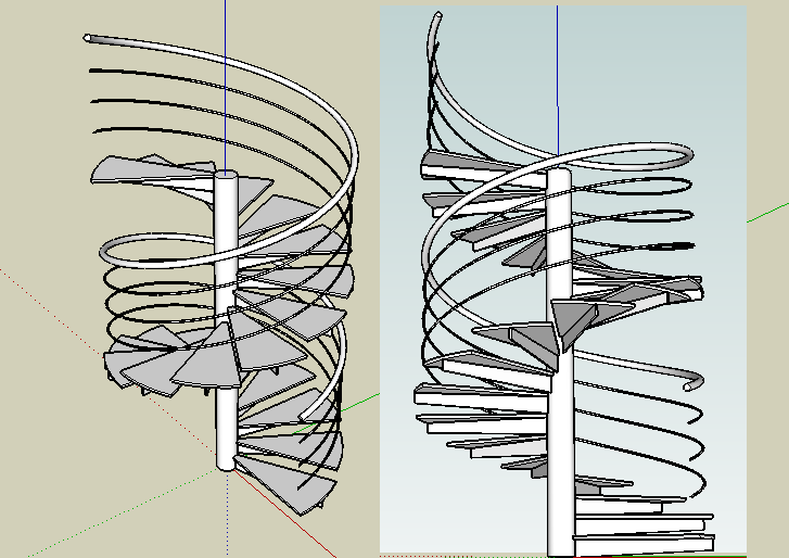
25 Polar array This tool creates array of group/component instance rotated around a center axis. Procedure: Step 1: select a group or component instance, then run the tool. Step 2: enter values in dialog box Step 3: pick to define center axis of rotation. Step 2: enter values then click create array Step 1: select group or component instance before running tool Step 4: pick 2 nd point to define center axis of rotation Step 3: pick start point for center axis of rotation 25


26 Distance along center axis Balusters of spiral staircase created using polar array tool. Create an edge for easy selection of rotation axis 26

27 Path array This tool creates array of group/component instance along a path (a series of connected edges). The groups/component instances are rotated to follow the direction of the path. Procedure: Step 1: select edges of path and group/component instance before running tool. Step 2: select options and key in value into dialog box and click Build array Step 3: pick reference point on group/component instance Step 4: pick start point on path Step 1: select path and group or component instance before running this tool Step 2: select options and enter values, click Build array Step 4: select start point of path Step 3: select reference point on group/ component instance 27
28 Note: you can place the group/component instance at the start point of the path to align it s orientation in relation to the path. In this case, the reference point and the start point can be the same point. Original baluster group Balusters created along path. The balusters are rotated to follow the direction of the path. The chairs are arrayed and aligned around the path with a 3m max distance setting. (chairs and trees are component instances from Google s 3d warehouse.) 28


29 Vertical Walls 1001bit Pro version come with multiple choices for types of walls. To prevent too many icons a wall browser is introduced. Use this browser to select the type of wall to build. Wall 1 standard vertical wall. Option to select a face to define wall sectional profile Wall 2 cavity wall Wall 3 partition wall with studs 29
30 Wall 1 This tool creates vertical walls. The tool will maintain verticality of walls even if it is along a sloping path, and will automatically sort out the profiles necessary when running along a slope. There is also an option to custom define the sectional profile from a face. Procedure: Step 1: run the tool, fill in the desired values in the dialog box and click create wall. Step 2: pick start point of wall Step 3, 4 : continue to pick different points of the wall. Double click on last point or click on the starting point (a construction point is placed to define the start point). Use the arrow keys to keep the target point along a fixed inference; Left arrow green (Y) axis Right arrow red (X) axis Up arrow blue (Z) axis Down arrow inference off To draw walls with exact distance, point the cross hair to define direction, then key in distance. 30
 direction.")
31 Note: Save settings function is only available in Pro version. A construction point is placed at start point. Bring the cross hair back and click on this point to create a closed wall. Double click on last point to build a wall with open end. To build wall with exact distance and fixed direction: Press the left arrow key to lock inference on y (green) direction. You can key in exact distance or point to any reference point when inference is on. The wall tool will maintain vertical sectional profile of wall when in slope. 31

32 The tool automatically sorts out the profile needed at the corners to maintain verticality of wall Setup Profile allows user to pick on a face (flat on x,y plane) to define it as the wall section. This is particularly useful for using this tool to create drains, cornices, walls with coping, etc. Wall profile defined by a face drawn flat on x, y plane using Setup Profile Pick on a face to define profile Next pick to define reference point Pick points to draw wall 32
33 Wall 2 (cavity wall) This tool creates vertical cavity walls. The tool will maintain verticality of walls even if it is along a sloping path, and will automatically sort out the profiles necessary when running along a slope. Procedure: Step 1: run the tool, fill in the desired values in the dialog box and click create wall. Step 2: pick start point of wall Step 3, 4 : continue to pick different points of the wall. Double click on last point or click on the starting point (a construction point is placed to define the start point). Use the arrow keys to keep the target point along a fixed inference; Left arrow green (Y) axis Right arrow red (X) axis Up arrow blue (Z) axis Down arrow inference off To draw walls with exact distance, point the cross hair to define direction, then key in distance. The procedure to create wall is similar to Wall 1. Use the Save settings function to create different preset settings for different scenarios. 33
34 Wall 3 (partition wall with studs) This tool creates vertical partition walls with vertical studs. The tool will maintain verticality of walls even if it is along a sloping path, and will automatically sort out the profiles necessary when running along a slope. Procedure: Step 1: run the tool, fill in the desired values in the dialog box and click create wall. Step 2: pick start point of wall Step 3, 4 : continue to pick different points of the wall. Double click on last point or click on the starting point (a construction point is placed to define the start point). Use the arrow keys to keep the target point along a fixed inference; Left arrow green (Y) axis Right arrow red (X) axis Up arrow blue (Z) axis Down arrow inference off To draw walls with exact distance, point the cross hair to define direction, then key in distance. The procedure to create wall is similar to Wall 1. Use the Save settings function to create different preset settings for different scenarios. 34


35 Opening on wall This tool creates openings on walls (whether grouped or not). There s also an option to create custom shaped openings defined by a face. Procedure Step 1: Run the tool without selecting anything. Step 2: fill in the desired parameters. Note that there s an option to save and select from preset settings. Click Create Opening. Step 3: move the cross hair over the face of the wall. The tool will align the opening on the plane of the wall. Step 4: pick a reference point, then a point identifying the horizontal direction and distance. To place the opening at exact distance, simply point the cross hair to mark the direction and key in exact distance. Step 5: pick a point to define vertical distance or key in vertical distance. Note that you can simple double click to create opening at the cross hair location. Reference point Pick point to define horizontal direction and distance Pick point to define vertical distance 35

36 To create custom shaped opening, click on Setup Profile, then pick a face that is flat on x,y plane to define the profile of the opening. Pick on face on x,y plane to define as profile The outer edges of the face is used as profile of opening. The opening tool can be used to create overlapping openings! 36
37 Horizontal grooves This tool creates horizontal recessed groove lines or protruded lines (use ive value for depth) on selected faces. Procedure Step 1: select the faces and run the tool. Step 2: enter the desired parameters and click create grooves Step 3: pick on a starting level (lower level of groove lines) Starting level 37
38 The horizontal groove tool can be used in conjunction of smooth/soften function to create effect of corrugated sheets on odd shapes. Protruded lines created using horizontal groove tool 38
39 Columns 1001bit Pro version come with multiple choices for types of columns. To prevent too many icons a columns browser is introduced. Use this browser to select the type of columns to build. Column 1 Rectangular column Column 2 Circular and ellipse column Column 3 rectangular column with capital 39
40 Column 4 Tuscan column Column 5 circular Tuscan column Procedure for creating columns Step 1: click on icon to run the column browser, Step 2: select type of column Step 3: enter parameters and click Build Column Step 4: click on insertion point (bottom center of column) Step 5: click to define rotation angle. 40
41 Foundations 1001bit Pro version come with multiple choices for types of foundations. To prevent too many icons a columns browser is introduced. Use this browser to select the type of foundations to build. Foundation 1 standard pad footing Foundation 2 strip footing Note: different types of strip footings can be created by simply modifying the parameters. 41
42 Create Foundation 1 standard pad footing This tool creates pad footings from user defined parameters. Procedure: Step 1: Run this tool and fill in required dimensions, then click Build Foundation Step 2: Pick an insertion point (center top of stump) Step 3: Pick to define rotation (orientation) Note: you can key in exact angle of rotation. Insertion point 42
43 Create Foundation 2 standard strip footing This tool creates strip foundations. The shape of the cross section can be defined. Procedure: Step 1: Run the tool, enter parameters and click Build Foundation Note that you can align the top of the foundation to be on Left, Right or Center to the path. Step 2: Pick points to define path of the strip foundation. Note: you can use direction buttons to fix inference to x, y direction and enter exact distance. Left arrow green (Y) axis Right arrow red (X) axis To draw walls with exact distance, point the cross hair to define direction, then key in distance. Step 3: Double click on last point to create foundation, or click on the construction point marking the first pick point to create a closed loop of strip foundation. 43
44 A construction point is placed on first pick point. In this case the path defined is on the Left of the top of foundation Various type of strip foundations can be created by adjusting the parameters. 44

45 Staircases 1001bit Pro version come with multiple choices for types of staircases. To prevent too many icons a staircases browser is introduced. Use this browser to select the type of staircase to build. Staircase 1 Staircase 2 45
46 Staircase 3 Staircase 4 Staircase 5 46
47 Staircase 6 Staircase 7 Staircase 8 47

48 Staircase 9 Staircase 10 Staircase 11 48
49 Staircase 12 Creating the staircases are quite simple. Step 1: click the icon to run the tools, select type of staircases then click Create Staircase. Step 2: enter parameters into dialog box then click Create Staircase Step 3: pick insertion point Step 4: pick rotation angle. 49
50 The images on the dialog box change in accordance to the text box. 1 st point: insertion point 2 nd point: rotation angle 50
51 Escalator This tool automatically creates standard escalators. The dimensions of standard components are fixed to commonly available escalators. Procedure: Step 1: Click icon to run escalator tool. Step 2: Enter parameters and click Create Escalator Step 3: Pick start point Step 4: Pick to define direction (or pick end point) 51
52 Step 4: 2 nd point: direction of escalator if fixed height, Or actual end point on upper floor if height is to be derived from pick point Step 3: 1 st point: insertion point End height of escalator can either fixed, or derived from 2 nd pick point Angle of escalator is fixed to 30 degrees Number of risers automatically assigned. First and last riser height automaticallu adjusted. Start point: middle bottom of 1 st riser. 52
53 Different parts of escalator are grouped so that materials can be easily assigned. Width/thickness of side panel can be adjusted to create different escalator style. Profiles on plane tool is used to create trusses below escalator. 53
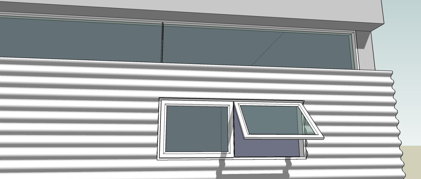
54 Window Frame This tool is used to create window frame and window panels. Procedure: Following is an example of using the window frame tool to create a framed double leaf sliding window. Create a face over the opening on the wall as profile of window. (note that the normal of the face should be same with wall) Select the face before running the window frame tool Note that there are 3 different types for profile. Choose the location of the frame (in relation to the face) 54
55 Window frame is created as a group. The original face is trimmed to the size of remaining opening after the frame. Double click into the group to edit the remaining face. Draw a line/edge to divide the face into 2. Select the face and run the window frame tool again for each face. Note: set one of the frame in front and the other to the back 55
56 Window frame, panels are all created in the same group. Painting: select the whole window and paint all elements Double click into the group to reach the glass face, then paint the glass separately. 56
57 57
58 Door Frame The create door frame tool works similarly to the window frame tool. The only difference is the frame is built without at bottom frame. Please refer window frame tool for procedures. Create a face over the opening on the wall as profile of door. (note that the normal of the face should be same with wall) Select the face before running the door frame tool Door frame created 58
59 Divided Panels The tool divides the selected face into different framed panels. The procedure is similar to that of window frame and door frame. The options on the frame profiles are similar. Select the face before running the panel divider tool Face divided into framed rows and columns Note the beveled edges selected in this example. 59
60 These items created using panel divide tool with different settings 60
61 Perforated Screen This tool creates perforated screens. Thickness, angle, opening dimensions can be freely defined. There is also an option to use custom defined profile as shape of openings. Procedure: Step 1: Select a face and run the tool. Step 2: Enter desired parameters then click Create Opening. Note: that the face can be any shape. 61
62 The perforated screen tool come with a function to make use of user defined profile for openings. To define profile, create a face that is flat on x, y plane. Run the tool and click Setup Profile. Then select the face to define profile and the screen will be created. 62
63 Louvres This tool creates louvers from selected face. There are multiple types of louver profiles to choose from. There is also an option of using user defined profile to create louvers. Procedure: Step 1: pick a face before running the tool. Step 2: Select type of louver, and enter the parameters. Then click Create Louvres. Louvers created from selected face. Note that there are options to place louver in front, middle and behind the face. There is also an option to delete or keep the selected face after generating louvers. And of course, the face can be of any shape. 63
64 Louvre 0 - without thickness Louvre 1 Louvre 2 Louvre 3 64
65 Louvre 4 Louvre 5 Louvre 6 65
66 The louvre tool can handle face of any profile as well as holes. Adjust the louvre angle 2 parameter to create louvers to any angle. The louver tool come with a function to make use of user defined profile as louver. To define profile, create a face that is flat on x, y plane. Run the tool and click Setup Profile. Then select the face to define profile and the louvers will be created. 66
67 Profiles On Plane The tool converts edges on to profiled sections. There are multiple options of profile to choose from. Type 0 - Rectangular Section Type 1 - Circular Section Type 2 Rectangular with rounded corners Type 3 I section 67
68 Type 4 H section Procedure: Step 1: Select edges then run Profile on Plane tool. (Works on open edges. Non coplanar edges will be projected to common plane.) Step 2: Enter width and height, then click Create Profiles Profile on plane tool can be used to create walls from plans 68
69 Face drawn flat on x, y plane to define profile Users can also create custom defined profiles. Create a face flat on x, y plane to define profile. Click Setup Profile to make use of custom defined profile. Profile created using custom defined section. 69
70 Joists Create joists tool automatically creates joists, rafters, battens, etc on selected face. There are multiple type of profiles as well as multiple options in ways to layout the joists. Joist 0 Rectangular section Joist 1 I section Joist 2 C cold formed section 70
71 Joist 3 - ] hot rolled section Joist 4 L hot rolled section Joist 5 T section Joist 6 rectangular steel section 71
72 Procedure: Step 1: select a face and run the tool. Step 2: select the desired sectional profile, dimensions, spacing, and click Create Joists Note that in this example, the normal of the face is downwards. This is because we want to create the joists below the face. Pick 2 nd point to define joist direction Pick 1 st point of joist direction 72


73 Use reverse face to change the normal to upwards for the next level of joists. Joists arranged below selected face because face is facing down. Next we create cold form C channel joists above the steel sections. Pick points to define the directions of joists 2 nd layer of joists created. We ll manually delete the original face or use it as floor. 73
74 Joist tool can handle face of any shape including holes and aligned to any angle. The joists tool comes with an option to make use of user defined shapes as profile of joists. Step 1: Just draw a face that is flat on x, y plane, Step 2: select the face to place the joists on and the call the tool, Step 3: click on Setup Profile Step 4: click on the face to use as profile. Step 5: pick points to define direction of joists. Some of the edges may need manual patching up. Create a face flat on x,y plane to define as profile of joists The tool will attempt to close up open ends as much as possible. Depends on complexity, there might be open ends that need manual touch ups. 74
75 Roof Rafters, Battens/Purlins This tool automatically creates roof rafters, purlins/battens, fascia board from selected faces. There a multiple choices of rafters and battens to choose from. Procedure: Step 1: Select faces that make up the roof. Step 2: call the tool, enter parameters and select options, then click Create Rafters, Battens/Purlins The tool automatically creates and spaced out rafters, battens and fascia boards. Note that the original faces remains and are selected in case you need to use it for roof surfaces. Press delete to remove. 75
76 The different types of rafters are as follows Rafter 0 Rafter 1 Rafter 2 Rafter 3 76
77 There are different types of battens/purlins to choose from Batten 0 Batten 1 Battens 2 Battens 3 77
78 78
79 Hip Roof This tool automatically solves hip roof geometry from face of any shape. Procedure: Step 1: select the face before running this tool. Step 2: call the tool and enter parameters, then click Create Hip Roof Note that this tool works with faces with holes. 79
80 Set the vertical offset distance, overhang and fascia height to create an outline of hip roof above wall plate level. Original face 80
81 Metal Deck This tool converts a face into metal decks with different profiles. Procedure: Step 1: select a face, then run tool Step 2: select type of profile and enter parameters, click Create Metal Deck Step 3: pick points to define direction of ribs. 1 st pick point 2 nd pick point to define direction of ribs. 81
82 There are currently 3 types of profiles Metal deck 0 Metal deck 1 Metal deck 2 The metal deck tool works on faces of any shape, orientations and faces with holes. The original face is left remaining. Manually delete if desired. 82

83 83
84 Cut and Fill Site This tool is meant for placing a flat plane on a contoured site. The tool will automatically cut and fill areas and the angle of the retaining walls can be defined. Procedure: Step 1: select the site (may have to be exploded), then run the tool Step 2: pick on the face defining the shape of the platform. (Have to be placed above the contoured site). Step 3: pick a level on the contour, or type in actual level. 84
85 85
86 Site Boundary This tool traces the boundary of a face onto a contour. Procedure: Step 1: select the contour face Step 2: pick the face defining the boundaries (have to be placed above the contour) The boundary of the upper face is traced onto the contour. 86
87 Trace Contour Lines This tool traces contour lines at fixed vertical distance intervals. (note: it applies to all objects in active model) Procedure: Step 1: Run the tool (no need to select anything) Step 2: Pick a starting level. The dialog box will display the actual level picked. You can key in exact level if desired. Step 3: Enter desired vertical distance interval, click OK. 87
Roof Tutorial. Chapter 3:
 Chapter 3: Roof Tutorial The majority of Roof Tutorial describes some common roof styles that can be created using settings in the Wall Specification dialog and can be completed independent of the other
Introduction to Autodesk Inventor for F1 in Schools
 Introduction to Autodesk Inventor for F1 in Schools F1 in Schools Race Car In this course you will be introduced to Autodesk Inventor, which is the centerpiece of Autodesk s digital prototyping strategy
TABLE OF CONTENTS. INTRODUCTION... 5 Advance Concrete... 5 Where to find information?... 6 INSTALLATION... 7 STARTING ADVANCE CONCRETE...
 Starting Guide TABLE OF CONTENTS INTRODUCTION... 5 Advance Concrete... 5 Where to find information?... 6 INSTALLATION... 7 STARTING ADVANCE CONCRETE... 7 ADVANCE CONCRETE USER INTERFACE... 7 Other important
3D Drawing. Single Point Perspective with Diminishing Spaces
 3D Drawing Single Point Perspective with Diminishing Spaces The following document helps describe the basic process for generating a 3D representation of a simple 2D plan. For this exercise we will be
Introduction to Autodesk Inventor for F1 in Schools
 F1 in Schools race car Introduction to Autodesk Inventor for F1 in Schools In this course you will be introduced to Autodesk Inventor, which is the centerpiece of Autodesk s Digital Prototyping strategy
Introduction to CATIA V5
 Introduction to CATIA V5 Release 16 (A Hands-On Tutorial Approach) Kirstie Plantenberg University of Detroit Mercy SDC PUBLICATIONS Schroff Development Corporation www.schroff.com www.schroff-europe.com
SpaceClaim Introduction Training Session. A SpaceClaim Support Document
 SpaceClaim Introduction Training Session A SpaceClaim Support Document In this class we will walk through the basic tools used to create and modify models in SpaceClaim. Introduction We will focus on:
Kitchen and Bath Design Tutorial
 Chapter 5: Kitchen and Bath Design Tutorial This tutorial continues where the Materials Tutorial left off. You should save this tutorial using a new name to archive your previous work. The tools and techniques
Raising the Roof Creating Roofs in Revit David Cohn
 David Cohn AB322-1 Roofs are one of the most complex architectural elements to model, but with Revit you can create just about any type of roof. This class will explore the best methods for creating various
Basic AutoSketch Manual
 Basic AutoSketch Manual Instruction for students Skf-Manual.doc of 3 Contents BASIC AUTOSKETCH MANUAL... INSTRUCTION FOR STUDENTS... BASIC AUTOSKETCH INSTRUCTION... 3 SCREEN LAYOUT... 3 MENU BAR... 3 FILE
Microsoft Excel 2010 Charts and Graphs
 Microsoft Excel 2010 Charts and Graphs Email: training@health.ufl.edu Web Page: http://training.health.ufl.edu Microsoft Excel 2010: Charts and Graphs 2.0 hours Topics include data groupings; creating
 Edinburgh COLLEGE of ART ARCHITECTURE 3D Modelling in AutoCAD - tutorial exercise The screen The graphics area This is the part of the screen in which the drawing will be created. The command prompt area
Understand the Sketcher workbench of CATIA V5.
 Chapter 1 Drawing Sketches in Learning Objectives the Sketcher Workbench-I After completing this chapter you will be able to: Understand the Sketcher workbench of CATIA V5. Start a new file in the Part
House Design Tutorial
 Chapter 2: House Design Tutorial This House Design Tutorial shows you how to get started on a design project. The tutorials that follow continue with the same plan. When we are finished, we will have created
CATIA Drafting TABLE OF CONTENTS
 TABLE OF CONTENTS Introduction...1 Drafting...2 Drawing Screen...3 Pull-down Menus...4 File...4 Edit...5 View...6 Insert...7 Tools...8 Drafting Workbench...9 Views and Sheets...9 Dimensions and Annotations...10
3D Drawing. Single Point Perspective with Diminishing Spaces
 3D Drawing Single Point Perspective with Diminishing Spaces The following document helps describe the basic process for generating a 3D representation of a simple 2D plan. For this exercise we will be
2013 Getting Started Guide
 2013 Getting Started Guide The contents of this guide and accompanying exercises were originally created by Nemetschek Vectorworks, Inc. Vectorworks Fundamentals Getting Started Guide Created using: Vectorworks
IES <Virtual Environment> Tutorial. ModelIT (Version 6.0)
") IES Tutorial ModelIT (Version 6.0) 1 Introduction: ModelIT Tutorial This document shows you how to use ModelIT, IES s 3D building geometry modelling tool. The tutorial is intended
IES Tutorial ModelIT (Version 6.0) 1 Introduction: ModelIT Tutorial This document shows you how to use ModelIT, IES s 3D building geometry modelling tool. The tutorial is intended
Kitchen and Bath Design Tutorial
 Adding Cabinets Chapter 5: Kitchen and Bath Design Tutorial This tutorial continues where the Materials Tutorial left off. You should save this tutorial using a new name to archive your previous work.
SketchUp Instructions
 SketchUp Instructions Every architect needs to know how to use SketchUp! SketchUp is free from Google just Google it and download to your computer. You can do just about anything with it, but it is especially
SolidWorks. SolidWorks Teacher Guide. and Student Courseware
 SolidWorks SolidWorks Teacher Guide and Student Courseware SolidWorks Corporation Outside the U.S.: +1-978-371-5011 300 Baker Avenue Fax: +1-978-371-7303 Concord, Massachusetts 01742 USA Email: info@solidworks.com
Kitchen and Bath Design Tutorial
 Adding Cabinets Kitchen and Bath Design Tutorial This tutorial continues where the Interior Design Tutorial left off. You should save this tutorial using a new name to archive your previous work. The tools
An introduction to 3D draughting & solid modelling using AutoCAD
 An introduction to 3D draughting & solid modelling using AutoCAD Faculty of Technology University of Plymouth Drake Circus Plymouth PL4 8AA These notes are to be used in conjunction with the AutoCAD software
Roof Tutorial. Chapter 3:
 Chapter 3: Roof Tutorial The first portion of this tutorial can be completed independent of the previous tutorials. We ll go over some common roof styles that can be created using settings in the Wall
Getting Started With DraftSight A Guide For AEC Users
 Getting Started With DraftSight A Guide For AEC Users DraftSight.com Facebook.com/DraftSight Welcome to DraftSight a valuable tool for any AEC professional! DraftSight is more than a free, professional-grade
CATIA Wireframe & Surfaces TABLE OF CONTENTS
 TABLE OF CONTENTS Introduction... 1 Wireframe & Surfaces... 2 Pull Down Menus... 3 Edit... 3 Insert... 4 Tools... 6 Generative Shape Design Workbench... 7 Bottom Toolbar... 9 Tools... 9 Analysis... 10
Part Design. Preface What's New? Getting Started Basic Tasks Advanced Tasks Workbench Description Customizing Glossary Index
 Part Design Preface What's New? Getting Started Basic Tasks Advanced Tasks Workbench Description Customizing Glossary Index Dassault Systèmes 1994-99. All rights reserved. Preface The CATIA Version 5 Part
Autodesk Fusion 360 Badge Guide: Design an F1 in Schools Trophy
 Autodesk Fusion 360 Badge Guide: Design an F1 in Schools Trophy Abstract: Gain basic understanding of creating 3D models in Fusion 360 by designing an F1 in Schools trophy. This badge may be claimed by
Creating a 2D Geometry Model
 Creating a 2D Geometry Model This section describes how to build a 2D cross section of a heat sink and introduces 2D geometry operations in COMSOL. At this time, you do not model the physics that describe
Chapter 9. Editing Features. Learning Objectives
 Chapter 9 Editing Features Learning Objectives After completing this chapter, you will be able to: Edit features. Edit sketches of the sketch based features. Edit the sketch plane of the sketch based features.
Chapter 1. Creating Sketches in. the Sketch Mode-I. Evaluation chapter. Logon to www.cadcim.com for more details. Learning Objectives
 Chapter 1 Creating Sketches in Learning Objectives the Sketch Mode-I After completing this chapter you will be able to: Use various tools to create a geometry. Dimension a sketch. Apply constraints to
What s New V 11. Preferences: Parameters: Layout/ Modifications: Reverse mouse scroll wheel zoom direction
 What s New V 11 Preferences: Reverse mouse scroll wheel zoom direction Assign mouse scroll wheel Middle Button as Fine tune Pricing Method (Manufacturing/Design) Display- Display Long Name Parameters:
SolidWorks: Mirror, Revolve, and. Introduction to Robotics
 SolidWorks: Mirror, Revolve, and Circular Pattern Introduction to Robotics Let s Review At this point we have learned the following: Extrude Boss/Base Extruded Cut Adding Relations and Dimensions Linear
Chapter 3 Installing Over-the-Post Railing on an L-Shaped Stair
 49 Chapter 3 Installing Over-the-Post Railing on an L-Shaped Stair In this chapter: The Over-the-Post Balustrade System Determining the Rail Centerline Using Rail Bolts Making a Pitch Block Laying Out
Autodesk Fusion 360: Assemblies. Overview
 Overview In this module you will learn how different components can be put together to create an assembly. We will use several tools in Fusion 360 to make sure that these assemblies are constrained appropriately
Layout Tutorial. Getting Started
 Getting Started Layout Tutorial This tutorial will explain how create a layout template, send views to a layout page, then save the document in PDF format. In this tutorial you will learn about: Creating
Pro/ENGINEER Wildfire 4.0 Basic Design
 Introduction Datum features are non-solid features used during the construction of other features. The most common datum features include planes, axes, coordinate systems, and curves. Datum features do
Excel -- Creating Charts
 Excel -- Creating Charts The saying goes, A picture is worth a thousand words, and so true. Professional looking charts give visual enhancement to your statistics, fiscal reports or presentation. Excel
Speed-Mat Rectangle Cutter
 Speed-Mat Rectangle Cutter 1 Honeycomb baseboard. 2 Left hold down. 14 3 Bottom hold down. 4 4 Left / right rule. 8 5 8 5 Left / right rule pointer. 1 6 Top / bottom rule. 7 Top / bottom rule pointer.
Using Microsoft Word. Working With Objects
 Using Microsoft Word Many Word documents will require elements that were created in programs other than Word, such as the picture to the right. Nontext elements in a document are referred to as Objects
SolidWorks Tutorial 4 CANDLESTICK
 SolidWorks Tutorial 4 CANDLESTICK Candlestick In this tutorial you will make a simple container and a candlestick out of sheetmetal. You will learn about working with sheet metal in SolidWorks. We will
Sheet Metal Design: Beyond Bends and Flanges
 11/30/2005-8:00 am - 9:30 am Room:Pelican 1 (Swan) Walt Disney World Swan and Dolphin Resort Orlando, Florida Sheet Metal Design: Beyond Bends and Flanges Anthony B. Rodriguez - KETIV Technologies MA31-2
Modeling Curved Surfaces
 Modeling Cylindrical and Curved Theory Views of Cylinders Contour Lines Extruded Surfaces Revolved Surfaces & Cutouts Profile Shape Axis of Revolution Swept Surfaces & Cutouts Profile Shape Path Curves
House Design Tutorial
 Chapter 2: House Design Tutorial This House Design Tutorial shows you how to get started on a design project. The tutorials that follow continue with the same plan. When you are finished, you will have
Sheet Metal Design. Preface What's New? Getting Started Basic Tasks Workbench Description Customizing Glossary Index
 Sheet Metal Design Preface What's New? Getting Started Basic Tasks Workbench Description Customizing Glossary Index Dassault Systèmes 1994-99. All rights reserved. Preface The V5 CATIA - Sheet Metal Design
LESSON 7: IMPORTING AND VECTORIZING A BITMAP IMAGE
 LESSON 7: IMPORTING AND VECTORIZING A BITMAP IMAGE In this lesson we ll learn how to import a bitmap logo, transform it into a vector and perform some editing on the vector to clean it up. The concepts
Pro/ENGINEER Wildfire 5.0 Introduction to Surface Modeling
 Introduction Several advanced surface types are available as listed below. Variable Section Sweep Boundary Blend Section to Surfaces Blend Surface to Surface Blend A surface is created by sweeping a single
Adobe Illustrator CS5 Part 1: Introduction to Illustrator
 CALIFORNIA STATE UNIVERSITY, LOS ANGELES INFORMATION TECHNOLOGY SERVICES Adobe Illustrator CS5 Part 1: Introduction to Illustrator Summer 2011, Version 1.0 Table of Contents Introduction...2 Downloading
Communicate: In Print
 Communicate: In Print A simple guide Work areas Communicate: In Print has two different modes in which to edit your documents: Create and Adjust modes. These are easily interchangeable and the toolbars
Creating an invitation
 Creating an invitation Michaela Maginot About the author Michaela Maginot lives in Unterhaching, Germany, not too far from Munich. She graduated from the Deutschen Meisterschule für Mode (German Master
Google SketchUp Design Exercise 3
 Google SketchUp Design Exercise 3 This advanced design project uses many of SketchUp s drawing tools, and involves paying some attention to the exact sizes of what you re drawing. You ll also make good
Introduction to the TI-Nspire CX
 Introduction to the TI-Nspire CX Activity Overview: In this activity, you will become familiar with the layout of the TI-Nspire CX. Step 1: Locate the Touchpad. The Touchpad is used to navigate the cursor
Drawing a Bedroom Floorplan
 Appendix A Drawing a Bedroom Floorplan In this chapter, you will learn the following to World Class standards: Draw a Bedroom Floorplan Draw the Bedroom Walls Draw and Dimension the Bedroom Door Draw and
Getting Started Guide
 3D Architect Home Designer Getting Started Guide Produced and published in the UK by Eleco Software Limited 2014 Eleco plc. All rights reserved. The software and hardware names and labels used in this
TurboCAD Architectural
 TurboCAD Architectural Version 15 Getting Started Guide IMSI/Design LLC, US 100 Rowland Blvd. Novato. CA 94945, USA Tel: +1-415-878-4000 Fax: +1-415-897-2544 Web Site www.imsisoft.com www.turbocad.com
Mastercam X6 Basic 3D Design
 Basic 3D Design mastercam x getting started tutorials Mastercam X6 Basic 3D Design December 2011 Be sure you have the latest information! Information might have been changed or added since this document
Create a Poster Using Publisher
 Contents 1. Introduction 1. Starting Publisher 2. Create a Poster Template 5. Aligning your images and text 7. Apply a background 12. Add text to your poster 14. Add pictures to your poster 17. Add graphs
Publisher 2010 Cheat Sheet
 April 20, 2012 Publisher 2010 Cheat Sheet Toolbar customize click on arrow and then check the ones you want a shortcut for File Tab (has new, open save, print, and shows recent documents, and has choices
Datum > Curve KIM,ME,NIU
 Datum > Curve Intersect First create at least one quilt on the surface of the model. Feature > Surface (> New) > Copy (do not use offset that creates a surface off the solid surface even with zero offset)
ME 111: Engineering Drawing
 ME 111: Engineering Drawing Lecture # 14 (10/10/2011) Development of Surfaces http://www.iitg.ernet.in/arindam.dey/me111.htm http://www.iitg.ernet.in/rkbc/me111.htm http://shilloi.iitg.ernet.in/~psr/ Indian
Importing and Opening an Alignment
 Chapter 6 Alignment Files An alignment defines the route of a road, utility line, water way, etc., and is typically comprised of both horizontal and vertical elements. Also, an alignment may include cross-sectional
If you know exactly how you want your business forms to look and don t mind
 appendix e Advanced Form Customization If you know exactly how you want your business forms to look and don t mind detail work, you can configure QuickBooks forms however you want. With QuickBooks Layout
Sketcher. Preface What's New? Getting Started Basic Tasks Customizing Workbench Description Glossary Index
 Sketcher Preface What's New? Getting Started Basic Tasks Customizing Workbench Description Glossary Index Dassault Systèmes 1994-99. All rights reserved. Preface CATIA Version 5 Sketcher application makes
Creating 2D Isometric Drawings
 1-(800) 877-2745 www.ashlar-vellum.com Creating 2D Isometric Drawings Using Graphite TM Copyright 2008 Ashlar Incorporated. All rights reserved. C62DISO0806. Ashlar-Vellum Graphite No matter how many Top,
Layout Tutorial. Chapter 10: Getting Started
 Chapter 10: Layout Tutorial In this tutorial we will create a layout template, send a few views to a layout page, then save this document in PDF format. In this tutorial you will learn about: Creating
Designing and Drawing a Sprocket Visualizing ideas through the creation of CAD solid models is a key engineering skill.
 05 Webster St. Hanover Massachusetts 0339 Tel. 78 878 5 Fax 78 878 6708 Designing and Drawing a Sprocket Visualizing ideas through the creation of CAD solid models is a key engineering skill. The following
Creating Drawings in Pro/ENGINEER
 6 Creating Drawings in Pro/ENGINEER This chapter shows you how to bring the cell phone models and the assembly you ve created into the Pro/ENGINEER Drawing mode to create a drawing. A mechanical drawing
Castle Modeling. In this PDF tutorial we will be modeling a simple castle as pictured above.
 Course: 3D Design Title: Castle Modeling Blender: Version 2.6X Level: Beginning Author; Neal Hirsig (nhirsig@tufts.edu) May, 2012 This tutorial assumes that you already know how to: Display orthographic
Table of contents. What is new in Advance Steel 2011
 Table of contents WELCOME TO ADVANCE STEEL 2011, PART OF THE GRAITEC BIM SOLUTION... 5 NEW COMMON INSTALLATION PROCESS... 6 GRAITEC ADVANCE MANAGER... 7 Easy to use GUI to customize settings...7 Settings...8
CREATING A 3D VISUALISATION OF YOUR PLANS IN PLANSXPRESS AND CORTONA VRML CLIENT
 CREATING A 3D VISUALISATION OF YOUR PLANS IN PLANSXPRESS AND CORTONA VRML CLIENT 20-25 Minutes This topic is for users of PlansXpress Total Toolkit Edition. To upgrade to PlansXpress Total Toolkit, call
Best Barns USA Assembly Book
 Best Barns USA Assembly Book Revised November 27, 2013 the Easton - R 12'x 20' Manufactured by Reynolds Building Systems, Inc. 205 Arlington Drive Greenville, PA 16125 724-646-3775 This manual is copyrighted.
AMERICAN GOTHIC PLAYHOUSE
 AMERICAN GOTHIC PLAYHOUSE Project Plan #856 Sheet 1 of 5 Pick a spot and get started with the beautiful that your kids will love. The design of the playhouse includes 35 square feet of interior space plus
SolidWorks Tutorial 3 MAGNETIC BLOCK
 SolidWorks Tutorial 3 MAGNETIC BLOCK Magnetic Block In this exercise you will make a magnetic block. To do so, you will create a few parts, which you will assemble. You will learn the following new applications
Gate Leg Drop Leaf Table Plans
 Preparing the table top blanks: Cut and glue enough 3/4 stock to make three panels 40 long by 24 wide (they will be cut to final size at a later time). While the glue dries we will work on the legs. Preparing
MET 306. Activity 8a. Mechanism Design Creo 2.0 Level 7 POINT A GROUND LINK LINK 1 LINK 2 LINK 3 POINT B 10/15/2010 1
 Mechanism Design Creo 2.0 Level 7 POINT A LINK 1 GROUND LINK LINK 2 LINK 3 POINT B 10/15/2010 1 Download parts ground, key, link_1, link_2, link_3 and pulley from the V:/MET_306/Activity_8_Creo drive.
AutoCAD Architecture 2012 UK Content Tools
 AutoCAD Architecture 2012 UK Content Tools Contents Contents... 1 Installation... 2 Loading the utilities... 2 Utilities Overview... 3 Menu and Toolbar... 3 Content Generation... 3 Content Publishing...
A simple three dimensional Column bar chart can be produced from the following example spreadsheet. Note that cell A1 is left blank.
 Department of Library Services Creating Charts in Excel 2007 www.library.dmu.ac.uk Using the Microsoft Excel 2007 chart creation system you can quickly produce professional looking charts. This help sheet
4 Manipulating Elements
 4 Manipulating Elements In the context of this course, Manipulation of elements means moving, copying, rotating, scaling and some other similar operations. We will find that manipulations are always a
SolidWorks Implementation Guides. Sketching Concepts
 SolidWorks Implementation Guides Sketching Concepts Sketching in SolidWorks is the basis for creating features. Features are the basis for creating parts, which can be put together into assemblies. Sketch
Generative Drafting. Page 1 1997 2001 DASSAULT SYSTEMES. IBM Product Lifecycle Management Solutions / Dassault Systemes
 Generative Drafting Page 1 Tutorial Objectives Description This Tutorial is an introduction to Generative Drafting. Message To show how CATIA V5 allows the user to automatically generate associative drafting
Creating an invitation
 Creating an invitation Michaela Maginot Concept and design Invitation complete with gift box, card, and transparent envelope. For more options, please visit www.corel.com/design collection. The goal was
How to build text and objects in the Titler
 How to build text and objects in the Titler You can use the Titler in Adobe Premiere Pro to create text and geometric objects. There are three methods for creating text, each capable of producing either
CATIA Electrical Harness Design TABLE OF CONTENTS
 TABLE OF CONTENTS Introduction...1 Electrical Harness Design...2 Electrical Harness Assembly Workbench...4 Bottom Toolbar...5 Measure...5 Electrical Harness Design...7 Defining Geometric Bundles...7 Installing
Sweet Home 3D version 3.0 and later. Tutorial for sloping roofs and ceilings, dormers and more.
 Sweet Home 3D version 3.0 and later Tutorial for sloping roofs and ceilings, dormers and more. Hans Dirkse - january 2011 Table of Contents 1 - Introduction 2 - Sloping ceiling 3 - Sloping ceiling with
Window Glass Design 5 According to ASTM E 1300
 A User s Guide to: Window Glass Design 5 According to ASTM E 1300 A product of: 1 Table of Contents Table of Contents List of Figures Chapter 1: Window Glass Design 5 1.1 Introduction 1.2 Features ii iv
Scientific Graphing in Excel 2010
 Scientific Graphing in Excel 2010 When you start Excel, you will see the screen below. Various parts of the display are labelled in red, with arrows, to define the terms used in the remainder of this overview.
12-1 Representations of Three-Dimensional Figures
 Connect the dots on the isometric dot paper to represent the edges of the solid. Shade the tops of 12-1 Representations of Three-Dimensional Figures Use isometric dot paper to sketch each prism. 1. triangular
Layout Tutorial. Chapter 10: Getting Started
 Chapter 10: Layout Tutorial In this tutorial we will create a layout template, send a few views to a layout page, then save this document in PDF format. In this tutorial you will learn about: Creating
511 - Creating Structural Frame Designs
 4 th Generation VLC courtesy of Edison2 511 - Creating Structural Frame Designs Rahul Kulkarni, Manager, Product Design, Pune Center, Siemens PLM Software #SEU13 Agenda: 511 - Creating Structural Frame
Geometer s Sketchpad. Discovering the incenter of a triangle
 Geometer s Sketchpad Discovering the incenter of a triangle Name: Date: 1.) Open Geometer s Sketchpad (GSP 4.02) by double clicking the icon in the Start menu. The icon looks like this: 2.) Once the program
10. THERM DRAWING TIPS
 10. THERM DRAWING TIPS 10.1. Drawing Tips The THERM User's Manual describes in detail how to draw cross-sections in THERM. This section of the NFRC Simualation Training Manual presents some additional
9.8.1.1. General (1) This Section applies to the design and construction of interior and exterior stairs, steps, ramps, railings and guards.
 This Section applies to the design and construction of interior and exterior stairs, steps, ramps, railings and guards.") Section 9.8. Stairs, Ramps, Handrails and Guards 9.8.1. Application 9.8.1.1. General (1) This Section applies to the design and construction of interior and exterior stairs, steps, ramps, railings and
Section 9.8. Stairs, Ramps, Handrails and Guards 9.8.1. Application 9.8.1.1. General (1) This Section applies to the design and construction of interior and exterior stairs, steps, ramps, railings and
Working With Animation: Introduction to Flash
 Working With Animation: Introduction to Flash With Adobe Flash, you can create artwork and animations that add motion and visual interest to your Web pages. Flash movies can be interactive users can click
3D Viewer. user's manual 10017352_2
 EN 3D Viewer user's manual 10017352_2 TABLE OF CONTENTS 1 SYSTEM REQUIREMENTS...1 2 STARTING PLANMECA 3D VIEWER...2 3 PLANMECA 3D VIEWER INTRODUCTION...3 3.1 Menu Toolbar... 4 4 EXPLORER...6 4.1 3D Volume
PowerPoint: Graphics and SmartArt
 PowerPoint: Graphics and SmartArt Contents Inserting Objects... 2 Picture from File... 2 Clip Art... 2 Shapes... 3 SmartArt... 3 WordArt... 3 Formatting Objects... 4 Move a picture, shape, text box, or
Cedar Cottage Doghouse Plans
 Overlapping cedar shingles add an element of charm to this medium size doghouse. The walls, floor, and trim are constructed of solid cedar, making it naturally weather resistant and provides excellent
7 Enclosed Areas. When you have completed this chapter, you will be able to:
 7 Enclosed Areas Our designs so far have consisted entirely of open linework, except for a brief introduction to Fill Attributes on page 3-15. Closed linework may delineate an Area, such as a section of
Lesson #13 Congruence, Symmetry and Transformations: Translations, Reflections, and Rotations
 Math Buddies -Grade 4 13-1 Lesson #13 Congruence, Symmetry and Transformations: Translations, Reflections, and Rotations Goal: Identify congruent and noncongruent figures Recognize the congruence of plane
HowTo Rhino & ICEM. 1) New file setup: choose Millimeter (automatically converts to Meters if imported to ICEM)
 New file setup: choose Millimeter (automatically converts to Meters if imported to ICEM)") HowTo Rhino & ICEM Simple 2D model 1) New file setup: choose Millimeter (automatically converts to Meters if imported to ICEM) 2) Set units: File Properties Units: Model units: should already be Millimeters
HowTo Rhino & ICEM Simple 2D model 1) New file setup: choose Millimeter (automatically converts to Meters if imported to ICEM) 2) Set units: File Properties Units: Model units: should already be Millimeters