Low Power Low Tower SFN networks Interference Analysis
|
|
|
- Neil Melton
- 9 years ago
- Views:
Transcription
1 Low Power Low Tower SFN networks Interference Analysis 1/44
2 TABLE OF CONTENT Part A - Overview... 3 A.1 - Background... 3 A.2 - Objectives... 4 A.3 - Planning assumptions... 5 A Simulation parameters... 5 A Time model for signal contribution / interference... 6 A Propagation model used for the simulations... 7 Part B - Overall coverage simulations... 7 B.1 - Geographic area and base stations... 7 B.2 - Network configurations analyzed B.3 - Configuration B.4 - Configuration B Simulation results B Analysis of interfered areas in SFN 4 ploygon B.5 - Configuration B.6 - Configuration B.7 - Configuration Part C - Local optimization in difficult areas...35 C.1 - Configuration C.2 - Configuration Part D - Overall analysis of the solution studied /44
3 Part A - Overview This portion will provide an overview of the deployment topology proposed, as well as the coverage objectives within dense areas or rural areas. The overview will also set the performance targets and underlying assumptions on the technology deployed. A.1 - Background The MHz has been historically used in Europe for terrestrial broadcast network, delivering public and private broadcast through fixed rooftop reception. Advances in technology and evolution of consumer habits have triggered discussions about the future use of the MHz. In particular, there is a trend towards mobile consumption for audiovisual content (including audiovisual media services) creating the necessity to consider how broadcasting and mobile services could complement each other in the delivery of audiovisual (both linear and non-linear) content to mobile terminals. The topic was discussed in the High Level Group on the future use of the UHF band led by Pascal Lamy and the Plum Consulting/Farncombe study on broadcast-broadband convergence, both initiatives from the European Commission. From the CEPT side, the ECC Report 224 on Long Term Vision for the UHF broadcasting band described, in particular, a number of scenarios corresponding to convergence of broadcast services on the mobile platform. All reports and study groups acknowledged the potential of a converged platform, designed as a Low Power Low Tower network operating in Supplemental DL mode as a nationwide Single Frequency Network (SFN). While technical feasibility of such an approach was recognized, reports stressed that further studies were required in order to address precisely the coverage achieved by such networks at the border between two SFNs. The study below aims at providing a full assessment of the coverage properties of downlink LPLT networks for the delivery of broadcast content, especially at the border of two SFNs. The technical proposal is to reuse existing base stations operated by mobile operators to deliver an LTE Broadcast service in the MHz band. Reusing existing sites provides numerous benefits, in particular in order to reduce the cost of deployment of such a network. The service should deliver 2 bps/hz to mobile devices and fixed rooftop antennas alike, in order to significantly increase the capacity of the mobile platform. The LTE Broadcast service considered corresponds to an evolution of the current LTE embms standard, in particular in order to support longer cyclic prefixes (200 µsec). One of the benefits of adopting LTE as a standard for broadcasting is to leverage the advanced signal processing capabilities of LTE terminals. LTE embms only requires 16dB of SINR to deliver 2bps/Hz in a very challenging mobile environment. Fixed rooftop reception is ensured with much lower SINR requirements. LTE receivers also support features - such as interference cancellation - which improve performance in challenging SNIR environment. Mobile networks deliver high geographical coverage over either 900 and/or 800 MHz networks. Reusing such sites to deliver LTE broadcast at 2bps/Hz is quite straightforward in terms of pure coverage properties. Challenges arise at the border of two such Single Frequency Networks, for example at the border between two countries. In such area, the signal strength of the desired signal is similar, or even sometimes slightly lower, than the signal from the neighboring (and in this case interfering) network. Fixed rooftop antenna typically offer 16dB of back-to-front ratio, meaning that in the case where both signal deliver similar signal strength, adequate pointing of the fixed rooftop antenna ensures that the desired signal is received with around 16dB signal to interference ratio. 3/44
4 Given that the SINR required for fixed rooftop reception is significantly lower than 16dB and that LTE receiver implement interference cancellation algorithm, the theoretical analysis indicates that fixed rooftop reception should be possible, even at the border between two SFNs. A.2 - Objectives Early studies submitted to ECC TG6 by several DVB-T research groups questioned the feasibility of fixed rooftop reception at the border between two SFNs. In particular, the BBC proposed a study based on some small regional SFNs in England and the selection of base stations from the 900 MHz network of one UK MNO. The study assumed specific transmission site characteristics and that the LTE receiver would behave in a similar manner than a DVB-T receiver, in particular with regards to signals received outside of cyclic prefix length and interfering signal from adjacent SFNs. Under such assumption, the coverage was demonstrated to be quite consistent inside one SFN, but challenging at SFNs borders. In the following sections, the BBC study is extended in order to: -Reuse the BBC site selection, -adopt realistic LTE receiver characteristics, -determine the coverage of such a network under various receiving modes, -determine whether the coverage of such an SFN can be optimized to match the border of administrative broadcasting regions. The study objectives are then the following: - Select existing sites from UK mobile operators and build different networks (up to 7), each SFN having its own coverage area. - Provide SINR maps on the geographical area that will: - Take into account an extended cyclic prefix of 200µs. - Take into account different receiving antenna configurations (standard fixed rooftop antenna, advanced fixed rooftop antenna with excellent front to back ratio, mobile terminal antenna). - Take into account SFN self-interference, and interference from neighboring SFNs. - Perform a network optimization where required (Power, downtilt, antenna base stations, orientation of the receiving antennas, identification of solutions in areas with strong difficulties). The presentation of results would be, based on maps of the BBC, to show how the non-reception zones will be modified with: - Optimization of the transmission network. - Use of receiving antennas with better performance in areas with strong interference. - In extreme cases, use of two receiving antennas for joint reception at the boundary of two SFNs. - Conversely, identify intra SFN areas where the mobile reception would be possible. 4/44
5 A.3 - Planning assumptions A Simulation parameters The following receiving thresholds have been used for the three different antenna configurations. Fixed Fixed advanced Mobile Receiver Noise (dbm) Min SNIR required (db) Transmitting Gain (dbi) Receiving Gain (dbi) Receiving Threshold (dbm) Receiving Threshold (dbµv/m) The following parameters have been also considered for the three different antenna configurations. Fixed Antenna Advanced Fixed Antenna Mobile Antenna Frequency (MHz) RF Allocated Bandwidth (MHz) Target SINR 2bps/Hz (db) Rx Ant Gain (dbi) Antenna diagram Noise level at Antenna connector taking into account Thermal Noise Floor (-104.3dB) Rx Noise Figure (6dB), desense and implementation/cable loss (3dB) ITU-R BT.419 See diagram below Building Penetration 0 0 Omni Rural: 0 Suburban: 10 Light urban (8m): 10 Urban (15m): 10 Dense urban(30m): 10 Rejection of interference from other SFNs (db) At least 3dB 3dB 3dB 10dB X-polar 10dB 5/44

6 Advanced fixed receiving antenna pattern: The receiving antenna height is set to 10m above ground level for fixed reception and 1.5m above ground level for mobile reception. A Time model for signal contribution / interference If we assume that: - Delta TOA is the propagation delay between the reference SFN signal and another signal received; - SR=Signal level received from the reference signal; - S=Useful contribution to the reference signal; - I=Interference level; we have: for Delta TOA<0µs, I=SR, S=0; for 0us<=Delta TOA<=200µs, S=SR, I=0; for 200us<Delta TOA 400µs, S= SR x [1-0.8x((Delta TOA -200)/200)], I = SR x 0.8x((Delta TOA - 200)/200); for Delta TOA>=400us, I=SR, S=0. 6/44
7 A Propagation model used for the simulations Free space losses computed according to ITU-R P.525. Diffraction model: Deygout 94. Subpath attenuation model (to take account of obstacles in the first Fresnel zone): Standard. Part B - Overall coverage simulations The section will present the geographic area studied, including the SFN contours, and the assumptions on the positioning of Base Stations. 7 different network configurations of the respective SFN coverages will then be conducted. Each simulation will determine the coverage zone for each SFN and also determine the overall coverage map, i.e. identify zones with either no reception, reception of 1 SFN, reception of 2 SFNs or reception of 3 SFNs. B.1 - Geographic area and base stations The area of the study in England, in the North of London. The cartographic dataset is made of two main layers: - a digital terrain model of 50m resolution containing the elevation of the ground on each point. 7/44

8 - a 50m resolution clutter layer describing the ground occupancy with 11 classes 8/44
9 Code 0 Rural 0m AGL Code 1 Suburban 6m AGL Code 2 Urban 8m 8m AGL Code 3 Urban 10m 10m AGL Code 4 Urban 32m 12m AGL Code 5 Forest 10m AGL Code 6 Water 0m AGL Code 8 Wood 6m AGL Code 9 Building 10m AGL Code 10 Rail 0m AGL Code 11 Road 0m AGL 9/44
10 7 SFNs have been considered with the following contours: 10/44
11 A selection of O2 (mobile operator) sites has been made to build each SFN. The location of each one with associated information is listed in the table below. Callsign Code Longitude Latitude Altitude Antenna height AGL 4DMS 4DMS (m) (m) SFN ID 261 SP W N SFN SK W N SFN SK W N SFN SK W N SFN SK W N SFN SK W N SFN SK W N SFN SP W N SFN SK W N SFN SK W N SFN SK W N SFN SK W N SFN SK W N SFN SP W N SFN 1 11/44
12 2189 SP W N SFN TF W N SFN SK W N SFN SK W N SFN SK W N SFN SK W N SFN SP W N SFN SP W N SFN SK W N SFN SK W N SFN SK W N SFN SK W N SFN SP W N SFN SK W N SFN SK W N SFN SK W N SFN SK W N SFN SK W N SFN SK W N SFN TF W N SFN SP W N SFN SK W N SFN SK W N SFN SK W N SFN SK W N SFN SK W N SFN SK W N SFN SK W N SFN SK W N SFN SK W N SFN SK W N SFN SK W N SFN SP W N SFN SK W N SFN 1 12/44
13 34926 SP W N SFN SP W N SFN SK W N SFN SK W N SFN SK W N SFN SK W N SFN SK W N SFN TF W N SFN SK W N SFN SK W N SFN TF W N SFN TF W N SFN TF W N SFN TF W N SFN TF W N SFN SK W N SFN TF W N SFN TF W N SFN TF W N SFN TF E N SFN TF W N SFN TF E N SFN TL E N SFN TL E N SFN TL E N SFN TM E N SFN TM E N SFN TL E N SFN TG E N SFN TM E N SFN TM E N SFN 3 13/44
14 279 TM E N SFN TL E N SFN TM E N SFN TL E N SFN TG E N SFN TL E N SFN TQ E N SFN TL E N SFN TL E N SFN TF E N SFN TL E N SFN TL E N SFN TL E N SFN TM E N SFN TL E N SFN TQ E N SFN TG E N SFN TG E N SFN TL E N SFN TL E N SFN TM E N SFN TL E N SFN TG E N SFN TM E N SFN TM E N SFN TL E N SFN TL E N SFN TM E N SFN TM E N SFN TG E N SFN TF E N SFN TM E N SFN TM E N SFN TF E N SFN TF E N SFN TF E N SFN TM E N SFN TG E N SFN TL E N SFN TF E N SFN TG E N SFN TF E N SFN TG E N SFN 3 14/44
15 3465 TM E N SFN TL E N SFN TM E N SFN TM E N SFN TQ E N SFN TF E N SFN TL E N SFN TL E N SFN TL E N SFN TM E N SFN TM E N SFN TF E N SFN TF E N SFN TF E N SFN TF E N SFN TG E N SFN TL E N SFN TM E N SFN TF E N SFN TM E N SFN TM E N SFN TL E N SFN TG E N SFN TM E N SFN TM E N SFN TL E N SFN TM E N SFN TM E N SFN TL E N SFN TG E N SFN TG E N SFN TL E N SFN TL E N SFN TM E N SFN TL E N SFN TL E N SFN TF E N SFN TM E N SFN TM E N SFN TL E N SFN TM E N SFN TM E N SFN 3 15/44
16 TM E N SFN 3 TF E N SFN 3 TQ E N SFN 3 TG E N SFN 3 TG E N SFN 3 TG E N SFN 3 TM E N SFN 3 TM E N SFN 3 TM E N SFN 3 TM E N SFN 3 TM E N SFN 3 TF E N SFN 3 TL E N SFN 3 TM E N SFN 3 TQ E N SFN 3 TG E N SFN 3 TF E N SFN 3 TF E N SFN 3 TM E N SFN 3 TL E N SFN 3 TL E N SFN 3 TL E N SFN 3 TF E N SFN 3 16/44
17 54116 TM E N SFN TL E N SFN TM E N SFN TL E N SFN TG E N SFN TL E N SFN TL E N SFN 3 O NEW 0E N SFN TL W N SFN SP W N SFN TL W N SFN SP W N SFN SP W N SFN TL W N SFN TL W N SFN TL W N SFN SP W N SFN SP W N SFN TL E+00 52N SFN SP W N SFN TF W N SFN TL E N SFN SP W N SFN TL W N SFN TL W N SFN TL W N SFN SP W N SFN SP W N SFN SP W N SFN SP W N SFN TF E N SFN TL W N SFN TL E N SFN TL W N SFN TL W N SFN TF W N SFN 4 17/44
18 2932 TL W N SFN TL E N SFN TL W N SFN TL E N SFN TL W N SFN TL W N SFN TF W N SFN TL W N SFN TL E N SFN SP W N SFN SP W N SFN SP W N SFN TL E N SFN TL W N SFN TL E N SFN TL E N SFN SP W N SFN SP W N SFN TL E N SFN SP W N SFN TL W N SFN TL E N SFN SP W N SFN TL W N SFN TL W N SFN TL W N SFN TF W N SFN TL W N SFN SP W N SFN SP W N SFN SP W N SFN TL W N SFN TL E N SFN 4 18/44
19 19585 TL W N SFN SP W N SFN SP W N SFN TL W N SFN SP W N SFN TL W N SFN SP W N SFN SP W N SFN TL W N SFN TL W N SFN SP W N SFN SP W N SFN TL W N SFN TL W N SFN TL E N SFN TL W N SFN TL W N SFN SP W N SFN TL W N SFN 4 O NEW 0E N SFN 4 O NEW 0E N SFN 4 O NEW 0E N SFN 4 Add TL E N SFN 4 99 SP W N SFN SP W N SFN 5 19/44
20 181 SP W N SFN SP W N SFN SP W N SFN SP W N SFN SP W N SFN SP W N SFN SP W N SFN SP W N SFN SP W N SFN SP W N SFN SU W N SFN SP W N SFN SP W N SFN SP W N SFN SU W N SFN SP W N SFN SU W N SFN SP W N SFN SP W N SFN SU W N SFN SU W N SFN SP W N SFN SP W N SFN SP W N SFN SP W N SFN SP W N SFN SP W N SFN SP W N SFN SP W N SFN SP W N SFN SP W N SFN SP W N SFN 5 52 TL W N SFN 6 54 TL W N SFN 6 74 TL W N SFN TL W N SFN TL W N SFN 6 20/44
21 396 TL W N SFN TL E N SFN TL E N SFN SU W N SFN SU W N SFN TL W N SFN SU W N SFN TQ E N SFN TL E+00 51N SFN TL W N SFN TL W N SFN TL W N SFN TL W N SFN TL W N SFN TL E N SFN SU W N SFN TL W N SFN TQ E N SFN TQ W N SFN SP W N SFN 6 35 SP W N SFN SP W N SFN SP W N SFN SP W N SFN SP W N SFN SP W N SFN SP W N SFN SP W N SFN SP W N SFN SP W N SFN SP W N SFN SP W N SFN SP W N SFN SP W N SFN 7 21/44
22 SK W N SFN 7 SP W N SFN 7 SP W N SFN 7 SP W N SFN 7 SP W N SFN 7 SP W N SFN 7 SP W N SFN 7 SP W N SFN 7 SP W N SFN 7 The tilt of the base stations has been set to 0 for fixed reception and -1 (down tilt) for mobile reception. All stations will use the same configuration for radiated power ( W), transmitted frequency (600MHz) and bandwidth (10MHz). 22/44
23 B.2 - Network configurations analyzed The following network configurations have been considered for the base stations and the terminals. Configuration 1 Configuration 2 Configuration 3 Configuration 4 Configuration 5 Configuration 6 Configuration 7 Base stations Omni directional antenna in H and V planes Omnidirectional in H plane and vertical pattern according to ITU-R 1336 Omnidirectional in H plane and vertical pattern according to ITU-R 1336 Omnidirectional in H plane and vertical pattern according to ITU-R 1336 Omnidirectional in H plane and vertical pattern according to ITU-R Optimized configuration V1 Omnidirectional in H plane and vertical pattern according to ITU-R Optimized configuration V2 Omnidirectional in H plane and vertical pattern according to ITU-R 1336 Terminal Fixed antenna according to ITU-BT m AGL Fixed antenna according to ITU-BT m AGL Fixed antenna according to ITU-BT m AGL oriented towards the center of SFN 4 Advanced fixed antenna from Qualcomm 10m AGL Advanced fixed antenna from Qualcomm 10m AGL Advanced fixed antenna from Qualcomm 10m AGL Mobile omni antenna 1.5m AGL The next sections will provide detailed analysis of each configuration except configurations 5 and 6 that are considered in section C. B.3 - Configuration 1 The following maps have been provided in JPG format: - "SFN1...7.jpg": Individual SFN coverage with 2 values. 0 for interference and 1 for coverage without interference. - "SFN combination.jpg": Combination of all SFN coverage with 2 values. 0 for interference (no SFN is available without interference) and 1 when at least 1 SFN is covering without interference. The analysis of the SFN 4 coverage map is showing that 6.68% of the SFN 4 polygon is covered without interference with 93.32% of interfered area. When considering the SFN combination map made for SFN 4 polygon contour that 99.61% of the area is covered and 0.39% of the area is interfered or not covered. 23/44
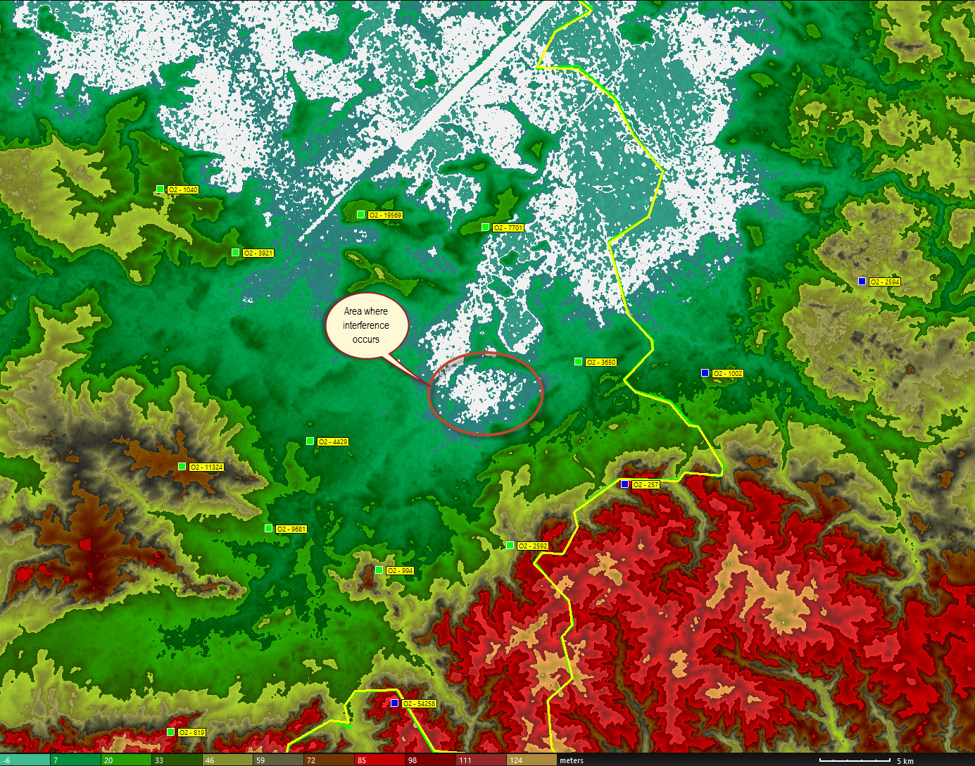
24 B.4 - Configuration 2 B Simulation results The following maps in JPG format have been provided: - "BS Pattern V Rx 419_SFN1...7.jpg": Individual SFN coverage with 2 values. 0 for interference and 1 for coverage without interference. - "BS Pattern V Rx 419_SFN_Combination.jpg": Combination of all SFN coverage with 2 values. 0 for interference (no SFN is available without interference) and 1 when at least 1 SFN is covering without interference. - "BS Pattern V Rx 419_SFN4 global coverage map": Combination of all SFN coverage showing where SFN4 is covering and where other SFNs are covering, plus interference areas. - "BS Pattern V Rx 419_SFN4 overlapping coverage map.jpg": Combination of all SFN coverage showing where SFN4 is covering alone, where SFN 4 is covering with another SFN, and where other SFNs are covering, plus interference areas. - "BS Pattern V Rx 419_SFN4 overlapping coverage map_number of SFN received.jpg": Combination of all SFN coverage showing how many SFNs are covering each point plus interference areas. The analysis of the SFN 4 coverage map is showing that 93.3% of the SFN 4 polygon is covered without interference with 6.7% of interfered area. When considering the combination of all SFNs, the interference areas are reduced to 0.38% of SFN 4 polygon with 99.62% of coverage without interference. The analysis of the interfered area is made in the next section. 24/44
25 B Analysis of interfered areas in SFN 4 ploygon Interference areas are located into a basin and is at the edge of SFN 4 & SFN 3 coverage. The table below lists the main signals received inside the interference plot. Callsign SFN # Address Status FSR dbuv/m Pr dbm ToA us Delta TOA Frequency MHz Polar Distance m Azimuth (deg) Tilt (deg) 3650 SFN4 TL Wanted H SFN3 TL MFN interferer H SFN4 TL SFN H SFN4 TL SFN H SFN4 TL SFN H SFN3 TL MFN interferer H SFN3 TL MFN interferer H SFN4 TL SFN H SFN4 TL SFN H SFN4 TL SFN H SFN4 TL SFN H SFN4 TL SFN H SFN3 TL MFN interferer H SFN4 TL SFN H SFN4 TL SFN H Rx antenna (m) It has to be noted that only MFN interference occurs. There is no SFN interference. 25/44
26 26/44

27 27/44
28 Terrain profiles From O (wanted) to the interference area 28/44
29 From 257 (strongest MFN interferer) to the interference area 29/44
30 From 1002 (MFN interferer) to the interference area 30/44
31 From (MFN interferer) to the interference area 31/44

32 From 2594 (MFN interferer) to the interference area 32/44
33 So interference is coming from base stations that are located on high points with visibility or very close to visibility conditions to the interference areas. As detailed in the following table, interference mainly occurs outside urban clutters: SFN 4 Combination coverage Total area km² Urban Clutter area km² Other Clutters area km² Total area covered Urban Clutters covered Other Clutters covered Total interfered and noncovered area Interfered and non-covered area over urban Clutters Interfered and non-covered area over other Clutters Configuration % 99.86% 99.57% 0.38% 0.14% 0.43% Possible solutions are proposed in Part C of this document. B.5 - Configuration 3 In order to have an idea of the TV antennas that will need to be re-oriented in order to receive the LPLT service in SFN mode. The assumption made is that all antennas of all SFNs are oriented towards the center of SFN 4 area. Two maps have been provided in JPG format: - "BS V pattern Rx 419 Oriented_SFN4.jpg": Individual SFN coverage with 2 values. 0 for interference and 1 for coverage without interference. - "BS V pattern Rx 419 Oriented_SFN_Combination.jpg": Combination of all SFN coverage with 2 values. 0 for interference (no SFN is available without interference) and 1 when at least 1 SFN is covering without interference. The analysis of the SFN 4 coverage map is showing that 87.1% of the SFN 4 polygon is covered without interference with 12.9% of interfered area. When considering the combination of all SFNs, the interference areas are reduced to 11.58% of SFN 4 polygon with 88.42% of coverage without interference. Compared to Configuration 2 results (0.38% of interference inside SFN 4 polygon of with 99.62% of coverage without interference), it means that around 10% pf the antennas will have to be reoriented. B.6 - Configuration 4 In order to improve the SFN 4 coverage, the ITU-R BT.419 standard antenna is replaced by a High Performance antenna manufactured by Qualcomm. 33/44
34 The following maps in JPG format have been provided: - "BS Pattern V Rx HP_SFN1..7.jpg": Individual SFN coverage with 2 values. 0 for interference and 1 for coverage without interference. - "BS Pattern V Rx HP_SFN_Combination.jpg": Combination of all SFN coverage with 2 values. 0 for interference (no SFN is available without interference) and 1 when at least 1 SFN is covering without interference. - "BS Pattern V Rx HP_SFN4 global coverage map.jpg": Combination of all SFN coverage showing where SFN4 is covering and where other SFNs are covering, plus interference areas. - "BS Pattern V Rx HP_SFN4 overlapping coverage map.jpg": Combination of all SFN coverage showing where SFN4 is covering alone, where SFN 4 is covering with another SFN, and where other SFNs are covering, plus interference areas. - "BS Pattern V Rx HP_SFN4 overlapping coverage map_number of SFN received.jpg": Combination of all SFN coverage showing how many SFNs are covering each point plus interference areas. The analysis of the SFN 4 coverage map is showing that 95.66% of the SFN 4 polygon is covered without interference with 4.34% of interfered area. When considering the combination of all SFNs, the interference areas are reduced to 0.1% of SFN 4 polygon with 99.9% of coverage without interference. The interference araes are then very limited and covering a very small amount of Urban clutters: SFN 4 Combination coverage Total area km² Urban Clutter area km² Other Clutters area km² Total area covered Urban Clutters covered Other Clutters covered Total interfered and noncovered area Interfered and non-covered area over urban Clutters Interfered and non-covered area over other Clutters Configuration % 99.89% 99.97% 0.10% 0.11% 0.03% The use of High Performance antennas is highly improving the interference problem. B.7 - Configuration 7 Using the same fixed network of base stations, the mobile reception is then analyzed. The following maps in JPG format have been provided: - "BS Pattern V Rx Mobile_SFN jpg": Individual SFN coverage with 2 values. 0 for interference and 1 for coverage without interference. - "BS Pattern V Rx Mobile_SFN combination.jpg ": Combination of all SFN coverage with 2 values. 0 for interference (no SFN is available without interference) and 1 when at least 1 SFN is covering without interference. 34/44
35 - "BS Pattern V Rx Mobile_SFN4 Global coverage map.jpg ": Combination of all SFN coverage showing where SFN4 is covering and where other SFNs are covering, plus interference areas. - "BS Pattern V Rx Mobile_SFN4 overlapping coverage map.jpg ": Combination of all SFN coverage showing where SFN4 is covering alone, where SFN 4 is covering with another SFN, and where other SFNs are covering, plus interference areas. - "BS Pattern V Rx Mobile_SFN4 overlapping coverage map_number of SFN received.jpg ": Combination of all SFN coverage showing how many SFNs are covering each point plus interference areas. The analysis of the SFN 4 coverage map is showing that 72.18% of the SFN 4 polygon is covered without interference with 22.25% of interfered area and 5.57% of non-covered area. When considering the combination of all SFNs, the interference and non-covered areas are reduced to 24.45% of SFN 4 polygon with 75.55% of coverage without interference. The mobile reception would need to be improved but is already achieving a rather good quality of service at this stage. Part C - Local optimization in difficult areas When considering the coverage results achieved in Configuration 4, the fixed reception is almost perfect inside SFN4 contour, except in the following 2 areas at the border between SFN 3 and SFN 4: 35/44
36 In order to improve the situation, 2 optimization configurations have been studied: Configuration 5 Configuration 6 Base stations Omnidirectional in H plane and vertical pattern according to ITU-R Optimized configuration V1 Omnidirectional in H plane and vertical pattern according to ITU-R Optimized configuration V2 Terminal Advanced fixed antenna from Qualcomm 10m AGL Advanced fixed antenna from Qualcomm 10m AGL C.1 - Configuration 5 A first optimization step has been performed from Configuration 4. The network improvements have been made on the 2 local areas listed above with the following configuration: - " 797" station has been sectorized with 2 sectors with 120 aperture in the horizontal pattern based on ITU-R 1336 standard antenna. One sector pointing to 90 and the other to /44

37 - " 257" station has been sectorized with 2 sectors with 180 aperture in the horizontal pattern based on ITU-R 1336 standard antenna. One sector pointing to 120 belonging to SFN 3 and the other pointing to 300 belonging to SFN 4. 37/44


38 - " 54258" station originally belonging to SFN 3 has been sectorized with 3 sectors, one towards SFN 3 and 2 towards SFN 4 with 120 aperture. Same 120 pattern as above. 38/44
39 Sector pointing to 180 belonging to SFN 3 and sectors pointing to 60 and 300 belonging to SFN 4. - A new station has been added ( W radiated power, 600MHz): Longitude Latitude Altitude Antenna height AGL Callsign SFN ID 4DMS 4DMS (m) (m) Add E N SFN 4 The following maps in JPG format have been provided: 39/44
40 - "BS Pattern V Rx HP_SFN1..7.jpg": Individual SFN coverage with 2 values. 0 for interference and 1 for coverage without interference. - "BS Pattern V 1336 Optim - Rx HP _SFN_Combination.jpg": Combination of all SFN coverage with 2 values. 0 for interference (no SFN is available without interference) and 1 when at least 1 SFN is covering without interference. The analysis of the SFN 4 coverage map is showing that 96.55% of the SFN 4 polygon is covered without interference with 3.45% of interfered area. When considering the combination of all SFNs, the interference areas are reduced to 0.63% of SFN 4 polygon with 99.37% of coverage without interference. Interference on the combination map is mainly around the sectorized antennas due to a front to back ratio that is not enough to remove interference between adjacent sectors belonging to different SFNs. 40/44
41 Compared to Configuration 4, the SFN 4 coverage considered alone is a bit improved, but the coverage without interference in the when considering the combination of all SFNs is a bit worse than the original network. Another improvement is then considered in Configuration 6. C.2 - Configuration 6 Another optimization step has been conducted from Configuration 5 with the following modifications: - Only one sector of original station " 257" station has been considered with 180 aperture pointing towards SFN 3 in azimuth Only the 2 sectors of the 3 made from " 54258" original station are considered. Sector pointing towards SFN 3 has been removed, keeping 2 sectors pointing towards SFN 4 in azimuths 60 and 300 with 120 aperture. 41/44
42 The following maps in JPG format have been provided: - "BS Pattern V Rx HP_SFN1 and 2.jpg": Individual SFN coverage with 2 values. 0 for interference and 1 for coverage without interference. - "BBS Pattern V 1336 Optim - Rx HP V2_SFN3+4_Combination.jpg": Combination of SFN 3 and SFN 4 coverage with 2 values. 0 for interference (no SFN is available without interference) and 1 when at least 1 SFN is covering without interference. The analysis of the SFN 4 coverage map is showing that 97.27% of the SFN 4 polygon is covered without interference with 2.73% of interfered area. 42/44
43 With this configuration, SFN 4 single coverage is improved compared to Configuration 5 but more important, it demonstrates that local optimization is possible by adding sites or reconfiguring sectors that will solve local interference problems. Part D - Overall analysis of the solution studied The study has demonstrated that: As expected, the SFN coverage with the use of LPLT SFN networks and existing mobile sites is perfectly received inside each SFN contours with fixed reception. 43/44
44 With the same configuration of sites used for fixed reception, the results achieved for the mobile reception are encouraging. The quality of service is lower than the one of the fixed reception but could be improved by adding more sites Interference problems are occurring at the border of two different SFNs and are exclusively coming from other SFNs (MFN interference). With the help of 200µs cyclic prefix, there is no intra SFN interference. So, with the use of an advanced fixed antenna, interference levels are highly reduced, but not completely removed in some local areas. And interference areas are mainly located outside urban Clutters. Finally, we have seen that adjusting SFN coverage contours to the administrative contours with the help of local optimization, as seen in Configuration 6, is necessary. So that adding sites where the coverage is poor and interfered is a good option. And using sectorized sites with appropriate azimuth orientation is also a good way to reduce local interference problems. 44/44
Interference from future mobile network services in frequency band 790 862 MHz to digital TV in frequencies below 790 MHz.
 2009-02-05 Interference from future mobile network services in frequency band 790 862 MHz to digital TV in frequencies below 790 MHz. TABLE OF CONTENTS 1 SUMMARY...3 2 BACKGROUND /INTRODUCTION...3 3 APPROACH,
Characteristics of terrestrial IMT-Advanced systems for frequency sharing/ interference analyses
 Report ITU-R M.2292-0 (12/2013) Characteristics of terrestrial IMT-Advanced systems for frequency sharing/ interference analyses M Series Mobile, radiodetermination, amateur and related satellite services
COMPATIBILITY STUDY FOR UMTS OPERATING WITHIN THE GSM 900 AND GSM 1800 FREQUENCY BANDS
 Electronic Communications Committee (ECC) within the European Conference of Postal and Telecommunications Administrations (CEPT) COMPATIBILITY STUDY FOR UMTS OPERATING WITHIN THE GSM 900 AND GSM 1800 FREQUENCY
DVB-T and Wireless Microphone Exclusion Area Computation Through Interference Analysis
 SE43(11)Info 12 DVB-T and Wireless Microphone Exclusion Area Computation Through Interference Analysis Rogério Dionísio Instituto de Telecomunicações - Portugal 11th SE43 meeting, 19 September 2011 Page
DVB-SH. Radio Network Planning Tool. (Release 4.2)
") DVB-SH Radio Network Planning Tool (Release 4.2) by AWE Communications GmbH. All rights reserved 1 1 Introduction 1.1 Overview Digital Video Broadcasting Satellite to Handheld (DVB-SH) aims to provide
DVB-SH Radio Network Planning Tool (Release 4.2) by AWE Communications GmbH. All rights reserved 1 1 Introduction 1.1 Overview Digital Video Broadcasting Satellite to Handheld (DVB-SH) aims to provide
COMPATIBILITY AND SHARING ANALYSIS BETWEEN DVB T AND RADIO MICROPHONES IN BANDS IV AND V
 European Radiocommunications Committee (ERC) within the European Conference of Postal and Telecommunications Administrations (CEPT) COMPATIBILITY AND SHARING ANALYSIS BETWEEN DVB T AND RADIO MICROPHONES
An Algorithm for Automatic Base Station Placement in Cellular Network Deployment
 An Algorithm for Automatic Base Station Placement in Cellular Network Deployment István Törős and Péter Fazekas High Speed Networks Laboratory Dept. of Telecommunications, Budapest University of Technology
PROTECTION OF THE BROADCASTING SERVICE FROM BROADCASTING SATELLITE SERVICE TRANSMISSIONS IN THE BAND 620 790 MHz
 Electronic Communications Committee (ECC) within the European Conference of Postal and Telecommunications Administrations (CEPT) PROTECTION OF THE BROADCASTING SERVICE FROM BROADCASTING SATELLITE SERVICE
Report for GSMA on the Coexistence of ISDB-T and LTE W1306L4205. Access Networks Lead Engineer. Issue Date 15 th January 2014
 Coexistence of Proposal Author: Appointment: Paul Grant Access Networks Lead Engineer Approved: Appointment: Nick Kirkman Technical Director Issue Date 15 th January 2014 Advanced Topographic Development
ENTERPRISE. Functionality chart
 ENTERPRISE Functionality chart Cellular Expert Enterprise module features Tasks Network data management Site, sector, construction, customer, repeater management: Add Edit Move Copy Delete Site re-use
Omni Antenna vs. Directional Antenna
 Omni Antenna vs. Directional Antenna Document ID: 82068 Contents Introduction Prerequisites Requirements Components Used Conventions Basic Definitions and Antenna Concepts Indoor Effects Omni Antenna Pros
Electronic Communications Committee (ECC) within the Conference of Postal and Telecommunications Administrations (CEPT)
 within the Conference of Postal and Telecommunications Administrations (CEPT)") Page 1 Electronic Communications Committee (ECC) within the Conference of Postal and Telecommunications Administrations (CEPT) ECC RECOMMENDATION (05)08 (replacing recommendations T/R 20-08 and 22-07)
Page 1 Electronic Communications Committee (ECC) within the Conference of Postal and Telecommunications Administrations (CEPT) ECC RECOMMENDATION (05)08 (replacing recommendations T/R 20-08 and 22-07)
Potential Effects of Wind Turbine Generators on Pre-Existing RF Communication Networks SEAN YUN. June 2009. Software Solutions in Radiocommunications
 Potential Effects of Wind Turbine Generators on Pre-Existing RF Communication Networks June 2009 SEAN YUN 2 2 Abstract In an effort to help preserve the ozone and the availability of diminishing natural
700 and 800 MHz Band Slot Antennas
 Low Group Delay, Wide Bandwidth UHF Slot Antennas Omni-directional and Directional Patterns Available Low RFR Models Available Top or Side Mount Models Horizontal, Elliptical, or Circular Polarization
International co-ordination of DVB-T frequencies in Europe
 ITU-D Seminar Kiev, 13-15 November 2000 THE TRANSITION FROM SECAM TO DIGITAL BROADCASTING International co-ordination of DVB-T frequencies in Europe By J. Doeven; Nozema, The Netherlands 1. Introduction
White Paper: Microcells A Solution to the Data Traffic Growth in 3G Networks?
 White Paper: Microcells A Solution to the Data Traffic Growth in 3G Networks? By Peter Gould, Consulting Services Director, Multiple Access Communications Limited www.macltd.com May 2010 Microcells were
Antenna Deployment Technical Brief
 ProCurve Networking Antenna Deployment Technical Brief Introduction... 2 Antenna types... 2 Omni directional antennas... 2 Directional antennas... 2 Diversity antennas... 3 High gain directional antennas...
MEDIA TECHNOLOGY & INNOVATION. General issues to be considered when planning SFNs
 EBU TECHNICAL MEDIA TECHNOLOGY & INNOVATION 13/03/09 General issues to be considered when planning SFNs 1. SFN networks In a Single Frequency Network (SFN), all transmitters in the network use the same
Planning Terrestrial Radio Networks
 Planning Terrestrial Radio Networks Lab Exercise Manual IK2500 - Radio Communication, Basic Course September 23, 2008 Short Summary The scope of this lab is to help students to develop basic skills in
P25 / TETRA Network Planning Using EDX SignalPro
 P25 / TETRA Network Planning Using EDX SignalPro P25 / TETRA Network Planning Using EDX SignalPro Ted Hicks, VP Engineering EDX Wireless February, 2013 Introduction Public Safety wireless networks are
The road and the buildings on each side of the road can
 Alternative RF Planning Solutions for Coverage Deficiency Aleksey A. Kurochkin [email protected] Issue Date: December 2002 INTRODUCTION This paper introduces a few of the more common alternatives to
TECHNICAL ARRANGEMENT. ON BORDER COORDINATION OF BROADBAND SYSTEMS (UMTS, LTE AND WiMAX) IN THE 900 MHZ BAND
 IN THE 900 MHZ BAND") TECHNICAL ARRANGEMENT BETWEEN THE NATIONAL FREQUENCY MANAGEMENT AUTHORITIES OF AUSTRIA, CROATIA, HUNGARY, ROMANIA, SERBIA, THE SLOVAK REPUBLIC AND SLOVENIA ON BORDER COORDINATION OF BROADBAND SYSTEMS (UMTS,
TECHNICAL ARRANGEMENT BETWEEN THE NATIONAL FREQUENCY MANAGEMENT AUTHORITIES OF AUSTRIA, CROATIA, HUNGARY, ROMANIA, SERBIA, THE SLOVAK REPUBLIC AND SLOVENIA ON BORDER COORDINATION OF BROADBAND SYSTEMS (UMTS,
RECOMMENDATION ITU-R F.1113. (Question ITU-R 157/9) b) that systems using this mode of propagation are already in service for burst data transmission,
 b) that systems using this mode of propagation are already in service for burst data transmission,") Rec. ITU-R F.1113 1 RECOMMENDATION ITU-R F.1113 RADIO SYSTEMS EMPLOYING METEOR-BURST PROPAGATION (Question ITU-R 157/9) (1994) Rec. ITU-R F.1113 The ITU Radiocommunication Assembly, considering a) that
Rec. ITU-R F.1113 1 RECOMMENDATION ITU-R F.1113 RADIO SYSTEMS EMPLOYING METEOR-BURST PROPAGATION (Question ITU-R 157/9) (1994) Rec. ITU-R F.1113 The ITU Radiocommunication Assembly, considering a) that
RSPG public consultation related to the draft opinion on EU spectrum policy implications of the digital dividend.
 RSPG public consultation related to the draft opinion on EU spectrum policy implications of the digital dividend Vodafone comments Vodafone welcomes the opportunity to comment on the draft RSPG Opinion
SHARING BETWEEN TERRESTRIAL FLIGHT TELEPHONE SYSTEM (TFTS) AND RADIO ASTRONOMY IN THE 1.6 GHz BAND. Paris, May 1992
 AND RADIO ASTRONOMY IN THE 1.6 GHz BAND. Paris, May 1992") European Radiocommunications Committee (ERC) within the European Conference of Postal and Telecommunications Administrations (CEPT) SHARING BETWEEN TERRESTRIAL FLIGHT TELEPHONE SYSTEM (TFTS) AND RADIO
European Radiocommunications Committee (ERC) within the European Conference of Postal and Telecommunications Administrations (CEPT) SHARING BETWEEN TERRESTRIAL FLIGHT TELEPHONE SYSTEM (TFTS) AND RADIO
GSM frequency planning
 GSM frequency planning Band : 890-915 and 935-960 MHz Channel spacing: 200 khz (but signal bandwidth = 400 khz) Absolute Radio Frequency Channel Number (ARFCN) lower band: upper band: F l (n) = 890.2 +
MIMO Antenna Systems in WinProp
 MIMO Antenna Systems in WinProp AWE Communications GmbH Otto-Lilienthal-Str. 36 D-71034 Böblingen [email protected] Issue Date Changes V1.0 Nov. 2010 First version of document V2.0 Feb. 2011
ADJACENT AND CO-CHANNEL INTERFERENCE DISTURBANCES FROM A DIGITAL TERRESTRIAL TELEVISION SIGNAL(COFDM-8K System) ON ANALOGUE PAL SYSTEMS
 ON ANALOGUE PAL SYSTEMS") ADJACENT AND CO-CHANNEL INTERFERENCE DISTURBANCES FROM A DIGITAL TERRESTRIAL TELEVISION SIGNAL(COFDM-8K System) ON ANALOGUE PAL SYSTEMS A. Arrinda ([email protected]), M. Mª Vélez, P. Angueira, D. de
ADJACENT AND CO-CHANNEL INTERFERENCE DISTURBANCES FROM A DIGITAL TERRESTRIAL TELEVISION SIGNAL(COFDM-8K System) ON ANALOGUE PAL SYSTEMS A. Arrinda ([email protected]), M. Mª Vélez, P. Angueira, D. de
Evaluation of Co-existence interference between CDMA 1900MHz & WCDMA 2100MHz
 Evaluation of Co-existence interference between CDMA 1900MHz & 2100MHz October 2007 Detailed interference analysis report prepared by AUSPI for co-existence of CDMA/EVDO & GSM/ in 1900MHz frequency band
Selecting Receiving Antennas for Radio Tracking
 Selecting Receiving Antennas for Radio Tracking Larry B Kuechle, Advanced Telemetry Systems, Inc. Isanti, Minnesota 55040 [email protected] The receiving antenna is an integral part of any radio location
Small-Cell Wireless Backhauling
 Small-Cell Wireless Backhauling A Non-Line-of-Sight Approach for Point-to-Point Microwave Links M. Coldrey*, H. Koorapaty**, J.-E. Berg***, Z. Ghebretensaé***, J. Hansryd****, A. Derneryd*, S. Falahati***
Downlink Performance of WiMAX Broadband from High Altitude Platform and Terrestrial Deployments sharing a common 3.5GHz band
 Downlink Performance of WiMAX Broadband from igh Altitude Platform and Terrestrial Deployments sharing a common 3.5Gz band Z. Yang, D. Grace, P. D. Mitchell Communications Research Group, Department of
Avaya WLAN 9100 External Antennas for use with the WAO-9122 Access Point
 Avaya WLAN 9100 External Antennas for use with the WAO-9122 Access Point Overview To optimize the overall performance of a WLAN in an outdoor deployment it is important to understand how to maximize coverage
Inter-Cell Interference Coordination (ICIC) Technology
 Technology") Inter-Cell Interference Coordination (ICIC) Technology Dai Kimura Hiroyuki Seki Long Term Evolution (LTE) is a promising standard for next-generation cellular systems targeted to have a peak downlink bit
Inter-Cell Interference Coordination (ICIC) Technology Dai Kimura Hiroyuki Seki Long Term Evolution (LTE) is a promising standard for next-generation cellular systems targeted to have a peak downlink bit
Jim Seymour, Ph.D. Principal Engineer Mobility CTO Group Cisco Systems Inc. August 2015. 2011 Cisco and/or its affiliates. All rights reserved.
 Jim Seymour, Ph.D. Principal Engineer Mobility CTO Group Cisco Systems Inc. August 215 1 Outline Global Mobile Data Growth Trends (Cisco VNI data) Studies of Real-Time, Delay Sensitive Video over LTE Global
Understanding Range for RF Devices
 Understanding Range for RF Devices October 2012 White Paper Understanding how environmental factors can affect range is one of the key aspects to deploying a radio frequency (RF) solution. This paper will
Evolution in Mobile Radio Networks
 Evolution in Mobile Radio Networks Multiple Antenna Systems & Flexible Networks InfoWare 2013, July 24, 2013 1 Nokia Siemens Networks 2013 The thirst for mobile data will continue to grow exponentially
Antenna Comparison. Version 1.0 By Holger Raeder
 Antenna Comparison Version 1.0 By Holger Raeder This paper provides analysis results based on four types of antenna comparisons, which include the following: Standard gain antenna vs. high gain antenna
RESULTS OF TESTS WITH DOMESTIC RECEIVER IC S FOR DVB-T. C.R. Nokes BBC R&D, UK ABSTRACT
 RESULTS OF TESTS WITH DOMESTIC RECEIVER IC S FOR DVB-T C.R. Nokes BBC R&D, UK ABSTRACT Digital terrestrial television services using the DVB-T standard will be launched later this year in the UK, followed
LTE Evolution for Cellular IoT Ericsson & NSN
 LTE Evolution for Cellular IoT Ericsson & NSN LTE Evolution for Cellular IoT Overview and introduction White Paper on M2M is geared towards low cost M2M applications Utility (electricity/gas/water) metering
Cellular Wireless Antennas
 Cellular Wireless Antennas A Technical Brief GarrettCom Inc., November 2010 Overview The Cellular Wireless Antenna Technical brief is provided to assist with the design and deployment of the DX940 Cellular
General Survey of Radio Frequency Bands 30 MHz to 3 GHz
 General Survey of Radio Frequency Bands 30 MHz to 3 GHz Version 2.0 September 23, 2010 Prepared by: Shared Spectrum Company 1595 Spring Hill Road Suite 110 Vienna, VA 22182-2228 703-761-2818 Fax: 703-761-2817
Definition of Traffic for Network Planning Projects
 Definition of Traffic for Network Planning Projects AWE Communications GmbH Otto-Lilienthal-Straße 36 D-71034 Böblingen [email protected] Issue Date Changes V0.1 Oct. 2012 First version of document V1.0
RECOMMENDATION ITU-R P.1546-1. Method for point-to-area predictions for terrestrial services in the frequency range 30 MHz to 3 000 MHz
 Rec. ITU-R P.546- RECOMMENDATION ITU-R P.546- Method for point-to-area predictions for terrestrial services in the frequency range 30 MHz to 3 000 MHz (200-2003) The ITU Radiocommunication Assembly, considering
FREQUENCY ASSIGNMENT REQUIREMENTS FOR THE LAND MOBILE SERVICE
 RALI : LM 8 DATE OF EFFECT : 23/09/2015 Radiocommunications Assignment and Licensing Instruction FREQUENCY ASSIGNMENT REQUIREMENTS FOR THE LAND MOBILE SERVICE AUSTRALIAN COMMUNICATIONS AND MEDIA AUTHORITY
Isolation between antennas of IMT base stations in the land mobile service
 Report ITU-R M.44 (11/011) Isolation between antennas of IMT base stations in the land mobile service M Series Mobile, radiodetermination, amateur and related satellite services ii Rep. ITU-R M.44 Foreword
The Application of Land Use/ Land Cover (Clutter) Data to Wireless Communication System Design
 Data to Wireless Communication System Design") Technology White Paper The Application of Land Use/ Land Cover (Clutter) Data to Wireless Communication System Design The Power of Planning 1 Harry Anderson, Ted Hicks, Jody Kirtner EDX Wireless, LLC Eugene,
Technology White Paper The Application of Land Use/ Land Cover (Clutter) Data to Wireless Communication System Design The Power of Planning 1 Harry Anderson, Ted Hicks, Jody Kirtner EDX Wireless, LLC Eugene,
Simulation and Performance Evaluation of co-existing GSM and UMTS systems Master Thesis
 DEPARTMENT OF TECHNOLOGY AND BUILT ENVIRONMENT Simulation and Performance Evaluation of co-existing GSM and UMTS systems Master Thesis Author: Laura Cutillas Sánchez January 2010 Master s Program in Electronics/Telecommunications
Dynamics of 3GPP LTE uplink: 800 MHz DTT and LTE coexistence
 Dynamics of 3GPP LTE uplink: 800 MHz DTT and LTE coexistence Issued to: Ofcom Version: 5.0 Real Wireless Ltd PO Box 2218 Pulborough t +44 207 117 8514 West Sussex f +44 808 280 0142 RH20 4XB e [email protected]
4G LTE Opportunities & Challenges in DTT arena
 4G LTE Opportunities & Challenges in DTT arena DigiTAG Workshop Istanbul 14-15 November 2013 Stan Baaijens, CEO Funke 1 Why 4G LTE (Long Term Evolution) The unrelenting growth of smartphone and tablet
CABLES CABLES. Application note. Link Budget
 CABLES CABLES radiating Link Budget 3. 1. LINK BUDGET The basic elements to calculate a link budget can be illustrated by considering the example shown in Figure 4. It involves a GSM 900 radio coverage
ACRS 2.0 User Manual 1
 ACRS 2.0 User Manual 1 FCC Regulatory Information This device complies with part 15 of the FCC Rules. Operation is subject to the following two conditions: (1) This device may not cause harmful interference,
Convergence between Broadcast and Mobile Broadband in the UHF band -a long term vision-
 Convergence between Broadcast and Mobile Broadband in the UHF band -a long term vision- Paulo Marques, Instituto de Telecomunicacoes, Portugal, 7 th March 2014, ASPF#4, Brunei 1 Disclaimer The views and
app coverage applied EXTRACT FROM THE ERICSSON MOBILITY REPORT
 app applied EXTRACT FROM THE ERICSSON MOBILITY REPORT NOVEMBER 2013 App COVERAGE applied The use of smartphones and tablets has caused a surge in mobile data around the world. Today, users want reliable
PLANNING DVB-T2 Advance and Challenge
 Advance and Challenge This White Paper provides an overview of major techniques used in and their impact on service planning and operation of this new transmission technology. White Paper October 2010
Rec. ITU-R F.699-5 1 RECOMMENDATION ITU-R F.699-5 *
 Rec. ITU-R F.699-5 1 RECOMMENATION ITU-R F.699-5 * REFERENCE RAIATION PATTERNS FOR LINE-OF-SIGHT RAIO-RELAY SYSTEM ANTENNAS FOR USE IN COORINATION STUIES AN INTERFERENCE ASSESSMENT IN THE FREQUENCY RANGE
Radio Network Planning Tools Basics, Practical Examples & Demonstration on NGN Network Planning Part I
 Radio Network Planning Tools Basics, Practical Examples & Demonstration on NGN Network Planning Part I Roland Götz LS telcom AG Regional Seminar on evolving network infrastructures to NGN and related Planning
EE4367 Telecom. Switching & Transmission. Prof. Murat Torlak
 Path Loss Radio Wave Propagation The wireless radio channel puts fundamental limitations to the performance of wireless communications systems Radio channels are extremely random, and are not easily analyzed
Site Survey Report MAH
 Site Survey Report MAH Index 1. Introduction...3 1.1 Contact Information... 3 1.2 Scope of Survey and Spectrum... 3 1.3 Validity... 3 2. Report...4 2.1 Coverage... 4 2.1.1 Signal Strength vs. Signal to
Guidance for Business Radio
 Guidance for Business Radio Business Radio online enables users to apply for a range of licences covering the use of radio for mostly short range localised radio networks for factories, shopping centres.
REPORT ITU-R BS.1203-1 * DIGITAL SOUND BROADCASTING TO VEHICULAR, PORTABLE AND FIXED RECEIVERS USING TERRESTRIAL TRANSMITTERS IN THE UHF/VHF BANDS
 - 1 - REPORT ITU-R BS.1203-1 * DIGITAL SOUND BROADCASTING TO VEHICULAR, PORTABLE AND FIXED RECEIVERS USING TERRESTRIAL TRANSMITTERS IN THE UHF/VHF BANDS (1990-1994) This Report contains background and
5. ANTENNA TYPES. Figure 5. The vertical dipole and its electromagnetic equivalent, the vertical monopole
 Antennas can be classified in several ways. One way is the frequency band of operation. Others include physical structure and electrical/electromagnetic design. The antennas commonly used for LMR both
This Antenna Basics reference guide includes basic information about antenna types, how antennas work, gain, and some installation examples.
 Antenna Basics This Antenna Basics reference guide includes basic information about antenna types, how antennas work, gain, and some installation examples. What Do Antennas Do? Antennas transmit radio
VoIP-Kapazität im Relay erweiterten IEEE 802.16 System
 VoIP-Kapazität im Relay erweiterten IEEE 802.16 System 21. ComNets-Workshop Mobil- und Telekommunikation Dipl.-Ing. Karsten Klagges ComNets Research Group RWTH Aachen University 16. März 2012 Karsten Klagges
The Importance of the Global C-band Allocation for Satellite Communications Services
 FOUNTAIN COURT, 2 VICTORIA SQ., ST ALBANS HERTFORDSHIRE, AL1 3TF, ENGLAND TELEPHONE:+1 202 390 1885 EMAIL: [email protected] WEBSITE: www.gvf.org The Importance of the Global C-band Allocation for
Antennas & Propagation. CS 6710 Spring 2010 Rajmohan Rajaraman
 Antennas & Propagation CS 6710 Spring 2010 Rajmohan Rajaraman Introduction An antenna is an electrical conductor or system of conductors o Transmission - radiates electromagnetic energy into space o Reception
Pillbox Antenna for 5.6 GHz Band Dragoslav Dobričić, YU1AW [email protected]
 Pillbox Antenna for 5.6 GHz Band Dragoslav Dobričić, YU1AW [email protected] Introduction The pillbox or cheese antenna is made of two parallel plates which are connected to the narrow strip of parabolic
RADIO SPECTRUM POLICY GROUP. RSPG Opinion on a long-term strategy on the future use of the UHF band (470-790 MHz) in the European Union
 in the European Union") EUROPEAN COMMISSION Directorate-General for Communications Networks, Content and Technology Electronic Communications Networks and Services Radio Spectrum Policy Group RSPG Secretariat Brussels, 19 February
EUROPEAN COMMISSION Directorate-General for Communications Networks, Content and Technology Electronic Communications Networks and Services Radio Spectrum Policy Group RSPG Secretariat Brussels, 19 February
primary SURVEILLANCE 3D RADAR
 AIR TRAFFIC MANAGEMENT AIRport & ROUTE primary SURVEILLANCE 3D RADAR Supplying ATM systems around the world for more than 90 years indracompany.com AIRport & ROUTE primary SURVEILLANCE 3D RADAR Latest
Radio-frequency channel arrangements for high-capacity fixed wireless systems operating in the lower 6 GHz (5 925 to 6 425 MHz) band
 band") Recommendation ITU-R F.383-9 (02/2013) Radio-frequency channel arrangements for high-capacity fixed wireless systems operating in the lower 6 GHz (5 925 to 6 425 MHz) band F Series Fixed service ii Rec.
Recommendation ITU-R F.383-9 (02/2013) Radio-frequency channel arrangements for high-capacity fixed wireless systems operating in the lower 6 GHz (5 925 to 6 425 MHz) band F Series Fixed service ii Rec.
Model Rules for License-Exempt White Space Devices
 Model Rules for License-Exempt White Space Devices 1 Permissible Frequencies of Operation. (a) White space devices ( WSDs ) are permitted to operate on a license-exempt basis subject to the interference
DVB-T BER MEASUREMENTS IN THE PRESENCE OF ADJACENT CHANNEL AND CO-CHANNEL ANALOGUE TELEVISION INTERFERENCE
 DVB-T MEASUREMENTS IN THE PRESENCE OF ADJACENT CHANNEL AND CO-CHANNEL ANALOGUE TELEVISION INTERFERENCE M. Mª Vélez ([email protected]), P. Angueira, D. de la Vega, A. Arrinda, J. L. Ordiales UNIVERSITY
BSA Technical Information
 BSA Technical Information Electrical Isolation of Co-Located Horizontally and Vertically Stacked Antennas Introduction: Service providers are facing rapidly increasing pressure from zoning boards to co-locate
Antenna Basic Concepts
 ANTENNA An antenna is a device to transmit and/or receive electromagnetic waves. Electromagnetic waves are often referred to as radio waves. Most antennas are resonant devices, which operate efficiently
System Design in Wireless Communication. Ali Khawaja
 System Design in Wireless Communication Ali Khawaja University of Texas at Dallas December 6, 1999 1 Abstract This paper deals with the micro and macro aspects of a wireless system design. With the growing
Minimum requirements for DVB-T receiving antennas for portable indoor and portable outdoor reception
 Deutsche TV Platform Minimum requirements for DVB-T receiving antennas for portable indoor and portable outdoor reception compiled by Working Group: DVB-T launch (a working group of the Deutsche TV Platform)
Antenna Properties and their impact on Wireless System Performance. Dr. Steven R. Best. Cushcraft Corporation 48 Perimeter Road Manchester, NH 03013
 Antenna Properties and their impact on Wireless System Performance Dr. Steven R. Best Cushcraft Corporation 48 Perimeter Road Manchester, NH 03013 Phone (603) 627-7877 FAX: (603) 627-1764 Email: [email protected]
CDMA Network Planning
 CDMA Network Planning by AWE Communications GmbH www.awe-com.com Contents Motivation Overview Network Planning Module Air Interface Cell Load Interference Network Simulation Simulation Results by AWE Communications
Analysis of radio wave propagation in Lagos environs
 AMERICAN JOURNAL OF SCIENTIFIC AND INDUSTRIAL RESEARCH 2011, Science Huβ, http://www.scihub.org/ajsir ISSN: 2153-649X doi:10.5251/ajsir.2011.2.3.438.455 Analysis of radio wave propagation in Lagos environs
A. Jraifi, R. A. Laamara, A. Belhaj, and E. H. Saidi Lab/UFR-groupe Canal Propagation Radio PHE, Faculté des Sciences, Rabat, Morocco
 Progress In Electromagnetics Research C, Vol. 12, 15 25, 2010 A PROPOSAL SOLUTION FOR INTERFERENCE INTER-OPERATORS A. Jraifi, R. A. Laamara, A. Belhaj, and E. H. Saidi Lab/UFR-groupe Canal Propagation
Evolution of Satellite Communication Systems
 Mathieu DERVIN Brussels, 6th May 2015 Brussels, May 2015 Agenda I. From Sputnik to wideband satellite services: The key technological evolutions II. Increase the satellite system capacity: A global system
Divvela.Santhosh Raghava Rao [1],Sreevardhan cheerla [2]
![Divvela.Santhosh Raghava Rao [1],Sreevardhan cheerla [2]](/thumbs/24/2385990.jpg "Divvela.Santhosh Raghava Rao [1],Sreevardhan cheerla [2]") Signal Strength Enhancement Using Cellular Repeater On Three Frequency Bands For Low Signal Coverage Areas (GSM900, GSM 1800/DCS, 3G) Divvela.Santhosh Raghava Rao [1],Sreevardhan cheerla [2] [1] B.tech
Signal Strength Enhancement Using Cellular Repeater On Three Frequency Bands For Low Signal Coverage Areas (GSM900, GSM 1800/DCS, 3G) Divvela.Santhosh Raghava Rao [1],Sreevardhan cheerla [2] [1] B.tech
CNR Requirements for DVB-T2 Fixed Reception Based on Field Trial Results
 CNR Requirements for DVB-T2 Fixed Reception Based on Field Trial Results Iñaki Eizmendi, Gorka Berjon-Eriz, Manuel Vélez, Gorka Prieto, Amaia Arrinda This letter presents the C/N requirements for DVB-T2
Radio-frequency channel arrangements for fixed wireless systems operating in the 7 110-7 900 MHz band
 Recommendation ITU-R F.385-10 (03/2012) Radio-frequency channel arrangements for fixed wireless systems operating in the 7 110-7 900 MHz band F Series Fixed service ii Rec. ITU-R F.385-10 Foreword The
Planning of UMTS Cellular Networks for Data Services Based on HSDPA
 Planning of UMTS Cellular Networks for Data Services Based on HSDPA Diana Ladeira, Pedro Costa, Luís M. Correia 1, Luís Santo 2 1 IST/IT Technical University of Lisbon, Lisbon, Portugal 2 Optimus, Lisbon,
Achievable Transmission Rates and Self-Interference Channel Estimation in Hybrid Full-Duplex/Half-Duplex MIMO Relaying
 Achievable Transmission Rates and Self-Interference Channel Estimation in Hybrid Full-Duplex/Half-Duplex MIMO Relaying Dani Korpi 1, Taneli Riihonen 2,3, Katsuyuki Haneda 4, Koji Yamamoto 5, and Mikko
Figure 1: cellular system architecture
 Question 1: (30 marks) Consider a FDM cellular system with 120 cites, a frequency reuse factor of N=12, and 900 overall two-way channels. Omni-directional antennas are used: Figure 1 shows some of the
Technical Advisory Group
 0 Technical Advisory Group 8th October 2015 1 Visitor information Wi-fi network Ofcom Media - Password COTDsaT2HN (case sensitive) Prompted to Sign in to Wi-Fi network Agree to Terms of Use Press Continue
REPORT ITU-R M.2109. Rep. ITU-R M.2109 1 (2007)
") Rep. ITU-R M.2109 1 REPORT ITU-R M.2109 Sharing studies between IMT-Advanced systems and geostationary satellite networks in the fixed-satellite service in the 3 400-4 200 and 4 500-4 800 MHz frequency
Rep. ITU-R M.2109 1 REPORT ITU-R M.2109 Sharing studies between IMT-Advanced systems and geostationary satellite networks in the fixed-satellite service in the 3 400-4 200 and 4 500-4 800 MHz frequency
Introduction to RF Engineering. Andrew CLEGG
 Introduction to RF Engineering Andrew CLEGG 1 Comparing the Lingo Radio Astronomers Speak a Unique Vernacular We are receiving interference from your transmitter at a level of 10 janskys What the ^#$&
Interference Analysis of a Total Frequency Hopping GSM Cordless Telephony System 1
 Interference Analysis of a Total Frequency Hopping GSM Cordless Telephony System 1 Jürgen Deißner, André Noll Barreto, Ulrich Barth*, and Gerhard Fettweis Endowed Chair for Mobile Communications Systems
Antenna Trainer EAN. www.edibon.com. Technical Teaching Equipment INTRODUCTION
 Antenna Trainer EAN Technical Teaching Equipment Products Products range Units 3.-Communications INTRODUCTION Antennas are the main element of aerial communications. They are the transition between a transmission
FURTHER READING: As a preview for further reading, the following reference has been provided from the pages of the book below:
 FURTHER READING: As a preview for further reading, the following reference has been provided from the pages of the book below: Title: Cellular/PCS Management Author: Paul Beddel Publisher: McGraw-Hill
Chapter 4 Solution to Problems
 Chapter 4 Solution to Problems Question #1. A C-band earth station has an antenna with a transmit gain of 54 db. The transmitter output power is set to 100 W at a frequency of 6.100 GHz. The signal is
THE FUTURE OF TERRESTRIAL BROADCASTING IN TURKEY. DigiTAG 19th General Assembly 17th December 2014 EBU Headquarters GENEVA
 THE FUTURE OF TERRESTRIAL BROADCASTING IN TURKEY DigiTAG 19th General Assembly 17th December 2014 EBU Headquarters GENEVA THE FUTURE OF TERRESTRIAL BROADCASTING IN TURKEY Pepared by: Muhsin Kilic Head