GWHN07EANK3A1A GWHN09EANK3A1A
|
|
|
- Britton Grant
- 10 years ago
- Views:
Transcription
1 HUMMER GWHN07EANK3AA GWHN09EANK3AA

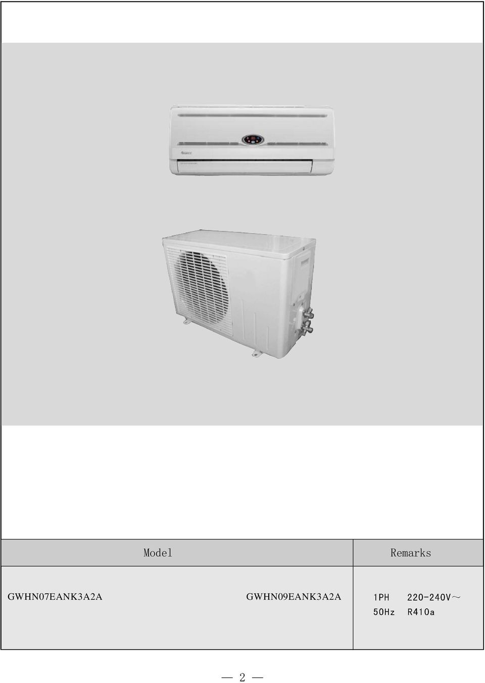
2 GWHN07EANK3A2A GWHN09EANK3A2A
3 HUMMER GWHN2EBNK3AA/I GWHN2EBNK3A2A/I GWHN2EBNK3AA GWHN2EBNK3A2A

4

5 HUMMER Model Remarks

6 2 Model Function Rated Voltage Rated Frequency Total Capacity (W) Power Input (W) Rated Input (W) Rated Current (A) Air Flow Volume (m 3 /h) Dehumidifying Volume (l/h) C.O.P / EER (W/W) Indoor unit Model of Indoor Unit Fan Motor Speed (r/min) (H/M/L) Output of Fan Motor (w) Input of Heater (w) Fan Motor Capacitor (uf) Fan Motor RLA(A) Fan Type-Piece Diameter-Length (mm) Evaporator Pipe Diameter (mm) Row-Fin Gap(mm) Coil length (l) x height (H) x coil width (L) Swing Motor Model Output of Swing Motor (W) Fuse (A) Sound Pressure Level db (A) (H/M/L) Sound Power Level db (A) (H/M/L)*** Dimension (W/H/D)( mm) Dimension of Package (L/W/H)( mm) GWHN07EANK3AA OR GWHN09EANK3AA OR GWHN07EANK3A2A GWHN09EANK3A2A COOLING HEATING COOLING HEATING V V 50Hz 50Hz 236W(7900Btu/h) 2500W(8500Btu/h) 2637W(9000Btu/h) 2785W(9500Btu/h) /-/-/- 420/-/-/ / /3.22 GWHN07EANK3AA/I (OR GWHN09EANK3AA/I (OR GWHN07EANK3A2A/I) GWHN09EANK3A2A/I) 060/960/860/760 8 / 0.2 Cross flow fan 97*538 Aluminum fin-copper tube *25.4*228.6 MP24BA.5 PCB 3.5A 38/35/32/28 48/45/42/38 70X250X80 755X260X35 060/960/860/760 8 / 0.2 Cross flow fan 97*538 Aluminum fin-copper tube *25.4*228.6 MP24BA.5 PCB 3.5A 38/35/32/28 48/45/42/38 70X250X80 755X260X35
 (H/M/L)*** Dimension (W/H/D)( mm) Dimension of Package (L/W/H)( mm) GWHN07EANK3AA OR GWHN09EANK3AA OR GWHN07EANK3A2A GWHN09EANK3A2A COOLING HEATING COOLING HEATING 220-240V 220-240V 50Hz")
7 HUMMER Model of Outdoor Unit Compressor Model Compressor Type L.R.A. (A) Compressor RLA(A) Compressor Power Input(W) Overload Protector GWHN07EANK3AA/O GWHN09EANK3AA/O QXA-B02uC30 QXA-B06uC30 Rotory Rotory B H B H Outdoor unit Connecti on Pipe Throttling Method Starting Method Working Temp Range () Condenser Pipe Diameter (mm) Rows-Fin Gap(mm) Coil length (l) x height (H) x coil width (L) Fan Motor Speed (rpm) (H/M/L)** Output of Fan Motor (W) Fan Motor RLA(A) Fan Motor Capacitor (uf) Air Flow Volume of Outdoor Unit Fan Type-Piece Fan Diameter (mm) Defrosting Method Climate Type Capillary Capillary Capacitor Capacitor -5-5 Aluminum fin-copper tube Aluminum fin-copper tube *400.5* *406* Axial fan Axial fan Auto defrost Auto defrost T T I I IP24 IP24 Isolation Moisture Protection Permissible Excessive Operating Pressure for the Discharge Side(MPa) Permissible Excessive Operating Pressure for the Suction.2.2 Side(MPa) Sound Pressure Level db (A) (H/M/L) Sound Power Level db (A) (H/M/L) Dimension (W/H/D)( mm) 720X430X X430X260 Dimension of Package (L/W/H)( mm) 765X350X X350X490 Net Weight /Gross Weight (kg) 25/29 25/29 Refrigerant Charge (kg) R40a/0.53 R40a/0.7 Length (m) 4 4 Outer Diameter Max Distance Liquid Pipe (mm) Height (m) 6(/4 ) 5 6(/4 ) 5 Gas Pipe (mm) Length (m) 9.52(3/8 ) 0 2(/2 ) 0 The above data is subject to change without notice. Please refer to the nameplate of the unit.
 Fan Motor RLA(A) Fan Motor Capacitor (uf) Air Flow Volume of Outdoor Unit Fan Type-Piece Fan Diameter (mm) Defrosting Method Climate Type Capillary Capillary Capacitor Capacitor -5-5")
8 Model Function Rated Voltage Rated Frequency Total Capacity (W) Power Input (W) Rated Input (W) Rated Current (A) Air Flow Volume (m 3 /h) Dehumidifying Volume (l/h) C.O.P / EER (W/W) Model of Indoor Unit GWHN2EBNK3AA OR GWHN2EBNK3A2A COOLING 3224W(000Btu/h) V 50Hz /3.22 HEATING 3575W(2200Btu/h) GWHN2EBNK3AA/I (OR GWHN2EBNK3A2A/I) Indoor unit Fan Motor Speed (r/min) (H/M/L) Output of Fan Motor (w) Input of Heater (w) Fan Motor Capacitor (uf) Fan Motor RLA(A) Fan Type-Piece Diameter-Length (mm) Evaporator Pipe Diameter (mm) Row-Fin Gap(mm) Coil length (l) x height (H) x coil width (L) Swing Motor Model Output of Swing Motor (W) Fuse (A) Sound Pressure Level db (A) (H/M/L) Sound Power Level db (A) (H/M/L)*** Dimension (W/H/D)( mm) Dimension of Package (L/W/H)( mm) Net Weight /Gross Weight (kg) 200/00/980/ / 0.28 Cross flow fan 97*583 Aluminum fin-copper tube *25.4*228.6 MP24BA.5 PCB 3.5A 40/38/35/3 50/48/45/4 770X250X80 80X278X /2
 Evaporator Pipe Diameter (mm) Row-Fin Gap(mm) Coil length (l) x height (H) x coil width (L) Swing Motor Model Output of Swing Motor (W) Fuse (A) Sound Pressure Level db (A) (H/M/L) Sound Power")
9 HUMMER Outdoor unit Connecti on Pipe Model of Outdoor Unit Compressor Model Compressor Type L.R.A. (A) Compressor RLA(A) Compressor Power Input(W) Overload Protector Throttling Method Starting Method Working Temp Range () Condenser Pipe Diameter (mm) Rows-Fin Gap(mm) Coil length (l) x height (H) x coil width (L) Fan Motor Speed (rpm) (H/M/L)** Output of Fan Motor (W) Fan Motor RLA(A) Fan Motor Capacitor (uf) Air Flow Volume of Outdoor Unit Fan Type-Piece Fan Diameter (mm) Defrosting Method Climate Type Isolation Moisture Protection Permissible Excessive Operating Pressure for the Discharge Side(MPa) Permissible Excessive Operating Pressure for the Suction Side(MPa) Sound Pressure Level db (A) (H/M/L) Sound Power Level db (A) (H/M/L) Dimension (W/H/D)( mm) Dimension of Package (L/W/H)( mm) Net Weight /Gross Weight (kg) Refrigerant Charge (kg) Length (m) Liquid Pipe (mm) Outer Diameter Gas Pipe (mm) Height (m) Max Distance Length (m) GWHN2EBNK3AA/O C-RV33HC Rotory B H Capillary Capacitor -5~46 Aluminum fin-copper tube *506* Axial fan 400 Auto defrost T I IP X540X X590X360 35/40 R40a/ (/4 ) 9.52(3/8 ) 5 0 The above data is subject to change without notice. Please refer to the nameplate of the unit.
 Permissible Excessive Operating Pressure for the Suction Side(MPa) Sound Pressure Level")
10 Model Function Rated Voltage Rated Frequency Total Capacity (W) Power Input (W) Rated Input (W) Rated Current (A) Air Flow Volume (m 3 /h) Dehumidifying Volume (l/h) C.O.P / EER (W/W) Indoor unit Model of Indoor Unit Fan Motor Speed (r/min) (H/M/L) Output of Fan Motor (w) Input of Heater (w) Fan Motor Capacitor (uf) Fan Motor RLA(A) Fan Type-Piece Diameter-Length (mm) Evaporator Pipe Diameter (mm) Row-Fin Gap(mm) Coil length (l) x height (H) x coil width (L) Swing Motor Model Output of Swing Motor (W) Fuse (A) Sound Pressure Level db (A) (H/M/L) Sound Power Level db (A) (H/M/L)*** Dimension (W/D/H)( mm) Dimension of Package (W/D/H)( mm) Net Weight /Gross Weight (kg) COOLING GWHN8EDNK3A2A HEATING V 50Hz /500/ / 3.0 GWHN8EDNK3A2A/I 250/080/ uf 0.2 Cross flow fan 92 X 66 Aluminum fin-copper tube X324X25.4 MP24BA 2 PCB 3.5A Transformer 0.2A 43/39/33 53/49/43 830X285X X 370 X 285 /4
 (H/M/L)*** Dimension (W/D/H)( mm) Dimension of Package (W/D/H)( mm) Net Weight /Gross Weight (kg) COOLING GWHN8EDNK3A2A HEATING 220-240V 50Hz 4500 4800 600 594 950 2000 8.47 8.")
11 HUMMER Outdoor unit Connecti on Pipe Model of Outdoor Unit Compressor Model Compressor Type L.R.A. (A) Compressor RLA(A) Compressor Power Input(W) Overload Protector Throttling Method Starting Method Working Temp Range () Condenser Pipe Diameter (mm) Rows-Fin Gap(mm) Coil length (l) x height (H) x coil width (L) Fan Motor Speed (rpm) (H/M/L)** Output of Fan Motor (W) Fan Motor RLA(A) Fan Motor Capacitor (uf) Air Flow Volume of Outdoor Unit Fan Type-Piece Fan Diameter (mm) Defrosting Method Climate Type Isolation Moisture Protection Permissible Excessive Operating Pressure for the Discharge Side(MPa) Permissible Excessive Operating Pressure for the Suction Side(MPa) Sound Pressure Level db (A) (H/M/L) Sound Power Level db (A) (H/M/L) Dimension (W/D/H)( mm) Dimension of Package (W/D/H)( mm) Net Weight /Gross Weight (kg) Refrigerant Charge (kg) Length (m) Outer Diameter Max Distance Liquid Pipe (mm) Gas Pipe (mm) Height (m) Length (m) GWHN8EDNK3A2A/O C-RV90HA Hermetic motor compressor B E Capillary Capacitor -7T43 Aluminum fin-copper tube X660X uF 2000 Axial fan 473 Auto defrost T I IP X680X X720X428 46/50 R40A/ (/4 ) 2(/2 ) 5 0 The above data is subject to change without notice. Please refer to the nameplate of the unit.
 Permissible Excessive Operating Pressure for the Suction Side(MPa) Sound Pressure Level")
12 Model Function Rated Voltage Rated Frequency Total Capacity (W) Power Input (W) Rated Input (W) Rated Current (A) Air Flow Volume (m 3 /h) Dehumidifying Volume (l/h) C.O.P / EER (W/W) Indoor unit Model of Indoor Unit Fan Motor Speed (r/min) (H/M/L) Output of Fan Motor (w) Input of Heater (w) Fan Motor Capacitor (uf) Fan Motor RLA(A) Fan Type-Piece Diameter-Length (mm) Evaporator Pipe Diameter (mm) Row-Fin Gap(mm) Coil length (l) x height (H) x coil width (L) Swing Motor Model Output of Swing Motor (W) Fuse (A) Sound Pressure Level db (A) (H/M/L) Sound Power Level db (A) (H/M/L)*** Dimension (W/D/H)( mm) Dimension of Package (W/D/H)( mm) Net Weight /Gross Weight (kg) COOLING GWHN24ECNK3A2A HEATING V~ 50Hz /670/ GWHN24ECNK3A2A/I 200/050/ / 0.4 Cross flow fan 96 X 797 Aluminum fin-copper tube X340.5X25.4 MP35XX 2.5 PCB 3.5A Transformer 0.2A 48/45/42/39 58/55/52/49 020X228X30 078X390X325 5/20
 (H/M/L)*** Dimension (W/D/H)( mm) Dimension of Package (W/D/H)( mm) Net Weight /Gross Weight (kg) COOLING GWHN24ECNK3A2A HEATING 220-240V~ 50Hz 6400 6800 2270 2260 3300 3200 4.3 3.")
13 HUMMER Outdoor unit Connecti on Pipe Model of Outdoor Unit Compressor Model Compressor Type L.R.A. (A) Compressor RLA(A) Compressor Power Input(W) Overload Protector Throttling Method Starting Method Working Temp Range () Condenser Pipe Diameter (mm) Rows-Fin Gap(mm) Coil length (l) x height (H) x coil width (L) Fan Motor Speed (rpm) (H/M/L)** Output of Fan Motor (W) Fan Motor RLA(A) Fan Motor Capacitor (uf) Air Flow Volume of Outdoor Unit Fan Type-Piece Fan Diameter (mm) Defrosting Method Climate Type Isolation Moisture Protection Permissible Excessive Operating Pressure for the Discharge Side(MPa) Permissible Excessive Operating Pressure for the Suction Side(MPa) Sound Pressure Level db (A) (H/M/L) Sound Power Level db (A) (H/M/L) Dimension (W/D/H)( mm) Dimension of Package (W/D/H)( mm) Net Weight /Gross Weight (kg) Refrigerant Charge (kg) Length (m) Outer Diameter Max Distance Liquid Pipe (mm) Gas Pipe (mm) Height (m) Length (m) GWHN24ECNK3A2A/O ASH275CV-C8LU rotary compressor Capillary Capacitor -7T43 Aluminum fin-copper tube X660X m 3 /h Axial fan 472 Auto defrost T I IP X42X700 00/450/755 59/64 R40/ The above data is subject to change without notice. Please refer to the nameplate of the unit.
 Permissible Excessive Operating Pressure for the Suction Side(MPa) Sound Pressure Level")
14 HUMMER 3 Indoor Unit Air inlet Front Panel Filter Air outlet Outdoor Unit Air inlet Air outlet

15 4 Overall and Installing Dimension of Indoor Unit Air inlet grill Left Tube-exit Sign Top View Right Tube-exit Sign Rear View Ceiling Model W(mm) H(mm) D(mm) 7K9K K
 H(mm) D(mm) 7K9K 70 250 80 2K 770")
16 HUMMER Air inlet grill Left Tube-exit Sign Top View Right Tube-exit Sign Rear View Ceiling Model W(mm) H(mm) D(mm) 7K9K K K K

17 Overall and Installing Dimension of Outdoor Unit 320 over over over over Bolt Nut Wrench

18 HUMMER Handle over over over over Bolt Nut Wrench

19 Unit over over over over Bolt Nut Wrench

20 HUMMER Unit Nut Bolt Wrench

21 5 HUMMER
22
23 6 Manual of functions of remote controller and operation method Manual of functions of remote controller for 9K,2K units 6.. Temperature parameter The room setting temperature(tpreset) The room ambient temperature (Tamb) 6..2Basic Functions Once energized, the compressor should in no way be restarted unless after 3-minute time interval at least. For the first energization, the compressor will be started without 3-minute lag. The compressor, once started,will not be stopped within 6 minutes with the change of room temperature. Cooling Mode Cooling Conditions and Process When T amb.t preset +, the unit will run under cooling mode, in which case the compressor and outdoor fan will start and the indoor fan will run at setting speed. When T amb.t preset -, the compressor and the outdoor fan will stop, the indoor fan will run at setting speed. When T preset - <T amb.< T preset +, the unit will maintain its original operating status. Under this mode, the switch valve will not be powered on, and the setting temperature range is6 ~30. T preset + T preset - T amb 6 min. 3 min. 6 min. Start cooling Original operating status Stop cooling Protection Antifreeze Protection Compressor Outdoor fan Indoor fan Run Preset speed If it is detected that the system is under antifreeze protection, the compressor and outdoor fan will be stopped, and the indoor fan will run at setting speed. When antifreeze protection is released and the compressor has stopped for 3 minutes, the unit will resume its original operating status. During antifreeze protection Stop Compressor Outdoor fan Indoor fan 3 min. Preset speed DRY Modes Run Stop The conditions and process of DRY When T amb. > Tpreset+2, the unit will run under DRY cooling mode, in which case the compressor and outdoor fan will be started and the indoor fan will run at low speed. When T preset -2T amb.t preset +2, the unit will run under DRY mode, in which case the indoor fan will keep run at low speed, the compressor and the outdoor fan will be stopped after 6 minutes. After 4 minutes,the compressor and the outdoor fan will be restarted. The dehumidifying process is so repeated in cycle. When T amb.< T preset-2, the compressor and outdoor fan will be stopped, the indoor fan will run at low speed.. Under this mode, the switchover valve will not be powered on, and the setting temperature range is6 ~30.
24 T preset +2 T preset -2 T amb 6 min. 6 min. 4 min. 4 min. Cooling Dry Stop Compressor Outdoor fan Indoor fan low speed Run Stop Protection Antifreeze Protection Upon meeting the cooling condition, if it is detected that the system is under antifreeze protection, the compressor and outdoor fan will be stopped,and the indoor fan will run at low speed. When antifreeze protection is released and the compressor has stopped for 3 minutes, the complete unit will resume its original operating status. Upon meeting the dehumidify condition, if it is detected that the system is under antifreeze protection, the com -pressor and outdoor fan will be stopped,and the indoor fan will run at low speed. When antifreeze protection is released and the compressor has stopped for 4 minutes, the complete unit will resume its original operating status HEAT Mode (there is no this mode for cooling only unit) The conditions and process of heating When Tamb Tset +2,the system enters heating running, in this case, the reversal valve, compressor, outer fan enter simultaneously running.the indoor fan will delay at most for 2min to run. When Tamb Tset +4,the compressor and outdoor fan will stop, but the reversal valve is still with power on, the indoor unit will run at setting fan speed for 60s then will stop. When Tset +2 <Tamb < Tset +4,the unit will maintain its original operating status. Under this mode, the switchover valve will be powered on, and the setting temperature range is6 ~30. Tset Tset Tamb. 6Min. 3Min. 6Min. Stop heating Original running state Start heating Compressor Outer fan Inner fan 2Min. Setting fan speed 2Min. Setting fan speed Reversal valve Conditions and processes of defrost Running Stop This unit adopt intelligent defrosting,it can defrost according to the frosting conditions,dual 8 display H Protection High Temp. Protection If it is detected that the evaporator tube temperature is too high, the outdoor fan will be stopped. When the tube temperature resumes to normal, the outdoor fan will be restarted. Noise Silencing Protection: If the unit is stopped by pressing ON/OFF, the reversal valve will be stopped after 2-minute lag; or 2 minutes will be delayed upon mode switching Fan mode Under FAN mode, only the indoor fan runs at setting speed. Compressor and outdoor fan motor stop running Auto Mode Under this mode, the system will automatically select its run mode (cool, dehumidify, heat or fan) with the change of ambient temperature. For protection function, same as under cooling and heating mode.
25 3.Other controls. Memory function Memory contents: Mode, up and down swing, Light, Setting temp., Setting fan speed, Ordinary setting Fahrenheit/Centigrade, after powered off, and powered on, it will run at the memory contents. If no timer setting function in last remote control order, the system will memorize the last remote control order, the system will memorize the last remote control order and work with last remote control setting. In the last remote control order, there is ordinary timer function, if power off happen beffore the timer arrived, the system will memorize the last remote control timer function, and will recalculate. If there is timer function in last remote control order, but timer has arrive, system will run at timer on or timer off and power off, after repowered on, the system will run at the mode before power off. Timer function.ordinary Timer setting: Timer on: Under unit off, the timer on function could be set up, if timer on has arrived, controller will run at setting mode, the timer interval is 0.5hr, setting range is hrs. Timer off: Under unit off, the timer off function could be set up, if timer off has arrived, controller will run at setting mode, the timer interval is 0.5hr, setting range is hrs. Timer setting for hour: Timer on: if system is running, to set timer on, the system will continue to run, if unit is off to set up timer on, when timer on has arrived, the system will run at pressetting mode. Timer off: If system is off to set up the timer off, when to set up timer off, the unit will stand by, when unit is on, to set up timer off, when the timer off arrived, the system will stop to work. Timer setting change: When system is in Timer status, can set up timer on and timer off by wireless remote control, to reset up Timer also, the system will run at last setting status. When system is running, at the same time to set up Timer on and Timer off, the system will keep the present setting status, when time arrived, system will stop to work. When system stop, at the same time to set up Timer on and Timer off, the system will stop, untile the timer arrived, the system will start to work. Hereafter, when timer of timer on in every day arrived, it will run the presetting modes, after timer off arrived, the system will stop. (3) Auto button After powered on, press this button, it will run at Auto mode, when repressed, the unit will turns off. (4) Buzzer The controller is powered on and detect the signal received, the buzzer will beep. (5) Sleep function Under cooling or dehumidifying mode, the preset temperature will automatically rise by, ine hour after setting of sleep program and rise by after 2hours. Under heating mode, the preset temperature will automatically decrease by program and decrease by another after 2hours. one hour after setting of sleep
26 (6) Turbo function The turbo function is available in Cool and Heat modes. (7) Dry function Dry function is available in Cool and Dehumidifying modes. (8) Auto fan speed control In this mode, indoor fan can run with Hig, Mid, Low speeds. (9) Up and down swing control After powered on, the lower swing motor will firstly rotate the guide louver to position 0, close up the air outlet vent; After unit turned on, if to set up swing function, when indoor fan stop running, the guide louver will stop at current position, inner fan motor is running, guide louver will resume to swing.from Cool, Dry, Fan modes to Heat mode, the guide louver will be opened at C position, when turn on swing will run at (A-D); from Heat mode to Cool, Dry, Fan mode, the fan louver will turn to B position, if turn on the swing, it will run at (A-D). (0) Displayer Running figure and mode figure display After powered on, the figure will be displayed, then only Power/running indicator turn on. When using remote conroller to open the unit, it will turn on, at the same time to display current setting running modes. Dual 8 display When the unit is turned on, after powered on, the nixie tube will display the setting temp.(setting range is 6-30 ). Under Auto mode, cooling and fan will display 25, heating will display 20, cooling only control display 25. LCD Display When cooling and dehumidifying, the Cool and indicator will turn on, when heating, the Heat and Run indicator will turn on, when in fan mode, the indicator will turn on. () PG motor lock protection When turn on the fan motor, if motor continuously run for a while and the running speed is very slow, in order to prevent motor automatically self-protection, it will stop running and display lock; If currently turns unit on, that dual 8 will display lock error code H6; If current is unit off, will not display the block error information.
27
28
29
30 When the unit is turned on, after powered on, the nixie tube will display the setting temp.(setting range is 6-30 ). When the preset temperature display signal has been received, the nixie tube will display the preset temperature; If the display ambient temperature signal has been received, the nixie tube will display the current indoor ambient temperature, if to set up others by remote controller that the display will maintain its status. At displaying ambient temperature, the unit received the remote control signal, it will display 5s preset temperature then turn to ambient temperature display. The ambient temperature sensor malfunction will display F; Indoor tube sensor will display F2, wire jumper cap protection displays C5.
31 7 Disassembly Procedures of Indoor Unit Operating Procedures / Photos Disassemble Front Panel Front Panel Pull open the front panel,lossen the clasp fixing on the front panel,then pull out the front panel Disassemble Filter Push the filter inward, and then pull it upward to remove it. Unscrew the screw fixing the top cover of electric box to remove the top cover. Filter Screw Cover of electric box Disassemble Guide Louver Manually bend the guide louver to loose the clasp at the guide louver. Remove the guide louver. Guide Louver Clasp
32 HUMMER Operating Procedures / Photos Clasp Disassemble Front Case Open the three screw covers at the front case, unscrew the three screws, pull open the clasp at the front case, and remove the front case. Screw Screw cover Front case Disassemble Electric Box Cover and indicator light panel Hold the electric box cover to press it inward so indicator light panel that the clasps on top loose and remove the electric box cover. Loosen one screw fising on the indicator light panel, Screw then pull out it. Electric Box Cover Clasp Disassemble Electric Box Remove the grounding wire of the evaporator. Remove the tube sensor. Disconnect the connecting cable of the indoor motor, use screwdriver to remove the screw fixing the electric box, and pull open the clasp at the side of the board of the indicator light. Take out the electric box. Grounding wire Screw
33 HUMMER Operating Procedures / Photos 7.Disassemble Water Tray Pull open the holding clasp on the left side of the water tray, disconnect the terminal of the stepping motor, lift and pull out the drainage pipe, and remove the water tray. Terminal Water Tray Clasp 8. Disassemble Evaporator Unscrew the screw to remove the rear pipe clamp. Remove the left and right screws at the evaporator, manually move the evaporator to loosen the clasp of its side plate from the groove. Carefully take out the evaporator and pay attention to protect the connecting pipe. Rear pipe clamp Screw Evaporator Screw
34 Operating Procedures / Photos Evaporator Screw 9.Disassemble Motor Unscrew the three screws fixing the motor clamp, and remove the motor clamp. Motor Clamp Loosen the holding nut at the shaft sleeve on the right side of the cross flow fan. Slightly lift and then pull out the motor. Screw Holding Screw Motor
35 Disassembly Procedures of Indoor Unit Operating Procedures / Photos.Disassemble Front Panel Pull open the front panel, take out the display window, then pull out the front panel along the groove (at the front case) fixing the front panel. Front Panel display window 2.Disassemble Filter Push the filter inward, and then pull it upward to remove it. Unscrew the screw fixing the top cover of electric box to remove the top cover. Filter 3.Disassemble Guide Louver Manually bend the guide louver to loose the clasp at the guide louver. Remove the guide louver. Guide Louver Clasp
36 Operating Procedures / Photos Clasp 4.Disassemble Front Case Open the three screw covers at the front case, unscrew the three screws, pull open the clasp at the front case, and remove the front case. Screw Screw cover Front case 5.Disassemble Electric Box Cover Hold the electric box cover to press it inward so that the clasps on top loose and remove the electric box cover. Electric Box Cover Clasp 6.Disassemble Electric Box Remove the grounding wire of the evaporator. Remove the tube sensor. Disconnect the connecting cable of the indoor motor, use screwdriver to remove the screw fixing the electric box, and pull open the clasp at the side of the board of the indicator light. Take out the electric box. Grounding wire Screw
37 HUMMER Operating Procedures / Photos Disassemble Water Tray Pull open the holding clasp on the left side of the water tray, disconnect the terminal of the stepping motor, lift and pull out the drainage pipe, and remove the water tray. Terminal Water Tray Clasp 8. Disassemble Evaporator Unscrew the screw to remove the rear pipe clamp. Remove the left and right screws at the evaporator, manually move the evaporator to loosen the clasp of its side plate from the groove. Carefully take out the evaporator and pay attention to protect the connecting pipe. Rear pipe clamp Screw Evaporator Screw 37
38 Operating Procedures / Photos Evaporator Screw 9.Disassemble Motor Unscrew the three screws fixing the motor clamp, and remove the motor clamp. Motor Clamp Loosen the holding nut at the shaft sleeve on the right side of the cross flow fan. Slightly lift and then pull out the motor. Screw Holding Screw Motor 38
39 HUMMER Operation procedures/pictures for outdoor uni(for 2K) Operating Procedures / Photos Top Cover Unscrew the screw fixing the handle,and then remove it upwards to take it out. Unscrew the 2 screws fixing left side of top cover and the screw fixing the right side to remove the top cover. Handle Unscrew the screws fixing the panel and turn right the front panel to remove it. Screws Unscrew the 2 screws fixing electric box,and then unscrew the 5 screws fixing the right side plate to remove it. Right Side Plate Screws
40 Operating Procedures / Photos Unscrew the screws fixing the electric box, and then pull out the inset block of lead-out wire of compressor and fan motor to take out the electric box. Screws Loosen the fastening nut fixing the axial flow fan with a spanner, and then take out the nut, spring gasket and flap gasket in turn. Nut Unscrew the 4 screws fixing the motor to take out the motor,and then unscrew the 2 screws fixing the motor support to take it out. Motor Motor Support
41 HUMMER Operating Procedures / Photos Unscrew the fastening nut of the four-way valve coil and remove the coil. Wrap the four-way valve with wet cotton and unsolder the 4 weld spots connecting the four-way valve to take it out. (Note: Refrigerant should be discharged firstly.) Welding process should be as quick as possible and keep wrapping cotton wet all the time. Be sure not to burn out the lead-out wire of compressor. Four-way Valve Respectively unsolder the weld spots of main capillary and auxiliary capillary to take off the capillary. Capillary Unscrew the three foot-nuts at the foot of the compressor. Unsolder the suction and the discharge pipes of the compressor,and then carefully remove the pipes to take out the compressor. Nut
42 Operation procedures/pictures for outdoor uni(for 2K) Operating Procedures / Photos Unscrew the screw fixing the big handle,and then remove it downwards to take it out. Screw Big Handle Unscrew the 2 screws fixing left side of top cover and the screw fixing the right side to remove the top cover. Screws Unscrew the 4 screws fixing the rear grill to remove it. Rear Grill Screws
43 HUMMER Operating Procedures / Photos Unscrew the 5 screws fixing the panel and dextrorotate the front panel to pull it out from groove. Screws Unscrew the 2 screws fixing electric box,and then unscrew the 5 screws fixing the right side plate to remove it. Screws Right Side Plate Screws Screw Unscrew the screws fixing the electric box, and then pull out the inset block of lead-out wire of compressor and fan motor to take out the electric box. Electric Box
44 Operating Procedures / Photos Loosen the fastening nut fixing the axial flow fan with a spanner, and then take out the nut, spring gasket and flap gasket in turn. Axial Flow Fan Nut Unscrew the 4 screws fixing the motor to take out the motor,and then unscrew the 2 screws fixing the motor support to take it out. Screws Motor Screws Unscrew the fastening nut of the four-way valve coil and remove the coil. Wrap the four-way valve with wet cotton and unsolder the 4 weld spots connecting the four-way valve to take it out. (Note: Refrigerant should be discharged firstly.) Welding process should be as quick as possible and keep wrapping cotton wet all the time. Be sure not to burn out the lead-out wire of compressor. Four-way valve Four-way valve coil Weld spots
45 HUMMER Operating Procedures / Photos Respectively unsolder the weld spots of main capillary and auxiliary capillary to take off the capillary. Capillary Unscrew the two bolts fixing gas valve and liquid valve.unsolder weld spots between gas valve and and air-return pipe to remove the gas valve. Unscrew the two bolts fixing liquid valve. Unsolder weld spots between liquid valve and capillary to remove the liquid valve. (Note:During unsoldering,wrap the valves with wet cloth to avoid damage for high temperature.) Liquid Valve Bolts Gas Valve Unscrew the three foot-nuts at the foot of the compressor. Unsolder the suction and the discharge pipes of the compressor,and then carefully remove the pipes to take out the compressor. Weld spots Nuts with washers
46 (8) Disassembly Procedures for Outdoor Unit Operating Procedures / Photos Unscrew the screw fixing the handle, then push it downwards to take it out. Unscrew the screws fixing the top cover, and then lift the top cover to remove it. Top Cover Screws Handle Screw Unscrew the screws fixing the front grill,and then lift it upwards to remove it. Front Grill Screws Unscrew the screws fixing the cabinet to remove it. Front side plate
47 HUMMER Operating Procedures / Photos Unscrew the 9 screws of the right side plate, then take down the right side plate. Right side plate unscrew the screw of electric box, pull out the Screw lead out insert of compressor, four-way valve and motor, then take down the electric box. Electric box cover Unsolder the pipeline connecting with valves ( to prevent soldering gun from burning out the chassis).unscrew 2 bolts fixing gas valve,and then unsolder the weld spot between pipeline and gas valve to remove gas valve. Unscrew the 2 bolts fixing liquid valve, and then unsolder the weld spots between pipeline and liquid valve to remove liquid valve. (Note:During unsoldering,wrap the valves with wet cloth to avoid damage for high temperature.) Liquid Valve Bolts Gas Valve
48 Operating Procedures / Photos Unscrew the nut fixing the fan with a spanner to take out the fan. Axial Flow Fan Nut Unscrew the screws fixing the motor support, and then lift it upwards to remove it. Unscrew the screws fixing the motor and pull out the connection line between it and electric box to remove it. Motor Terminal Screw of Motor Motor Support Screws Only for cooling and heating unit Unscrew the fixing nut of the four-way valve coil and remove the coil. Wrap the four-way valve with wet cotton and unsolder the 4 weld spots connecting the four-way valve to take it out. Welding process should be as quick as possible and keep wrapping cotton wet all the time. Be sure not to burn out the lead-out wire of compressor. Weld spots Four-way Valve
49 HUMMER Operating Procedures / Photos Unsolder the weld spots of capillary,valve and outlet pipe of condenser to remove the capillary. Prevent welding slag from blocking the capillary. Capillary Unsolder the pipeline connecting the compressor, and then unscrew the 3 foot-nuts fixing conpressor to remove it. Foot-nut
50 (24) Disassembly Procedures for Outdoor Unit Operating Procedures / Photos Top Cover Unscrew the screws fixing the top cover, and then lift the top cover to remove it. Unscrew the 3 screws fixing the front side plate to remove it. Screws Front Side Plate Unscrew the 4 screws fixing the rear grill to remove it. Rear Grill Unscrew the screws fixing the cabinet to remove it. Cabinet Screw
51 HUMMER Operating Procedures / Photos Unscrew the 2 screws fixing electric box to pull out the connection line between fan motor, compressor,four-way valve, and then lift the electric box to take it out. Electric box Screws Unscrew the screw of the right side plate, then take down the right side plate. Right side plate Unsolder the pipeline connecting with valves ( to prevent soldering gun from burning out the chassis). Unscrew 2 bolts fixing gas valve,and then unsolder the weld spot between pipeline and gas valve to remove gas valve. Unscrew the 2 bolts fixing liquid valve, and then unsolder the soldering spot between pipeline and liquid valve to remove liquid valve. (Note:During unsoldering,wrap the valves with wet cloth avoid damage for high temperature.) Liquid Valve Bolts Gas Valve
52 Operating Procedures / Photos Unscrew the nut fixing the fan with a spanner to take out the fan. Axial Flow Fan Nut Unscrew the screws fixing the motor support, and then lift it upwards to remove it. Unscrew the screws fixing the motor and pull out the connection line between it and electric box to remove it. Motor Terminal Screw of Motor Motor Support Screws Only for cooling and heating unit Unscrew the fixing nut of the four-way valve coil and remove the coil. Wrap the four-way valve with wet cotton and unsolder the 4 weld spots connecting the four-way valve to take it out. Welding process should be as quick as possible and keep wrapping cotton wet all the time. Be sure not to burn out the lead-out wire of compressor.
53 HUMMER Operating Procedures / Photos Unsolder the weld spots of capillary,valve and outlet tube of condenser to remove the capillary. Prevent welding slag from blocking the capillary. Capillary Unsolder the pipeline connecting the compressor, and then unscrew the 3 foot-nuts fixing conpressor to remove it. Foot-nut
54 8 Exploded View of Components and Parts of Indoor Unit
55 HUMMER Part Code No Description GWHN07EANK3AA/I GWHN09EANK3AA/I GWHN2EBNK3AA/I Qty Wall-Mounting Frame Rear Case assy Evaporator Pipe Cover Drainage Pipe Pipe Clamp Cross Flow Fan Fan Bearing Ring of Bearing Water Tray Cover Water Tray Connecting Lever Connecting Lever Manual Lever Evaporator Assy Evaporator Supporter Front Case Screw Cover Front Panel S S S 9 Filter Air Cleaner holder / / / / 2 Air Cleaner A / / / / 22 Guide Louver Remote Controller YKF Guide Louver Bearing Air Cleaner B / / / / 26 Tube Sensor Sensor Insert Swing Louver Stepping Motor Motor FN8G-PG Motor Clamp Wire Clip / / / / 33 Electric Box Cover Main Board Room Sensor Jumper Cap Fuse Power Cord Connecting Cable Terminal Board LED Board JD Transformer Electric Box Electric Box Cover S S S 45 Cable Clamp The above data are subject to be changed without notice.
56 Exploded View of Components and Parts of Indoor Unit
57 HUMMER 2 The above data are subject to be changed without notice.
58 Exploded View of Components and Parts of Indoor Unit
59 HUMMER No Description Part Code GWHN8EDNK3A2A/I Qty Wall-Mounting Frame Pipe clamp Hook Rear Case Evaporator Assy Cross Flow Fan Ring of Bearing Fan Bearing Left clamp of motor Drainage Pipe Water Tray Stepping Motor Gear Round Louver Connecting Lever Quadrate Louver Front Case Front Panel Filter(left) Filter(right) Remote control YKF display board DBL3A Screw Cover Guide Louver Guide Louver Motor MP24BA Right clamp of motor Bearing holder Motor FN20J-PG Electric Box Cover Covering plate Terminal board Electric box Main PCB M504F2NJ Transformer48X26J Wire clamp Rear clamp Power Cord Connecting Cable Signal Cable The above data are subject to be changed without notice.
60 Exploded View of Components and Parts of Indoor Unit
61 HUMMER No Description Qty Part Code GWHN24ECNK3A2A/I Wall-Mounting Frame Rear Case Fan Bearing Screw Cover Swing Louver Swing Link Swing Link Water Tray Guide Louverup Guide Louverdown Cross Flow Fan Evaporator Assy Drainage Pipe Evaporator Support Filter Front Case Front Panel S 8 Remote Controller Displaying Light Board Electric Box Cover Wire Clamp Terminal Board T4B3A Electric Box Cover Main PCB Transformer Room Sensor 5k Tube Sensor 20k Sensor Insert Electric Box Lower Shield of Electric Box Upper Shield of Electric Box Stepping Motor MP35XX Motor Clamp Helicoid tongue Motor FN20C-PG Pipe Clamp Connecting Cable The above data are subject to be changed without notice.
62 Components and Parts List of Outdoor Unit
63 HUMMER The above data are subject to be changed without notice.
64 Components and Parts List of Outdoor Unit
65 HUMMER The above data are subject to be changed without notice.
66 Components and Parts List of Outdoor Unit
67 HUMMER No Description Handle 2 Axial Flow Fan 3 Motor LW48B 4 Motor Support 5 Condenser Assy 6 Condenser Clamp 7 Top Cover 8 Rear grill 9 Electrical Box Capacitor CBB uF/450V Capacitor Clamp 2 Capacitor C4 CBB65 60F 3 Terminal Board 4 Terminal Board 5 4-way Valve Assy 6 4-way valve coil 7 Capillary Assy 8 Rear Side Plate 9 Handle 20 Valve Assy /2 2 Valve Assy /4 22 Valve support 23 Compressor C-RV90HA 24 Mid Clapboard 25 Drainage Connecter 26 Chassis 27 Front Side Plate 28 Front Grill Part Code GWHN8EDNK3A2A/O none P The above data are subject to be changed without notice.
68 Components and Parts List of Outdoor Unit
69 HUMMER No Description Front Grill 2 Front Plate 3 Axial Flow Fan 4 Motor LW68A 5 Motor Support 6 Condenser Assy 7 Top Cover 8 Rear Grill 9 Electric Box Cover 0 Electric Plate Capacitor CBB65 50uF/450V Capacitor CBB uF/450V 3 Terminal Board A 4 4-way Valve Case 5 Terminal Board way Valve Coil 7 4-way Valve 8 Handle 9 Gas Valve Assy 20 Liquid Valve Assy 2 Rear Side Plate 22 Valve Support 23 Capillary Assy Compressor ASH275CV- 24 C8LU 25 Overload Protector 26 Compressor Gasket 27 Isolation Washer C 28 Clapboard Part Code GWHN24ECNK3A2A/O P built in The above data are subject to be changed without notice.
70 9 Failure and analysis Note: When replacing the controller, make sure insert the wire jumper into the new controller, otherwise the unit display C5 and can't be turned on(only for 9k,2k) Note: When replacing the controller, make sure insert the wire jumper into the new controller, otherwise the running indicator turns off 3s and blink 5 times (the dual eight will display C5) but cannot turn on the unit only for 8k,24k. The breaker trips at once when it is set to "ON". Measure insulation resistance to ground to see if there is any leakage. Trip of breaker or blow of fuse The circuit or the part of the air conditioner has The breaker trips in few minutes when it is set to "ON" malfunction. They heat and break the insulation and lead to short circuit or creepage. Measure the insulation resistance or eliminate the malfunction one by one. If the breaker itself has malfunction, then replace the breaker. No power Check power supply circuit. Air conditioner can not start up The air conditioner does not react after it is powered ( after the plug is inserted, the buzzer does not sound and the remote startup has no response) Power plug is not well plugged in and poor connection Fuse of controller burnt out The transformer connection is loose or has bad contact or the transformer has malfunction Controller is broken Check if the plug is properly plugged in and make the loose contact firm. Change controller fuse Fasten the wiring; measure the output voltage of the transformer, if it is incorrect, change the transformer Check remote controller The remote controller Remote controller is short of power Change batteries does not receive signals (after it is powered, the buzzer will sound, unless it has malfunction) Remote controller malfunction Receiver loose or poor connection First, press the manual switch button AUTO, if there is no response,check based on the above methods. If it runs normally after pressing the button,check again whether the installation position and the connection wire of the reception head is correct. If it is Receiver is broken correct,then replace the receiver or the remote controller. Power voltage is too low heck the voltage. If it is lower than 0 of the rated voltage, check the cause, improve the power supply condition and add the stabilized voltage power supply. Controller malfunction (IC2003 broken, creepage of parallel capacitor of relay loop, relay is broken etc.) Change controller In cool, heat mode,the outdoor unit and compressor will not run. Wire loose or wrong connection Improper setting of temperature Correctly wire according to the drawing Adjust setting temp.
71 Improper set of temperature Adjust set temperature If cooling (heating) load is proper Check the forecasted load of cooling (heating) Malfunction of refrigerant flow The refrigerant has leakage or is insufficient Leakage between the high pressure and the low pressure inside the compressor Malfunction of four-way valve heck and fill the leakage, then vacuumize it and supplement the refrigerant as required Replace the compressor Replace the four-way valve Local block of capillary Replace the capillary Poor COOL(HEAT) operation Judge whether the system is blocked by observing the condensation of evaporator and the pressure value of the high Blockage of cooling system pressure manometer and take measures to deal with the system. Heat insulation for the connection Make sure that heat insulation for the thick and thin pipes pipes of the indoor unit and the outdoor unit is bad. is good. Heat insulation must also be provided for the joint andthe exposed part of the copper pipe. Block of outdoor heat exchanger the heat Clean the dust accumulated on the surface of exchanger. Air circulation is insufficient Air filter were blocked Fan speed was set too slow Fan rotation speed becomes low Clean the filter To set the fan speed to high or middle speed Capacitor Replace the capacitor damage Motor damage Replace the motor The installation position of the outdoor unit is not appropriate. Good ventilation must be provided for the installation position of the outdoor unit. The outdoor temperature is too high. The air tightness is not enough. People come in and out too frequently. There are heating devices indoors. Properly install the rainproof plate or the sunproof plate. If the maximum cool air still can not meet the requirement, it is suggested to replace the air conditioner. Keep certain air tightness indoors, try not to use electricalappliance with large quantity of heat
72 The indoor fan motor is burned or breaks or has the heat protector malfunction. Replace the fan motor or the defective part. The fan does not run when it is set to supply air. In the cooling and heating mode, the compressor runs, but the outdoor fan does not run. The built-in heat protector of the motor breaks frequently because the motor is abnormal. Wrong connection The fan capacitor has open circuit or is damaged. The outdoor fan motor is damaged. Wrong connection The outdoor fan capacitor is damaged. Replace the fan motor Make the correction connection based on the circuit drawing. Replace the fan capacitor of the same type and same specification. Replace the fan motor Make the correct connection based on the circuit drawing Replace the fan capacitor Malfunction of compressor Replace the compressor The compressor is too hot and leads to the action of the protector. The compressor is too hot and leads to the action of the protector. Breakage of running capacitor of compressor The voltage is too low or too high. Wrong wire connection The protector itself has malfunction. The refrigerant is not enough or is too much. The capillary is blocked and the temperature rises. The compressor does not run smoothly or is stuck. The air discharge valve is damaged The protector itself has malfunction. Replace the capacitor Manostat is recommended. Connect the circuit diagram correctly Use the multimeter to check whether the contact of the compressor is on when it is not overheated. If it is not on, then replace the protector Adjust the volume of the refrigerant Replace the capillary Replace the compressor Replace the protector The swing fan does not run. The torque of the swing motor is not enough Wrong connection The controller is damaged(ic2003 is damaged, the swing relay can not close, etc) First, check whether the connection is wrong. If no, replace the parts
73 Water leakage Drainage pipe blocked or broken Wrap of refrigerant pipe joint is not close enough. Change drainage pipe Re-wrap and make it tight. Fan of indoor unit contacts other parts. Adjust fan location. Foreign object in indoor unit Take out the foreign object. Compressor shakes too much. Adjust support washer of compressor, and tighten loosen screws. Abnormal sound and shake Touch of pipeline of outdoor unit Touch of inner plates Separate the touching pipeline.. Tighten connect screw. 2. Stick absorbing clay between plates. Louver of outdoor unit touched outer case. Abnormal sound inside compressor Adjust location of louver. Change compressor Abnormal solenoid sound from 4-way valve when heating Circuit-short inside solenoid of the valve and change the solenoid valve. There are no heating malfunctions in the above for the cooling only unit.
74
0.8 GWHN09EANK3A1A/I (OR GWHN09EANK3A2A/I) 1060/960/860/760. 8 / 1 0.2 Cross flow fan 1. Aluminum fin-copper tube 7 2-1.5 559*25.4*228.6 MP24BA 1.
 1060/960/860/760. 8 / 1 0.2 Cross flow fan 1. Aluminum fin-copper tube 7 2-1.5 559*25.4*228.6 MP24BA 1.") 2 Model Function Rated Voltage Rated Frequency Total Capacity (W) Power Input (W) Rated Input (W) Rated Current (A) Air Flow Volume (m 3 /h) Dehumidifying Volume (l/h) C.O.P / EER (W/W) Indoor unit Model
2 Model Function Rated Voltage Rated Frequency Total Capacity (W) Power Input (W) Rated Input (W) Rated Current (A) Air Flow Volume (m 3 /h) Dehumidifying Volume (l/h) C.O.P / EER (W/W) Indoor unit Model
Model: AC-S13CG x 2. Model No: AC-S13CGx2.doc Version 1.0
 Air Conditioner Service Manual 2 3 Model: AC-S13CG x 2 3 Content Technical specification.. 4 Performance curve.5 Outline & dimension of indoor unit..10 Outline & dimension of outdoor unit 11 Exploded view
CONTENTS 1. IMPORTANT NOTICE 2 2. TECHNICAL SPECIFICATION 3 3. OPERATION DETAILS 4 4. WIRING DIAGRAM 11 5. EXPLOSION VIEW 12 6.
 TCL WALL MOUNTED SPLIT-TYPE AIR CONDITIONERS SERVICE MANUAL No.TE051220 Models TAC-09CHSA/GI TAC-12CHSA/GI CONTENTS 1. IMPORTANT NOTICE 2 2. TECHNICAL SPECIFICATION 3 3. OPERATION DETAILS 4 4. WIRING DIAGRAM
Split Type Inverter Room Air Conditioner
 Split Type Inverter Room Air Conditioner OPERATION MANUAL MODELS AY-X24LCJ AE-X24LCJ Thank you for choosing a SHARP air conditioner. Please read this manual thoroughly before using your air conditioner
Service manual. Website: www.andico.com.au CAUTION - BEFORE SERVICING THE UNIT, READ THE SAFETY - PRECAUTIONS IN THIS MANUAL.
 Website: www.andico.com.au Service manual CAUTION - BEFORE SERVICING THE UNIT, READ THE SAFETY - PRECAUTIONS IN THIS MANUAL. - ONLY FOR AUTHORISED SERVICE PERSONNEL. MODELS: MPK1-09CR-QB8 MPK1-12ER-QB6
SERVICE MANUAL SPLIT SYSTEM ROOM AIR CONDITIONER SHARP CORPORATION SHARP CORPORATION CONTENTS
 SERVICE MANUAL SPLIT SYSTEM ROOM AIR CONDITIONER INDOOR UNIT AH-129 AH-MP14 OUTDOOR UNIT AU-129 AU-MP14 CONTENTS SPECIFICATIONS...2 EXTERNAL DIMENSIONS...4 WIRING DIAGRAMS...5 ELECTRICAL PARTS...6 MICROCOMPUTER
HYUNDAI SERVICE MANUAL HSH-I183NBE. Models WALL MOUNTED SPLIT-TYPE AIR CONDITIONERS. No.TE121023
 HYUNDAI WALL MOUNTED SPLIT-TYPE AIR CONDITIONERS SERVICE MANUAL No.TE121023 Models HSH-I073NBE HSH-I123NBE HSH-I243NBE HSH-I093NBE HSH-I183NBE IMPORTANT NOTICE This service manual is intended for use by
Technical Service Manual. for 13SEER Comfortstar Plus Air Conditioners
 Comfortstar Plus Introduction and features Technical Service Manual for 13SEER Comfortstar Plus Air Conditioners Model Remarks CHH024CD-13 Models & specifications Model CHH024CD-13 Function Cooling & Heating
CONTENTS 1. IMPORTANT NOTICE 2 2. TECHNICAL SPECIFICATION 3 3. OPERATION DETAILS 4 4. ELECTRICAL SCHEMATIC DIAGRAM 13 5. EXPLOSION VIEW 16 6
 TCL WALL MOUNTED SPLIT-TYPE AIR CONDITIONERS SERVICE MANUAL No.TE080528 Models KFTHP-12 KFTHP-18 KFTHP-24 CONTENTS 1. IMPORTANT NOTICE 2 2. TECHNICAL SPECIFICATION 3 3. OPERATION DETAILS 4 4. ELECTRICAL
Technical Service Manual. Version One
 [Gree Central Air Conditioner] Technical Service Manual Ducted type unit 2.3KW-16KW Version One GREE ELECTRIC APPLIANCES.INC.OF ZHUHAI - 1 - FG Series wind pipe blowing air-conditioning unit Section One:
Split Type Inverter Room Air Conditioner OPERATION MANUAL
 Split Type Inverter Room Air Conditioner OPERATION MANUAL MODELS: AY-X09NCJ AE-X09NCJ AY-X12NCJ AE-X12NCJ AY-X18NCJ AE-X18NCJ AY-X24NCJ AE-X24NCJ AY-X28NCJ AE-X28NCJ Thank you for selecting SHARP Air-Conditioner.
SERVICE MANUAL. Room Air Conditioner Multi Split Wall-Mounted Type Indoor. FSAI-Pro-91AE2 FSAI-Pro-121AE2 FSAIF-Pro-181AE2
 SERVICE MANUAL Room Air Conditioner Multi Split Wall-Mounted Type Indoor FSAI-Pro-91AE2 FSAI-Pro-121AE2 FSAIF-Pro-181AE2 NOTE: Before servicing the unit, please read this at first. Always contact with
TECHNICAL DATA & SERVICE MANUAL SPLIT SYSTEM AIR CONDITIONER INDOOR UNIT: AW52AL AW64AL AW52AL 387030095 AW64AL 0.8180.463.0 07/05
 TECHNICAL DATA & SERVICE MANUAL INDOOR UNIT: AW52AL AW64AL SPLIT SYSTEM AIR CONDITIONER Model No. Product Code No. AW52AL 387030095 AW64AL 387030096 0.8180.463.0 07/05 IMPORTANT! Please read before installation
14. Troubleshooting Guide
 14. Guide 14.1 Refrigeration Cycle System In order to diagnose malfunctions, ensure the air conditioner is free from electrical problems before inspecting the refrigeration cycle. Such problems include
Split Air Conditioner
 Split nditioner plit itsplit ir onditioner Split Split Split Split Split User s WNER'S 'S ER'S For s: AWI/AWO-21HPR1 Delta AWI/AWO-25HPR1 Delta AWI/AWO-32HPR1 Delta AWI/AWO-53HPR1 Delta AWI/AWO-65HPR1
Wall Mounted Mini Split Heat Pump Air Conditioner
 Wall Mounted Mini Split Heat Pump Air Conditioner OPERATING AND INSTALLATION MANUAL Model: KFIHP-09-ID / KFHIP-09-OD KFHHP-12-ID / KFHHP-12-OD Indoor Unit. Outdoor Unit. Thank you for selecting Soleus
Portable Air Conditioner
 Portable Air Conditioner Owner's Manual Model:3 in 1 12,000 Btu/h Series 3 Please read this owner s manual carefully before operation and retain it for future reference. CONTENTS 1. SUMMARY...1 2. PORTABLE
TECHNICAL & SERVICE MANUAL WINDOW TYPE AIR CONDITIONER SA 79G SA 99G FILE NO. SA 79G SA 99G REFERENCE NO. SM700402
 TECHNICAL & SERVICE MANUAL SA 79G SA 99G FILE NO. WINDOW TYPE AIR CONDITIONER Model No. Product Code No. Destination SA-79G-A 1 851 005 18 General (50Hz) & Europe SA-99G-A 1 851 005 19 SA 79G SA 99G REFERENCE
Marine Air Conditioners Service Manual
 GREE COMMERCIAL AIR CONDITION MARINE AIR CONDITIONERS Marine Air Conditioners Service Manual GREE ELECTRIC APPLIANCES INC. OF ZHUHAI 1 GREE COMMERCIAL AIR CONDITION MARINE AIR CONDITIONERS CONTENTS PRODUCT...2
Split-type Air-Conditioner INSTALLATION MANUAL CONTENTS FOR INSTALLER MXZ-3A30NA MXZ-4A36NA ATTENTION. English. Français. Español
 Split-type Air-Conditioner MXZ-3A30NA MXZ-4A36NA INSTALLATION MANUAL Refer to the installation manual of each indoor unit for indoor unit installation. English Français Español ATTENTION This manual mentions
How To Power A Car With A Fan And A Fan (Power)
") SPLIT TYPE ROO AIR CONDITIONER CEILING WALL TYPE INVERTER Indoor unit AWYZLBC AWYZLBC AWYZLBC AWYZLBC Outdoor unit AOYZLBC AOYZLBL AOYZLBC AOYZLBL CONTENTS SPECIFICATIONS................... OUTLINE AND
SPLIT TYPE ROO AIR CONDITIONER CEILING WALL TYPE INVERTER Indoor unit AWYZLBC AWYZLBC AWYZLBC AWYZLBC Outdoor unit AOYZLBC AOYZLBL AOYZLBC AOYZLBL CONTENTS SPECIFICATIONS................... OUTLINE AND
Si10-417_C. Pocket Manual. Service Diagnosis SPLIT & MULTI
 Pocket Manual Service Diagnosis SPLIT & MULTI Service Diagnosis SPLIT & MULTI 1. Troubleshooting with LED...5 1.1 Indoor Unit... 5 1.2 Outdoor Unit... 10 2. Troubleshooting by Symptoms...11 2.1 Air conditioner
Technical service manual 2009
 MULTI SPLIT TYPE, HEAT PUMP AIR CONDITIONERS Technical service manual 2009 KSIM MULTI ZONE SERIES R410A DC Inverter multi Series Models KSIM20912-H216 KSIM30912-H216 KSIM40912-H216 CONTENT 1. Product features
NewAir AC-10100E / AC-10100H Portable Air Conditioner Owner s Manual PLEASE READ AND SAVE THESE INSTRUCTIONS
 NewAir AC-10100E / AC-10100H Portable Air Conditioner Owner s Manual PLEASE READ AND SAVE THESE INSTRUCTIONS ELECTRICAL SAFETY This appliance is for indoor use only. Always turn off the unit and unplug
AIR CONDITIONER INSTALLATION MANUAL
 INSTALLATION MANUAL AIR CONDITIONER Please read this installation manual completely before installing the product. Installation work must be performed in accordance with the national wiring standards by
Failure code manual. content
 Failure code manual content 一 wall split AC series 2 二 floor standing AC series. 4 三 portable AC series.. 5 四 dehumidifer 6 五 DC inverter single split series...7 六 DC inverter multi-split series 10 1 一
Heat Pump Water Heater IOM Manual
 Heat Pump Water Heater IOM Manual Installation Operation & Maintenance This manual is intended as an aid to qualified service personnel for proper installation, operation and maintenance of the heat pump
Split Air Conditioner
 Split Air Conditioner Thank you for choosing our product. For proper operation, please read and keep this manual carefully. If you have lost the Owner s Manual, please contact the local agent or visit
SERVICE INSTRUCTION R410A. WALL MOUNTEDtype INVERTER SPLIT TYPE ROOM AIR CONDITIONER. Models Indoor unit Outdoor unit
 SERVICE INSTRUCTION SPLIT TYPE ROOM AIR CONDITIONER WALL MOUNTEDtype INVERTER Models Indoor unit Outdoor unit ASYG07LECA ASYG09LECA ASYG12LECA ASYG14LECA AOYG07LEC AOYG09LEC AOYG12LEC AOYG14LEC R410A CONTENTS
SERVICE MANUAL. Room Air Conditioner Multi Split type Outdoor unit /R410A DC Inverter/
 SERVICE MANUAL Room Air Conditioner Multi Split type Outdoor unit /R410A DC Inverter/ FS2MI-147HFD FS2MI-187HFD FS3MI-217HFD FS3MI-277HFD FS4MI-277HFD FS4MI-367HFD FS5MI-367HFD NOTE: Before servicing the
york air-conditioning products Residential & VRF News 2015
 york air-conditioning products Residential & VRF News 2015 york air-conditioning products Catalogue Content Split Systems Pag. High wall High Efficiency Inverter YWHJZH 09 to 24 K 6 High wall Inverter
The figures in this manual may be different with the material objects, please refer to the material objects for reference.
 CONTENTS Operation and maintenance Notices for operation Notices for use Names and functions of each part Operation of wireless remote control Emergency operation Clean and care Troubleshooting Installation
USER S MANUAL HSC-24A
 AIRREX AIR CONDITIONER USER S MANUAL HSC-24A Thank you for purchasing an AIRREX AIR CONDITIONER. BEFORE operation please read this user s manual carefully. Keep this manual readily available. It is ESSENTIAL
USER S MANUAL FH052EAV1 FH070EAV1. System Air Conditioner (Cooling and Heating) ENGLISH ESPAÑOL FRANÇAIS ITALIANO PORTUGUÊS DEUTSCH E HNIKA
 ENGLISH ESPAÑOL FRANÇAIS ITALIANO PORTUGUÊS DEUTSCH E HNIKA") USER S MANUAL FH052EAV1 FH070EAV1 E HNIKA PORTUGUÊS ENGLISH ESPAÑOL ITALIANO DEUTSCH FRANÇAIS System Air Conditioner (Cooling and Heating) E S F I P D G DB98-29263A(1) Safety Precautions Register your
USER S MANUAL FH052EAV1 FH070EAV1 E HNIKA PORTUGUÊS ENGLISH ESPAÑOL ITALIANO DEUTSCH FRANÇAIS System Air Conditioner (Cooling and Heating) E S F I P D G DB98-29263A(1) Safety Precautions Register your
WALL MOUNTED SPLIT TYPE AIR CONDITIONER
 WALL MOUNTED SPLIT TYPE AIR CONDITIONER MANUAL 8 OM-G12-ACSON CONTENTS - Operating Guide page 1 - G12 Remote Controller Indication page 2 - Indicator Lights page 4 - Installation of Aroma page 5 - Auto
Split air conditioner Wall mounted Type Service manual
 Split air conditioner Wall mounted Type Service manual AUS-07C(H)53R010Lx AUS-07C(H)53R150Lx AUS-09C(H)53R150Lx AUS-09C(H)53R010Lx AUS-12C(H)53R150Lx AUS-12C(H)53R130Lx (X=1,2,3,4,5,6,14,15,16,...) CONTENTS
Appendix - Controllers 179
 Version: 200703 Appendix - Controllers 179 -3- -4- -5- -6- -7- -8- 2. Specifications 2.1 Specifications for inverter units item Model AB182ACERA Function cooling heating Capacity kw 5.01.8--5.8 5.22.0---6.2
NewAir AC-10000E, AC-10000H Portable Air Conditioner Owner s Manual PLEASE READ AND SAVE THESE INSTRUCTIONS
 NewAir AC-10000E, AC-10000H Portable Air Conditioner Owner s Manual PLEASE READ AND SAVE THESE INSTRUCTIONS BEFORE USE GENERAL SAFETY INSTRUCTIONS: ALWAYS OPERATE THE UNIT IN AN UPRIGHT POSITION AND PLACE
ENGLISH INSTRUCTION & INSTALLATION MANUAL DUCTLESS MINI SPLIT AIR CONDITIONING SYSTEMS
 ENGLISH INSTRUCTION & INSTALLATION MANUAL DUCTLESS MINI SPLIT AIR CONDITIONING SYSTEMS Céliera Corporation. All rights reserved. Unauthorized duplication, reproduction prohibited. CONTENTS SAFETY PRECAUTIONS...
Portable Air Conditioner. OWNER S MANUAL Read these instructions before use. Model: MF08CESWW. Voltage rating: 115V~60Hz Power rating : 800W
 MODE ALARM Portable Air Conditioner OWNER S MANUAL Read these instructions before use 8 Model: MF08CESWW Voltage rating: 115V~60Hz Power rating : 800W Customer Support : 1-800-474-2147 For product inquiries
Indoor coil is too warm in cooling mode or too cold in heating mode. Reversing valve or coil thermistor is faulty
 Codes Room Air Conditioner range: Indoor unit alarm s If timer lamp flashes for 1 second on, 1 second off, this indicates pre heating on the coil during heating mode and is not an error. If timer lamp
technical data air conditioning systems RXS20-25-35E (single phase) FBQ-B8V1-B8V3B Split Heat Pump Condensing Units Split Sky Air
 FBQ-B8V1-B8V3B Split Heat Pump Condensing Units Split Sky Air") technical data RXS20-25-35E FBQ-B8V-B8V3B (single phase) Split Heat Pump Condensing Units air conditioning systems Split Sky Air Outdoor Units R-40A RXS-E2VB Split Sky Air Outdoor Units Features O u t
technical data RXS20-25-35E FBQ-B8V-B8V3B (single phase) Split Heat Pump Condensing Units air conditioning systems Split Sky Air Outdoor Units R-40A RXS-E2VB Split Sky Air Outdoor Units Features O u t
ChapterⅠ Introduction to Products
 AI RCONDI TI ONI NG SYSTEMS Model s : UMATCH I NVERTER Ser vi cemanual Ser vi cemanual ChapterⅠ Introduction to Products 1. Kinds of Products Universal outdoor unit Duct type Floor ceiling type Cassette
SWIMMING POOL HEAT PUMP Owners Manual
 SWIMMING POOL HEAT PUMP Owners Manual This manual refers to the 17.0kw and 21.0kw models only. The heat pump unit is sold with a 1 year warranty. In addition there is a 2 year parts warranty on the compressor
USER S MANUAL. Duct Type Series. Free Joint Multi Air Conditioner (Cooling and Heating) FUEA Series E S F I P D G DB98-29565A(1) ENGLISH ESPAÑOL
 FUEA Series E S F I P D G DB98-29565A(1) ENGLISH ESPAÑOL") USER S MANUAL Duct Type Series MH MH FEEA Series FUEA Series ENGLISH ESPAÑOL PORTUGUÊS E HNIKA DEUTSCH ITALIANO FRANÇAIS Free Joint Multi Air Conditioner (Cooling and Heating) E S F I P D G DB98-29565A(1)
USER S MANUAL Duct Type Series MH MH FEEA Series FUEA Series ENGLISH ESPAÑOL PORTUGUÊS E HNIKA DEUTSCH ITALIANO FRANÇAIS Free Joint Multi Air Conditioner (Cooling and Heating) E S F I P D G DB98-29565A(1)
CS-XE9EKE CU-XE9EKE CS-XE12EKE CU-XE12EKE
 Order No. MAC0512111C8 Air Conditioner CS-XE9EKE CU-XE9EKE CS-XE12EKE CU-XE12EKE TABLE OF CONTENTS PAGE 1 Safety Precautions----------------------------------------------- 3 2 Specifications -----------------------------------------------------
NO-FROST CUSTOMER SUPPORT INFORMATION INFORMATION ON THE NO-FROST TECHNOLOGY WHITE GOODS
 INFORMATION INFORMATION ON THE TECHNOLOGY The -Frost refrigerators are different from the other static refrigerators in terms of their operational system. In normal refrigerators, in the freezing section,the
ALL IN ONE. Heat Pump Water Heater
 ALL IN ONE Heat Pump Water Heater INSTALLATION AND OPERATION INSTRUCTIONS Please read this user s manual carefully before operate the unit. www.airtradecentre.com CONTENTS A. IMPORTANT REMARKS ------------------------------------------------------------------------------------------------
Room Air Conditioners
 Installation and Operation Manual Room Air Conditioners Portable Range ECO8P Register your air conditioner Model information can be found on the CE label. Please register your product online at www.ecoair.org.
Portable Air Conditioner. OWNER S MANUAL Read these instructions before use. Model: MM14CCS. Voltage rating: 115V~60Hz Power rating : 1400W
 Portable Air Conditioner OWNER S MANUAL Read these instructions before use Model: MM14CCS Customer Support : 1-800-474-2147 Voltage rating: 115V~60Hz Power rating : 1400W For product inquiries or support
Wall Mounted Unit Owner s Manual
 Models E2VI-09/E2VO-09 E2VI-12/E2VO-12 E2VI-18/E2VO-18 E2VI-24/E2VO-24 Wall Mounted Unit Owner s Manual Thank you for choosing INVENTOR air conditioning system. For correct use of this unit, please read
Split air conditioner Wall mounted Type. Service manual
 Split air conditioner Wall mounted Type Service manual MXI- 18HC001 / MXO-18HC001 MB FRIGO Grupa d.o.o., Bani 81, 10010 Zagreb, tel: 01/66 08 002, fax: 01/66 08 005 www.maxon.com.hr, e-mail: [email protected]
HP switch LP switch Discharge thermo Comp. Surface thermo
 1 Specifications Zubadan Model Name PUHZ-SHW80VHA PUHZ-SHW11VHA PUHZ-SHW11YHA Power supply (phase, cycle, voltage) 1φ, V, Hz 1φ, V, Hz 3φ, 0V, Hz Max. current A 9.5 35.0 13.0 Breaker size A 3 16 Outer
Portable Air Conditioner. OWNER S MANUAL Read these instructions before use. Model: MN12CES / MN10CESWW
 Portable Air Conditioner OWNER S MANUAL Read these instructions before use 8 Model: MN12CES / MN10CESWW Voltage rating: 120V~60Hz Power rating : 1100W (MN12CES) Power rating : 900W (MN10CESWW) Customer
Wall Mounted Mini Split Heat Pump Air Conditioner
 Wall Mounted Mini Split Heat Pump Air Conditioner OPERATING AND INSTALLATION MANUAL Model: KFHHP-18-ID / KFHHP-18-OD Indoor Unit. Outdoor Unit. Thank you for selecting Soleus Air. To ensure proper operation,
SERVICE MANUAL. Domestic Air Conditioner. Model. Feature HW-05LN03
 Domestic Air Conditioner SERVICE MANUAL Model HW-05LN03 Feature Anti-mold filter Mechanical control Easy clean filters Slide chassis 4-way airflow direction 2 cool settings, 2 fan settings Serial Number:
Service manual. Room air conditioner Split Wall-Mounted Type GC/CU-S05CR GC/CU-S07HR GC/CU-S09HR GC/CU-S12HR GC/CU-S18HR
 Service manual Room air conditioner Split Wall-Mounted Type GC/CU-S05CR GC/CU-S07HR GC/CU-S09HR GC/CU-S12HR GC/CU-S18HR Climatic Control Corporation Wall-Mounted Split Type Content 1. Precaution 1 1.1
Portable Evaporative Air Cooler. OWNER S MANUAL Read and save these instructions before use. Model: CL30XC
 Portable Evaporative Air Cooler OWNER S MANUAL Read and save these instructions before use Model: CL30XC Power rating: 250 Watts Voltage rating: 230 Volt, 50Hz Made in P.R.C. QUICK START GUIDE Fill with
OWNER S MANUAL VMH 09/12/18/27/36 InverterFlex
 OWNER S MANUAL VMH 09/12/18/27/36 InverterFlex Version C Single, Dual, Tri or Quad Zone Ductless Mini-Split System Heat Controller, Inc. 1900 Wellworth Ave. Jackson, MI 49203 (517)787-2100 www.heatcontroller.com
Operating Instructions Split System Air Conditioner
 Operating Instructions Split System Air Conditioner Model No. Indoor Unit Type Indoor Unit Type Nominal Capacity 26 36 F2 Low Silhouette Ducted S-26PF2U6 S-36PF2U6 Connectable outdoor unit lineup This
INSTALLATION INSTRUCTIONS AIRCOMMAND IBIS ROOFTOP AIRCONDITIONER
 \ INSTALLATION INSTRUCTIONS AIRCOMMAND IBIS ROOFTOP AIRCONDITIONER Suitability: The IBIS caravan rooftop aircondioner is suitable for installation on caravans and motorhomes provided the roof structure
Operating Instructions Air Conditioner
 F566272 Operating Instructions Air Conditioner CS-C18FFH CS-C28FFH CU-C18FFH CU-C28FFH ENGLISH Before operating the unit, read these operating instructions thoroughly and keep them for future reference.
Split air conditioner Wall mounted Type Service manual. AUS-07H53R010Px AUS-09H53R010Px AUS-09H53R150Px AUS-12H53R130Px AUS-12H53R150Px (X=1,2,3,...
 Split air conditioner Wall mounted Type Service manual AUS-07H53R010Px AUS-09H53R010Px AUS-09H53R150Px AUS-12H53R130Px AUS-12H53R150Px (X=1,2,3,...) CONTENTS Contents Safety precautions Installation Block
WINDOW ROOM AIR CONDITIONER
 WINDOW ROOM AIR CONDITIONER Installation and Operation Manual Electromechanical Remote Control CAPACITIES 220V - 60 HZ. 12,000; 18,000; 24000 BTU/HR 220V-240V - 50 HZ. 12,000; 18,000; 24000 BTU/HR Please
SERVICE INSTRUCTION R410A. SPLIT TYPE ROOM AIR CONDITIONER Universal Floor / Ceiling Duct / Cassette Wall Mounted / Floor type INVERTER MULTI
 SERVICE INSTRUCTION SPLIT TYPE ROOM AIR CONDITIONER Universal Floor / Ceiling Duct / Cassette Wall Mounted / Floor type INVERTER MULTI R410A Models Indoor unit Outdoor unit AB*14LBAJ AB*18LBAJ AB*F14LAT
High Wall EVHC 09 to 12 DSAAAR
 High Wall EVHC 09 to 12 DSAAAR SERVICE MAUAL EVHC-09 / EVHC-12 SM-EVHC-D-09-12GB 05-10 121 COTETS Safety Cautions...1 Operation of wireless remote control...4 Emergency operation...9 Product Specifications...10
ROOM AIR CONDITIONER INSTALLATION MANUAL
 ROOM AIR CONDITIONER INSTALLATION MANUAL ( Split Type) Please read this installation manual completely before installing the product When the power cord is damaged, replacement work shall be performed
SERVICE INSTRUCTION R410A. WALL MOUNTEDtype SPLIT TYPE ROOM AIR CONDITIONER INVERTER. Models Indoor unit Outdoor unit AOU 9RLFW AOU12RLFW AOU15RLS
 SERVICE INSTRUCTION SPLIT TYPE ROOM AIR CONDITIONER WALL MOUNTEDtype INVERTER Models Indoor unit Outdoor unit ASU 9RLF ASURLF ASU5RLS AOU 9RLFW AOURLFW AOU5RLS R40A CONTENTS. DESCRIPTION OF EACH CONTROL
Reverse Cycle Inverter Split System Air Conditioner
 Reverse Cycle Inverter Split System Air Conditioner Model Number TAC-09CHSA/JAI5 INSTALLATION MANUAL Contents 03 Warranty Details 04 Welcome 05 General Safety Instructions 06 Product Overview 07 Selecting
ECOCIAT. Domestic hot water heat recovery unit
 Heat recovery unit Domestic hot water High energy efficiency with R410A Compact and quiet Scroll compressors Brazed-plate heat exchangers Heating Heat recovery ENVIRONMENTALLY HFC R410A PROTECTION DE FRIENDLY
DC INVERTER SPLIT SYSTEM AIR CONDITIONER
 TECHNICAL & SERVICE MANUAL SAP-KRV9AEH + SAP-CRV9AEH SAP-KRV12AEH + SAP-CRV12AEH FILE NO. Destination: Europe DC INVERTER SPLIT SYSTEM AIR CONDITIONER Indoor Model No. SAP-KRV9AEH SAP-KRV12AEH Product
SWIMMING POOL HEAT PUMP (THP 55, THP 100, THP 120, THP 170) INSTALLATION AND USER GUIDE
 INSTALLATION AND USER GUIDE") SWIMMING POOL HEAT PUMP (THP 55, THP 100, THP 120, THP 170) INSTALLATION AND USER GUIDE i Read the instructions Contents I. Package content... 3 II. Performance and properties... 3 III. System design...
SWIMMING POOL HEAT PUMP (THP 55, THP 100, THP 120, THP 170) INSTALLATION AND USER GUIDE i Read the instructions Contents I. Package content... 3 II. Performance and properties... 3 III. System design...
DC INVERTER SPLIT SYSTEM AIR CONDITIONER
 TECHNICAL & SERVICE MANUAL CSKE1NB41 & CZ18BT1U + CUKE1NK1 CSKE18NB4UW & CZ18BT1U + CUKE18NKU DC INVERTER SPLIT SYSTEM AIR CONDITIONER Indoor Model No. Body (Panel) CSKE1NB41 (CZ18BT1U) CSKE18NB4UW (CZ18BT1U)
Contents. Correct Disposal of This Product (Waste Electrical & Electronic Equipment)
") Contents PREPARATION Safety Precautions... 3 Name of Each Part... 8 Remote Control Buttons and Display... 10 Inserting the Remote Control Batteries... 11 Getting Started... 12 OPERATION Selecting Auto
Contents PREPARATION Safety Precautions... 3 Name of Each Part... 8 Remote Control Buttons and Display... 10 Inserting the Remote Control Batteries... 11 Getting Started... 12 OPERATION Selecting Auto
Air Conditioner Water Heater - A Product of HotSpot Energy LLC
 Air Conditioner Water Heater - A Product of HotSpot Energy LLC PLEASE READ THIS BEFORE YOU INSTALL THE UNIT 1. This air conditioner must be installed and/or repaired by a qualified technician. If you perform
9ASNA-A1-1202 SERVICE MANUAL SENVILLE AIRCONDITIONER DC INVERTER SPLIT WALL-MOUNTED TYPE
 9ASNA-A1-1202 SERVICE MANUAL SENVILLE AIRCONDITIONER DC INVERTER SPLIT WALL-MOUNTED TYPE CONTENTS 1. Precaution... 1 1.1 Safety Precaution... 1 1.2 Warning... 1 2. Function... 6 3. Dimension... 9 3.1 Indoor
Bench Autoclave. Standard Operating Procedure. For Installation, Use and Maintenance
 Bench Autoclave Standard Operating Procedure For Installation, Use and Maintenance 1. Introduction This SOP is intended for use with the following model, in a laboratory context: Type: Nuve Bench Top Steam
PANASONIC TROUBLE SHOOTING GUIDE
 A General Guide To Room Style Products Pipework Pipe sizes and lengths should be as the relevant Technical Guide Both lines should be insulated No line accessories or oil traps should be fitted In cooling
Instruction manual for Firstline FCS12000CH
 Instruction manual for Firstline FCS12000CH Contents Introduction... 2 Safety Awareness... 3 Safety Awareness... 4 Name of Parts... 5 Name of Parts... 6 Remote Controller Preparation... 7 Operation of
MDT5N25 & MTD5N40 SERVICE PARTS
 MDTN & MTDN0 SERVICE PARTS This parts list contains the service parts and wiring diagrams for this model. Check the model number of the machine requiring the parts to be sure that this is the correct parts
Multi System. 16 SEER, Inverter System. 9,000 to 18,000 BTU/Hr. Single Split
 Multi System 16 SEER, Inverter System 9,000 to 18,000 BTU/Hr Single Split 4MXW8-A 4TXM6-A March2013 42 Warnings and Cautions Warnings and Cautions. Notice that warnings and cautions appear at appropriate
evo+ Installation, Service & Troubleshooting DUCTLESS SYSTEM
 evo+ DUCTLESS SYSTEM Installation, Service & Troubleshooting Models: GWH09AB-A3DNA2B GWH12AB-A3DNA2B GWH09AB-D3DNA2D GWH12AB-D3DNA2D GWH18AB-D3DNA2D GWH24AB-D3DNA2D Table of Contents Safety Precautions
Split Air Conditioner
 Split Air Conditioner C OWNER'S MANUAL ALPICAIR AIR CONDITIONERS Thank you for choosing AlpicAir air conditioner for correct operation, please read this owner's manual carefully before operating the unit
Please read this owner s Manual carefully before operating the unit. - Cooling - Heating - Dehumidifying - Fan
 Please read this owner s Manual carefully before operating the unit. - Cooling - Heating - Dehumidifying - Fan TABLE OF CONTENTS INTRODUCTION 2 IMPORTANT SAFEGUARDS...2 PACKAGE CONTAINS..2 NAMES OF PARTS.3
REFRIGERATED TYPE COMPRESSED AIR DRYERS INSTRUCTION MANUAL. For Sales & Service please contact:
 7610.478.16 8/99 INSTRUCTION MANUAL Models 8005, 8010, 8015 For Sales & Service please contact: CENTRAIR Air Systems & Supplies Phone: 705-722-5747 Fax: 705-722-5458 Email: [email protected] Website: www.centrair.ca
ENGLISH INSTRUCTION & INSTALLATION MANUAL DUCTLESS MINI SPLIT AIR CONDITIONING SYSTEMS
 ENGLISH INSTRUCTION & INSTALLATION MANUAL DUCTLESS MINI SPLIT AIR CONDITIONING SYSTEMS Ramsond Corporation. All rights reserved. Unauthorized duplication, reproduction prohibited. CONTENTS SAFETY PRECAUTIONS...
Floor Type Air-Conditioner INSTALLATION MANUAL CONTENTS FOR INSTALLER MFZ-KA25VA MFZ-KA35VA MFZ-KA50VA. English
 Floor Type Air-Conditioner MFZ-KA25VA MFZ-KA35VA MFZ-KA50VA INSTALLATION MANUAL This manual only describes the installation of indoor unit. When installing the outdoor unit, refer to the installation manual
Split Type Room Air Conditioner. KSWM units
 OWNER S MANUAL Split Type Room Air Conditioner KSWM units Please read the operating instructions and safety precautions carefully and thoroughly before installing and operating your room air conditioner.
Portable Air Conditioner. OWNER S MANUAL Read these instructions before use. Model: MM14CHCSCS
 Portable Air Conditioner OWNER S MANUAL Read these instructions before use Model: MM14CHCSCS Voltage rating: 120V~60Hz Power rating : 1400W(Cooling) Power rating : 1350W(Heating) Customer Support : 1-800-474-21477
SECTION 15750 PACKAGED ROOFTOP AIR CONDITIONING UNITS
 SECTION 15750 PART 1 - GENERAL 1.01 DESCRIPTION A. Section includes requirements for roof mounted, self-contained units, with electric cooling, and electric or reverse refrigeration cycle (heat pump) heating
SiBE12-625. D-Series / E-Series. [Applied Models] Inverter Multi : Cooling Only Inverter Multi : Heat Pump
![SiBE12-625. D-Series / E-Series. [Applied Models] Inverter Multi : Cooling Only Inverter Multi : Heat Pump](/thumbs/24/2925602.jpg "SiBE12-625. D-Series / E-Series. [Applied Models] Inverter Multi : Cooling Only Inverter Multi : Heat Pump") SiBE12-625 D-Series / E-Series [Applied Models] Inverter Multi : Cooling Only Inverter Multi : Heat Pump SUPER MULTI NX D-Series / E-Series Cooling Only Indoor Unit FTKS20D3VMW FTKS20CAVMB FDKS25CAVMB
SiBE12-625 D-Series / E-Series [Applied Models] Inverter Multi : Cooling Only Inverter Multi : Heat Pump SUPER MULTI NX D-Series / E-Series Cooling Only Indoor Unit FTKS20D3VMW FTKS20CAVMB FDKS25CAVMB
SERVICE MANUAL OUTDOOR UNIT. No. OBH590 REVISED EDITION-B. Models HFC
 SPLIT-TYPE AIR CONDITIONERS Revision B: MUZ-EF25/35/42/50VE - E2 and MUZ-EF25/35VEH - E2 have been added. Please void OBH590 REVISED EDITION-A. OUTDOOR UNIT SERVICE MANUAL HFC utilized R410A. OBH590 REVISED
543-0032-00, 943-0032-00. User s Manual
 543-0032-00, 943-0032-00 User s Manual 1 Comfort Alert Diagnostics Faster Service And Improved Accuracy The Comfort Alert diagnostics module is a breakthrough innovation for troubleshooting heat pump and
Use and Care Manual. Model CPA12KH AIR CONDITIONER
 Use and Care Manual Model CPA12KH AIR CONDITIONER Introduction Thank you for choosing this air conditioner to provide you and your family with all of the "Home Comfort" requirements for your home, cottage
OWNER'S MANUAL R-410A Duct Free Split System Air Conditioner and Heat Pump
 R-410A Duct Free Split System Air Conditioner and Heat Pump Product Family: DFS4(A/H)-System, DFC4(A/H)3-Outdoor, DFF4(A/H)H-Indoor Please read the operating instructions and safety precautions carefully
PORTABLE AIR CONDITIONER
 PORTABLE AIR CONDITIONER MAC 7500 Owner s Manual Air Conditioner Dehumidifier Oscillating Fan Please read this owner s manual carefully before operating the unit. POWERED BY 66126113.p65 17 INTRODUCTION
Split Air Conditioner User Manual BK 2600 BK 3500
 Split Air Conditioner User Manual BK 2600 BK 3500 1 l- Notices for operation If the supply cord is damaged, it must be replaced by the manufacturer or its service agent or a similarly qualified person
Split Air Conditioner
 Change for Life Split Air Conditioner Owner's Manual Residential Air Conditioners MODEL: GWH09MA-A3DNXXA GWC09MA-A3DNXXA GWH12MB-A3DNXXA GWC12MB-A3DNXXA GWH09MB-D3DNXXD GWC09MB-D3DNXXD GWH12MB-D3DNXXD
R1FI-30 R1FO-30 R1FI-50 R1FO-50. Floor Standing Type Air Conditioners
 R1FI-30 R1FO-30 R1FI-50 R1FO-50 Floor Standing Type Air Conditioners Models and specifications Model Power supply Air purify Electric heater R1FI-30/R1FO-30 220-240V~ 50Hz no Yes R1FI-50/R1FO-50 220-240V~