GAS-FIRED WATER HEATER
|
|
|
- Marjory Skinner
- 7 years ago
- Views:
Transcription
1 GAS-FIRED WATER HEATER A Spanish language version of these instructions is available by contacting the company listed on the rating plate. La version Espanola de estas instrucciones se puede obtener al escribirle a la fabrica cuyo nombre aparece en la placa de especificaciones. INSTALLATION & OPERATING INSTRUCTION MANUAL : If the information in these instructions is not followed exactly, a fire or explosion may result causing property damage, personal injury or death. FOR YOUR SAFETY Do not store or use gasoline or other flammable, combustible, or corrosive vapors and liquids in the vicinity of this or any other appliance. WHAT TO DO IF YOU SMELL GAS Do not try to light any appliance. Do not touch any electrical switch; do not use any phone in your building. Immediately call your gas supplier from a neighbor s phone. Follow the gas supplier's instructions. If you cannot reach your gas supplier, call the fire department. Installation and service must be performed by a qualified installer, service agency or the gas supplier. For your family s comfort, safety and convenience, we recommend this water heater be installed and serviced by a plumbing professional Z REV 05/07

2 CONGRATULATIONS! You have just purchased one of the finest water heaters on the market today! This installation, operation and instruction manual will explain in detail the installation and maintenance of your new Gas Water Heater. We strongly recommend that you contact a plumbing professional for the installation of this water heater. We require that you carefully read this manual, as well as the enclosed warranty, and refer to it when questions arise. If you have any specific questions concerning your warranty, please consult the plumbing professional from whom your water heater was purchased. For your records we recommend that you write the model, serial number and installation date of your water heater in the maintenance section in the back of this manual. This manual should be kept with the water heater. 2

3 TABLE OF CONTENTS page GENERAL INFORMATION... 4 INSTALLATION... 5 Locating The Water Heater... 5 Minimum Clearances... 8 Venting... 9 Combustion Air Supply Water Connections Gas Connections GENERAL OPERATION Lighting and Shutdown Instructions Thermostat Adjustment Burner Flame Check MAINTENANCE PARTS LIST AND DRAWING INSTALLATION INSTRUCTIONS FOR POTABLE WATER AND SPACE HEATING

4 GENERAL INFORMATION This gas-fired water heater is design certified by CSA International under the applicable American National Standard, Z or Z (as indicated on the rating plate), or CSA 4.1-(as indicated on the rating plate), available from CSA International, 8501 East Pleasant Valley Road, Cleveland, OH U.S.A This water heater must be installed in accordance with local codes. In the absence of local codes, it must be installed in compliance with the National Fuel Gas Code (ANSI Z223.1-Latest Edition), or in Canada CAN/CGA B149.1 Natural Gas Installation Code (Latest Edition) or CAN/CGA B149.2 Propane Installation Code (Latest Edition). The warranty for this water heater is in effect only when the water heater is installed, adjusted, and operated in accordance with these Installation and Operating Instructions. The manufacturer will not be liable for any damage resulting from alteration and/or failure to comply with these instructions. This water heater is not design certified for installation in a mobile home. Such an installation may create a hazardous condition and will nullify the warranty. This water heater has been designed and certified for the purpose of heating potable water. The installation and use of this water heater for any purpose other than the heating of potable water may cause damage to the water heater, create a hazardous condition, and nullify the warranty. CAUTION Incorrect operation of this appliance may create a hazard to life and property and will nullify the warranty. Do not use this appliance if any part has been submerged in water. Immediately call a qualified service technician to inspect the appliance and to replace any part of the control system and any gas control, which has been under water. Depending upon the individual circumstances, it may be necessary to replace the entire water heater. DANGER Do not store or use gasoline or other flammable, combustible, or corrosive vapors and liquids in the vicinity of this or any other appliance. IMPORTANT Before proceeding, please inspect the water heater and components for possible damage. DO NOT install any damaged components. If damage is evident then please contact the supplier where the water heater was purchased or the manufacturer listed on the rating plate for replacement parts. 4
, or in Canada CAN/CGA B149.1 Natural Gas Installation Code (Latest Edition) or CAN/CGA B149.2 Propane Installation Code (Latest Edition).")
5 General Information continued- This water heater has been manufactured for operation at altitudes from sea level to 2000 feet (610m). For use of this appliance at an elevation greater than 2000 feet (610m), contact the dealer or manufacturer listed on the rating plate for information on any necessary modification. Uncorrected operation of this appliance may create a hazard to life and property. Make sure that you check the rating plate and combination gas control on the water heater to be certain that the type of gas being supplied corresponds with the marking on the rating plate and combination gas control. A sacrificial anode is used to extend tank life. The removal of this anode, for any reason, will nullify the warranty. In areas where water is unusually active, an odor may occur at the hot water faucet due to a reaction between the sacrificial anode and the impurities in the water. If this should happen, an alternative anode may be purchased from the supplier that installed this water heater. This will minimize the odor while protecting the tank. Additionally, the water heater should be flushed with appropriate dissolvers to eliminate any bacteria. INSTALLATION Locating the Water Heater Water heaters are heat producing appliances. To avoid damage or injury there shall be no materials stored against the water heater or vent-air intake system and proper care shall be taken to avoid unnecessary contact (especially by children) with the water heater and vent-air intake components. UNDER NO CIRCUMSTANCES SHALL FLAMMABLE MATERIALS, SUCH AS GASOLINE OR PAINT THINNER TO BE USED OR STORED IN THE VICINITY OF THIS WATER HEATER, VENT-AIR INTAKE SYSTEM OR IN ANY LOCATION FROM WHICH FUMES COULD REACH THE WATER HEATER OR VENT-AIR INTAKE SYSTEM. This water heater MUST be installed indoors out of the wind and weather. This water heater MUST NOT be installed in any location where gasoline or flammable vapors are likely to be present, unless the installation is such to eliminate the probable ignition of gasoline or flammable vapors. Water heaters in residential garages shall be installed so that all burner(s) and burner ignition device(s) are located not less than 18 inches (45.7 cm) above the floor and be located, or protected, to avoid physical damage. For other installations refer to local codes. In the absence of local codes, the water heater shall be installed in compliance with the National Fuel Gas Code, (ANSI Z Latest Edition), or in Canada CAN/CGA B149.1 Natural Gas Installation Code (Latest Edition) or CAN/CGA B149.2 Propane Installation Code (Latest Edition). 5

6 Installation (Locating The Water Heater) continued- The location of this water heater is of the utmost importance. Before installing this water heater, you should read the Installation section of these instructions. After reading these Installation and Operating Instructions, select a location for the water heater where the floor is level and is easily accessible to gas and water supply lines. DO NOT locate the water heater where water lines could be subjected to freezing temperatures. Make sure the cold water pipes are not located directly above the gas control so that condensate during humid weather does not drip on the controls. Note: For California installation this water heater must be braced, anchored, or strapped to avoid falling or moving during an earthquake. See instructions for correct installation procedures. Instructions may be obtained from California Office of the State Architect, 400 P Street, Sacramento, CA Water heater corrosion and component failure can be caused by the heating and breakdown of airborne chemical vapors. Examples of some typical compounds that are potentially corrosive are: spray can propellants, cleaning solvents, refrigerator and air conditioning refrigerants, swimming pool chemicals, calcium and sodium chloride, waxes and process chemicals. These materials are corrosive at very low concentration levels with little or no odor to reveal their presence. NOTE: DAMAGE TO THE WATER HEATER CAUSED BY EXPOSURE TO CORROSIVE VAPORS IS NOT COVERED BY THE WARRANTY. DO NOT OPERATE THE WATER HEATER IF EXPOSURE HAS OR WILL OCCUR. DO NOT STORE ANY POTENTIALLY CORROSIVE COMPOUNDS IN THE VICINITY OF THE WATER HEATER. Liquefied petroleum gases/propane gases are heavier than air and will remain at floor level if there is a leak. Basements, crawl spaces, closets and areas below ground level will serve as pockets for accumulation of leaking gas. Before lighting, smell all around the appliance area for gas. Be sure to smell next to the floor. IF YOU SMELL GAS: Do not try to light any appliance. Do not touch any electric switch; do not use any telephone in your building. Immediately call your gas supplier from a neighbor s telephone. Follow the gas supplier s instructions. If you cannot reach your gas supplier, call the fire department. DO NOT OPERATE APPLIANCE UNTIL LEAKAGE IS CORRECTED! 6

7 Installation (Locating The Water Heater) continued- DO NOT ATTEMPT TO LIGHT ANY GAS APPLIANCE IF YOU ARE NOT CERTAIN OF THE FOLLOWING: Liquefied petroleum gases/propane gas and natural gas have an odorant added by the gas supplier that aids in detection of the gas. Most people recognize this odor as a sulfur or rotten egg smell. Other conditions, such as odorant fade can cause the odorant to diminish in intensity, or fade, and not be as readily detectable. If you have a diminished sense of smell, or are in any way unsure of the presence of gas, immediately contact your gas supplier from a neighbor s telephone. Gas detectors are available. Contact your gas supplier or plumbing professional for more information. Proper venting practices must be considered when selecting a location for this water heater. For exact venting specifications, please consult the Venting section, located on page 9, of these Installation and Operating Instructions. This water heater must be located in an area where leakage of the tank, water line connections, or the combination temperature and pressure relief valve will not result in damage to the area adjacent to the water heater or to lower floors of the structure. When such locations cannot be avoided, a suitable drain pan must be installed under the water heater. The drain pan must have a minimum length and width of at least 4 in. (10.2 cm) greater than the diameter of the water heater and must not restrict proper combustion air flow to the water heater. The drain pan, as described above, can be purchased from your plumbing professional. The drain pan must be piped to an adequate drain. The piping must be at least 3/4 inch (1.9 cm) in diameter and pitched for proper drainage. It is recommended that a minimum clearance of four (4) inches (10.2 cm) be provided on the side of the water heater for servicing and maintenance of the combination temperature and pressure relief valve. To comply with NSF requirements this water heater is to be: a) Sealed to the floor with sealant, in a smooth and easily cleanable way, or b) Installed with an optional leg kit that includes legs and/or extensions that provide a minimum clearance of 6 beneath the water heater. 7

8 Minimum Clearances Failure to adhere to these installation and operating instructions may create a hazard to life and property and will nullify the warranty. This installation shall allow access to the front of the water heater and adequate clearance shall be provided for servicing and operating this water heater. The water heater may be installed on either a combustible or noncombustible floor. If the water heater is to be installed directly on carpeting, it shall be installed on top of a metal or wood panel (or equivalent) extending beyond the full width and depth of the appliance by at least three (3) inches (7.6 cm) in any direction or, if the appliance is to be installed in an alcove or closet, the entire floor shall be covered by the panel. If the rating plate or the label on the front of the heater specifies minimum clearances less than those listed in the below table, the water heater may be installed in accordance with the minimum clearances listed on the rating plate or the label on the front of the heater. If it is necessary to install this water heater in an alcove, use the clearances listed in the following table and Figure 1. Minimum Clearances From Combustible Materials For Alcove Installation A 6 (15.2cm) B 6 (15.2cm) C 26 (66cm) VENT 6 (15.2 cm) Figure 1 8
 extending beyond the full width and depth of the appliance by at")
9 Venting The venting system must be installed properly following all local codes or in the absence of local codes, the latest edition of the National Fuel Gas Code (ANSI Z latest edition), or in Canada, The Natural Gas and Propane Installation Code (B latest edition). Failure to properly install the venting system could result in property damage, personal injury, or death. Carefully inspect the venting system of a replacement water heater installation before connecting to the venting system. All joints in the vent connector must be securely fastened with screws and fit tightly together. Inspect the venting system for signs of deterioration (rust and perforation) and replace any sections that are not in good condition. The chimney must be lined and in good condition. Check to make sure the venting system is properly sized for the water heater. If the venting system was previously sized for another gas appliance that has been removed, the venting system may now be too large. Refer to the latest edition of the National Fuel Gas Code (ANSI Z latest edition), or in Canada, the Natural Gas and Propane Installation Code (B latest edition) for the correct sizing of venting systems and common venting with another gas appliance. Do not vent this water heater into the venting system of another gas appliance designed to vent under positive pressure. The water heater should be installed as close as practical to the venting system to minimize the vent connector length required. Refer to local codes for the distance limitations on vent connector lengths. At the completion of the water heater installation, the burner and venting system must be checked for proper operation with all other commonly vented appliances in operation. Check for spillage of flue products around the outside relief opening of the drafthood after several minutes of operation. The flame from a match should be drawn into the drafthood. Do not use the water heater or connected equipment if spillage is detected until the problem is corrected. Refer to the latest edition of the National Fuel Gas Code, or in Canada, the Natural Gas and Propane Installation Code for complete details on the Procedure to Be Followed to Place Equipment in Operation. This water heater has been shipped with a draft diverter for which it was designed with reference to the horizontal and vertical planes. If removed, the draft diverter must be replaced in the same position and secured to the jacket top by the screws with which it was installed. This water heater must be connected to a lined masonry chimney or venting system approved by local codes or ordinances. The vent connector used to attach the draft diverter outlet to the chimney or approved vent must be of the same diameter as the draft diverter outlet or larger. For proper venting in certain installations, a larger vent connector may be needed. Consult venting tables in ANSI standard (Z223.1-or latest edition), National Fuel Gas Code and CAN/CGA (B149.1 or B149.2-latest editions) Natural Gas and Propane Installation Code, or local code officials for proper application for your area. 9

10 Combustion Air Supply Liquefied petroleum gases/propane gases are heavier than air and will remain at floor level if there is a leak. Basements, crawl spaces, closets and areas below ground level will serve as pockets for accumulation of leaking gas. Before lighting, smell all around the appliance area for gas. Be sure to smell next to the floor. IF YOU SMELL GAS: Do not try to light any appliance. Do not touch any electric switch; do not use any telephone in your building. Immediately call your gas supplier from a neighbor s telephone. Follow the gas supplier s instructions. If you cannot reach your gas supplier, call the fire department. DO NOT OPERATE APPLIANCE UNTIL LEAKAGE IS CORRECTED! IMPORTANT The flow of combustion and ventilating air must not be obstructed. Provide adequate air for combustion and ventilation. An insufficient supply of air will cause recirculation of combustion products resulting in air contamination that may be hazardous to life. Such a condition often will result in a yellow, luminous burner flame, causing carboning or sooting of the combustion chamber, burners and flue tubes with possible damage to the water heater. When an exhaust fan is installed in the same room with a heater, sufficient openings for air must be provided in the walls. Undersized openings will cause air to be drawn into the room through the chimney, causing recirculation of combustion products. Confined Spaces Confined spaces are spaces defined as having less than 50 ft. 3 /1000 BTU (1.41m 3 /.29kw) per hour. Unconfined Spaces In unconfined spaces in buildings, infiltration may be adequate to provide air for combustion, ventilation and dilution of flue gases. However, in buildings of tight construction (for example, weather stripping, heavily insulated, caulked, vapor barrier, etc.), additional air may need to be provided using the methods described above under CONFINED SPACES: All Air From Outdoors or SPECIALLY ENGINEERED INSTALLATIONS. 10

11 Installation (Combustion Air Supply) continued- All Air From Inside the Building: The confined space shall be provided with two permanent openings communicating directly with an additional room(s) of sufficient volume so that the combined volume of all spaces meets the criteria for an unconfined space. The total input of all gas utilization equipment installed in the combined space shall be considered in making this determination. Each opening shall have a minimum free area of 1 square inch per 1000 BTU (6.45cm 2 /.29kw) per hour of the total input rating of all gas utilization equipment in the confined space, but not less than 100 square inches (645cm 2 ). One opening shall be within 12 inches (31cm) of the top and one within 12 inches (31cm) of the bottom of the enclosure. All Air From Outdoors: The confined space shall be provided with two permanent openings, one commencing within 12 inches (31cm) of the top and one commencing within 12 inches (31cm) from the bottom of the enclosure. The openings shall communicate directly, or by ducts, with the outdoors or spaces (crawl or attic) that freely communicate with the outdoors. 1. When directly communicating with the outdoors, each opening shall have a minimum free area of 1 square inch per 4000 BTU (6.45cm 2 /1.2kw) per hour of total input rating of all equipment in the enclosure. 2. When communicating with the outdoors through vertical ducts, each opening shall have a minimum free area of 1 square inch per 4000 BTU (6.45cm 2 /1.2kw) per hour of total input rating of all equipment in the enclosure. 3. When communicating with the outdoors through horizontal ducts, each opening shall have a minimum free area of 1 square inch per 2000 BTU (6.45cm 2 /.6kw) per hour of total input rating of all equipment in the enclosure. 4. When ducts are used, they shall be of the same cross-sectional area as the free area of the openings to which they connect. The minimum dimension of rectangular air ducts shall be not less than 3 inches (7.5cm) Specially Engineered Installations The requirements noted under CONFINED SPACES above shall not necessarily govern when special engineering, approved by the authority having jurisdiction, provides an adequate supply of air for combustion, ventilation, and dilution of flue gases. 11

12 Water Connections Note: BEFORE PROCEEDING WITH THE INSTALLATION, CLOSE THE MAIN WATER SUPPLY VALVE. After shutting off the main water supply, open a faucet to relieve the water line pressure to prevent any water from leaking out of the pipes while making the water connections to the water heater. After the pressure has been relieved, close the faucet. The COLD water inlet and HOT water outlet are identified on the top of the water heater. The fittings at the cold water inlet and hot water outlet are dielectric waterway fittings with 3/4 NPT male thread. Make the proper plumbing connections between the water heater and the plumbing system to the house. Install a shut-off valve in the cold water supply line. CAUTION If sweat fittings are to be use, DO NOT apply heat to the nipples on top of the water heater. Sweat the tubing to the adapter before fitting the adapter to the water connections. It is imperative that heat is not applied to the nipples containing a plastic liner. FAILURE TO INSTALL AND MAINTAIN A NEW, LISTED 3/4 X 3/4 TEMPERATURE AND PRESSURE RELIEF VALVE WILL RELEASE THE MANUFACTURER FROM ANY CLAIM, WHICH MIGHT RESULT FROM EXCESSIVE TEMPERATURE AND PRESSURES. If this water heater is installed in a closed water supply system, such as the one having a back-flow preventer in the cold water supply, provisions shall be made to control thermal expansion. DO NOT operate this water heater in a closed system without provisions for controlling thermal expansion. Your water supplier or local plumbing inspector should be contacted on how to control this situation After installation of the water lines, open the main water supply valve and fill the water heater. While the water heater is filling, open several hot water faucets to allow air to escape from the water system. When a steady stream of water flows through the faucets, close them and check all water connections for possible leaks. NEVER OPERATE THE WATER HEATER WITHOUT FIRST BEING CERTAIN IT IS FILLED WITH WATER. 12

13 Installation (Water Connections) continued- For protection against excessive temperatures and pressure, install temperature and pressure protective equipment required by local codes, but not less than a combination temperature and pressure relief valve certified by a nationally recognized testing laboratory that maintains periodic inspection of production of listed equipment or materials as meeting the requirements of the Standard for Relief Valves and Automatic Gas Shutoff Devices for Hot Water Supply Systems, ANSI Z21.22 or the Standard CAN Temperature and Pressure and the Standard CAN1-4.4, Temperature, Pressure, Temperature and Pressure Relief Valves and Vacuum Relief Valves. The combination temperature and pressure relief valve shall be marked with a maximum set pressure not to exceed the maximum working pressure of the water heater. The combination temperature and pressure relief valve shall also have an hourly rated temperature steam BTU discharge capacity not less than the hourly rating of the water heater. Install the combination temperature and pressure relief valve into the opening provided and marked for this purpose on the water heater. Note: Some models may already be equipped or supplied with a combination temperature and pressure relief valve. Verify that the combination temperature and pressure relief valve complies with local codes. If the combination temperature and pressure relief valve does not comply with local codes, replace it with one that does. Follow the installation instructions above on this page. Install a discharge line so that water discharged from the combination temperature and pressure relief valve will exit within six (6) inches (15.2 cm) above, or any distance below the structural floor and cannot contact any live electrical part. The discharge line is to be installed to allow for complete drainage of both the combination temperature and pressure relief valve and the discharge line. The discharge opening must not be subjected to blockage or freezing. DO NOT thread, plug or cap the discharge line. It is recommended that a minimum clearance of four (4) inches (10.2 cm) be provided on the side of the water heater for servicing and maintenance of the combination temperature and pressure relief valve. Do not place a valve between the combination temperature and pressure relief valve and the tank. 13

14 Installation (Water Connections) continued- Hydrogen gas can be produced in an operating water heater that has not had water drawn from the tank for a long period of time (generally two weeks or more). Hydrogen gas is extremely flammable. To prevent the possibility of injury under these conditions, we recommend the hot water faucet to be open for several minutes at the kitchen sink before you use any electrical appliance, which is connected to the hot water system. If hydrogen is present, there will be an unusual sound such as air escaping through the pipes as hot water begins to flow. Do not smoke or have open flame near the faucet at the time it is open. This water heater can deliver scalding temperature water at any faucet in the system. Be careful whenever using hot water to avoid scalding injury. Certain appliances such as dishwashers and automatic clothes washers may require increased temperature water. By setting the thermostat on this water heater to obtain the increased temperature water required by these appliances, the potential for scald injury increases. To protect against injury, you should install an ASSE approved mixing valve in the water system. This valve will reduce point of discharge temperature by mixing cold and hot water in branch supply lines. Such valves are available from the manufacturer of this water heater or a local plumbing supplier. Please consult with a plumbing professional. 14

15 15

16 Gas Connections The gas supply lines must meet all requirements of the National Fuel Gas Code (ANSI Z223.1-Latest Edition), or in Canada CAN/CGA B149.1 Natural Gas Installation Code (Latest Edition) or CAN/CGA B149.2 Propane Installation Code (Latest Edition). The minimum permissible gas supply pressure for the purpose of input adjustment is one (1.0) inch (0.25 kpa) water column above the operating manifold pressure. See the rating plate and gas valve for the manifold pressure and gas type. The maximum permissible gas supply pressure is fourteen (14.0) inches (3.5 kpa) water column for natural gas and liquefied petroleum gases/propane gas. 1. Connect this water heater only to the type of gas (Natural or Propane gas) as shown on the rating plate. Use clean black iron pipe or equivalent material approved by local codes and ordinances. (Dirt and scale from the pipe can enter the gas valve and cause it to malfunction). The inlet gas line must have a minimum length of three (3) inches (7.6 cm) drip leg (sediment trap) installed as close to the water heater s gas valve as possible. A ground joint union must be installed as close to the water heater as possible in the gas supply line feeding the water heater to permit servicing of the water heater. Compounds used on the threaded joints of the gas piping must be resistant to the action of liquefied petroleum gases/propane gas. DO NOT apply pipe dope to the gas valve inlet and make certain that no pipe dope has become lodged in the inlet screen of the gas valve. Extreme care must be taken to ensure no pipe dope enters the gas valve. Avoid excessive torque when tightening the gas supply line to the gas valve. Excessive torque may result in cracking of the gas valve housing and could create a gas leak. When tightening gas supply line to L.P. control, it is recommended to hold the inlet body of the control securely with an adequate wrench. The suggested maximum torque is 31.5 ft. lbs. (4.4 kg-m). The manufacturer of this water heater will not be liable for any damage or injury caused as a result of a cracked gas inlet as a result of excessive torque. 2. This water heater and its gas connection must be leak tested before placing the water heater in operation. Check for gas leaks with a soap and water solution and a brush or a commercial leak detector fluid. NEVER USE A MATCH OR OPEN FLAME FOR TESTING! CAUTION The water heater and individual shutoff valve must be disconnected from the gas supply piping system during any pressure testing of the system at test pressures in excess of 1/2 psi (3.5 kpa). The water heater must be isolated from the gas supply piping system by closing its manual shutoff valve during any pressure testing of the gas supply system at test pressures equal to or less than 1/2 psi (3.5 kpa). The supply line must be capped when not connected to the water heater. 3. While checking for leaks care must be taken to prevent solution from contacting the electrical connections at the control. If electrical connections at the control become wet, they must be thoroughly dried before attempting to operate the water heater. 16
 inches (3.")
17 GENERAL OPERATION Water heaters are heat producing appliances. To avoid damage or injury there shall be no materials stored against the water heater or vent-air intake system, and proper care shall be taken to avoid unnecessary contact (especially by children) with the water heater and vent-air intake system. UNDER NO CIRCUMSTANCES SHALL FLAMMABLE MATERIALS, SUCH AS GASOLINE OR PAINT THINNER TO BE USED OR STORED IN THE VICINITY OF THIS WATER HEATER, VENT-AIR INTAKE SYSTEM OR IN ANY LOCATION FROM WHICH FUMES COULD REACH THE WATER HEATER OR VENT-AIR INTAKE SYSTEM. TO FILL THE WATER HEATER 1. Close the water heater drain valve by turning the knob clockwise. 2. Open the cold water supply shut-off valve. 3. Open several hot water faucets to allow air to escape from the system. 4. When a steady stream of water flows from the faucets, the water heater is filled. Close the faucets and check for water leaks at the water heater drain valve, combination temperature and pressure relief valve and the hot and cold water connections. TO DRAIN THE WATER HEATER Should it become necessary to completely drain the water heater, make sure you follow the steps below: 1. Set the thermostat dial to the lowest possible position. 2. Rotate and if applicable partially depress gas control knob clockwise to the OFF position. 3. Shut off the gas supply to the water heater. 4. Close the cold water supply shut-off valve. 5. Open the drain valve on the water heater by turning the knob counterclockwise. The drain valve has threads on the end that will allow the connection of a standard hose coupling. 6. Open a hot water faucet to allow air to enter the system. To refill the water heater, refer to To Fill the Water Heater. 17

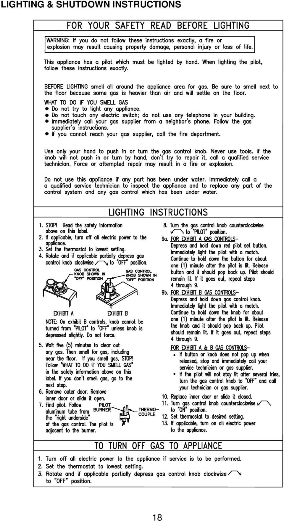
18 LIGHTING & SHUTDOWN INSTRUCTIONS 18
19 THERMOSTAT ADJUSTMENT 160 F Control 180 F Control Figure 2 The thermostat dial is set to its lowest temperature setting when shipped from the factory. Remember that lower temperature settings are more energy efficient. Adjust the temperature by turning the thermostat dial. It is suggested that the starting point setting not be greater than the or mark on the thermostat dial (approximately 120 F [48.9 C]) V as indicated below. Rotate the thermostat dial clockwise to decrease the temperature setting. Rotate the thermostat dial counter-clockwise to increase the temperature setting. Adjust the dial until the minimum acceptable temperature is achieved (See figure 2 above for approximate temperature settings). 160 F Control 180 F Control Figure 3 The thermostat dial is set to its lowest temperature setting when shipped from the factory. Remember that lower temperature settings are more energy efficient. Adjust the temperature by turning the thermostat dial. It is suggested that the starting point setting not be greater than the mark on the thermostat dial (approximately 120 F [48.9 C]) as indicated below. Rotate the thermostat dial counter-clockwise to decrease the temperature setting. Rotate the thermostat dial clockwise to increase the temperature setting. Adjust the dial until the minimum acceptable temperature is achieved (See figure 3 above for approximate temperature settings). 19
![It is suggested that the starting point setting not be greater than the or mark on the thermostat dial (approximately 120 F [48.9 C]) V as indicated below.](/docs-images/47/23680871/images/page_19.jpg "Rotate the thermostat dial clockwise to decrease the temperature setting. Rotate the thermostat dial counter-clockwise to increase the temperature setting.")
20 General Operation continued- Hotter water increases the risk of scald injury. Scalding may occur within five (5) seconds at a temperature setting of 140 F (60 C). To protect against hot water injury, install an ASSE approved mixing valve in the water system. This valve will reduce point of discharge temperature by mixing cold and hot water in branch water lines. A licensed plumbing professional or local plumbing authority should be consulted. Note: This water heater is equipped with an energy cut out device to prevent overheating. Should overheating occur or the gas supply fails to shut off, turn off the manual gas control valve to the appliance and call a qualified service technician. Note: Whenever the water heater is filled with cold water, condensate will form on the cool tank surface and drops of water will fall on the hot burner and combustion chamber surfaces producing a sizzling noise. Condensation is normal and does not indicate a leak. It will disappear when the tank becomes heated. BURNER FLAME CHECKS DANGER Cast Iron Burner: At the time of installation and at periodic intervals (not more than 6 months), a visual check of the main burner and pilot flames should be made to determine if they are burning properly. For ideal operation, the gas and air must be properly proportioned. The proper air-gas mixture is obtained by adjusting the air shutter on the mixer face of the main burner (See Figure 5). To adjust for proper burning, loosen the air shutter nut, rotate shutter to close the opening in the burner then slowly rotate the shutter until the yellow tips disappear and the flame becomes blue. Tighten the air shutter nut. Too much air will cause the flame to lift off the burner ports and create noisy operation. Too little air will result in soot formation. The main burner flame should light smoothly from the pilot. Steel Burner: These models are equipped with self adjusting air mixture and do not have an adjustable air shutter (See Figure 4). At periodic intervals, a visual check of the main burner and pilot flames should be made to determine if they are burning properly. The main burner flame should light smoothly from the pilot. Figure 5 Figure 4 20

21 General Operation continued- Water heaters are heat producing appliances. To avoid damage or injury there shall be no materials stored against the water heater or vent-air intake system, and proper care shall be taken to avoid unnecessary contact (especially by children) with the water heater and vent-air intake system. UNDER NO CIRCUMSTANCES SHALL FLAMMABLE MATERIALS, SUCH AS GASOLINE OR PAINT THINNER TO BE USED OR STORED IN THE VICINITY OF THIS WATER HEATER, VENT-AIR INTAKE SYSTEM OR IN ANY LOCATION FROM WHICH FUMES COULD REACH THE WATER HEATER OR VENT-AIR INTAKE SYSTEM. MAINTENANCE The following maintenance should be performed by a qualified service technician at the minimum periodic intervals suggested below. In some installations, the maintenance interval may be more frequent depending on the amount of use and the operating conditions of the water heater. Regular inspection and maintenance of the water heater and vent-air intake system will help to insure safe and reliable operation. 1. Annually check the operation of the thermostat. 2. The flow of combustion and ventilation air MUST NOT be restricted. Clear the combustion air openings of any dirt, dust, or other restrictions.! The ventilation air system may be HOT. IMPORTANT The water heater should be inspected at a minimum annually by a qualified service technician for damaged components and/or joints not sealed. DO NOT operate this water heater if any part is found damaged or if any joint is found not sealed. 3. At all times keep the water heater area clear and free from combustible materials, gasoline and other flammable vapors and liquids. 4. Bi-annually conduct a visual check of the main and pilot burner flames to determine that they are burning properly. See Burner Flame Check section on page Annually remove the inner door and main burner assembly to clean orifices and related parts of any dirt or other foreign material. Inspect the burner ports for obstructions or debris and clean with a wire brush as needed. Wire brush and/or vacuum clean the combustion chamber as needed to remove scale deposits and debris. NOTE: It is imperative for proper operation of the water heater that the inner door be replaced in the original location. 21
22 Maintenance continued- When lifting lever of the combination temperature and pressure relief valve, hot water will be released under pressure. Be careful that any released water does not result in bodily injury or property damage. 6. At least once a year, check the combination temperature and pressure relief valve to insure that the valve has not become encrusted with lime. Lift the lever at the lever at the top of the valve several times until the valve seats properly without leaking and operates freely. 7. Monthly drain off a gallon of water to remove silt and sediment.! THIS WATER MAY BE HOT. 8. If the combination temperature and pressure relief valve on the appliance discharges periodically, this may be due to thermal expansion in a closed water supply system. Contact the water supplier or local plumbing inspector on how to correct this situation. Do not plug the combination temperature and pressure relief valve outlet. 9. A combination sacrificial anode rod/hot water outlet nipple has been installed to extend tank life. The anode rod should be inspected periodically (every 2 years) and replaced when necessary to prolong tank life. Water conditions in your area will influence the time interval for inspection and replacement of the anode rod. Contact the plumbing professional who installed the water heater or the manufacturer listed on the rating plate for anode replacement information. The use of a water softener may increase the speed of anode consumption. More frequent inspection of the anode is needed when using softened (or phosphate treated) water. CAUTION FOR YOUR SAFETY, DO NOT ATTEMPT REPAIR OF COMBINATION GAS CONTROL, BURNERS OR GAS PIPING. REFER REPAIRS TO A QUALIFIED SERVICE TECHNICIAN. Contact your supplier or plumbing professional for replacement parts or contact the company at the address given on the rating plate of the water heater. Provide the part name, model and serial numbers of the water heater when ordering parts. READ THE WARRANTY FOR A FULL EXPLANATION OF THE LENGTH OF TIME THAT PARTS AND THE WATER HEATER ARE WARRANTED. 22
23 Maintenance continued- Manufactured under one or more of the following U.S. Patents: RE.34,534; B1 5,341,770; 4,416,222; 4,628,184; 4,669,448; 4,672,919; 4,808,356; 4,829,983; 4,861,968; 4,904,428; 5,000,893; 5,023,031; 5,052,346; 5,081,696; 5,092,519; 5,115,767; 5,199,385; 5,277,171; 5,372,185; 5,485,879; 5,574,822; 5,596,952; 5,660,165; 5,682,666; 5,761,379; 5,943,984; 5,954,492; 5,988,117; 6,142,216; 6,684,821; 7,063,132; Other U.S. and Foreign patent applications pending. Current Canadian Patents: 1,272,914; 1,280,043; 1,289,832; 2,045,862; 2,092,105; 2,107,012; 2,108,186; 2,112,515 Complete the following information and retain for future reference: Model No: Serial No: Service Phone Days: Nights: Address: Supplier: Supplier Phone No: Figure 6 23
24 PARTS LIST AND DRAWING PART NAME AND DESCRIPTION 1. Draft Diverter 15. Jacket 2. Flue Core Assembly (Certain Models) 16. Combustion Chamber 3. Jacket Head Pan 17. Radiation Shield 4. Fiberglass Head Insulation 18. Combustion Chamber Door 5. Flue Baffle Assembly 19. Jacket Base Pan 6. Magnesium Anode-Hot Water Outlet 20. Heater Leg 7. Dip Tube-Cold Water Inlet 21. Thermocouple Lead 8. Temperature and Pressure Relief Valve 22. Gas Feedline to Pilot 9. Glass Lined Tank 23. Gas Feedline to Burner 10. Foam Insulation 24. Orifice 11. Thermostat with ECO 25. Air Shutter (Cast Iron Burner Only) 12. Drain Valve 26. Cast Iron Burner 13. Fiberglass Insulation 27. Pilot Assembly 14. Outer Door (Varies by Model) 28. Steel Burner (Varies by Model) 24
25 THE FOLLOWING INSTRUCTIONS ARE FOR INSTALLATION OF: GAS WATER HEATERS SUITABLE FOR WATER (POTABLE) HEATING AND SPACE HEATING CAUTION THE COIL PROVIDED IN THIS WATER HEATER IS MANUFACTURED USING AN ALUMINUM ALLOY INNER WALL, CROSS-LINKED POLY- ETHYLENE OUTER WALL AND NITRILE/HDPM O RING(S). DO NOT USE COMPONENTS OR MATERIALS WHICH MAY NOT BE COMPATIBLE WITH THESE MATERIALS. THIS MAY CAUSE PREMATURE FAILURE OF THE COIL AND/OR THE WATER HEATER. 1. All piping components connected to this water heater for space heating applications must be suitable for use with potable water. In Massachusetts, space heating piping length must not exceed 50 feet. 2. Toxic chemicals, such as those used for boiler treatment, must not be introduced into potable water used for space heating. 3. This water heater must not be connected to an existing heating system or component(s) previously used with a non-potable water heating appliance. 4. When the system requires water for space heating at temperatures higher than required for other means, such as an ASSE approved mixing valve shall be installed to temper the water for those uses in order to reduce the scald hazard potential. Please refer to the illustrations below for the suggested piping arrangement. 25
INDIRECT WATER HEATER. Installation and Operating Instruction Manual
 INDIRECT WATER HEATER Installation and Operating Instruction Manual Maximum supply temperature to heat exchanger must not exceed 180 F (82 C). Safety Warning: Indirect water heaters are heat-producing
ELECTRIC WATER HEATER INSTALLATION & OPERATING INSTRUCTION MANUAL
 ELECTRIC WATER HEATER A Spanish language version of these instructions is available by contacting the manufacturer listed on the rating plate. La version espanola de estas instruccions se puede obtener
COMMERCIAL ELECTRIC WATER HEATER INSTALLATION & OPERATING INSTRUCTION MANUAL
 COMMERCIAL ELECTRIC WATER HEATER La A version Spanish espanola language de version estas of instrucciones these instructions se puede is available obtener al by escribirle contacting a la the fábrica company
GAS-FIRED WATER HEATER
 GAS-FIRED WATER HEATER A Spanish language version of these instructions is available by contacting the company listed on the rating plate. La version espanola de estas instrucciones se puede obtener al
LIGHT DUTY COMMERCIAL ELECTRIC WATER HEATER INSTALLATION & OPERATING INSTRUCTION MANUAL
 LIGHT DUTY COMMERCIAL ELECTRIC WATER HEATER A Spanish language version of these instructions is available by contacting the company listed on the rating plate. La versión espãnola de estas instrucciones
GAS-FIRED COMMERCIAL WATER HEATER
 GAS-FIRED COMMERCIAL WATER HEATER WARNING: If the information in these instructions is not followed exactly, a fire or explosion may result causing property damage, personal injury or death. - Do not store
INSTALLATION & SERVICE MANUAL
 INSTALLATION & SERVICE MANUAL POWER VENTED GAS WATER HEATER If the information in these instructions is not followed exactly, a fire or explosion may result causing property damage, personal injury, or
INSTALLATION AND OPERATING INSTRUCTION MANUAL
 POWERED DIRECT VENT GAS WATER HEATER A Spanish language version of these instructions is available by contacting the company listed on the rating plate. La version espanola de estas instrucciones se puede
CARING FOR YOUR WATER HEATER
 http://waterheatertimer.org/troubleshoot-rheem-tankless-water-heater.html Water Heater Inspections CARING FOR YOUR WATER HEATER Venting System (Direct Vent Only) The venting system should be inspected
Your safety and the safety of others are very important.
 NATURAL GAS TO PROPANE CONVERSION KIT 090 INSTALLATION INSTRUCTIONS FOR ALTITUDES 0 -,00 FT. ONLY PROPANE CONVERSION KIT SAFETY... INSTALLATION REQUIREMENTS... Tools and Parts... LP Gas Requirements...
RESIDENTIAL GAS-FIRED WATER HEATERS OWNER S MANUAL INSTALLATION AND OPERATING INSTRUCTIONS
 RESIDENTIAL GAS-FIRED WATER HEATERS (EQUIPPED WITH FVIR TECHNOLOGY) OWNER S MANUAL INSTALLATION AND OPERATING INSTRUCTIONS This water heater IS NOT design certified for installation in a manufactured (mobile)
Instruction Manual for Residential Gas Water Heaters
 Instruction Manual for Residential Gas Water Heaters NOT FOR USE IN MANUFACTURED (MOBILE) HOMES GAMA certification applies to all residential gas water heaters with capacities of 20 to 100 gallons with
Instruction Manual for Residential Manufactured Home Gas Water Heaters
 Instruction Manual for Residential Manufactured Home Gas Water Heaters FOR USE ONLY IN MANUFACTURED HOMES GAMA certification applies to all residential gas water heaters with capacities of 20 to 100 gallons
Instantaneous gas water heater
 Instantaneous gas water heater Models W 125...T1 installation operation maintenance The Bosch instantaneous water heater is a high efficiency, space saving answer to your water heating needs. All Bosch
36G22, 36G23, 36G24 & 36G52 36J22, 36J23, 36J24 & 36J52 DSI and HSI Single Stage Combination Gas Valve
 Operator: Save these instructions for future use! FAILURE TO READ AND FOLLOW ALL INSTRUCTIONS CAREFULLY BEFORE INSTALLING OR OPERATING THIS CONTROL COULD CAUSE PERSONAL INJURY AND/OR PROPERTY DAMAGE. DESCRIPTION
Tankless Water Heater
 Tankless Water Heater USER S INFORMATION MANUAL Models WGRTNG199 / WGRTLP199 WGRTCNG199 / WGRTCLP199 NOTICE: Westinghouse reserves the right to make product changes or updates without notice and will not
INSTALLATION AND OPERATIONS GUIDE FOR GRAND CANYON GAS LOG SYSTEMS
 INSTALLATION AND OPERATIONS GUIDE FOR GRAND CANYON GAS LOG SYSTEMS Installation and service must be provided by a qualified installer, service agency or gas supplier Grand Canyon Gas Logs, logs are made
INSTALLATION, OPERATION, AND SERVICE MANUAL RESIDENTIAL STORAGE TYPE GAS WATER HEATER
 INSTALLATION, OPERATION, AND SERVICE MANUAL RESIDENTIAL STORAGE TYPE GAS WATER HEATER THESE INSTRUCTIONS ARE INTENDED AS AN AID TO QUALIFIED SERVICE PERSONNEL FOR PROPER INSTALLATION, ADJUSTMENT AND OPERATION
RESIDENTIAL GAS WATER HEATERS
 Instruction Manual RESIDENTIAL GAS WATER HEATERS NOT FOR USE IN MANUFACTURED (MOBILE) HOMES For Your Safety AN ODORANT IS ADDED TO THE GAS USED BY THIS WATER HEATER. ALL TECHNICAL AND WARRANTY QUESTIONS:
INSTALLATION & SERVICE MANUAL
 SINGLE-WALL INDIRECT WATER HEATER To avoid damage or injury, there must be no materials stored against the indirect water heater and proper care shall be taken to avoid unnecessary contact (especially
SL280UHV SERIES GAS FURNACE WARNING
 2010 Lennox Industries Inc. Dallas, Texas, USA 506677 01 11/2010 Supersedes 506409 01 SL280UHV SERIES GAS FURNACE Litho U.S.A. FIRE OR EXPLOSION HAZARD. Failure to follow safety warnings exactly could
OPERATING, INSTALLATION AND SERVICE MANUAL
 OPERATING, INSTALLATION AND SERVICE MANUAL COMMERCIAL GAS WATER HEATER WITH FLUE DAMPER AND ELECTRIC IGNITION SYSTEM WITHOUT FAN MOTOR REQUIRES 120V A.C. POWER SUPPLY WARNING: If the information in these
2010 Residential Water Heater Replacement Check List
 2010 Residential Water Heater Replacement Check List The intent of this check list is to provide installers a general reference for the enforcement of code requirements in the Greater San Diego Area. This
COMMERCIAL GAS WATER HEATER Glass-Lined Tank-Type Water Heater
 COMMERCIAL GAS WATER HEATER Glass-Lined Tank-Type Water Heater INSTALLATION OPERATION SERVICE MAINTENANCE Thank you for buying this energy efficient water heater. We appreciate your confidence in our products.
Water Heaters. Residential 30, 40 and 50 Gallon
 Residential 30, 40 and 50 Gallon Use & Care Manual With Installation Instructions for the Contractor Gas Residential Water Heaters Model: HG Series, GG Series, GP Series, PG Series, SG Series, SG Series
PURCHASED. IF YOU ARE UNSUCCESSFUL, PLEASE WRITE TO THE COMPANY LISTED ON THE RATING PLATE ON THE WATER HEATER.
 Instruction Manual RESIDENTIAL GAS WATER HEATERS FOR USE ONLY IN MANUFACTURED HOMES GAMA certification applies to all residential gas water heaters with capacities of 20 to 100 gallons with input rating
COMMERCIAL GAS-FIRED WATER HEATERS OWNER S MANUAL INSTALLATION AND OPERATING INSTRUCTIONS
 COMMERCIAL GAS-FIRED WATER HEATERS OWNER S MANUAL INSTALLATION AND OPERATING INSTRUCTIONS This water heater IS NOT design certified for installation in a manufactured (mobile) home or for installation
Residential Gas Water Heaters. Residential 30, 38, 40 and 50 Gallon
 ! Warning: This water heater is not suitable for use in manufactured (mobile) homes! Use & Care Manual With Installation Instructions for the Installer Residential Gas Water Heaters The purpose of this
PURCHASED. IF YOU ARE UNSUCCESSFUL, PLEASE WRITE TO THE COMPANY LISTED ON THE RATING PLATE ON THE WATER HEATER.
 Instruction Manual COMMERCIAL GAS WATER HEATERS MODELS CG(N,L)075075, CG(N,L)075100 Series 300, 301 300 Maddox Simpson Parkway Lebanon, TN 37090 Phone: 615-889-8900 Fax: 615-547-1000 Technical Service
RESIDENTIAL GAS WATER HEATERS
 Instruction Manual RESIDENTIAL GAS WATER HEATERS NOT FOR USE IN MANUFACTURED (MOBILE) HOMES GAMA certification applies to all residential gas water heaters with capacities of 20 to 100 gallons with input
Use & Care Manual. Electric Tankless Water Heaters. With Installation Instructions for the Installer AP15447 (10/10)
") Use & Care Manual With Installation Instructions for the Installer Electric Tankless Water Heaters The purpose of this manual is twofold: one, to provide the installer with the basic directions and recommendations
Use & Care Manual With Installation Instructions for the Installer Electric Tankless Water Heaters The purpose of this manual is twofold: one, to provide the installer with the basic directions and recommendations
Residential 30, 38, 40, 50 and 60 Gallon
 ! WARNING: This water heater is not suitable for use in manufactured (mobile) homes! Use & Care Manual With Installation Instructions for the Installer Residential Gas - FVIR Certified Water Heaters Residential
Water Heaters. Residential 30, 40 and 50 Gallon
 ! WARNING: This water heater is not suitable for use in manufactured (mobile) homes! Use & Care Manual With Installation Instructions for the Installer Gas Residential Water Heaters Model: HG Series, GG
USER S, MAINTENANCE and SERVICE INFORMATION MANUAL
 CONTENTS SAFETY INFORMATION................ 2 FOR YOUR SAFETY....................... 2 SYSTEM OPERATION.................. 2 THERMOSTATS........................... 2 INTERMITTENT IGNITION DEVICE...........
Indirect-Fired Storage Water Heater Models WH-30 through WH-80 INSTALLATION AND OPERATING INSTRUCTIONS
 Indirect-Fired Storage Water Heater Models WH-30 through WH-80 INSTALLATION AND OPERATING INSTRUCTIONS Contents Page Ratings and Specifications..................... 2 Installation Requirements......................
COMMERCIAL GAS WATER HEATERS
 Instruction Manual COMMERCIAL GAS WATER HEATERS POWER VENTED GAS MODELS W/HOT SURFACE IGNITION MODEL BTX-80 SERIES 100 500 Tennessee Waltz Parkway Ashland City, TN 37015 Low Lead Content For Your Safety
OPERATING, INSTALLATION AND SERVICE MANUAL STORAGE TYPE GAS WATER HEATER 95001 12/94
 OPERATING, INSTALLATI AND SERVICE MANUAL STORAGE TYPE GAS WATER HEATER 95001 12/94 : This information in these instructions must be followed exactly. Improper installation, adjustment, alteration, service
Gas Water Heater with the Flame Guard Safety System Installation Instructions and Use & Care Guide
 Gas Water Heater with the Flame Guard Safety System Installation Instructions and Use & Care Guide Made under license from Flame Guard Water Heaters, Inc. R WARNING: If the information in these instructions
Gas-Fired, Residential Storage Type Water Heaters
 Consulting, Resource, Education, Training, and Support Services for Home Inspectors A candle loses no light when it lights another candle. Gas-Fired, Residential Storage Type Water Heaters Most inspectors
ULTRA HIGH EFFICIENCY COMMERCIAL GAS WATER HEATER (EF Series Models)
") ULTRA HIGH EFFICIENCY COMMERCIAL GAS WATER HEATER (EF Series Models) WARNING: If the information in these instructions is not followed exactly, a fire or explosion may result causing property damage, personal
ULTRA HIGH EFFICIENCY COMMERCIAL GAS WATER HEATER (EF Series Models) WARNING: If the information in these instructions is not followed exactly, a fire or explosion may result causing property damage, personal
OWNER S MANUAL FORCE 10 MARINE COMPANY 23080 HAMILTON ROAD RICHMOND, BC CANADA V6V 1C9 TEL: (604) 522-0233 FAX: (604) 522-9608
 522-0233 FAX: (604) 522-9608") Electric Water Heater OWNER S MANUAL FORCE 10 MARINE COMPANY 23080 HAMILTON ROAD RICHMOND, BC CANADA V6V 1C9 TEL: (604) 522-0233 FAX: (604) 522-9608 If your water Heater is Damaged or you have questions
Electric Water Heater OWNER S MANUAL FORCE 10 MARINE COMPANY 23080 HAMILTON ROAD RICHMOND, BC CANADA V6V 1C9 TEL: (604) 522-0233 FAX: (604) 522-9608 If your water Heater is Damaged or you have questions
Water Heaters. Use & Care Manual. Residential Gas. With Installation Instructions for the Installer. Residential 48, 63, 75, and 98 Gallon
 ! Warning: This water heater is not suitable for use in manufactured (mobile) homes! Use & Care Manual With Installation Instructions for the Installer Residential Gas Water Heaters The purpose of this
Sun Bandit Hybrid Water Heater Installation, Operation and Solar Hybrid Energy Systems Patent(s) Pending
 Pending") Solar Hybrid Energy Systems Patent(s) Pending Sun Bandit Hybrid Water Heater Installation, Operation and Solar Hybrid Energy Systems Patent(s) Pending Maintenance Manual Solar Hybrid Energy Systems Patent(s)
Solar Hybrid Energy Systems Patent(s) Pending Sun Bandit Hybrid Water Heater Installation, Operation and Solar Hybrid Energy Systems Patent(s) Pending Maintenance Manual Solar Hybrid Energy Systems Patent(s)
USER S INFORMATION MANUAL
 USER S INFORMATION MANUAL UPFLOW, DOWNFLOW, UPFLOW/HORIZONTAL & HORIZONTAL ONLY INDUCED DRAFT GAS FURNACES Recognize this symbol as an indication of Important Safety Information If the information in this
Sun Bandit Hybrid Water Heater Installation, Operation and Solar Hybrid Energy Systems Patent(s) Pending
 Pending") Solar Hybrid Energy Systems Patent(s) Pending Sun Bandit Hybrid Water Heater Installation, Operation and Solar Hybrid Energy Systems Patent(s) Pending Maintenance Manual Solar Hybrid Energy Systems Patent(s)
Solar Hybrid Energy Systems Patent(s) Pending Sun Bandit Hybrid Water Heater Installation, Operation and Solar Hybrid Energy Systems Patent(s) Pending Maintenance Manual Solar Hybrid Energy Systems Patent(s)
INSTALLATION, OPERATION, AND SERVICE MANUAL POWER VENT STORAGE TYPE GAS WATER HEATER MODELS PVG/PVCG
 INSTALLATION, OPERATION, AND SERVICE MANUAL POWER VENT STORAGE TYPE GAS WATER HEATER MODELS PVG/PVCG THESE INSTRUCTIONS ARE INTENDED AS AN AID TO QUALIFIED SERVICE PERSONNEL FOR PROPER INSTALLATION, ADJUSTMENT
Residential Gas Water Heater with the Flame Guard Safety System Installation Instructions and Use & Care Guide
 WARNING: If the information in these instructions is not followed exactly, a fire or explosion may result causing property damage, personal injury or death. Do not store or use gasoline or other flammable
Instruction Manual. Series 300, 301. For Your Safety AN ODORANT IS ADDED TO THE GAS USED BY THIS WATER HEATER.
 500 Tennessee Waltz Parkway Ashland City, TN 37015 Instruction Manual COMMERCIAL GAS WATER HEATERS MODELS BT-80, BT-100 Series 300, 301 INSTALLATION - OPERATION - SERVICE - MAINTENANCE - LIMITED WARRANTY
American Fireglass Outdoor Fire pit kit information. General instructions/warnings for outdoor gas pan and burner systems
 American Fireglass Outdoor Fire pit kit information General instructions/warnings for outdoor gas pan and burner systems We strongly recommend that our burner products be installed by a licensed and certified
Operator: Save these instructions for future use!
 WHITE-RODGERS 36C01 Combination Gas Valves (24 Volt and 120 Volt Models) INSTALLATI INSTRUCTIS FAILURE TO READ AND FOLLOW ALL INSTRUCTIS CAREFULLY BEFORE INSTALLING OR OPERATING THIS CTROL COULD CAUSE
PURCHASED. IF YOU ARE UNSUCCESSFUL, CALL THE TECHNICAL SUPPORT PHONE NUMBER SHOWN ON THE WATER HEATER LABELING.
 Instruction Manual COMMERCIAL GAS WATER HEATERS POWER VENT/POWER DIRECT VENT GAS MODELS WITH HOT SURFACE IGNITION Ashland City, TN 37015 www.hotwater.com For Your Safety AN ODORANT IS ADDED TO THE GAS
Installation Instructions and Use & Care Guide
 Gas Water Heater with the Flame Guard Safety System Installation Instructions and Use & Care Guide Made under license from Flame Guard Water Heaters, Inc. R WARNING: If the information in these instructions
INSTALLATION INSTRUCTIONS
 INSTALLATION INSTRUCTIONS VGBQ SERIES CONVERSION KIT VIKING RANGE CORPORATION 111 Front Street Greenwood, Mississippi (MS) 38930 USA (662) 455-1200 IMPORTANT: PLEASE READ AND FOLLOW 1. Before beginning,
SHC 2.5, SHC 4 MINI-TANK ELECTRIC WATER HEATERS INSTALLATION INSTRUCTIONS FOR THE LICENSED PLUMBER SHC 2.5 SHC 4. English. English
 SHC 2.5, SHC 4 MINI-TANK ELECTRIC WATER HEATERS INSTALLATION INSTRUCTIONS FOR THE LICENSED PLUMBER The SHC series is tested and certified by WQA against NSF/ANSI 372 for lead free compliance. SHC 2.5 Table
THC 85 INDUSTRIAL / COMMERCIAL SPACE HEATER
 THC 85 INDUSTRIAL / COMMERCIAL SPACE HEATER Certified to / Certifié à CGA 2.14 M2000 Conforms to / Conforme à ANSI std Z83.7 2000 Suitable for indoor or outdoor installation / Unvented / Unattended Type
INSTALLATION, OPERATING AND SERVICE INSTRUCTIONS
 INSTALLATION, OPERATING AND SERVICE INSTRUCTIONS HEAT-FLO HOT WATER STORAGE / BOOSTER TANKS MODELS 30-ST, 40-ST, 40L-ST, 60-ST, 60L-ST, 80-ST, 115-ST, 80-ST-C, 115-ST-C FOR SINGLE TANK INSTALLATIONS For
WATER HEATERS. If your water heater tank is leaking, then your course is clear: buy a new unit. But if it isn t, your answer is less obvious.
 HOME ENERGY GUIDE TECHNIQUES TACTICS & TIPS WATER HEATERS Minnesota Department of Commerce Energy Information Center Water heating is often the second largest energy expense in the Minnesota home, and
RESIDENTIAL ELECTRIC WATER HEATER OWNER S MANUAL INSTALLATION AND OPERATING INSTRUCTIONS
 RESIDENTIAL ELECTRIC WATER HEATER OWNER S MANUAL INSTALLATION AND OPERATING INSTRUCTIONS DANGER If the information in these instructions is not followed exactly, a fire or explosion may result causing
Electric Water Heater
 Electric Water Heater Operation and Installation Manual (LIMITED WARRANTY AND TANK REPLACEMENT POLICY) The following information should be noted at time of installation and retained for future reference.
Installation Instructions and Use & Care Guide
 WARNING: If the information in these instructions is not followed exactly, a fire or explosion may result causing property damage, personal injury or death. Do not store or use gasoline or other flammable
CALIFORNIA PROPOSITION 65 WARNING:
 Residential Solar Water Heater USE & CARE MANUAL WITH INSTALLATION INSTRUCTIONS FOR THE CONTRACTOR LISTED 786H The purpose of this manual is twofold: one, for the installing contractor, to provide requirements
Commercial. Gas-Fired Water Heaters. Installation. Start-Up. Maintenance. Parts. Warranty. CG***N73 / CG***N65 Models
 Commercial Gas-Fired Water Heaters Installation Start-Up Maintenance Parts Warranty CG***N73 / CG***N65 Models A Suffix of X Denotes Model Set for Low NOx Operation This manual must only be used by a qualified
Please keep this manual for f uture reference.
 GAS WATER/AGUA Congratulations! You've just purchased a new Marey Portable tankless water heater and will soon begin to enjoy the benefits of going tankless. Take the time to thoroughly read and understand
INSTALLATION & MAINTENANCE MANUAL TURBOPOWER GAS, OIL & GAS/OIL WATER HEATER
 INSTALLATION & MAINTENANCE MANUAL TURBOPOWER GAS, OIL & GAS/OIL WATER HEATER Installation and service must be performed by a qualified service installer, service agency or the gas supplier. Oil Gas/Oil
DUAL HEAT EXCHANGER INDIRECT WATER HEATER
 DUAL HEAT EXCHANGER INDIRECT WATER HEATER A Spanish language version of these instructions is available by contacting the manufacturer listed on the rating plate. La version espanola de estas instruccions
Direct Vent Water Heaters
 ! Warning: This water heater is not suitable for use in manufactured (mobile) homes! Use & Care Manual With Installation Instructions for the Installer Residential Gas - FVIR Certified Direct Vent Water
Installation and Operating Instruction Manual
 Electric Mini Tank Water Heaters CMT-1.3 CMT-2.5 CMT-4.0 CMT-ST70 Tempering valve Optionally available Installation and Operating Instruction Manual Table of Contents Important Safety Instructions 3 General
Seaward Products OWNER S MANUAL WATER HEATERS. Serial Number:
 Seaward Products WATER HEATERS OWNER S MANUAL Serial Number: IMPORTANT SAFETY INSTRUCTIONS WARNING When using electrical appliances, basic safety precautions to reduce the risk of fire, electrical shock,
NOTE! READ INSTRUCTIONS FULLY BEFORE INSTALLING OR OPERATING.
 INSTALLATION AND OPERATION GUIDE FOR HARGROVE GAS LOGS PROPANE GAS ADEQUATE FIREPLACE VENTILATION IS REQUIRED FOR SAFETY. GAS LOGS MUST BE INSTALLED BY PERSONNEL QUALIFIED FOR INSTALLING GAS APPLIANCES.
AMX300 DirectConnect Mixing Valve Kits
 AMX300 DirectConnect Mixing Valve Kits INSTALLATION INSTRUCTIONS Tools needed (not supplied) 1. Wrench 2. Pliers Safety Definitions These safety terms identify information you must read. CAUTION Indicates
TANKLESS WATER HEATER USE AND CARE MANUAL
 WARNING: If the information in these instructions is not followed exactly, a fire or explosion may result, causing death, personal injury, or property damage. For Your Safety! Do not store or use gasoline
INSTALLATION, OPERATING, AND SERVICE INSTRUCTIONS
 INSTALLATION, OPERATING, AND SERVICE INSTRUCTIONS HEAT-FLO HOT WATER STORAGE/ BOOSTER TANKS MODELS 30-ST, 40-ST, 40L-ST, 60-ST, 60L-ST 80-ST, 115-ST, 80-ST-C, 115-ST-C Conforms to UL STD 174 and NSF/ANSI
INSTALLATION AND SERVICE MANUAL EPJ SERIES INDIRECT WATER HEATERS
 INSTALLATION AND SERVICE MANUAL EPJ SERIES INDIRECT WATER HEATERS FOR MODELS EPJ-40 AND EPJ-56 SEE REAR COVER FOR INDEX Read this instruction manual before installation, operation, or service. Failure
CROWN BOILER COMPANY BWF SERIES BOILER CATEGORY I VENT KIT INSTALLATION AND OPERATING INSTRUCTIONS
 CROWN BOILER COMPANY BWF SERIES BOILER CATEGORY I VENT KIT INSTALLATION AND OPERATING INSTRUCTIONS WARNING Improper installation, adjustment, alteration, service, or maintenance of this product can cause
www.garrisonwaterheaters.com Electric & Gas Water Heaters
 www.garrisonwaterheaters.com Electric & Gas Water Heaters Hot Water: Take it for Granted with Garrison According to the U.S. Department of Energy, the average American home uses 64 gallons of hot water
Techtanium Solar Indirect Water Heater Instruction Manual
 To the Installer: Please attach these instructions next to the water heater. To the Consumer: Please read these and all component instructions and keep for future reference. Techtanium Solar Indirect Water
Mini Tank water heater Electric undersink Water heaters GL 2.5 - GL 4 - GL 6+
 Mini Tank water heater Electric undersink Water heaters GL 2.5 - GL 4 - GL 6+ IMPORTANT SAFETY INSTRUCTIONS WARNING When using electrical appliances, safety precautions to reduce the risk of fire, electric
Water Heaters. Commercial Gas. Use & Care Manual. With Installation Instructions for the Installer. Commercial 75 Gallon
 VACATION WARM COOLER A B C VERY HOT HOTTER! Warning: This water heater is not suitable for use in manufactured (mobile) homes! Commercial Gas Use & Care Manual With Installation Instructions for the Installer
NAVIEN AMERICA INC. 17855 FITCH AVENUE
 Navien America Inc. Specification Details for the Navien models: CC-240 CC-240A For Potable Water Heating and Space Heating NAVIEN AMERICA INC. 17855 FITCH AVENUE IRVINE, CALIFORNIA, USA 92614 Toll Free:
Arapahoe County Residential Water Heater Installation and Inspection Guide
 Arapahoe County Residential Water Heater Installation and Inspection Guide The attached handout is designed to be a general permit submittal and inspection guide covering most installation instances, however
Do not store or use gasoline or other flammable vapors and liquids in the vicinity of this or any other appliance.
 Condensing Water Heater Operation Manual Model NPE-180A/ 210A/ 240A NPE-180S/ 210S/ 240S * Lead Free Keep this manual near this water heater for future reference whenever maintenance or service is required.
Section 43. Lead Paint Risk Factor NONE WATER HEATER STORAGE ELECTRIC
 WATER HEATER STORAGE ELECTRIC Lead Paint Risk Factor NONE TABLE OF CONTENTS PART 1: INSTALLATION REQUIREMENTS FOR CONVENTIONAL HOMES... 1 WATER HEATER REPAIRS... 1 1. APPLIANCE REPAIR... 1 WATER HEATER
CHAPTER 5 WATER HEATERS
 PlumbingCode06_ch05 5/29/06 8:12 AM Page 1 CHAPTER 5 WATER HEATERS Water heaters are only a small portion of a plumbing system, but they are important, and they can be dangerous. Many plumbers take water
SWIMMING POOL HEAT PUMP
 SWIMMING POOL HEAT PUMP Installation & User Manual Model HP40B HP50B HP65B Hayward Pool Products Canada, Inc. T: 1-888-238-7665 www.haywardpool.ca CONTENT I. Application 4 II. Features 4 III. Technical
INDIRECT WATER HEATER
 INDIRECT WATER HEATER INSTALLATION AND OPERATING INSTRUCTIONS Read and understand these instructions thoroughly before starting TABLE OF CONTENTS I) Introduction............................2 II) Safety.................................2
COMMERCIAL GAS WATER HEATER
 Owner s Manual COMMERCIAL GAS WATER HEATER FOR POTABLE WATER HEATING ONLY NOT SUITABLE FOR SPACE HEATING NOT FOR USE IN MOBILE HOMES MODEL NO. CAPACITY 153.338074 74 Gallon (280 Liter) 153.338004 98 Gallon
Mini Tank. Electric Mini Tank Water Heaters WM-1.0 WM-2.5 WM-4.0 WM-6.0. Installation and Operating Instruction Manual
 Mini Tank Electric Mini Tank Water Heaters WM-1.0 WM-2.5 WM-4.0 WM-6.0 Installation and Operating Instruction Manual Table of Contents Important Safety Instructions 3 General Information 3/6 Technical
ASX7-4-IOM-7 J30-08579
 INSTALLATION INSTRUCTIONS 4" COMBUSTION AIR INLET KIT TUBULAR GAS FIRED DIRECT SPARK PROPELLER UNIT HEATERS UNIT CONVERSION & CATEGORY III VENTING FOR SEPARATED COMBUSTION For 30,000 to 75,000 BTU/HR SUPPLEMENT
ULTRA HIGH EFFICIENCY COMMERCIAL GAS WATER HEATER
 ULTRA HIGH EFFICIENCY COMMERCIAL GAS WATER HEATER WARNING: If the information in these instructions is not followed exactly, a fire or explosion may result causing property damage, personal injury or death
INSTALLATION, OPERATION, AND SERVICE MANUAL HIGH EFFICIENCY GAS WATER HEATER 1-800-456-9805
 http://waterheatertimer.org/how-to-troubleshoot-gas-water-heater.html INSTALLATION, OPERATION, AND SERVICE MANUAL HIGH EFFICIENCY GAS WATER HEATER THESE INSTRUCTIONS ARE INTENDED AS AN AID TO QUALIFIED
LIGHT DUTY COMMERCIAL ELECTRIC WATER HEATER INSTALLATION & OPERATING INSTRUCTION MANUAL
 LIGHT DUTY COMMERCIAL ELECTRIC WATER HEATER A Spanish language version of these instructions is available by contacting the company listed on the rating plate. La versión espãnola de estas instrucciones
GAS SAFETY PRECAUTIONS
 GAS SAFETY PRECAUTIONS Instructions on what to do when a user smells gas can be obtained from the local gas supplier. These instructions must be posted in a prominent location where the unit is to be operated.
Electric Mini Tank Water Heaters WM-2.5 & WM-4.0
 Electric Mini Tank Water Heaters WM-2.5 & WM-4.0 Installation and Operating Instruction Manual Table of Contents Important Safety Instructions 2 Technical Data 3-4 General Information 5 Technical Description
PURCHASED. IF YOU ARE UNSUCCESSFUL, CALL THE TECHNICAL SUPPORT PHONE NUMBER SHOWN ON THE WATER HEATER LABELING.
 Instruction Manual RESIDENTIAL GAS WATER HEATERS POWER VENT/POWER DIRECT VENT GAS MODELS WITH HOT SURFACE IGNITION MODEL GDHE 50 SERIES 124/125 Complies with SCAQMD Low NOx Rule 1146.2 Ashland City, TN
OTF Oil Fired Pool Heater
 OTF Oil Fired Pool Heater Installation Operation Maintenance Manual Service Policy 722010 Congratulations on the purchase of your new pool heater. In order to maintain peak performance of your pool heater
Installation Manual DIAPHRAGM WELL TANK
 Installation Manual DIAPHRAGM WELL TANK IN-LINE SERIES: 2-5 & 7 GALLON VERTICAL SERIES: 14-20-25-32-36-52-65-86-96-119 GALLON HORIZONTAL SERIES: 7-14 & 20 GALLON NO LEAD NO LEAD: The weighted average of
Installation Manual DIAPHRAGM WELL TANK
 Installation Manual DIAPHRAGM WELL TANK Safety Instructions Installation Warranty IN-LINE SERIES: 2-5 & 7 GALLON HORIZONTAL SERIES: 7-14 & 20 GALLON VERTICAL SERIES: 14-20-32-36-52-86-96-119 GALLON KEEP
Replacement parts. WM97+ gas-fired water boiler Boiler Manual. OBTAIN PARTS ONLY THROUGH WEIL-McLAIN THE BOILER CONTAINS CERAMIC FIBER MATERIALS
 Replacement parts DO NOT SERVICE THE BOILER WITHOUT A WM97+ MAINTENANCE KIT AVAILABLE Failure to adhere to these guidelines can result in severe personal injury, death or substantial property damage. The
ULTRA HIGH EFFICIENCY COMMERCIAL GAS WATER HEATER (EF Series Models)
") ULTRA HIGH EFFICIENCY COMMERCIAL GAS WATER HEATER (EF Series Models) Ambler, PA 19002 Tech. Service (800) 334-3393 Service Parts (800) 538-2020 Warranty Service (800) 531-2111 WARNING: If the information
ULTRA HIGH EFFICIENCY COMMERCIAL GAS WATER HEATER (EF Series Models) Ambler, PA 19002 Tech. Service (800) 334-3393 Service Parts (800) 538-2020 Warranty Service (800) 531-2111 WARNING: If the information
Product and Safety Information... 2,3 Service and Maintenance Munchkin Operation Primary Water
 User Manual TABLE OF CONTENTS Product and Safety Information............................................. 2,3 Service and Maintenance Munchkin Operation Primary Water Section I Combustion Air Prevention