SMF2-FG Series Media Filter Operating & Maintenance Manual
|
|
|
- Allison Roberts
- 9 years ago
- Views:
Transcription
1
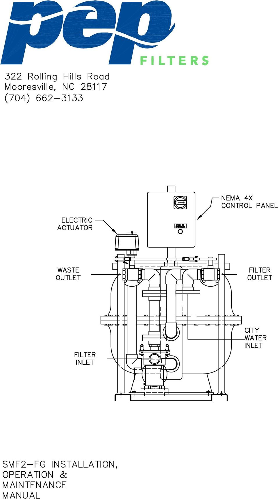
2 Process Efficiency Products filtration equipment has been designed to give long, troublefree service when properly installed, operated and maintained. This manual is a guide to establishing installation procedures and a maintenance program. IT IS IMPORTANT THAT MAINTENANCE PERSONNEL REVIEW THIS MANUAL CAREFULLY - INCLUDING THE SAFETY PRECAUTIONS AND WARNINGS LOCATED ON PAGE 11 PRIOR TO PERFORMING ANY REPAIRS OR MAINTENANCE ON THE INDUSTRIAL WATER FILTER. Included in this manual are the recommended procedures for installation, start-up, operation and shutdown for the PEP Industrial Water Filters. Note that the recommendations on frequency of service are minimums, and where operating conditions are severe, the service should be performed more often. For each required service, follow the procedures outlined under the Maintenance Procedures section of this manual. The PEP Industrial Water Filter construction details are shown on the cover with the major points of inspection and service identified. If you need further information that is not covered in this manual, please contact your local PEP Representative or the PEP factory. TABLE OF CONTENTS PAGE Filter Illustration Cover General Description 2 Filter Operation 2 Installation Rigging 2/3 Piping 3 Electric Actuator Requirement 4 Loading the Media 4 Wiring 4/5 Operation and Maintenance Initial and Seasonal Start-Up 6 After 1st Hour of Operation 7 Operation 7 Cold Weather Operation 7/8 Seasonal Shutdown 8 Maintenance Procedures Pump Pre-Strainer 8 Pump 9 Backwashing 9 Filter Tank 10 Water Treatment 10 Factory Authorized Parts 10/11 SAFETY PRECAUTIONS 11 Miscellaneous 12/15 Drawings (Outside USA) Page 1 of 16 Fax

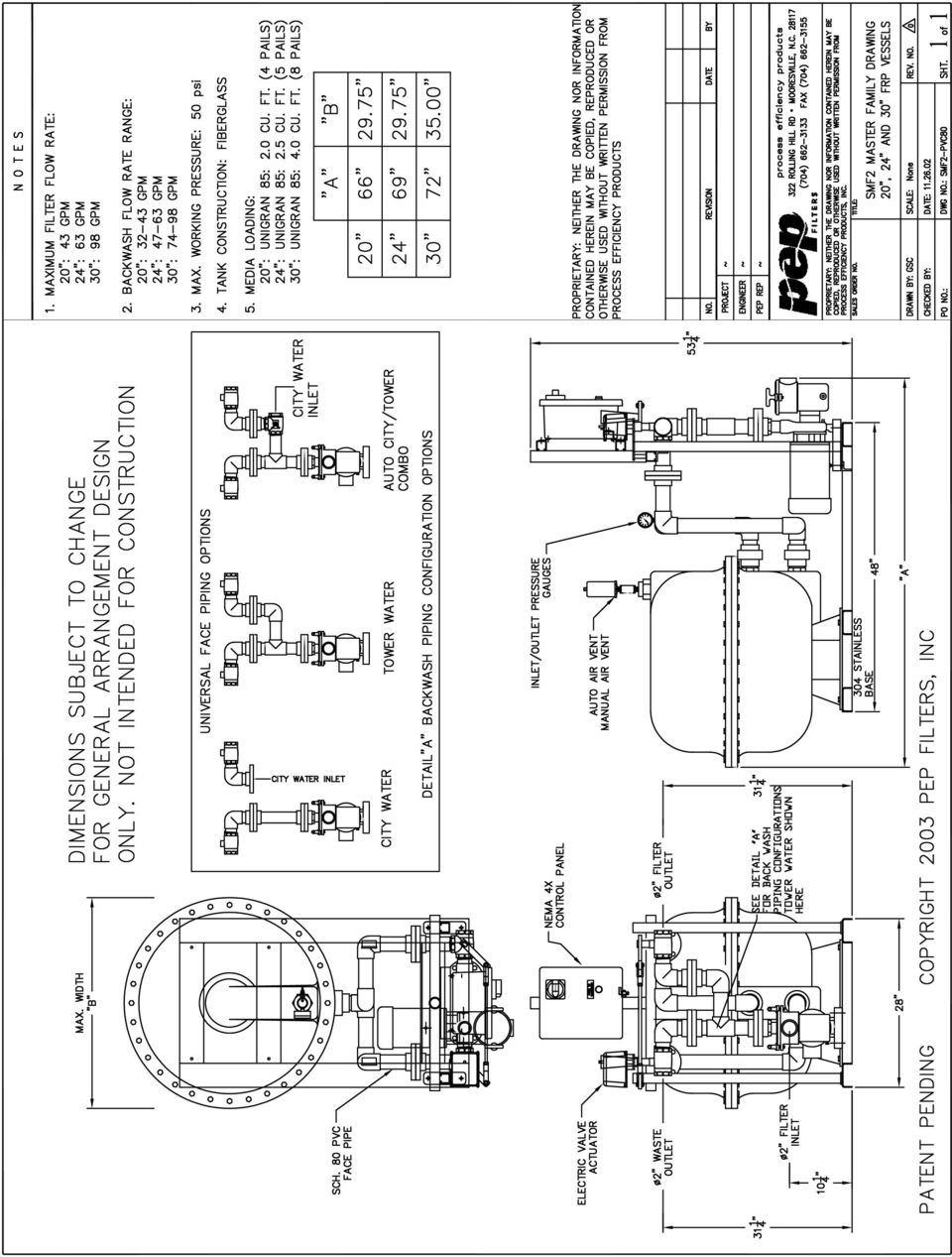
3 GENERAL DESCRIPTION The PEP SMF-FG Series Industrial Water Filters are permanent media type units specifically designed to clean industrial and process water. The PEP SMF-FG filters are designed for side-stream or in-line applications on non-pressurized systems. The SMF-FG filter vessel is constructed of fiberglass reinforced thermoplastic and has a pressure rating of 50 psig (350 kpa). FILTER OPERATION Water from the system is pumped through the over-drain assembly at the top of the filter tank and distributed evenly over the media. Suspended particles are trapped in the filter media. The filtered water then passes from the vessel through the under-drain assembly at the bottom of the filter and returns to the system. When the trapped particles cause the pressure differential across the media bed to reach a pre-determined pressure of approximately 10 PSIG (69 kpa) over starting gauge pressure, the valves are automatically or manually repositioned and the media is backwashed. The media is backwashed with a rigorous scouring action and the trapped particles are released. The dirty water passes from the filter tank through the over-drain assembly at the top of the vessel and is flushed to the drain. When the media is cleaned after a preset time (2 minutes standard), the valves are again repositioned and the filtration cycle is continued. INSTALLATION UNPACKING When the PEP Industrial Water Filter is delivered to the jobsite, it should be checked thoroughly to ensure that all required items have been received and the filter equipment is free of any shipping damage prior to signing the bill of lading. The model number of the filter will appear on a nameplate located on the unit and should be checked against the invoice/packing list. Table 1 shows the parts that should be inspected when the unit is unpacked. RIGGING 1. PEP SMF-FG units should be lifted with a forklift or overhead crane. If these units are lifted with an overhead crane, lifting straps must be located below the filter skid and should not come in contact with the filter components (Outside USA) Page 2 of 16 Fax

4 2. All PEP Industrial Water Filters should be rigidly anchored to the floor or support steel by means of anchor bolts. The SMF-FG has holes suitable for 1/2" (13mm) anchor bolts. 3. After the unit is installed at a permanent location, the pressure gauge and air relief valves should be installed on the top of the filter tank (some units will have vents already installed). The sand media should be loaded into the filter at this time. Refer to loading media section on the following page and Table 6. PIPING Piping to and from the PEP SMF-FG filter should be installed in accordance with the drawing that was specifically furnished with the unit. In the event of a conflict between subject drawing and labels on the filter piping, the drawing dictates and takes precedence over the labels. 1. Connect the feed water line from the system sump or piping to the pump inlet. If the inlet connection is located above the operating water level of the system sump, install a foot/check valve to prevent loss of suction on the pump. 2. Connect the filtered water return line from the filter outlet to the system sump or piping. 3. A service valve should be installed on the inlet, outlet, and city water line (if city water is used) to allow servicing of the filter. For units using a backwash source other than the system sump, refer to Table 3 to determine required backwash flow. Connect this line to the "City Water" connection as shown in the drawing. The maximum city water backwash supply pressure on the SMF filters should never exceed the pressure rating of the filter vessel. If public or municipal water is used for backwash, a backflow prevention or check valve is required in the line on all units (check standard local codes). 4. Connect a backwash waste line to the waste connection as shown in the drawing. This line carries the backwash wastewater to the drain. IMPORTANT: Do not put a valve in the waste line! Refer to Table 3 for the minimum and maximum backwash flow rates. Note: If the drain is not large enough to handle the volume of water during backwash, it may be necessary to use a storage tank to collect the wastewater. A valve can be used to regulate the flow from tank at a suitable rate to the drain. NEVER REDUCE THE SIZE OF WASTE WATER LINE. 5. All interconnecting piping, fittings, valves, or other accessories connected to the filter system (whether supplied by PEP or others) must be independently supported to eliminate (Outside USA) Page 3 of 16 Fax

5 stress on piping. Check with local, county, or other government authorities to ensure compliance with applicable government industry requirement codes. NOTE: The filter vessel drain plug is located on the tank bottom for 20, 24 and 30 units, and on the side near the tank bottom for 36, 42 and 48 units. ACTUATOR REQUIREMENTS PEP SMF-FG filters utilize electric actuators to control the valve action between the filtration and backwash modes. The electric actuator is designed for 110 VAC control. LOADING THE FILTER MEDIA The special spherical silica sand media used in all PEP Industrial Water Filters is designed to remove over 95% (by volume/weight) of all suspended solids. The media will ship to the jobsite in 0.5 ft 3 (14,160 cu. cm.) 50 lb./drum or in 1 ft 3 (28,320 cu. cm.) 100 lbs./bag for easy handling during the media loading process. 1. NEVER LOAD MEDIA INTO A DRY FILTER TANK, fill tank one-third to one half full with water before loading. Always check filter internals before loading media. This procedure is the same for Unigran 55 and 85. Refer to Table 6 for appropriate media quantities for a specific filter size. WIRING PEP Industrial Water Filters supplied with a pump and automatic backwash controls are provided with the following as standard: UL Type 4 control cabinet containing an on/off disconnect switch, motor overload protection, transformer to provide 110v control voltage, backwash timer, 24 hour time clock, pressure differential switch to initiate backwash, valve actuator to reposition valves for backwash, and push button for manual backwash initiation. Units are provided with the customer requested voltage/phase (460 volt, three phase standard). Check the current draw upon initial start-up and make sure that it is equal to or less than the prescribed value shown in Table 4. Units supplied with city or other source backwash are provided with a magnetic motor starter. Units supplied as manual are provided with no motor control of any kind. THE FOLLOWING RECOMMENDATIONS CONFORM TO THE 1993 NATIONAL ELECTRIC (Outside USA) Page 4 of 16 Fax
 of all suspended solids.")
6 CODE. CHECK WITH LOCAL, COUNTY, OR OTHER GOVERNMENT AUTHORITIES FOR PRESCRIBED REQUIREMENTS. NOTE: CHECK FILTER PUMP NAMEPLATE FOR HORSEPOWER AND AMP DRAW Single Phase Manual Units 1. Install a separate power supply line with circuit breaker protection between the closest branch distribution panel and the pump motor. The full load current for standard models is listed in Table Install an externally operated switch with fuse protection and door interlock in plain sight of the filter and not more than 50 feet (15m) away. The thermal overload protection, if required, must be sized for full load amp draw listed on the pump motor name plate. Three Phase Manual Units 1. Install a separate power supply line with circuit breaker protection between the closest branch distribution panel and the pump motor. The full load current for standard models is listed in Table Install a service disconnect switch in plain sight of the filter and not more than 50ft/15m away. 3. Install an externally operated manual or magnetic starter with thermal overload and fuse protection. If the unit is to be controlled remotely with a time clock, switch, or other device, a magnetic starter must be used. The thermal overload protection, if required, must be sized for the full load amp draw listed on the pump motor nameplate. Single and Three Phase Automatic Units 1. Install a separate power supply line with circuit breaker protection between the closest branch distribution panel and the control box. The full load current for standard single and three phase units is listed in Tables 4 & 5. The control box contents are pre-wired and include a service disconnect switch, thermal overload, a transformer to convert the power supply to single phase 110v for controls. Wire the power supply lines to the disconnect switch. ALL INCOMING POWER SUPPLY LINES MUST CONNECT TO DOOR INTERLOCK DISCONNECT. 24 HOUR/7-DAY TIME CLOCK The 24-hour time clock (standard, unless equipped with a PLC) is used to initiate the 2 minute backwash timer relay at any specified time in the day. The 24 hour backwash clock (Outside USA) Page 5 of 16 Fax

7 comes preset from the factory to backwash once every 24 hours of running time. For every non-consecutive pin pull-out in a 24 hour cycle the filter will backwash. Each pin represents 15 minutes of a 24-hour period. The filter can only backwash once every 1/2 hour by time clock. For every pin pulled-out consecutively, the filter will backwash once and then lock itself out for 15 minutes multiplied by the number of pins pulled out. The 7- day time clock is used to initiate the 2 minute backwash timer relay on any hour at any specific time and day of the week. As an alternate, an optional 7-day timer is preset from the factory to backwash once a week. The 7-day timer works the same as the 24-hour clock except each pin represents 2 hours. OPERATION AND MAINTENANCE INITIAL AND SEASONAL START-UP Before initial start-up or after a shut-down period, the PEP Industrial Water Filter should be thoroughly inspected and cleaned. CAUTION: Perform the first five of the following recommendations with the electric power off. Refer to the Safety Precautions regarding the safeguarding of maintenance personnel from biological contaminants, prior to Initial and Seasonal Start-Up. 1. Remove the bolts around the pump pre-strainer tank lid and remove the lid. Inspect the O-ring seal and lubricate. Remove debris from the pump pre-strainer basket. Replace the basket, lid and clamp (now is a good time to prime the pump suction line). 2. On manual systems only, rotate the valves manually by using the handle connecting the valve linkage to ensure the valves operate smoothly. Upon initial start-up, make sure the valves are in the backwash position and allow the filter to run for several minutes before re-positioning the valves to the filter mode. 3. Loosen the access bolts around the vessel circumference, remove lid and lubricate the bolts as necessary. 4. Inspect the over-drain assembly and media pack. If the media pack is contaminated, remove the foreign material or replace the media. Replace the filter vessel top. 5. Open manual air relief valve on top of the filter tank. Start the pump motor briefly and check the arrow on the pump volute for proper rotation. Turn the pump motor off. Do NOT operate the pump for an extended period of time with the pump rotating backwards. Have a qualified electrician change leads to correct rotation. 6. With the air relief valve open on top of the filter tank. Check the shut-off valves in the (Outside USA) Page 6 of 16 Fax

8 filter inlet and outlet water lines to verify they are open. Make sure the pump is primed. Start the pump and fill filter vessel. Wait for all the air in vessel to be released before closing manual air relief valve. 7. Check the voltage and current of all leads on the pump motor. The current amp draw should not exceed the nameplate rating. 8. Check the unit for any unusual noise or vibration and contact your local PEP Representative if noise or vibration occurs. 9. Check the unit for any air or water leaks. All air leaks must be found and repaired. Failure to do so could result in poor performance and/or personal injury. 10. Backwash the filter. After backwashing the filter, check the pressure gauge on top of the filter tank and record the clean media operating pressure gauge. The media should be backwashed whenever the pressure drop across the filter reaches 16 psi. AFTER FIRST HOUR OF OPERATION 1. Open the air relief valve on top of the filter tank. Close the valve after the air has been purged from the system. Excessive air release usually indicates an air leak, which must be repaired. Air accumulation in the filter tank can result in an unsafe condition due to excessive pressure within the tank. 2. Check the unit for any unusual noise or vibration and contact your local PEP Representative if noise or vibration occurs. 3. Check unit for any air or water leaks. OPERATION During operation, the PEP Industrial Filters should be inspected, cleaned and lubricated on a regular basis. The required services and recommended frequency (minimum) for each are summarized in the table Operation and Maintenance Schedule. COLD WEATHER OPERATION PEP Industrial Water Filters that will be exposed to below freezing ambient temperatures require protection to prevent freezing. Installation in a heated indoor space is the best means of preventing the water from freezing in a filter. Where indoor installation is impractical because of filter location or space limitation, supplementary heat must be supplied through the use of electrical heater tape and insulation. The parts of the filter that must be heat traced and insulated are: pre-strainer tank, pump, piping, valves, (Outside USA) Page 7 of 16 Fax

9 pressure switch tubing, and filter tank. The unit should be drained when it is to be shut down for any period of time. Refer to the Seasonal Shutdown section of the manual for recommendations. SEASONAL SHUTDOWN The following services should be performed when the unit is to be shut down for a prolonged time period. 1. Shut off all electrical power. 2. Close the shut-off valves in the filter inlet and outlet water lines. For units using a backwash source other than the system, close the shut-off valve in the line from that source also. 3. Drain all external piping to and from the filter. 4. Open the manual vent valves and open the drain line to the filter tank and piping. After the water has drained, close the drain and vent. 5. On manual units only, rotate the valves manually by moving the linkage up and down to ensure operation without obstruction. 6. Loosen the bolts around the circumference and remove the lid. Lubricate the bolt if necessary. Replace the O-ring if necessary. 7. Inspect the over-drain assembly and media pack. If the media is contaminated, remove the foreign material and replace the media if necessary. Replace the filter lid and secure the bolts. MAINTENANCE PROCEDURES PUMP PRE-STRAINER Warning: Disconnect all electrical power prior to performing pump maintenance. The filter pre-strainer basket on the pump inlet must be kept clean and free of debris. Shut off the power, close the valves, open the air relief valve, remove bolts and lid. Remove the basket and remove any foreign material. Replace basket, lubricate O-ring, and tighten clamp (Outside USA) Page 8 of 16 Fax

10 PUMP Warning: Disconnect all electrical power prior to performing pump maintenance. Turn the pump shaft by hand. The impeller should spin freely. If not, remove the pre-strainer from the volute and check with a feeler gauge. The clearance between the impeller and volute face is 0.015" (0.38 mm). Adjust the clearance, if necessary, by loosening the setscrews. The impeller and motor shaft are spring-loaded and will slide forward/back. Adjust the impeller to proper clearance and tighten set-screws. If the impeller remains obstructed, remove the 4 bolts holding the volute to the motor bracket and impeller, and inspect the volute for foreign material. Reverse the above procedures for replacement. BACKWASHING The media pack must be backwashed whenever the debris build-up causes a 16 psi pressure drop across the filter media. Since the units with automatic controls perform this function as necessary, a detailed backwash procedure is only given for manual units. However, automatic units can be manually backwashed by pushing the button on the control panel unit the valves change position. The valves will then be automatically repositioned after two minutes. The filter should be backwashed once a week minimum. For manual control units using a back wash water source other than the system: 1. Shut off the electrical power to the pump motor. 2. Move the handle on the linkage to position the valves in backwash mode. 3. Allow the filter to backwash for approximately two minutes. 4. Move the handle on the linkage to position the valves in the filtration mode. 5. Re-start the pump motor. For manual control units using the system water for backwash: 1. Shut off the electrical power to the pump motor. 2. Move the handle on the linkage to position the valves in the backwash mode. 3. Re-start the pump motor. 4. Allow the filter to backwash for approximately two minutes. 5. Shut off the electrical power to the pump motor. 6. Move the handle on the linkage to position the vales in filtration mode. 7. Re-start the pump motor (Outside USA) Page 9 of 16 Fax

11 FILTER TANK The filter tank internal components should be visually inspected annually or whenever backwashing does not reduce the pressure of the filter tank to the starting media gauge pressure. On the SMF-FG filters, remove the lid on the top of the tank to inspect the internal components. Note: Always use care and follow proper shutdown procedures. Inspect the over-drain assembly for any debris blockage or damage and clean or replace if necessary, and inspect the media. The SMF-FG filters have a 1.5" (40mm) drain plug located on the bottom of the tank for easy removal of the media and inspection of the under-drain assembly. Over a period of time, foreign matter may become imbedded in the media pack that cannot be backwashed out. Contaminated media should be discarded. Check the under-drain laterals and inspect for blockage or damage. Clean or replace if necessary. Refill tank with the proper amount of uncontaminated media, following media loading instructions (Table 6). WATER TREATMENT Filtration is an effective way of reducing the level of contamination in a system but is only one component of a water treatment program. Dissolved solids originally present in water remaining after evaporation cannot be eliminated by filtration. The concentration of these dissolved solids increases rapidly and can cause scale and corrosion. In addition, airborne impurities and biological contaminants including Legionella may be introduced into the recirculating water through the air and make-up water. To control potential contaminants a water treatment program must be employed. In many cases a simple bleed-off in the system may be adequate for control of scale and corrosion. The filter backwash can be used to constitute a portion of the bleed. However, biological contamination can be controlled through the use of biocides and such treatment should be initiated at system start-up and continued regularly thereafter. For specific recommendations on water treatment contact a competent water treatment supplier. FACTORY AUTHORIZED PARTS PEP maintains a stock of replacement parts. Shipment of parts is normally within three days after receipt of an order (provided the item is in stock). In emergency situations, shipment can usually be made within 24 hours (if stock). Be sure to include the unit serial number and model when ordering parts. To facilitate servicing the unit, it is suggested that the following parts be carried on hand: (Outside USA) Page 10 of 16 Fax
 drain plug located on the bottom of the tank for easy removal of the media and inspection of the under-drain assembly.")
12 1. O-ring or gasket for filter tank access port, hand hole and manhole gaskets. 2. O-ring seal or gasket for pump pre-strainer lid (if applicable). 3. Seal kit for pump 4. Transformer fuse (automatic units only). SAFETY PRECAUTIONS All electrical, mechanical and rotating machinery constitute a potential hazard, particularly for those not familiar with its design, construction, and operation. Accordingly, adequate safeguards (including use of protective enclosures when necessary) should be taken with this equipment both the safeguard the public (including minors) from injury and to prevent damage to the equipment, its' associate system and the premises Equipment operation, maintenance and repair should be undertaken by qualified personnel. All such personnel should be thoroughly familiar with the equipment, the associated system and controls, and the procedures set forth in this manual. Proper care, procedures, and tools must be used in handling, lifting, installing, operating, maintaining, and repairing this equipment, to prevent personal injury and/or property damage. For the protection of authorized service and maintenance personnel, the pump motor associated with this equipment should be installed with a lockable disconnect switch located in close proximity and within sight if the Industrial Water Filter. No service work should be performed on or near the pump motors, without first ensuring that the pump motor has been electrically disconnected and locked out. The re-circulating water system may contain chemicals or biological contaminants that could be harmful if inhaled or ingested. Accordingly, personnel who may be exposed directly to the mists produced by water jets or compressed air (should these be used to clean portions or components of the Industrial Water Filter) should wear half-face respirators with HEPA filter cartridges, NIOSH/MSHA approved number TC-21C-142/TC- 21C (Outside USA) Page 11 of 16 Fax
 should be taken with this equipment both the safeguard the public (including minors) from injury and to")
13 OPERATION AND MAINTENANCE SCHEDULE TYPE OF SERVICE START UP MONTHLY SEMI- ANNUALLY SHUTDOWN ANNUALLY Inspect general condition of unit Check & lubricate clamp on strainer lid Clean basket in pre-strainer tank Inspect O-ring gasket (SMF) Check pump shaft for free rotation Check operation of valves Check, lubricate filter tank access port Inspect over-drain assembly & media pack Check pump motor for proper rotation Check motor voltage & current Prime pump Check pressure gauge reading (top of filter); must be <50 psig Check unit for unusual noise or vibration Check unit for leaks Drain filter & piping (Outside USA) Page 12 of 16 Fax
; must be <50 psig Check unit for unusual noise or vibration Check unit for leaks Drain filter & piping 704-662-3133 (Outside USA) Page 12 of 16 Fax")
14 Table 1: Inspection Chart Part Filter Tank Valves & Linkage Filter Inter-connecting Piping Pump pre-strainer tank & basket Pump SMF-FG Model NEMA 4 Box (Automatic only) Filter skid Pressure gauge, air relief valves, & tees Media (ship loose) Table 2: Connection Sizes Filter Model System Water Backwash City Water Backwash Pump Inlet Filter Outlet Waste Outlet Inlet City Water SMF2-FG in / mm in / mm in / mm in / mm 20 2 / 50 2 / 50 2 / 50 2 / / 50 2 / 50 2 / 50 2 / / 50 2 / 50 2 / 50 2 / / / / / / / / / / / / / (Outside USA) Page 13 of 16 Fax
 Page 13 of 16 Fax 704-662-3155")
15 Table 3: Filter Flow 20 gpm/ft 2 (13.58 lps/m 2 ) Filter Model SMF2- FG Forward Flow Minimum Backwash Flow Maximum Backwash Flow GPM / LPS GPM / LPS GPM / LPS / / 2 43 / / / 3 63 / / / / / / / / / / / / / 15.2 Table 4: Electrical Requirements - Single Phase PUMP HP / KW Voltage 1 φ 60HZ / 50HZ Full Load Current (Amps) 0.5 / , 208, , 5.0, / , 208, , 8.8, 8 1 / , 208, , 8.8, 8 2 / , 208, , 13.2, (Outside USA) Page 14 of 16 Fax
 0.5 / 0.38 110, 208, 220 9.8, 5.0, 4.9 1 / 0.")
16 Table 5a. Electrical Requirements / Three Phase (60 Hz) PUMP Motor HP / KW Voltage 3φ 60 HZ Full Load Current (Amps) 1 / , 230, 460, 575 4, 3.6, 1.8, / , 230, 460, , 6.8, 3.4, / , 230, 460, , 9.6, 4.8, / , 230, 460, , 15.2, 7.6, 6.1 Table 5b: Electrical Requirements / Three Phase (50Hz) HP / KW Voltage 3φ 50 HZ Full Load Current (Amps) 1 / , , / , , / , , 4.7 Table 6. Media Quantities: SMF-FG Model SMF2-FG Unigran 55 & 85 (50 lb. pails) Unigran 475 (for under-drain support, 50 lb. bags) (Outside USA) Page 15 of 16 Fax
 Unigran 475 (for under-drain support, 50 lb.")
17
18

HMF2 Series Filter System Operating & Maintenance Manual
 Process Efficiency Products (PEP) filtration equipment has been designed to give long, trouble-free service when properly installed, operated and maintained. This manual includes installation and start-up
Oil and Coolant Circulating Heating System. Model - OCSM
 Oil and Coolant Circulating Heating System Model - OCSM Installation & Operation Manual 216280-000 REV 2 Identifying Your System The HOTSTART heating system is designed to heat fluids for use in marine
CARING FOR YOUR WATER HEATER
 http://waterheatertimer.org/troubleshoot-rheem-tankless-water-heater.html Water Heater Inspections CARING FOR YOUR WATER HEATER Venting System (Direct Vent Only) The venting system should be inspected
Pump Specifications 250 Series Submersible Sump / Effluent Pump 2 Solids handling
 Pump Specifications 250 Series Submersible Sump / Effluent Pump 2 Solids handling 250_P1 R10/7/2015 Copyright 2015 Liberty Pumps Inc. All rights reserved. Specifications subject to change without notice.
300 Series PA Pump and Cooler Assemblies
 Type 300 Series PA Sizes 300 thru 370 (Page 1 of 9) 300 Series PA Pump and Cooler Assemblies Pump and Cooler Assemblies with Air/Oil Heat Exchanger When compact gear drives require assistance to dissipate
ARCO Electric Products Installation and Maintenance Manual Low Voltage Automatic Power Factor Correction Capacitor Systems 2013
 ARCO Electric Products Installation and Maintenance Manual Low Voltage Automatic Power Factor Correction Capacitor Systems 2013 READ CAREFULLY These instructions are intended to cover good practices in
REFRIGERATED TYPE COMPRESSED AIR DRYERS INSTRUCTION MANUAL. For Sales & Service please contact:
 7610.478.16 8/99 INSTRUCTION MANUAL Models 8005, 8010, 8015 For Sales & Service please contact: CENTRAIR Air Systems & Supplies Phone: 705-722-5747 Fax: 705-722-5458 Email: [email protected] Website: www.centrair.ca
Rexroth Hydraulic Pump A10VO Series User Manual
 Rexroth Hydraulic Pump A10VO Series User Manual Rexroth Hydraulic pump A10VO Series User Manual Revised 5/1/2009 Page 1 of 12 Functional Purpose This pump is preferred over a fixed displacement (gear)
A Guide to Trouble-Free Cooling Towers
 A Guide to Trouble-Free Cooling Towers A basic understanding of cooling tower operation and maintenance will help keep a cooling water system running in top condition, year after year By David M. Suptic
Wilo SP Series Submersible Sump Pumps ECS. ECS19-15.25 ECS22-15.33 ECS24-15.50 Installation and operating instructions
 Wilo SP Series Submersible Sump Pumps ECS ECS19-15.25 ECS22-15.33 ECS24-15.50 Installation and operating instructions PREINSTALLATION CHECK Inspect this pump before it is used. Occasionally, pumps can
AWWA Butterfly Valve Operation and Maintenance Manual Series 511A & 510A 20 and Smaller
 January 2013 AWWA Butterfly Valve Operation and Maintenance Manual Series 511A & 510A 20 and Smaller Milliken Valve Company 190 Brodhead Avenue, Suite 100 Bethlehem, PA 18017 Phone: (610) 861-8803 Fax:
12V Portable Diaphragm Compressor Operating and Maintenance Instructions
 12V Portable Diaphragm Compressor Operating and Maintenance Instructions (Part No. DC2) Part No. Serial Number Date Purchased Table of Contents Page Safety Messages...2 Guidelines for Product Use...2 Operation
ClearView 100. Instruction Manual
 ClearView 100 Instruction Manual Important Safeguards This appliance is not intended for use by children or infirm persons without supervision. Young children should be supervised to ensure that they do
1/3 HP Submersible Sump Pump with Vertical Float Switch
 1/3 HP Submersible Sump with Vertical Float Switch Item 68476 Specifications Float Switch Operation Height 7.1 IN. ON / 2.8 IN. OFF Electrical Requirements 120V~ / 60Hz / 7.6A Power Length Maximum Capacity
CTV-1500 Cooling Tower Vacuum Operating & Maintenance Manual
 CTV-1500 Cooling Tower Vacuum Operating & Maintenance Manual Goodway Technologies Corporation 420 West Avenue Stamford, CT 06902-6384 (203)359-4708 Sales: 1-800-333-7467 Customer Service: 1-800-370-2855
OPL BASIC. Dosing System for Professional Laundry machines. Contents
 OPL BASIC Dosing System for Professional Laundry machines Contents 1 Getting Started. Page 2 2 Installation. Page 4 3 Set Up & Operation. Page 8 4 Maintenance & Accessories. Page 10 5 Troubleshooting Page
100 Series Maxi Internal Filters. Instruction Manual
 100 Series Maxi Internal Filters Instruction Manual Important Safeguards This appliance is not intended for use by children or infirm persons without supervision. Young children should be supervised to
INDIRECT WATER HEATER. Installation and Operating Instruction Manual
 INDIRECT WATER HEATER Installation and Operating Instruction Manual Maximum supply temperature to heat exchanger must not exceed 180 F (82 C). Safety Warning: Indirect water heaters are heat-producing
Service manual. Website: www.andico.com.au CAUTION - BEFORE SERVICING THE UNIT, READ THE SAFETY - PRECAUTIONS IN THIS MANUAL.
 Website: www.andico.com.au Service manual CAUTION - BEFORE SERVICING THE UNIT, READ THE SAFETY - PRECAUTIONS IN THIS MANUAL. - ONLY FOR AUTHORISED SERVICE PERSONNEL. MODELS: MPK1-09CR-QB8 MPK1-12ER-QB6
CDS TROUBLESHOOTING SECTION I. VACUUM. 1.0. Weak vacuum at wand. Gauge reads normal (10hg to 14hg)
") CDS TROUBLESHOOTING SECTION I. VACUUM 1.0. Weak vacuum at wand. Gauge reads normal (10hg to 14hg) 1.1. Clogged hoses or wand tube. Disconnect hoses and carefully check for an obstruction. 1.2. Excessive
CDS TROUBLESHOOTING SECTION I. VACUUM 1.0. Weak vacuum at wand. Gauge reads normal (10hg to 14hg) 1.1. Clogged hoses or wand tube. Disconnect hoses and carefully check for an obstruction. 1.2. Excessive
BOWIE PUMPS OPERATION - MAINTENANCE
 BOWIE PUMPS OPERATION - MAINTENANCE PUMPING PRINCIPLE: The meshing owieeof the gears cause a slight depression, with the resulting enmeshing of the gears causing a vacuum drawing the fluid being pumped
PC1131 Electric Air Compressor
 Senco Products Inc. 8485 Broadwell Road Cincinnati, Ohio 45244 PC1131 Electric Air Compressor Operating Instructions 2006 by Senco Products, Inc. Warnings for the safe use of this tool are included in
A.Y. McDonald Mfg. Co. Troubleshooting Submersible and Jet Pumps
 A.Y. McDonald Mfg. Co. Troubleshooting Submersible and Jet Pumps Troubleshooting Submersible Pumps Fuse overload or circuit breaker trips when motor is started 1. Incorrect line voltage. Check the line
Float and Thermostatic Traps Series H, C and X
 Hoffman Specialty Installation & Maintenance Instructions HS-(E) and Thermostatic Traps Series H, C and X Series C & NPT Series C NPT Series X NPT Series C NPT Series H Ratings Maximum Max. Operating NPT
MODEL 300505 INSTALLATION INSTRUCTIONS
 WWW.BURCAM.COM 2190 Boul. Dagenais West TEL: 514.337.4415 LAVAL (QUEBEC) FAX: 514.337.4029 CANADA H7L 5X9 [email protected] Your pump has been carefully packaged at the factory to prevent damage during shipping.
INSTALLATION & OPERATING INSTRUCTIONS
 INSTALLATION & OPERATING INSTRUCTIONS WARNING RISK OF ELECTRIC SHOCK. CONNECT ONLY TO A CIRCUIT PROTECTED BY A GROUND-FAULT CIRCUIT-INTERRUPTER. THE UNIT SHOULD BE INSTALLED BY A QUALIFIED SERVICE REPRESENTATIVE.
FLUSHOMETER - TANK SYSTEM
 Owner s Service Manual 501-A Series FLUSHOMETER - TANK SYSTEM 501-A Series FLUSHMATE 501-A SERIES (D) (E) (C) 2 3 (B) 1 4 (F) (A) 6 5 List of Components for 501-A Series*: 1. Lower Supply Group w/hose
INSTALLATION AND MAINTENANCE INSTRUCTIONS FOR THREE PHASE INDUCTION MOTORS
 INSTALLATION AND MAINTENANCE INSTRUCTIONS FOR THREE PHASE INDUCTION MOTORS Frames 143T - 449TZ 5100 North IH 35 Round Rock, Texas 78681 Phone: 800-451-8798 512-255-4141 Fax: 512-244-5512 RECEIVING 1. Check
Pump Specifications 405 Series Commercial Drain Pump (High-Temp) 2 Solids handling
 2 Solids handling") Pump Specifications 405 Series Commercial Drain Pump (High-Temp) 2 Solids handling 405_P1 R1/27/2012 Copyright 2012 Liberty Pumps Inc. All rights reserved. Specifications subject to change without notice.
Pump Specifications 405 Series Commercial Drain Pump (High-Temp) 2 Solids handling 405_P1 R1/27/2012 Copyright 2012 Liberty Pumps Inc. All rights reserved. Specifications subject to change without notice.
123 Industrial Loop Road Paynesville, MN 56362 Phone: 1-800-864-1649 www.master-mfg.com MASTER MANUFACTURING MASTER GARDNER
 123 Industrial Loop Road Paynesville, MN 56362 Phone: 1-800-864-1649 www.master-mfg.com MASTER MANUFACTURING MASTER GARDNER Part Number PCD E3 009B MM Rev 1 Nov. 2010 INTRODUCTION The purpose of this manual
PROAIR Water-Cooled Air Conditioner. CR43WC Model INSTRUCTION MANUAL. Rev. E 2013 Pentair Technical Products P/N 10-1008-167
 PROAIR Water-Cooled Air Conditioner CR43WC Model INSTRUCTION MANUAL Rev. E 2013 Pentair Technical Products P/N 10-1008-167 87976466 TABLE OF CONTENTS HANDLING & TESTING THE AIR CONDITIONER...3 INSTALLATION
Recommended Product Specifications Fuel Day Tank System Tramont UTRS Fuel Day Tank
 Recommended Product Specifications Fuel Day Tank System Tramont UTRS Fuel Day Tank This specification describes requirements for a Diesel Fuel Day Tank System consisting of one or more fuel tanks, an Electronic
COMPRESSED AIR DRYER
 COMPRESSED AIR DRYER Model 40211 ASSEMBLY and OPERATING INSTRUCTIONS 3491 Mission Oaks Blvd., Camarillo, CA 93011 Visit our Web site at http://www.harborfreight.com Copyright 2002 by Harbor Freight Tools.
OWNER S MANUAL FORCE 10 MARINE COMPANY 23080 HAMILTON ROAD RICHMOND, BC CANADA V6V 1C9 TEL: (604) 522-0233 FAX: (604) 522-9608
 522-0233 FAX: (604) 522-9608") Electric Water Heater OWNER S MANUAL FORCE 10 MARINE COMPANY 23080 HAMILTON ROAD RICHMOND, BC CANADA V6V 1C9 TEL: (604) 522-0233 FAX: (604) 522-9608 If your water Heater is Damaged or you have questions
Electric Water Heater OWNER S MANUAL FORCE 10 MARINE COMPANY 23080 HAMILTON ROAD RICHMOND, BC CANADA V6V 1C9 TEL: (604) 522-0233 FAX: (604) 522-9608 If your water Heater is Damaged or you have questions
Installation & Operation
 System (Roof) Air Exhaust 1 1/2" Steel 90 Degree Elbows (Provided By Plumber) 1 1/2" Steel Vent To Outside Of Building (Provided By Plumber) 3/4" x 4' Flex PVC Drain Line Floor Level P-Trap OR Floor Drain
UHIR Series. Horizontal or Vertical Mounting Industrial / Commercial Electric Unit Heater. Owner s Manual
 UHIR Series Horizontal or Vertical Mounting Industrial / Commercial Electric Unit Heater Owner s Manual This manual covers installation, maintenance and repair parts. Read carefully before attempting to
PC1130 Electric Air Compressor
 Senco Products Inc. 8485 Broadwell Road Cincinnati, Ohio 45244 PC1130 Electric Air Compressor Operating Instructions 2006 by Senco Products, Inc. Warnings for the safe use of this tool are included in
SunMaxx Solar Filling Station Operating Instructions
 SunMaxx Solar Filling Operating Instructions Content 1. Declaration of conformity... 2 2. Introduction... 2 3. Transportation and unpacking... 4 4. Mounting and commissioning... 5 5. End of operation...
Rules for Safe Operation
 Rules for Safe Operation Important: Do not attempt to operate the CleanStation until you have read and understand all of the instructions in this manual. Failure to do so may result in injury. The machine
36G22, 36G23, 36G24 & 36G52 36J22, 36J23, 36J24 & 36J52 DSI and HSI Single Stage Combination Gas Valve
 Operator: Save these instructions for future use! FAILURE TO READ AND FOLLOW ALL INSTRUCTIONS CAREFULLY BEFORE INSTALLING OR OPERATING THIS CONTROL COULD CAUSE PERSONAL INJURY AND/OR PROPERTY DAMAGE. DESCRIPTION
INTRODUCTION WARNING S!!! VOC SHOULD BE BETWEEN 78 95. MUST NOT EXCEED 96 VOC USE DC CIRCUIT BREAKER/ISOLATOR BETWEEN SOLAR PANELS & CONTROLLER
 INTRODUCTION Thank you for purchasing a WATERBOY pumping system. We set the standard for quality and economy in solar pumping. The WATERBOY range incorporates the best solar pump technologies that were
USER S MANUAL HSC-24A
 AIRREX AIR CONDITIONER USER S MANUAL HSC-24A Thank you for purchasing an AIRREX AIR CONDITIONER. BEFORE operation please read this user s manual carefully. Keep this manual readily available. It is ESSENTIAL
BUILT-IN DISHWASHER INSTALLATION INSTRUCTIONS
 BUILT-IN DISHWASHER INSTALLATION INSTRUCTIONS PLEASE READ COMPLETE INSTRUCTIONS BEFORE YOU BEGIN LEAVE INSTALLATION INSTRUCTIONS AND USER'S GUIDE WITH OWNER ALL ELECTRIC WIRING AND PLUMBING MUST BE DONE
TABLE OF CONTENTS. SECTION 1 General Information: Pg 2 Description of Operation
 GTRDD SERIES HEATLESS DRYER INSTALLATION, OPERATION & MAINTENANCE MANUAL TABLE OF CONTENTS SECTION 1 General Information: Pg 2 Description of Operation SECTION 2 Safety Instructions: Pg 3 Installation
BERMAD Fire Protection
 400E-2M/700E-2M IOM Bermad Electrically Controlled Deluge Valve with EasyLock Manual Reset Model: 400E-2M/700E-2M INSTALLATION OPERATION MAINTENANCE Application Engineering BERMAD 400E-2M/700E-2M Bermad
MBA-MM-1040/10/13/1665 MULTI MEDIA FILTERS
 MASTER Water Conditioning Corp. www.masterwater.com Installation and Operation Manual MBA-MM-1040/10/13/1665 MULTI MEDIA FILTERS with the 263/742 Logix Control Valve June 2010 Table of Contents Page No.
Trash Pumps Models: 56200, 562000, 56201, 562001, 56300, 563000, 56301, 563001
 Trash Pumps Models: 56200, 562000, 56201, 562001, 56300, 563000, 56301, 563001 Specifically designed pumps for heavy duty applications Handles solids with eas and simple to open and clean Standard roll
CLEAN AND CLEAR PLUS CARTRIDGE FILTER
 CLEAN AND CLEAR PLUS CARTRIDGE FILTER INSTALLATION AND USER S GUIDE IMPORTANT SAFETY INSTRUCTIONS READ AND FOLLOW ALL INSTRUCTIONS SAVE THESE INSTRUCTIONS i CUSTOMER SERVICE / TECHNICAL SUPPORT If you
Line to Refrigerator Ice/Water Dispenser
 Standard 18 Line to Refrigerator Ice/Water Dispenser Pump Module Bottled Water How The System Works The FLOJET Bottled Water Dispensing System was designed to pump water from a commercially available 5-gallon
Frequently Asked Questions Generators
 Frequently Asked Questions Generators Fuel Related How much fuel do the generators use during normal operation? At exercise? The generator fuel consumption is given in each of the product knowledge books
ELECTRIC/DIESEL FIRE PUMP CHECK LIST
 BUILDING NAME: DESIGNER: SCO REPRESENTATIVE: PUMP MANUF.: LOCATION: INSTALLER: DATE: OWNER NAME: INSTALLATION Certificate for flushing and hydrostatic test furnished Piping been hydrostatically tested
OPERATING AND MAINTENANCE MANUAL FOR COMMERCIAL ELECTRIC WATER HEATER ELECTRIC HEATER COMPANY BASE MODEL SE
 OPERATING AND MAINTENANCE MANUAL FOR COMMERCIAL ELECTRIC WATER HEATER ELECTRIC HEATER COMPANY BASE MODEL SE HUBBELL ELECTRIC HEATER COMPANY P.O. BOX 288 STRATFORD, CT 06615 PHONE: (203) 378-2659 FAX: (203)
Not required for most applications Not required for most applications High pressure (12-803 provided) High pressure (12-803 provided)
 High pressure (12-803 provided)") ELECTRIC FUEL PUMPS P/N 12-801-1, 712-801-1, 12-802-1, 712-802-1, 12-815-1, & 712-815-1 FUEL PRESSURE REGULATORS P/N 12-803, 12-501, 12-804, 12-500, & 15812NOS Installation Instructions THESE INSTRUCTIONS
ELECTRIC FUEL PUMPS P/N 12-801-1, 712-801-1, 12-802-1, 712-802-1, 12-815-1, & 712-815-1 FUEL PRESSURE REGULATORS P/N 12-803, 12-501, 12-804, 12-500, & 15812NOS Installation Instructions THESE INSTRUCTIONS
INSTRUCTION MANUAL A-00-091-376 REVISION A. Series E1 and E3 Instant Hot Water Recirculating Systems
 INSTRUCTION MANUAL A-00-091-376 REVISION A Series E1 and E3 Instant Hot Water Recirculating Systems HOT WATER HEATER HOT WATER HEATER BS Models A. Return into Cold Water Line at Top of Water Heater fig.
WARNING WARNING TABLE 1.
 Clean & Clear Cartridge Filter Owners Manual IMPORTANT SAFETY INSTRUCTIONS READ AND FOLLOW ALL INSTRUCTIONS SAVE THESE INSTRUCTIONS Table of Contents SECTION I. FILTER INSTALLATION... 1 SECTION II. FILTER
Hydraulic Trouble Shooting
 Hydraulic Trouble Shooting Hydraulic systems can be very simple, such as a hand pump pumping up a small hydraulic jack, or very complex, with several pumps, complex valving, accumulators, and many cylinders
Voltmaster Trash Pumps Model TSP2, TSP3 and TSP4
 Model TSP2, TSP3 and TSP4 Owner s Manual July 2010 Table of Contents 1 Introduction...................................................... 1 1.1 Read before using..............................................
JANUS INTERNATIONAL CORPORATION INSTALLATION INSTRUCTIONS Pantheon Mini Operator
 JANUS INTERNATIONAL CORPORATION INSTALLATION INSTRUCTIONS Pantheon Mini Operator The Janus Pantheon mini operator does not typically require the provision of any additional site requirements other than
WALLACE MAXIPUMP 3000, 5000, 6000 and HYDROJET 30P, 30C AND HJ400 INSTALLATION AND MAINTENANCE INSTRUCTIONS
 1 WALLACE MAXIPUMP 3000, 5000, 6000 and HYDROJET 30P, 30C AND HJ400 INSTALLATION AND MAINTENANCE INSTRUCTIONS Please read and follow all these instructions carefully before proceeding with the installation,
26 3213.13 Diesel Engine Driven Generators Page 1 of 6
 Last Update: December 8, 2014 A. Description of System Consultant s Handbook Page 1 of 6 1. Provide a diesel engine driven electric generating unit, factory assembled, tested and certified to operate at
2" & 3" Poly Wet Seal Pump Instruction Manual
 Always place the pump as close to the liquid to be pumped as possible. Keep the suction line short and with few bends. Keep the pump and engine on a level foundation. A poor foundation and a heavy suction
Electric Panel Pump Control System. Operation, Maintenance and Installation Manual
 Manual No. 5EP-OM1-1 Electric Panel Pump Control System Operation, Maintenance and Installation Manual INTRODUCTION... 1 RECEIVING AND STORAGE... 1 DESCRIPTION OF OPERATION... 1 INSTALLATION... 2 SEQUENCE
Fire Pump Plan Review March 2010
 Fire Pump Plan Review March 2010 Date of Review: / / Permit Number: Business/Building Name: Address of Project: Designer Name: Designer s Phone: Contractor: Contractor s Phone: Occupancy Classification:
Technical Guide 08/15/14
 Technical Guide 08/15/14 1 Table of Contents Contact information.3 Identifying your system..4-8 Model Number Serial number location Parts of your fuel system..9-14 Fuel pump diagram Wire harness schematics
Installation Manual. Rental Services. Air Handling Units CHS-SVN01A-EN. July 2008
 Installation Manual Rental Services Air Handling Units July 2008 CHS-SVN01A-EN Copyright 2008 Trane All rights reserved This document and the information in it are the property of Trane and may not be
Geyser-R Heat pump water heater Installation manual
 Geyser-R Heat pump water heater Installation manual 1 Version 2.9 SAFETY INFORMATION Please read carefully to prevent serious accidents or injury. The Geyser-R Heat Pump Water Heater must be installed
Water Tec of Tucson Water Systems
 Water Tec of Tucson Water Systems Water Filter Owner s Manual Water Tec of Tucson www.water-tec.com 4601 S. 3 RD Avenue Tucson, AZ 85714 (520) 790-1512 Fax (520) 745-0549 1 MAIN COMPONENTS Your water treatment
NITROUS TRANSFER PUMP INSTRUCTIONS
 NITROUS TRANSFER PUMP INSTRUCTIONS SAFETY TIPS Never directly inhale nitrous oxide. When inhaled in large quantities, nitrous oxide can cause respiratory ailments or in extreme cases, death by suffocation.
IMPORTANT SAFETY RULES TO FOLLOW
 WARNING FLOOR & CARPET CLEANER Any piece of equipment can be dangerous if not operated properly. YOU are responsible for the safe operation of this equipment. The operator must carefully read and follow
Indirect-Fired Storage Water Heater Models WH-30 through WH-80 INSTALLATION AND OPERATING INSTRUCTIONS
 Indirect-Fired Storage Water Heater Models WH-30 through WH-80 INSTALLATION AND OPERATING INSTRUCTIONS Contents Page Ratings and Specifications..................... 2 Installation Requirements......................
Product Manual. CVS Type 67AFR Filter Regulator. Introduction. Installation. Description
 Product Manual CVS Type 67AFR Filter Regulator Introduction This CVS Controls product manual includes instructions for the installation, adjustment, maintenance and parts ordering of the CVS Type 67AFR
Table V. Troubleshooting Checklist for Refrigeration Systems. Air or non-condensable gas in system. Inlet water warm.
 Table V Troubleshooting Checklist for Refrigeration Systems TROUBLE POSSIBLE CAUSE CORRECTIVE MEASURE High condensing pressure. Low condensing pressure. Air or non-condensable gas in system. Inlet water
OPERATION & MAINTENANCE MANUAL. for VERTICAL INLINE PUMPS
 OPERATION & MAINTENANCE MANUAL for VERTICAL INLINE PUMPS PATTERSON PUMP COMPANY A SUBSIDIARY OF THE GORMAN-RUPP COMPANY PO Box 790 9201 Ayersville Road Toccoa, Georgia 30577 Telephone: 706-886-2101 SAFETY
accidents which arise due to nonobservance and the safety information herein.
 20 GALLON COMPRESSOR Model: 7342 CALIFORNIA PROPOSITION 65 WARNING: You can create dust when you cut, sand, drill or grind materials such as wood, paint, metal, concrete, cement, or other masonry. This
USER S, MAINTENANCE and SERVICE INFORMATION MANUAL
 CONTENTS SAFETY INFORMATION................ 2 FOR YOUR SAFETY....................... 2 SYSTEM OPERATION.................. 2 THERMOSTATS........................... 2 INTERMITTENT IGNITION DEVICE...........
S33 Sump Pump INSTRUCTIONS AND SERVICE MANUAL VERTICAL FLOAT SWITCH S33V1 & S33V1C AUTOMATIC S33P1 & S33PC-1 (CONTROL WITH SERIES PLUG) NOT SHOWN
 NOT SHOWN") S33 Sump Pump INSTRUCTIONS AND SERVICE MANUAL VERTICAL FLOAT SWITCH S33V1 & S33V1C AUTOMATIC S33P1 & S33PC-1 (CONTROL WITH SERIES PLUG) NOT SHOWN AUTOMATIC S33A1 & S33A1C R WARNING risk of electric shock.
S33 Sump Pump INSTRUCTIONS AND SERVICE MANUAL VERTICAL FLOAT SWITCH S33V1 & S33V1C AUTOMATIC S33P1 & S33PC-1 (CONTROL WITH SERIES PLUG) NOT SHOWN AUTOMATIC S33A1 & S33A1C R WARNING risk of electric shock.
OPERATORS MANUAL FOR Mi-T-M WCL-10S/30S-0M10 CLARIFIER TYPE SOLIDS SEPARATOR
 OPERATORS MANUAL FOR Mi-T-M WCL-10S/30S-0M10 CLARIFIER TYPE SOLIDS SEPARATOR CAUTION RISK OF INJURY! READ MANUAL BEFORE OPERATING! This manual is an important part of the water treatment system and must
Fleck 4650. Service Manual INSTALLATION AND START-UP PROCEDURE TABLE OF CONTENTS JOB SPECIFICATION SHEET
 Fleck 4650 Service Manual TABLE OF CONTENTS JOB SPECIFICATION SHEET...1 INSTALLATION AND START-UP PROCEDURE...1 CONTROL VALVE DRIVE ASSEMBLY...2 CONTROL DRIVE ASSEMBLY FOR CLOCK...3 BYPASS VALVE ASSEMBLY...4
Max primary circuit temperature 90ºC Max primary circuit temp. 90ºC Max secondary circuit temperature 45ºC Max secondary circuit temp.
 EGLISH 1 Product description exchanger equipped with an electronic control unit and circulation pump for the primary circuit. All Aqua-Mex variants can be ordered with an interior coil of either titanium
Replacement parts. WM97+ gas-fired water boiler Boiler Manual. OBTAIN PARTS ONLY THROUGH WEIL-McLAIN THE BOILER CONTAINS CERAMIC FIBER MATERIALS
 Replacement parts DO NOT SERVICE THE BOILER WITHOUT A WM97+ MAINTENANCE KIT AVAILABLE Failure to adhere to these guidelines can result in severe personal injury, death or substantial property damage. The
Super Cascade Filtration Systems (CE)
") CE ONLY Super Cascade Filtration Systems (CE) Operation Manual Frymaster, a member of the Commercial Food Equipment Service Association, recommends using CFESA Certified Technicians. 24-Hour Service Hotline
CE ONLY Super Cascade Filtration Systems (CE) Operation Manual Frymaster, a member of the Commercial Food Equipment Service Association, recommends using CFESA Certified Technicians. 24-Hour Service Hotline
Miami Heat Pump HP Series Installation Guide
 CAUTION- THIS UNIT IS FOR INDOOR USE ONLY!! WARNING BEFORE ANY INSTALLATION OR MAINTANCE IS STARTED PLEASE READ COMPLETE INSTLLATION GUIDE. INSTALLATION START-UP AND SERVICE INSTRUCTION- The HP Water Source
D Youville College July 31, 2008 New Academic Building Cannon Design Project No. 002935.00
 SECTION 22 6119 - COMPRESSED-AIR EQUIPMENT FOR LABORATORY AND HEALTHCARE PART 1 - GENERAL 1.1 SUMMARY A. Section Includes: 1. Packaged, oilless scroll air compressors. 1.2 DEFINITIONS A. Actual Air: Air
Model 1210C Battery Powered Pump Shown. Description
 12 Volt DC Rotary Vane Pump Series 1200C Model 1210C Battery Powered Pump Shown Description of Included Models Model Number FR1205C FR1210C FR1211C FR2410C FR2411C Description Basic 12 volt DC pump with
PORTABLE AIR CONDITIONER
 VERY IMPORTANT! MODEL: GDC-AC9RW / GDC-AC9RCS GDC-AC9RCW / GDC-AC12RW GDC-AC12RB / GDC-AC12RCB GDC-AC12RCW INSTRUCTIONS FOR USE PORTABLE AIR CONDITIONER Do not install and use your portable air conditioner
Pet hair clipper. Model 96822. Diagrams within this manual may not be drawn proportionally.
 Pet hair clipper Model 96822 Cleaning And Operation Instructions Diagrams within this manual may not be drawn proportionally. Due to continuing improvements, actual product may differ slightly from the
ETZGAR CONVEYOR COMPANY Controls Section v12.05
 Section 7 Controls Page Description 7-1 Controls Index 7-2 Motor Data, Enclosure Rating and Abbreviations 7-3 Controls Safety Guidelines 7-4 Fixed Speed Controls Packages 7-5 Three Phase AC Variable Speed
MOBILE FIRE - RESCUE DEPARTMENT FIRE CODE ADMINISTRATION
 MOBILE FIRE - RESCUE DEPARTMENT FIRE CODE ADMINISTRATION Fire Pump Plan Review 2009 International Fire Code and NFPA 20 Date of Review / / BLD201 - Project Address: Project Name: Contractor s Business
Name of Equipment Silver King Model SKMCD1P/C1. This equipment chapter is to be inserted in the appropriate section of the Equipment Manual.
 Name of Equipment Silver King Model SKMCD1P/C1 This equipment chapter is to be inserted in the appropriate section of the Equipment Manual. Manufactured exclusively for McDonald s By Silver King Refrigeration,
INSTALLATION INSTRUCTIONS & HOME OWNERS MANUAL EEMAX ELECTRIC TANKLESS WATER HEATERS IMPORTANT SAFETY INFORMATION
 INSTALLATION INSTRUCTIONS & HOME OWNERS MANUAL EEMAX ELECTRIC TANKLESS WATER HEATERS IMPORTANT SAFETY INFORMATION When installing or using any high voltage electrical appliance, basic safety precautions
BC & BCH SERIES INDOOR / OUTDOOR INSTALLATION
 Air Conditioning Central Heating & Cooling BC & BCH SERIES INDOOR / OUTDOOR INSTALLATION INSTALLATION AND SERVICE MANUAL 2 PROJECT: ADDRESS: MODEL: SERIAL NUMBER: INSTALLER: ADDRESS: PHONE NUMBER: INSTALLATION
Dealer Sales & Service Guide
 Analog Models w/thermostat or Timerstat Heat Siphon Not Starting 1 BREAKER TRIPPED - Check Breaker Box for correct size breaker Breakers: EX; Domestic model 2.25hp (20amp) 3.25hp (40amp) 5hp (50amp) check
Model 43AP Pneumatic Controller, Style B
 Instruction MI 011-476 January 1980 Model 43AP Pneumatic Controller, Style B Installation and Operation Model 43AP Controller continuously detects the difference between a process measurement and its set
Model: 400E-2M. Bermad Electrically Controlled Deluge Valve with Easy Lock Manual Reset. Installation Operation Maintenance. Application Engineering
 Model: 400E-2M Bermad Electrically Controlled Deluge Valve with Easy Lock Manual Reset Installation Operation Maintenance Application Engineering BERMAD 1. Safety First BERMAD believes that the safety
Constantemp Double Wall Low pressure steam-water Heater F-340LDW,F-640LDW, F-940LDW and F-1240LDW
 Installation, Operating and Maintenance Instructions 90/4.5.5 Rev. 0 Constantemp Double Wall Low pressure steam-water Heater F-340LDW,F-640LDW, F-940LDW and F-1240LDW Table of Contents SECTION I... 2 INSTALLATION...
Operation & Maintenance Manual
 Manual # OMAV2-SUMP1 High Performance Air & Dirt Separators Manual # 9636-1230 Rev. A Operation & Maintenance Manual 340 West 8 th Street Peru, IN 46970 PH: 765 472 3351 FX: 765 472 3968 www.thrushco.com
Evaluate, Clean, and Tune Guidance
 Evaluate, Clean, and Tune Guidance The Evaluate, Clean and Tune (ECT) process serves three essential purposes in the Weatherization Assistance Program (WAP). The first is to evaluate the existing system
MASTER. Water Conditioning Corp. MBA-10/13 FILTERS with the 253/742 Logix Control Valve. Installation and Operation Manual. www.masterwater.
 MASTER Water Conditioning Corp. www.masterwater.com Installation and Operation Manual MBA-10/13 FILTERS with the 253/742 Logix Control Valve June 2010 Table of Contents Page No. Topic Description 1 Model
INSTRUCTIONS AND PARTS LIST FOR MODEL 70H & 75H HAND-OPERATED HYDRAULIC PRESS
 INSTRUCTIONS AND PARTS LIST FOR MODEL 70H & 75H HAND-OPERATED HYDRAULIC PRESS SETTING UP THE PRESS FOR OPERATION For shipping convenience, the gauge, pump handle, hoist crank, screw nose and base angles