B3000 SERIES TACHOMETER ANALOG OR DIGITAL DISPLAY
|
|
|
- Jocelin Pope
- 9 years ago
- Views:
Transcription
1 B152-05, Page PROCESS CONTROL SYSTEMS, INC. (Fax) LAKE HAZELTINE DRIVE, CHASKA, MN B3000 SERIES TACHOMETER ANALOG OR DIGITAL DISPLAY Introduction The MAXIGARD B3000 is designed to primarily monitor very slow speeds, (0-5 RPM) or very high speeds, ( ,000 RPM), however, the B3000 can be used to monitor any speed range. The B3000 Tachometer is precision built from quality materials and is completely tested to insure proper function, long life and trouble free operation. Principle of Operation While the monitored shaft (with magnet disc or optional wrap attached) is rotating, magnets mounted in the disc or wrap pass in front of the sensing head, generating pulses. These pulses are sent to the tachometer circuitry, where the pulses are stored in a sample and hold circuit. The stored pulses after a pre-determined time base are sent to the display. This action is called The Sample and Hold Update. Components THE B3000 TACHOMETER PACKAGE INCLUDES: 4 MAGNET DISC (OTHER OPTIONAL TARGETS AVAILABLE) SENSING HEAD WITH 10 OF CABLE MOUNTING BRACKET CALIBRATION CIRCUIT ANALOG DISPLAY METER DIGITAL METERS, 4/20 ma OUTPUT, ENCLOSURES ARE AVAILABLE AS OPTIONS.

2 B152-05, Page 2 SECTION 1 - MECHANICAL 1.0 Magnet Disc 1.1 The end of the shaft to be monitored should be square to prevent excessive disc wobble. 1.2 Center drill and tap the shaft end. (Suggested #21 drill and #10-32NF tap). Bolt the magnet disc to the end of the shaft. Use Loc-tite to keep the bolt and disc tight on the shaft. (see figure 1A, page 3). 2.0 Magnet Wrap (optional) 2.1 Separate the two halves of the magnet wrap by loosening the cap screws holding the two halves together. 2.2 Place both halves of the magnet wrap around the shaft. Re-insert and tighten the cap screws making sure the wrap is square to the shaft. (see figure 1B, page 3). There will be a slight gap between the two halves after tightening. This gap will not affect the generated signal.
. There will be a slight gap between the two halves after tightening.")
3 B152-05, Page 3
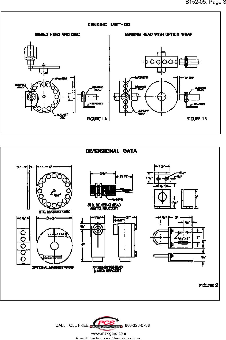
4 B152-05, Page Mounting the Sensing Head 3.1 Place the sensing head so the sensor is centered directly in front of the magnets of the disc or optional wrap. (see figure 1A & 1B, page 3). 3.2 The gap setting between the sensor and magnet disc should be approximately 1/8-3/ The sensing head comes standard with 10 of cable. If additional cable length is required, be sure to maintain continuity. 4.0 Meter Installation 4.1 Cut meter cutout and drill mounting holes according to the layout dimensions. (see figure 3A and 3B, page 4) 4.2 Install meter horizontally and use hardware provided to secure meter to panel.

5 B152-05, Page 5 SECTION 2 - FIELD WIRING 5.0 Wiring and Energizing 5.1 Sensing Head Connect sensing head cable leads to terminal block TB1, located on the circuit board. (see figure 4, page 5) The sensing head comes standard with 10 of cable. Additional cable can be added up to Maintain continuity and make good splices. Sensing head cable, use Belden #8771 or equal. Cable should not be run in same conduit as power lines. Maximum distance of cable run, Meter (Analog) Remove shunt wire from between meter poles located on the back side of meter Make meter wire connections between terminal block TB1 and the (+) and (--) poles located on the back of the meter. (see figure 5, page 6 and figure 3A, page 4)
 5.2.1 Remove shunt wire from between meter poles located on the back side of meter. 5.2.2 Make meter wire connections between terminal block TB1 and the (+) and (--) poles located on the back of the meter.")
6 B152-05, Page Calibrating the Tachometer Circuit Board Connect 115 VAC power to terminals L1 and L2 of terminal block TB1. WARNING Be sure line voltage is off before connecting power Check sensing head installation and gap setting. (see figure 1A and 1B, page 3) WARNING Proceed with caution, 115 VAC is present and could result in an electrical shock injury or death. CAUTION Beware of moving machinery, could result in accidental injury Start the monitored machine and run at the normal high operating speed and apply 115 VAC to the calibration circuit board.

7 B152-05, Page Dip Switch Setting Sample and Hold Up Date Time Select the speed range chart that represent your operating speed range, (0-50 RPM range or 50-10,000 RPM range). (see figure 6, page 7 and figure 7, page 8) Locate the Speed Range Dip Switch on the calibration circuit board Set the dip switches to match your general speed range. Low range or High Range. (see figure 6, page 7 and figure 7, page 8) 1. Switches 5 & 8 will always be on for the LOW range. 2. Switches 6 & 8 will always be on for the HIGH range. 3. Switch 7 will always be off for BOTH ranges Select the dip switch setting that allow for the most steady meter reading. See example 1, page 8, low speed range and see example 2, page 9, high speed range Make final meter calibration by adjusting POT P1, located on the circuit board. C.W. or C.C.W. to increase or decrease the meter reading.

8 B152-05, Page Other up date times are available by different combinations of dip switch settings. EXAMPLE: LOW SPEED RANGE (0-50 RPM) SWITCHES = 1+3+(5+8) ON = 10 sec. up date = (5+8) ON = 30 sec. up date 1. Switches 5 & 8 are always on for the LOW speed range, 0-50 RPM. 2. Switch 7 is always off. 3. Try different switch combinations for the most steady meter reading - the longer the up date time, the steadier the reading Make final meter calibration by adjusting POT P1.

9 B152-05, Page Other up date times are available by different combinations dip switch settings. EXAMPLE: HIGH SPEED RANGE (50-10,000 RPM) SWITCHES = 1+3+(6+8) ON =.65 sec. up date = (6+8) ON = 1.95 sec. up date 1. Switches 6 & 8 are always on for the HIGH speed range ,000 RPM. 2. Switch 7 is always off. 3. Try different switch combinations for the most steady meter reading - the longer the up date time, the steadier the reading Make final meter calibration by adjusting POT P1. OPTIONAL SIGNAL TRANSMITTER 4/20 ma OR 0-10 VDC OUTPUT The Signal Transmitter has been calibrated and factory tested (as accurately as possible) to match your operating speeds and output requirements. However, final calibration will be required during installation and start up. This final calibration is made by adjusting the Zero and Span Pots., located on the Signal Transmitters plug-in circuit board. The Signal Transmitter will have the same up date time as the tachometer. (see figure 8, page 10)
 to match your operating speeds and output requirements.")
10 B152-05, Page Signal Calibration 4/20 ma or 0-10 VDC Outputs Use a digital or analog voltmeter to calibrate the transmitter /20 ma Output Set the voltmeter on the millamp current scale adequate for 4/20 ma calibration Attach the voltmeter positive and negative leads to terminal block TB Apply power to the circuit board and monitor machine at -0- speed, adjust the Zero Pot P2, C.W. or C.C.W. until voltmeter reads 4 ma Power on and monitored machine running at full speed, adjust Span POT P3, C.W. or C.C.W. until voltmeter reads 20 ma VDC Output Set voltmeter to the DC voltage range adequate for 0-10 VDC calibration Connect voltmeter leads to terminal block TB Apply power to the circuit board and monitor machine at -0- speed, adjust the Zero POT P2, C.W. or C.C.W. until voltmeter reads -0- volts Power on and monitored machine running at full speed, adjust Span POT P3, C.W. or C.C.W. until voltmeter reads 10 volts. WARNING Proceed with caution, 115 VAC is present and could result in electrical shock which may cause injury or death.

11 B152-05, Page 11 Part No. SPARE PARTS LIST Description 1323 Circuit Board, Calibration Card 1390 Sensing Head, W/10 of Cable, (Std) Hall Effect 1130 Mounting Bracket and Jam Nuts (Std) 1391 Sensing Head, W/10 Cable, (XP) Hall Effect 1134 Mounting Bracket (XP) 1136 Magnet Disc (4 Diameter) 1378 Magnet Disc (8 Diameter) 1177 Meter, Tachometer (Analog) Spec. Scale 1363 Meter, Tachometer (Analog) Single Set Point 1362 Meter, Tachometer (Analog) Dual Set Point 1324 Meter, Tachometer (Digital) 3 1/2, LED 1361 Meter, Tachometer (Digital) 4 1/2, LED 1157 Cable, Sensing Head, 3 W 1574 Circuit Board, 4/20 ma Card LIMITED WARRANTY Process Control Systems, Inc. will repair or replace, at their option, F.O.B. factory, any part or unit which proves to be defective in material or workmanship within five years of purchase date, provided that part of the unit was installed and operated as recommended, to be established by examination of the part or unit at the factory. Goods returned under warranty must be shipped prepaid to the factory and accompanied by the serial number, description of defect, order number and date of purchase. This warranty shall not apply to any Maxigard TM product which shall have been repaired or altered outside of the Process Control Systems factory or has been subject to misuse, negligence or accident. Process Control Systems, Inc. warrants its products, but not their application, and shall not be liable for any incidental or consequential damages incurred through the use or loss of use of a Process Control Systems product. No representatives or other person is authorized or permitted to make any warranty or assume for this company any liability not strictly in accordance with this guarantee. There is no further warranty either expressed or implied beyond that set forth herein.
 Single Set Point 1362 Meter, Tachometer (Analog) Dual Set Point 1324 Meter, Tachometer (Digital) 3 1/2, LED 1361 Meter, Tachometer (Digital) 4 1/2, LED 1157")
Model SRMD Setra Remote Monitoring Display
 Model SRMD Setra Remote Monitoring Display 1.0 GENERAL INFORMATION Thank you for purchasing the Setra Remote Monitoring Display (SRMD). The SRMD is a digital panel meter with a bright 1 LED display for
Advantium 2 Plus Alarm
 ADI 9510-B Advantium 2 Plus Alarm INSTALLATION AND OPERATING INSTRUCTIONS Carefully Read These Instructions Before Operating Carefully Read These Controls Corporation of America 1501 Harpers Road Virginia
Global Water Instrumentation, Inc.
 Global Water Instrumentation, Inc. 11390 Amalgam Way Gold River, CA 95670 T: 800-876-1172 Int l: (916) 638-3429, F: (916) 638-3270 Solar Panels 2 Watt Solar Panel: SP101 5 Watt Solar Panel: SP102 01-752
Installation and Operation Guide for PD4100 Series Power Control Centers
 Installation and Operation Guide for PD4100 Series Power Control Centers Extended warranties are available for purchase at www.progressivedyn.com Member Thank you for selecting Progressive Dynamics as
12-Volt Negative Ground Installation Instructions
 12-Volt Negative Ground Installation Instructions For Part Number: 1141, 1164, 1165, 1181 CAUTION!!! Before installing, please read the following important information... 1. The Ignitor is designed for
Comfort Control Relay Panel (CCRP)
") CCRP9 "Commitment to Innovation" OPERATION & INSTALLATION GUIDE FOR Comfort Control Panel (CCRP) Off-Peak System Control 9 Pole CCRP 4 Pole CCRP (Applicable to Software Version 14.0-14.9) "Manufactured
CCRP9 "Commitment to Innovation" OPERATION & INSTALLATION GUIDE FOR Comfort Control Panel (CCRP) Off-Peak System Control 9 Pole CCRP 4 Pole CCRP (Applicable to Software Version 14.0-14.9) "Manufactured
Installation and Operation Guide for PD4000 Series Power Control Center
 Extended warranties are available for purchase at www.progressivedyn.com Installation and Operation Guide for PD4000 Series Power Control Center Member Thank you for selecting Progressive Dynamics as your
Part I - Installation
 400 Series Pressure and Differential Pressure Switches Types: H400, H402, H403, H400K, H402K, J400, J402, J403, J400K, J402K UNITED ELECTRIC CONTROLS Installation and Maintenance Instructions Please read
VK-250 WARRANTY REGISTRATION FORM
 VK-250 WARRANTY REGISTRATION FORM Unit Serial Number: Customer Name: Address: Date of Purchase: Purchased From: Dealer Name: Address: IMPORTANT NOTE: In order to receive the full five year product warranty,
RI-215A Operator s Manual. Part Number: 71-0045RK Revision 0 Released: 10/3/05
 RI-215A Operator s Manual Part Number: 71-0045RK Revision 0 Released: 10/3/05 Warranty RKI Instruments, Inc., warrants gas alarm equipment sold by us to be free from defects in materials and workmanship,
BLWR23MDA Series. 24V, 15A Brushless Controller / Motor. User s Guide. 910 East Orangefair Lane, Anaheim, CA 92801 e-mail: info@anaheimautomation.
 BLWR23MDA Series 24V, 15A Brushless Controller / Motor User s Guide A N A H E I M A U T O M A T I O N 910 East Orangefair Lane, Anaheim, CA 92801 e-mail: [email protected] (714) 992-6990 fax:
ALL WEATHER W-SERIES QUARTZ TUBE ELECTRIC INFRARED RADIANT HEATER INSTALLATION USE & CARE MANUAL
 ALL WEATHER W-SERIES QUARTZ TUBE ELECTRIC INFRARED RADIANT HEATER TABLE OF CONTENTS: INSTALLATION USE & CARE MANUAL IMPORTANT INFORMATION Assembly Instructions 2 Wiring Instructions 2 Outdoor Installation
OEM Manual MODEL 2350 ELECTRONIC DUAL CYLINDER SCALE
 OEM Manual MODEL 2350 ELECTRONIC DUAL CYLINDER SCALE Scaletron Industries, Ltd. Bedminster Industrial Park 53 Apple Tree Lane P.O. Box 365 Plumsteadville, PA 18949 USA Toll Free: 1-800-257-5911 (USA &
WATERBUG@ INSTALLATION / OWNERS MANUAL MODEL WB-200. PN # D-01 l-0007
 WATERBUG@ INSTALLATION / OWNERS MANUAL MODEL WB-200 PN # D-01 l-0007 REV B INTRODUCTION Thank you for your purchase of the Winland WaterBug@ mode I WB-200. The WaterBug@ is completely electronic and is
Model RPM10 Laser Photo / Contact Tachometer with IR Thermometer Patented
 User's Guide Model RPM10 Laser Photo / Contact Tachometer with IR Thermometer Patented Introduction Congratulations on your purchase of Extech's Laser Photo/Contact Tachometer with Non- Contact IR Thermometer,
INSTALLATION INSTRUCTIONS BOOST CONTROLLER. Pro Control Input (Optional) Tach. Signal. Speed. Gray. Signal. Green Blue. Orange.
 Tach. Signal. Speed. Gray. Signal. Green Blue. Orange.") 2650-1706-00 INSTALLATION INSTRUCTIONS BOOST CONTROLLER WARNING! The installation of the Auto Meter Boost Controller is recommended only for experienced technicians. This product may damage your engine
2650-1706-00 INSTALLATION INSTRUCTIONS BOOST CONTROLLER WARNING! The installation of the Auto Meter Boost Controller is recommended only for experienced technicians. This product may damage your engine
AT&T. PARTNER Plus Door Phone. Installation and Operation Manual
 AT&T PARTNER Plus Door Phone Installation and Operation Manual Copyright 1990 AT&T All Rights Reserved Printed in U.S.A. CIC# 999-500-317 OII722050-051 Issue 1 October 1990 PARTNER Plus Door Phone is a
DORMA MODEL PS-406BB POWER SUPPLY INSTALLATION INSTRUCTIONS
 Features: INSTALLATION Install in accordance with NFPA 70. DORMA MODEL PS-406BB POWER SUPPLY INSTALLATION INSTRUCTIONS Up to 1.95 Amps Load Capacity Class 2 Rated Outputs Overload, Over Voltage, and Short
AEROMOTIVE Part # 16302 INSTALLATION INSTRUCTIONS
 AEROMOTIVE Part # 16302 INSTALLATION INSTRUCTIONS CAUTION: Installation of this product requires detailed knowledge of automotive systems and repair procedures. We recommend that this installation be carried
Installation and Operation Guide for PD5100 Automatic Transfer Switch
 Installation and Operation Guide for PD5100 Automatic Transfer Switch Member P r o gr e ssive Dynamics, Inc. 507 Industrial Rd Marshall, MI 49068 www.progressivedyn.com 2012 Progressive Dynamics, Inc.
WINEGARD MOTORIZED SENSAR ANTENNA Models MA1055W & MA1055G MADE IN U.S.A. U.S. Patents D500,496 and 7,358,909 INSTALLATION MANUAL
 WINEGARD MOTORIZED SENSAR ANTENNA Models MA1055W & MA1055G MADE IN U.S.A. U.S. Patents D500,496 and 7,358,909 INSTALLATION MANUAL CAUTION: This system is not for use with antenna in raised position while
SFS81 Series. Servo Finishing Stand PUSHCORP, INC. Dallas, Texas
 SFS81 Series Servo Finishing Stand PUSHCORP, INC. Dallas, Texas May, 2012 NEVER OPERATE THE SFS81 MANUALLY NEVER OPERATE THE SFS81 WITH PERSONEL IN THE WORKCELL DO NOT USE LUBRICATED AIR. This device requires
16/32 Channel 1U Rack Mount CCTV Power Supply
 16/32 Channel 1U Rack Mount CCTV Power Supply Manual PH-A3224-GUQ Shown 16-Channel 32-Channel PTC PH-A1612-PUQ PH-A3224-PUQ Glass Fuse PH-A1612-GUQ PH-A3224-GUQ Industrial design 12 Amp 3 Amps per channel
LiteAide OWNER'S MANUAL PREASSEMBLED AUTOMATIC SECURITY FLOODLIGHTS MOTION SENSOR SECURITY LIGHTING SYSTEMS
 OWNER'S MANUAL PREASSEMBLED AUTOMATIC SECURITY FLOODLIGHTS MOTION SENSOR SECURITY LIGHTING SYSTEMS LiteAide HE-100B HE-100BW HE-112 HE-112W HE-117 HE-117W HE-117-2B OWNER'S MANUAL FLOOD LAMPS (BULBS) Your
OPL BASIC. Dosing System for Professional Laundry machines. Contents
 OPL BASIC Dosing System for Professional Laundry machines Contents 1 Getting Started. Page 2 2 Installation. Page 4 3 Set Up & Operation. Page 8 4 Maintenance & Accessories. Page 10 5 Troubleshooting Page
Utility Distribution Systems
 Utility Distribution Systems 6/2012 A0011037 1 WARRANTY This equipment is warranted to be free from defects in materials and workmanship, under normal use and service, for a period of 12 months from date
User's Manual. Research Isometric Transducer 0 to 5 grams and 0 to 50 grams
 Research Isometric Transducer 0 to 5 grams and 0 to 50 grams User's Manual Research Isometric Transducer 0 to 5 g and 0 to 50 g, 110 VAC/60 Hz MA1 72-4481 Research Isometric Transducer 0 to 5 g and 0 to
Installation and Operating Manual
 DC DRIVE BC138 BC139 DC CONTROL Installation and Operating Manual 7/2001 MN708 TABLE OF CONTENTS Section Page i. Simplified Operating Instructions.......................................... 1 ii. Safety
 MEDION LIMITED WARRANTY Medion warrants that the product accompanied by this limited warranty is free from manufacturing defects in material or workmanship for a period of 12 months from the date of original
MDC151-024031 Series
 MDC151-024031 Series 24V, 3A Brushless DC Controller User s Guide A N A H E I M A U T O M A T I O N 910 East Orangefair Lane, Anaheim, CA 92801 e-mail: [email protected] (714) 992-6990 fax: (714)
BLY17MDA Series. 24V, 10A Brushless Controller/Motor. User s Guide. 910 East Orangefair Lane, Anaheim, CA 92801 e-mail: info@anaheimautomation.
 BLY17MDA Series 24V, 1A Brushless Controller/Motor User s Guide A N A H E I M A U T O M A T I O N 91 East Orangefair Lane, Anaheim, CA 9281 e-mail: [email protected] (714) 992-699 fax: (714) 992-471
LST-3800. In-Dash Digital Sonar Gauge. Installation & Operation Instructions
 Pub. 988-0064-351 LST-3800 In-Dash Digital Sonar Gauge Installation & Operation Instructions The LST-3800 is a depth and temperature gauge that comes with a 200 khz transducer, features deep and shallow
Periodic Verification System Model 775PVS
 Periodic Verification System Model 775PVS Instruction Manual Contents 1 Description... 1 775PVS System... 1 Model 775 Fieldmeter... 2 Model 775C Charger... 2 Model 775P Plate Assembly... 3 2 Operation...
J o y s t i c k s. JS - 2050 - HD series. mechanical. www.cyber-tech.net 1-800-621-8754
 The Cyber-Tech JS-2050-HD mechanical joystick is tough, reliable, INDUSTRIAL CONTROL SOLUTIONS Handy-Grips Ergo-Grips Joystick Bases P.O Box 23801 Portland, Or 97281-3801 7943 SW Cirrus Dr. Beaverton,
BroadBand PowerShield. User Manual
 BroadBand PowerShield User Manual 990-0375G 12/2006 Chapter 1 General Information The PowerShield provides a power source for broadband telephony and other DC applications. Safety This Safety Guide contains
Installation, Operation & Service Manual
 Installation, Operation & Service Manual 0RQLWRU Pulse Monitor Software Version 1 0 1 Pulse Monitor Card Software Revision 1 4 0 Pulse Monitor Card Product Revision 0 1 0 0 February, 2007 Copyright 2007,
Installation and Operation Guide PD4600 Series Converter Replacement
 Installation and Operation Guide PD4600 Series Converter Replacement Extended warranties are available for purchase at www.progressivedyn.com Member Thank you for selecting Progressive Dynamics as your
Water Leak Detection System
 Water Leak Detection System Installation and Operating Manual 505-334-5865 ph 505-334-5867 fax www.rodisystems.com email:[email protected] 936 Highway 516 Aztec, NM 87410-2828 Manual Revisions and Copyright
DUSTTRAK AEROSOL MONITOR SOLAR POWER KIT MODEL 854060
 DUSTTRAK AEROSOL MONITOR SOLAR POWER KIT MODEL 854060 (FOR DUSTTRAK II AND DRX AEROSOL MONITOR MODELS 8540 AND 8543) OPERATION AND MAINTENANCE MANUAL P/N 6008416, REVISION A MAY 2015 Copyright TSI Incorporated
Machine Safety Switch: SI-LM40 Series Limit Switch Style
 Machine Switch: SI-LM40 Series Limit Switch Style SI-LM40 Series Limit Switch Style with Flexible In-Line Actuator Positive-opening safety contacts (IEC 60947-5-1) (not dependent upon springs) Standard
Solar Power Systems Models: PVS220W-24 and PVS220W-48 Installation Manual
 Solar Power Systems Models: PVS220W-24 and PVS220W-48 Installation Manual 255379 Rev. D0 1015 Printed in U.S.A. Copyright 2015 Federal Signal Corporation Limited Warranty The Alerting and Notification
SOLAR ELECTRIC MODULE ES-124 & ES-62T Owners Manual and Installation Guide
 SOLAR ELECTRIC MODULE ES-124 & ES-62T Owners Manual and Installation Guide circuit. Reverse connection will damage the module and may result in fire. CAUTIONS Solar electric modules produce DC electricity
INSTALLATION & OPERATION MANUAL LED
 INSTALLATION & OPERATION MANUAL LED Duo Beam TM Introduction... 2 Lightbar Unpacking & Pre-Installation... 2 Installation & Mounting... 3 Wiring Instructions... 4 Maintenance... 4 Flash Pattern Selection...
Transmitter Interface Program
 Transmitter Interface Program Operational Manual Version 3.0.4 1 Overview The transmitter interface software allows you to adjust configuration settings of your Max solid state transmitters. The following
ATS Overhead Table Shelf System INSTRUCTION MANUAL
 ATS Overhead Table Shelf System INSTRUCTION MANUAL ATS Overhead Table Shelf System Instruction Manual Warranty Newport Corporation warrants this product to be free of defects in material and workmanship
INSTRUCTION MANUAL MODEL PCD-88
 INSTRUCTION MANUAL MODEL PCD-88 CLOSED CAPTION DECODER LINK ELECTRONICS, INC. 2137 Rust Avenue Cape Girardeau, Missouri 63703 Phone: 573-334-4433 Fax: 573-334-9255 e-mail: sales @ linkelectronics.com website:
Unpacking, Installation, and Customization
 Unpacking, Installation, and Customization NetShelter WX Enclosure AR100 AR100HD Contents Unpacking... 1 How to Unpack the Enclosure............................... 1 Please Recycle..........................................
Installation and Operation Manual. Digital Remote Meter for Monitoring System Performance. Version: RM-1
 REMOTE METER TM Installation and Operation Manual. Digital Remote Meter for Monitoring System Performance. Version: RM-1 1098 Washington Crossing Road Washington Crossing, PA 18977 USA www.morningstarcorp.com
I nstallation. M100Q Series Proportional Actuator with R81Q Controller Board for Thermistor Sensor Applications. Tools Needed.
 FANs 268.1, 1628.3 Installation Bulletin M100Q Issue Date 1099 M100Q Series Proportional Actuator with R81Q Controller Board for Thermistor Sensor Applications I nstallation Parts Included M110QGA-1 and
User's Manual. Model 461995 Laser Photo / Contact Tachometer. Introduction
 User's Manual Model 461995 Laser Photo / Contact Tachometer Laser Photo/ Contact Tachometer 461995 MEMORY rpm PHOTO CONTACT ft/min m/min Introduction Congratulations on your purchase of Extech's Laser
Global Water Instrumentation, Inc.
 Global Water Instrumentation, Inc. 11390 Amalgam Way Gold River, CA 95670 T: 800-876-1172 Int l: (916) 638-3429, F: (916) 638-3270 Water Level Sensor: WL400 00-997 11/30/09-1 - Congratulations on your
Architect/Contractor Information Package
 Architect/Contractor Information Package 3M SelfCheck System C-Series C1 Model 877 This package provides architects and contractors with the information necessary for the successful installation of the
Installation Instructions WARNING: WARNING: WARNING: WARNING: WARNING:
 Installation Instructions Ultra-Violet Air Purifier Residential/Commercial Duct Installation Applications - RX4000, RX4000B, RX1700 SAFETY CONSIDERATIONS Installation and servicing of air-conditioning
POWER GEAR SLIDE OUT MANUAL
 POWER GEAR SLIDE OUT MANUAL Operation Guide FLUSH FLOOR SLIDE OUT SYSTEM FOR AMERICAN COACH PRODUCTS 82 S0220 01 Rev. 1 AMERICAN COACH SLIDE OUT MANUAL FLUSH FLOOR SYSTEM TABLE OF CONTENTS SECTION PAGE
VDO ELECTRONIC SPEEDOMETER HALL EFFECT SENDER INSTALLATION INSTRUCTIONS AND WIRING DIAGRAM TYPE A SPEEDOMETER 4-WIRE SYSTEM 5(' %52:1 <(//2: :+,7(
 VDO ELECTRONIC SPEEDOMETER HALL EFFECT SENDER INSTALLATION INSTRUCTIONS AND WIRING DIAGRAM 7UDQVPLVVLRQ TYPE A SPEEDOMETER 4-WIRE SYSTEM Y 6:,7&+(' $&&(6625< %52:1
Installation/Operator Manual For use with WFCO ULTRA III Power Center Model WF-8712P and WF-8725P
 Installation/Operator Manual For use with WFCO ULTRA III Power Center Model WF-8712P and WF-8725P Distributed in the U.S.A. and Canada by CHENG USA, INC. Sales (574) 294-8997 Warranty Service (877) 294-8997
INSTALLATION & SERVICE MANUAL. Display Panel
 INSTALLATION & SERVICE MANUAL Display Panel The PowerLine EMS TM is a specialized power distribution and energy management system intended to be used in recreational vehicles. The Control Module is housed
Single Station Remote Alarm
 ADI 5106G Certified ISO 9001:2000 Single Station Remote Alarm 529 5106-01-120 529 5106-01-220 INSTALLATION AND OPERATING INSTRUCTIONS Carefully Read These Instructions Before Operating Controls Corporation
PixController, Inc. Wireless Digital PIR Sensor
 PixController, Inc. Wireless Digital PIR Sensor Model: SEN-400 User s Manual Version 1.00 WARRANTY REGISTRATION PixController, Inc. warrants products sold by it and guarantees to correct, by repair or
Ultrasonic Distance Meter. Operation Manual
 XPROTEC Ultrasonic Distance Meter Operation Manual About XProTec Pro-Installer Tools The XProTec line from XFTP is a comprehensive lineup of professionalgrade technical tools. These full-featured, field-proven,
FEATURES Temperature-compensated magnetics Miniature plastic package Low voltage: 3.8 V operation
 DESCRIPTION The SS400F and SS400G Series sensors are small, versatile digital Hall-effect devices that are operated by the magnetic field from a permanent magnet or an electromagnet, and are designed to
Operating Instructions
 Operating Instructions Series L 000 Cord Reels Model Numbers: L 000 L 0 0 L 0 B L 0 X L 00 L A X L 0 L 0 0 L 00 L 0 L 0 B L 0 0 X L 00 L 0 A L 0 X IMPORTANT Read this manual carefully before installing,
WARNING: FAILURE TO FOLLOW THESE RULES MAY RESULT IN SERIOUS PERSONAL INJURY CAUTION: INSTALLATION LOCATION:
 Revision Level: 01 Revision Date: 07/07/2011 Please read all instructions carefully to help ensure a correct and SAFE installation of your Second Wind Ultraviolet Germicidal Air Purifier. Failure to do
INSTALLATION GUIDE LOW VOLTAGE TRANSFORMER
 INSTALLATION GUIDE LOW VOLTAGE TRANSFORMER 300W 600W 900W 1200W ATTENTION: Please read and understand thoroughly this installation guide to ensure safe and efficient operation of this Power Module 1 Open
Ordering Part Numbers: Universal Signal Converter: USC-CVB225-01 Universal Signal Converter with a 4-20mA input and +/- 10V output: USC-CVB225-B10V
 Description: The universal signal converter offers threeway isolation and translates one input control signal into one to three simultaneous outputs. Switches allow the user to select the desired input
MSD Pro-Billet Ready-to-Run Chevrolet V8 Distributor, PN 8360 Chevrolet 348, 409 Distributor, PN 8393
 MSD Pro-Billet Ready-to-Run Chevrolet V8 Distributor, PN 8360 Chevrolet 348, 409 Distributor, PN 8393 ONLINE PRODUCT REGISTRATION: Register your MSD product online and you ll be entered in our monthly
SKILL ATTACK PITCHING MACHINE PATENTS APPLIED FOR INSTRUCTION MANUAL. Includes: OPERATION SETUP USE & CARE SERVICE
 VOLLEYBALL SKILL ATTACK PITCHING MACHINE PATENTS APPLIED FOR INSTRUCTION MANUAL Includes: OPERATION SETUP USE & CARE SERVICE REV032813 SPORTS ATTACK, LLC. 800-717-4251 sportsattack.com WARRANTY STATEMENT
For Models #6-5001, #6-7501, #10-7501 & #10-12K1
 EmerGen Switch Manual Transfer Switch Manufactured by CONNECTICUT ELECTRIC SWITCH MFG. CO. 1-800-730-2557 OWNER S MANUAL & INSTALLATION INSTRUCTIONS For Models #6-5001, #6-7501, #10-7501 & #10-12K1 PLEASE
MTV-FS1 / FS1T / FSB375
 MTV-FS1 / FS1T / FSB375 MYE Entertainment Freestanding LCD TV Floor Stand with Base Assembly Instructions man_mtvfs1_b3 www.myeclubtv.com Table of Contents Parts List 3 Parts Identification......3 Hardware
CONTENTS. PAGE Chapter 1 General Information 1. Chapter 2 Setup 4 DP450-VDC 7 DP450-VAC 7 DP450-DCC 7 DP450-F 8 DP450-HACC 9 DP450-HDCC 11 DP450-E 13
 CONTENTS PAGE Chapter 1 General Information 1 Chapter 2 Setup 4 DP450-VDC 7 DP450-VAC 7 DP450-DCC 7 DP450-F 8 DP450-HACC 9 DP450-HDCC 11 DP450-E 13 Chapter 3 Alarm/Excitation Options 15 Wiring 17 Chapter
INSTALLER S & OWNER S MANUAL
 INSTALLER S & OWNER S MANUAL HVAC INSTALLER: PLEASE LEAVE MANUAL FOR HOMEOWNER DEH 3000 DEH 3000 Part No. 4028539 Dehumidifier & Ventilation System Controller P.O. Box 8680 Madison, WI 53708 TOLL-FREE
CruzPro VAF110. AC Volts, Amps, Frequency, kw Monitor
 CruzPro VAF110 AC Volts, Amps, Frequency, kw Monitor Table of Contents Introduction............................ 3 Specifications........................... 4 Installation..............................5
How To Size A Stenner Pump
 Metering Pumps Manufactured Since 1957 PCM Series Pump Control Module INSTALLATION AND MAINTENANCE MANUAL Table of Contents WarrantyandServicePolicy...3 Safety Information...............................................
Owner s Manual & Safety Instructions
 Owner s Manual & Safety Instructions Save This Manual Keep this manual for the safety warnings and precautions, assembly, operating, inspection, maintenance and cleaning procedures. Write the product s
 0150506194 C Limited 2nd through 5th Year Functional Parts Warranty During the 2nd through 5th year,haier will provide functional parts which prove to be defective due to workmanship
Multi-Pitch Pitching Machine USER MANUAL
 Multi-Pitch Pitching Machine USER MANUAL TABLE OF CONTENTS Thank you for purchasing the Cimarron Multi-Pitch Pitching Machine. The Cimarron Multi-Pitch Pitching Machine is a high performance pitching machine
Service Information CALIBRATION PROCEDURE AND TROUBLESHOOTING FOR LINEAR GOVERNOR CONTROLLERS NOTE
 Service Information Calibration & Adjustments CALIBRATION PROCEDURE AND TROUBLESHOOTING FOR LINEAR GOVERNOR CONTROLLERS Part Number DYN1-10752-000-0-12/24 DYN1-10752-001-0-12/24* DYN1-10753-000-0-12/24
About this Manual. Support for Your Product
 About this Manual We ve added this manual to the Agilent website in an effort to help you support your product. This manual is the best copy we could find; it may be incomplete or contain dated information.
Sierra Dual 24 Volt Brushless DC Motor Controller Product Specification
 Sierra Dual 24 Volt Brushless DC Motor Controller Product Specification Assembly 025A0215 600A0942 Rev. A May 14, 2012 025A0215 Brushless DC Motor Controller Page 1 Revision History ECN # Date Rev Description
Electrically Released Brake ER-825, ER-1225 with Pin Drive Armatues for Montgomery Kone
 P-230 819-0466 Electrically Released Brake ER-825, ER-1225 with Pin Drive Armatues for Montgomery Kone Installation & Operating Instructions Contents Introduction........................... 3 Installation
6 & 12 Volt Battery and Systems Tester with 100 Amp Load
 6 & 12 Volt Battery and Systems Tester with 100 Amp Load Form No. 841-731 -000 DESCRIPTION This Load Tester tests 6 or 12 volt automotive-size lead-acid batteries under load. It will also test 6 or 12
User Manual. Instructions for installing the Sure Stitch on the Next Generation Quilting Frame. Parts Included:
 User Manual Instructions for installing the Sure Stitch on the Next Generation Quilting Frame. Parts Included: 1: Display Console 1: Control Box 2: Encoder (Wires attached) (Not Shown) 1: 5v Power Supply
Owner's Manual [ S/N LABEL HERE ] Document # BW-BCU5DOC
![Owner's Manual [ S/N LABEL HERE ] Document # BW-BCU5DOC](/thumbs/39/18146231.jpg "Owner's Manual [ S/N LABEL HERE ] Document # BW-BCU5DOC") Owner's Manual [ S/N LABEL HERE ] Document # BW-BCU5DOC BAYweb Remote Model BW-BCU5 Owner's Manual Copyright 2009-2010 Bay Controls, LLC Part Number: BW-BCU5DOC Revision: 0.2 April 18, 2010 BAYweb is a
Owner's Manual [ S/N LABEL HERE ] Document # BW-BCU5DOC BAYweb Remote Model BW-BCU5 Owner's Manual Copyright 2009-2010 Bay Controls, LLC Part Number: BW-BCU5DOC Revision: 0.2 April 18, 2010 BAYweb is a
VARI-DRIVE NEMA1 / IP20 SCR Variable Speed DC Motor Controls
 TM TM INSTALLATION AND OPERATING INSTRUCTIONS VARI-DRIVE NEMA1 / IP20 SCR Variable Speed DC Motor Controls Model KBWM-120 rated 1/100-1/3 HP (90 Volts DC) @ 115 Volts AC, 50/60 Hz Model KBWM-240 rated
3M Wrist Strap and Footwear Tester 740. User s Guide
 3M Wrist Strap and Footwear Tester 740 User s Guide Table of Contents Section Page Safety Information...3 1.0 General...4 2.0 Description...4 3.0 Operation...5 4.0 Wall Mounting...5 5.0 Wrist Strap Test...6
IR Repeater. Operation Manual P8620
 IR Repeater Operation Manual P8620 Congratulations on your purchase of the P8620 IR Repeater. This operating manual will provide a guide to installation and operation of the product. Please read thoroughly
Installation and User s Manual Global Tracking and Tracing System. GTTS-2000Bi
 Installation and User s Manual Global Tracking and Tracing System GTTS-2000Bi Version 1.4 - January 2016 T +31570 606088 E [email protected] W www.gtts.eu Page 1 of 11 1. Preface The information in this Installation
Wireless Indoor/ Outdoor Thermometer
 Wireless Indoor/ Outdoor Thermometer Owner s Manual Please read before using this equipment. ˆ Contents FCC Information... 3 FCC Declaration of Conformity... 5 Preparation... 5 Installing Batteries...
Single Phase Soft Starter
 Single Phase Soft Starter Installation & Operating Manual 6/02 Table of Contents Section 1 General Information................................................... 1 1 General Description................................................
Operation and Installation Manual
 Operation and Installation Manual RCM-10 Remote Control Monitor and RSM-10 Remote Status Monitor for the CNA-100 & CNA-200 Automations Revision 1.1 9/98 WARRANTY INFORMATION The RCM-10 Remote Control
Owner s Manual & Safety Instructions
 Owner s Manual & Safety Instructions Save This Manual Keep this manual for the safety warnings and precautions, assembly, operating, inspection, maintenance and cleaning procedures. Write the product s
EtherNet-RS232/485. London Electronics Limited. Ethernet to RS232 or RS485 data converter. Connection details and general information
 London Electronics Limited Warren Court, Chicksands, Shefford, Bedfordshire SG17 5QB Tel +44(0)1462-850967 Fax +44(0)1462-850968 www.london-electronics.com [email protected] Ethernet to RS232
700/732 SERIES. 5mm HOUR METERS & COUNTERS. CURTIS INSTRUMENTS, INC. 200 Kisco Avenue, Mt. Kisco, NY 10549 Tel. (914) 666-2971 FAX (914) 666-2188
 666-2971 FAX (914) 666-2188") 700/732 SERIES CURTIS INSTRUMENTS, INC. 200 Kisco Avenue, Mt. Kisco, NY 10549 Tel. (914) 666-2971 FAX (914) 666-2188 www.curtisinst.com 53004 REV F 06/02 5mm HOUR METERS & COUNTERS Read Instructions Carefully
700/732 SERIES CURTIS INSTRUMENTS, INC. 200 Kisco Avenue, Mt. Kisco, NY 10549 Tel. (914) 666-2971 FAX (914) 666-2188 www.curtisinst.com 53004 REV F 06/02 5mm HOUR METERS & COUNTERS Read Instructions Carefully
cbperformance.com Please read this entire brochure prior to installing your CB Performance Products MAGNASPARK II distributor.
 - Easy -wire installation with no external spark box necessary, but can be used with one. - Precision CNC machining and hand assembled construction. This is a premium product. - Accurate super hot spark
SingleNet Single Cable Control System
 Single Cable Control System Economical, Reliable and Expandable Two-Wire Single Cable System DRIP/MICRO IRRIGATION PRODUCTS Single Cable Control System System Manager or Irrigation Controller Controls
Master Time Clock MTC-200 MTC-400 MTC-600. Users Manual
 Master Time Clock MTC-200 MTC-400 MTC-600 Users Manual Toll Free (888)713-0373 Phone (972)987-4408 FAX (877)720-9291 www.midwest-time.com [email protected] TABLE OF CONTENTS TOPIC PAGE GENERAL DESCRIPTION
Installation Guide. WSD-100 Wind Speed and Direction Sensor For XR5 Data Loggers. February, 2011
 WSD-100 Wind Speed and Direction Sensor For XR5 Data Loggers Installation Guide February, 2011 Pace Scientific Inc www.pace-sci.com Tel: 704-799-0688 [email protected] 1 Disclaimer The following warranty
User Guide. HDMI Active Cable Extender. DVI-7370c
 User Guide HDMI Active Cable Extender DVI-7370c TABLE OF CONTENTS SECTION PAGE PRODUCT SAFETY...1 PRODUCT LIABILITY...1 1.0 INTRODUCTION...2 2.0 SPECIFICATIONS...3 3.0 PACKAGE CONTENTS...4 4.0 CONNECTING