User Manual. One / One S / One S3
|
|
|
- Kathlyn Audrey Williamson
- 9 years ago
- Views:
Transcription
1 One / One S / One S3 User Manual 1

2 One / One S / One S3 User Manual Congratulations on your purchase of your Antec One / One S / One S3! When building a PC, it s important to use hardware you re comfortable working with. From Antec, the team behind dozens of award-winning enclosures since 1986, comes the One / One S / One S3, the gaming case that gives you everything you need right out of the box at an attractive price. This enclosure is stocked with features you value USB 3.0, ample cooling and tool-less 5.25 & 3.5 drive bays so that you can put your PC together with ease and get to the fun stuff. If you re looking for high quality gaming essentials at an affordable cost, then this enclosure is the One for you. The One / One S / One S3 does not include a power supply. Make sure you choose a power supply that is compatible with your computer components and has a long enough power harness to reach your motherboard and peripheral devices. We recommend our High Current Gamer or Earthwatts power supplies for the latest ATX specification compliance, broad compatibility, and power savings capability. At Antec, we continually refine and improve our products to ensure the highest quality. As such, your new chassis may differ slightly from the description in this manual due to improvements applied for the optimal building experience. As of the date of publication, all features, descriptions, and illustrations in this manual are correct. Disclaimer This manual is intended only as a guide for Antec s computer enclosures. For more comprehensive instructions on installing the motherboard and peripherals, please refer to the manuals that come with those components. 2

3 Table of Contents Section 1: Introduction 1.1 Getting to Know Your Chassis Chassis Specifications Included Screws... 7 Section 2: Hardware Installation 2.1 Setting Up Removing the Side Panels and Front Bezel Motherboard Installation Installing KUHLER H 2 O Liquid Coolers Power Supply Installation External 5.25 Device Installation Internal 2.5 Device Installation Internal 3.5 Device Installation Cable Management Section 3: Front I/O Ports 3.1 USB AC 97 / HD Audio Ports Power Switch / Reset Switch / Hard Disk Drive LED Connectors Rewiring Motherboard Header Connections Section 4: Cooling System 4.1 Included Fans Optional Fans Air Filters

4 Section 1 Introduction One / One S / One S3 User Manual 4

5 1.1 Getting to Know Your Chassis One One S / One S x 5.25 drive bays 2. 5 x 3.5 drive bays 3. 2 x 2.5 drive bays 4. 1 x 120 mm top exhaust fan (standard) 5. 1 x 120 mm rear exhaust fan (standard) 6. 1 x 120 mm side intake fan (optional) 7. 1 x 120 mm front intake fan (optional) 8. 1 x 120/140 mm bottom intake fan (optional) 9. CPU cutout 10. Motherboard mount: Standard ATX, microatx or Mini-ITX 11. Power supply mount 12. Front ports: 2 x USB 3.0, Audio In/Out 5
 9. CPU cutout 10.")
6 1.2 Chassis Specifications Chassis Type Chassis Color Dimensions Weight Cooling Mid Tower Black 17.2 (H) x 8.2 (W) x 19.2 (D) 438 mm (H) x 208 mm (W) x 488 mm (D) One: 10.8 lbs / 4.9 kg One S / One S3: 10.4 lbs / 4.7 kg One: - 1 x 120 mm top exhaust fan - 1 x 120 mm rear exhaust fan - 1 x 120 mm side intake fan (optional) - 1 x 120 mm front intake fan (optional) - 1 x 120 mm / 140 mm bottom fan (optional) One S / One S3: - 1 x 120 mm top blue LED exhaust fan - 1 x 120 mm rear exhaust fan (optional) - 1 x 120 mm side intake fan (optional) - 1 x 120 mm front intake fan (optional) - 1 x 120 mm / 140 mm bottom fan (optional) Drive Bays - 3 x 5.25 tool-less drive bays - 5 x 3.5 tool-less drive bays - 2 x 2.5 drive-bays Expansion Slots 7 Motherboard Size Front I/O Panel Standard ATX, microatx, Mini-ITX - Audio In/Out - Power and Reset buttons One / One S3: - 2 x USB 3.0 with internal motherboard connector One S: - 2 x USB 2.0 ports 6
 - 1 x 120 mm side intake fan (optional) - 1 x 120 mm front intake fan (optional) - 1 x 120 mm / 140 mm bottom")
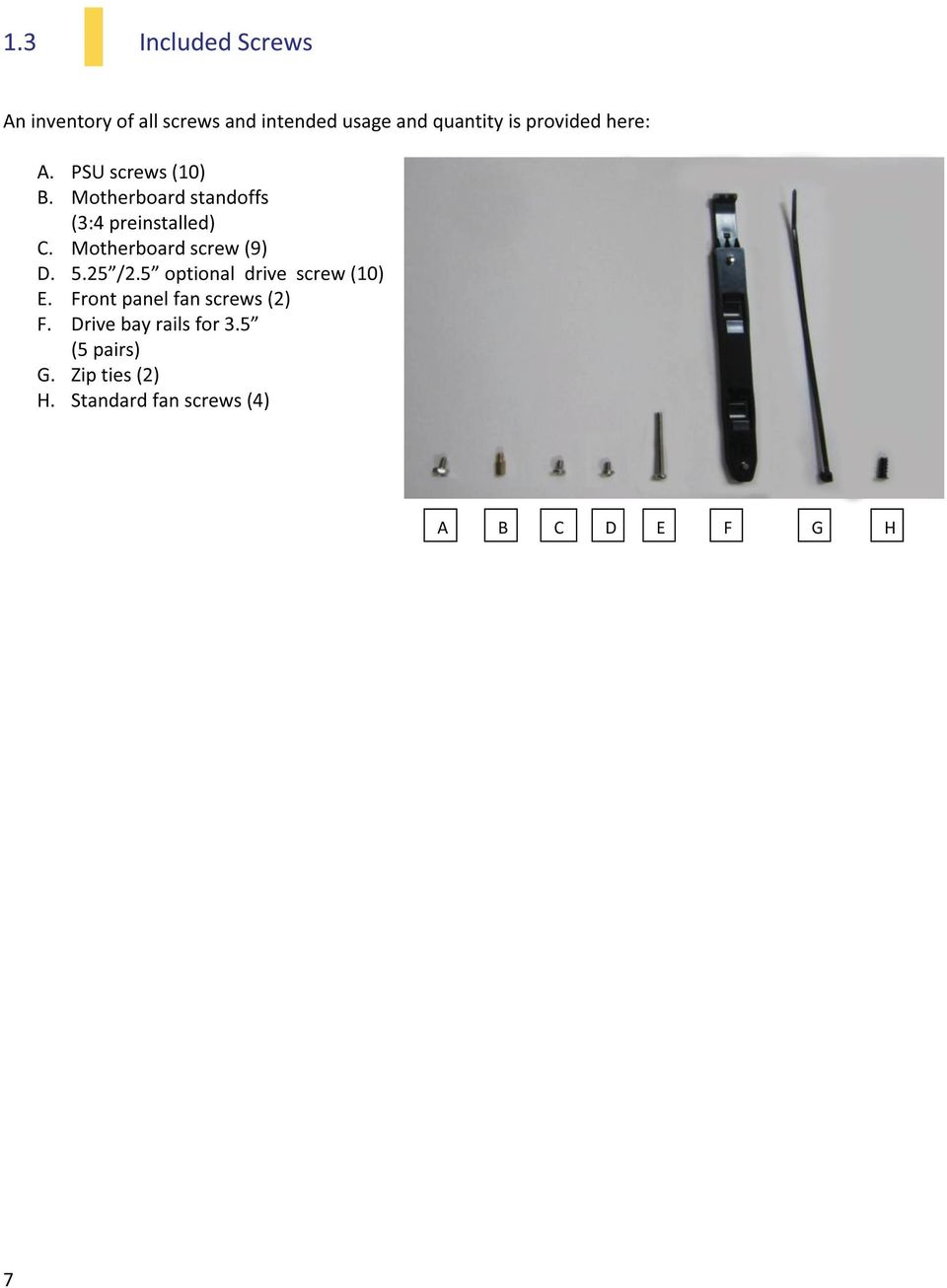
7
8 Section 2 Hardware Installation One / One S / One S3 User Manual 8

9 2.1 Setting Up When working in your case, please keep the following in mind: Put the case upright on a flat, stable surface so that the rear panel (power supply and expansion slots) is facing you. Handle all components and cards with care. To avoid electrostatic discharge, ground yourself periodically by touching an unpainted metal surface or by using a wrist grounding strap. Before you connect a cable, ensure that both connectors are correctly aligned and oriented. Do not sit on your chassis. Although it is constructed of heavy-duty steel and internally reinforced, it is not designed to support the weight of an adult, and may buckle. Do not use your fingernails to separate edges or lift the sides of the chassis, as paint chipping or injury may occur. Place the panel thumbscrews aside in a safe place. Exercise caution and control when handling chassis interiors. We strongly recommend taking the appropriate time and care when working inside the chassis. Avoid hurried or careless motions. 2.2 Removing the Side Panels and Front Bezel To remove the left and right side panels: 1. Remove each set of two thumbscrews. 2. Slide the panel you want to remove toward the back of the case approximately 2 cm until it stops. 3. Pull the panel free of the chassis. You need to remove the front bezel in order to access the air filters and conduct maintenance. To remove the front bezel: 1. Grip the bezel by the bottom and pull forward. The bezel will pop free of the chassis. 9

10 2.3 Motherboard Installation Before proceeding, check the manual for your CPU cooler to find out if there are steps you must do before installing the motherboard. Make sure you have the correct I/O panel for your motherboard. If the panel provided with the chassis isn t suitable, please contact your motherboard manufacturer for the correct I/O panel. Make sure you have the correct I/O panel. This case comes with 5 preinstalled motherboard standoffs. These are positioned for Standard ATX motherboards but can be relocated to accommodate other form factors. 1. Align the motherboard with the standoff holes on the motherboard tray and remember or mark which holes are lined up. 2. Install standoffs as needed and put the motherboard in. 3. Screw your motherboard into the standoffs with the provided motherboard mounting screws. 10

11 2.4 Installing KUHLER H 2 O Liquid Coolers The following instructs how to install the Antec KUHLER H 2 O liquid CPU cooler (620 / 920). For any other CPU coolers, please consult your manufacturer s installation guide. Caution: Check your motherboard s CPU socket to ensure its compatibility with the KUHLER H 2 O. The KUHLER H 2 O 620 / 920 is compatible with the following CPU sockets: Intel LGA 1155 / 1156 / 1366 / 2011* AMD AM2 / AM3 / AM2+ / AM3+ *Your unit may not contain the LGA 2011 mounting bracket. To receive this bracket, please contact Antec customer support (information is listed at end of manual). **Be sure to install the KUHLER H 2 O with the end of the tubes positioned at the bottom of the radiator. 1. Remove the rear fan by unscrewing the fan from the back of the chassis. 2. Preparing the KUHLER H 2 O backplate is specific to your CPU socket. Please refer to the KUHLER H 2 O installation guide, available at (KUHLER H 2 O 620) or (KUHLER H 2 O 920) for more information. 3. Prepare the retention ring according to the CPU socket you re using. 4. Complete installation according to the KUHLER H 2 O instructions. 2.5 Power Supply Installation 1. With the case upright, place the power supply in the case and align the rear of the unit with the mounting holes. 2. Attach the power supply to the case with the screws provided. Attach the power supply with the provided screws. 11
.")
12 2.6 External 5.25 Device Installation The One / One S / One S3 can support up to three 5.25 devices. 1. Remove the side panels and front bezel as directed in Section Remove the drive bay cover by pressing out on the two small tabs on either side of the cover, then pushing the cover into the front of the bezel. 3. Replace the front bezel on the front of the chassis. 4. Slide your 5.25 drive through the front of the chassis until it lines up flush with the front bezel. You will feel the drive lock into position. 5. If you need more clearance on the inside of the chassis for your drive, pull the drive bay tab on the inside of the chassis toward you and push the drive in further. Note: You can optionally secure your drive with screws for extra stability (D in Section 1.3) Slide you drive until it locks. Press down on the drive cover tabs. Pull on the tab to adjust drive bay clearance. Remove the drive bay cover. 12

13 2.7 Internal 2.5 Device Installation There are two 2.5 drive mounting locations in the One / One S / One S3: at the base of the drive cage and a dedicated mount in the middle of the drive cage. To install at the base of the drive cage: 1. Remove the side panels as described in Section Secure your drive with the 2.5 screws provided (D in Section 1.3). Your drive will attach at the base of the drive cage at the bottom of the case, with screws affixing from the underside of the case. To install in the drive cage: Note: The 2.5 drives install from the right side of the case. 1. Remove the side panels as described in Section Insert your device into the dedicated drive bay, with the connectors facing you. 3. You can optionally secure the drive to the cage with the 2.5 screws provided (D in Section 1.3) Align your drive s holes with the drive bay holes when sliding it in. Secure your drive with the provided 2.5 screws. 13

14 2.8 Internal 3.5 Device Installation The One / One S / One S3 includes 5 pairs of 3.5 drive rails. You will need 1 pair per 3.5 drive. 1. Line up the drive rail pins to the sides of your 3.5 drive. Ensure that the squeeze-tabs are aligned on the side of your drive that does not have power or data connectors. 2. Snap the rail into place. 3. Repeat steps 1-2 for the other side of the 3.5 drive. 4. Pinch the ends of the drive rails together and slide the drive into the 3.5 bay until it locks into position. This is the drive rail pin that is inserted into your 3.5 drive hole Pinch the ends of the drive rails and then slide your drive into the 3.5 bay until it locks into position. 2.9 Cable Management There is a cable management compartment between the motherboard and right side panel. You can tuck excess cables in this compartment or route them to the drive bays through one of the four conveniently-placed cable management holes. Choose the cables you would like to pass through the holes behind the motherboard tray. Pull them through the hole toward the right side of the case. Feed the cables back through the insertion point nearest the destination of the cable. 14

15 Section 3 Front I/O Ports One / One S / One S3 User Manual 15

16 3.1 USB Ports One / One S3: The One and One S3 come with two front panel USB 3.0 ports and includes an internal motherboard connector. Connect these in the same way you would a standard front panel with an internal header connector. One S: The One S comes with two front panel USB 2.0 ports. Connect these in the same way you would a standard front panel with an internal header connector. Align the connector properly to prevent damage to your motherboard Pin Signal Names Pin Signal Names 1 USB Power 1 2 USB Power 2 3 Negative Signal 1 4 Negative Signal 2 5 Positive Signal 1 6 Positive Signal 2 7 Ground 1 8 Ground 2 9 Key (No Connection) 10 Empty Pin USB 2.0 pin assignments 3.2 AC 97 / HD Audio Ports There is an Intel standard 10-pin AC 97 connector and an Intel 10-pin HDA (High Definition Audio) connector linked to the front panel of the chassis. Pin Signal Names (HDA) Pin Signal Names (AC 97) 1 MIC2L 1 MIC In 2 AGND 2 GND 3 MIC2R 3 MIC Power 4 AVCC 4 NC 5 FRO-R 5 Line Out(R) 6 MIC2_JD 6 Line Out(R) 7 F_IO_SEN 7 NC 8 Key (no pin) 8 Key (no pin) 9 FRO-L 9 Line Out(L) 10 LINE2_JD 10 Line Out(L) You can connect either the AC 97 or the HDA connector, depending on your motherboard. Locate the internal audio connectors from your motherboard or sound card and connect the corresponding audio cable. Consult your motherboard or sound card manual for the pin-out positions. Even if your system supports both standards, only use one connector. 16
 10")
17 3.3 Power Switch / Reset Switch / Hard Disk Drive LED Connectors Connected to your front panel are LED leads for power and HDD activity, as well as switch leads for the power and reset buttons. Attach these to the corresponding connectors on your motherboard. Consult your motherboard manual for specific pin header locations. For LEDs, colored wires are positive ( + ). White or black wires are negative ( ). If the LED does not light up when the system is powered on, try reversing the connection. For more information on connecting LEDs to your motherboard, see your motherboard user s manual. Front panel leads Note: Polarity (positive and negative) does not matter for switches. 17

18 3.4 Rewiring Motherboard Header Connections There may come a time when you need to reconfigure the pin-out of a motherboard header connector. Examples could be for your USB header, audio input header, or some other front panel connector such as the Power Button connector. Before performing any work, please refer to your motherboard user s manual or your motherboard manufacturer's website to confirm the pin-out needed for your connector. We strongly recommend making a notated drawing before beginning work so that you can recover if your work gets disturbed. Front panel headers Determine which wires you need to remove in order to rewire your plug to match the USB pin-outs on your motherboard (refer to your motherboard user s manual). Working on one connector at a time, use a very small flathead screwdriver or similar tool to lift up on the black tab located beside the gold posts (squares). This will allow you to easily slide out the pins from the USB plug. Working carefully so as not to damage the wires, connectors, or pins, slowly remove the pin from the connector. Repeat these steps for each wire you need to change. Working carefully so as not to damage the wires, connectors or pins, slowly insert the pin into the correct slot of the connector then snap closed the black tab that was lifted in step 1. Repeat these steps for each wire you need to change. 18

19 Section 4 Cooling System One / One S / One S3 User Manual 19

20 4.1 Included Fans One: The One comes with two standard fans (yellow outline) a rear 120 mm exhaust fan and a top 120 mm exhaust fan. The red rectangles indicate additional fan mounts. Mounting procedures for these fans is discussed in Section 4.2. One fan locations One S / One S3: The One S and One S3 come with one standard fan (yellow outline) a top 120 mm blue LED exhaust fan. The red rectangles indicate additional fan mounts. Mounting procedures for these fans is discussed in Section 4.2. One S / One S3 fan locations 120 mm Single Speed Fan Specifications Size: 120 x 25 mm fan Rated Voltage: 12V Operating Voltage: 10.8V ~ 13.2V Speed (RPM) Input Current Airflow Static Pressure Acoustic Noise Input Power A (Max.) 1.2 m³ / min (42.6 CFM) 1.0 mm-h 2 O (0.04 inch-h 2 O) 23.7 dba 2.4W 20

21 4.2 Optional Fans One: The One includes mounts for up to three more fans. These mounts are as follows: - 1 x front intake 120 mm mount - 1 x side 120 mm mount - 1 x bottom 120/140 mm mount One S / One S3: The One S / One S3 includes mounts for up to four more fans. These mounts are as follows: - 1 x front intake 120 mm mount - 1 x side 120 mm mount - 1 x bottom 120/140 mm mount - 1 x rear 120 mm mount Front intake 120 mm fan 1. Remove the front bezel as outlined in Section Align the fan with the screw holes and screw in the fan in the top-left and lower-right holes (as pictured). 3. Screw in the long fan screws (E in Section 1.3). Screw in the fan in the top-left and lower-right holes. Side 120 mm fan On the left panel, there is a 120 mm fan mount for additional graphics cards cooling. 1. Remove the left side panel as outlined in Section Align your fan with the mounting holes. The fan should be installed with air blowing into the case. 3. Screw in the fan with the included screws (H in Section 1.3). Screw the side fan into place by first aligning it with the fan screw holes. 21
22 Bottom 120/140 mm fan At the base of the case, there is a fan mount that can fit either a 120 mm or 140 mm fan for additional air intake. 1. Remove the left side panel as outlined in Section 2.2. Rest the case on its side so you have access to both sides of the fan mount. 2. Align your fan with the mounting holes. The fan should be installed on the inside of the case, with air blowing in. 3. Screw in the fan with the included screws (H in section 1.3). Screw the bottom fan into place by first aligning it with the bottom screw holes. Rear 120 mm fan One S / One S3 only A rear exhaust fan can be installed for additional airflow out of the case. 1. Remove the left side panel as outlined in Section Align your fan with the mounting holes. The fan should be installed with air blowing out of the case. 3. Screw in the fan with the included screws (H in section 1.3). 4.3 PSU Air Filter Screw the rear fan into place by first aligning it with the rear screw holes. The One / One S / One S3 features a PSU air intake filter that can be removed and cleaned. To remove the PSU filter: 1. Pull the filter out toward you using the tab at the back of the chassis. Pull the filter toward you using the tab outside the chassis. 22
23 Antec, Inc Fremont Blvd. Fremont, CA94538 tel: fax: Antec Europe B.V. Stuttgartstraat AS Rotterdam The Netherlands tel: +31 (0) fax: +31 (0) Technical Support US &Canada ANTEC Europe Copyright 2012 Antec, Inc. All rights reserved. All trademarks are the property of their respective owners. Reproduction in whole or in part without written permission is prohibited. 23
User Manual. Three Hundred Two
 Three Hundred Two User Manual 1 Three Hundred Two User Manual Congratulations on your purchase of the Three Hundred Two! The team that brought you the Three Hundred is back with an enclosure designed to
ISK600 User Manual. Congratulations on your purchase of the Antec ISK600!
 ISK600 User Manual ISK600 User Manual Congratulations on your purchase of the Antec ISK600! Sophisticated and Durable The ISK600 is the newest addition to Antec s award-winning ISK line of Mini-ITX cases.
P280 User Manual. Congratulations on your purchase of the Antec P280!
 P280 User Manual P280 User Manual Congratulations on your purchase of the Antec P280! Sophisticated and cutting-edge, the P280 emphasizes the ease of use, quiet technology and unparalleled performance
Nine Hundred. User s Manual Manuel de l utilisateur Anwenderhandbuch Manuale per l operatore Manual del usuario
 Nine Hundred User s Manual Manuel de l utilisateur Anwenderhandbuch Manuale per l operatore Manual del usuario At Antec, we continually refine and improve our products to ensure the highest quality. As
Fusion Remote /Fusion Remote Black User s Manual
 TM Media Components Fusion Remote /Fusion Remote Black User s Manual Manuel de l utilisateur Anwenderhandbuch Manuale per l operatore Manual del usuario At Antec, we continually refine and improve our
PGS Introduction. "Value Series" : Best VALUE gaming cases with the highest C/P Ratio (Cost to Performance ratio).
.") "Value Series" Best VALUE gaming cases with the highest C/P Ratio (Cost to Performance ratio). "Professional Series Red label" Super tower or Super mid-tower cases with elegant, clean line designs. PGS
"Value Series" Best VALUE gaming cases with the highest C/P Ratio (Cost to Performance ratio). "Professional Series Red label" Super tower or Super mid-tower cases with elegant, clean line designs. PGS
I. Introduction 02. Specifications 02 Accessories 02 Features 03. II. Installation Instructions 06
 EN I. Introduction 02 Specifications 02 Accessories 02 Features 03 II. Installation Instructions 06 1. Installation of the motherboard 06 2. Installation of the power 07 supply 3. Installation of external
ATX Mid Tower PC Case. MS800 Series. Ver. 121214
 ATX Mid Tower PC Case MS800 Series MS800 MS800 Plus Ver. 121214 ENGLISH 1 Cautionary Notes 1) Please read this manual thoroughly prior to installation. 2) Before installing, check the components and condition
UPGRADING AND SERVICING GUIDE
 UPGRADING AND SERVICING GUIDE HPTouchSmart 610 PC Computer features may vary by model. Removing and Replacing a CD/DVD Drive...2 Removing the CD/DVD Drive... 2 Installing a New CD/DVD Drive... 5 Removing
Express5800/120Ed. Rack Mount Kit Installation Procedures PN: 455-01607-001
 Express5800/120Ed Rack Mount Kit Installation Procedures PN: 455-01607-001 Proprietary Notice and Liability Disclaimer The information disclosed in this document, including all designs and related materials,
TeamPoS 2000 Installation Instructions Upgrade to M Motherboard
 TeamPoS 2000 Installation Instructions Upgrade to M Motherboard Fujitsu Transaction Solutions Inc. endeavors to ensure that the information in this document is correct and fairly stated but does not accept
Upgrading and Servicing Guide
 Upgrading and Servicing Guide The only warranties for Hewlett-Packard products and services are set forth in the express statements accompanying such products and services. Nothing herein should be construed
Front Panel Board Cable Replacement Instructions
 apple Mac Pro Front Panel Board Cable Replacement Instructions First Steps 1 Shut down computer. Note: Follow these instructions carefully. Failure to do so could damage your equipment and void its warranty.
Compaq Presario Desktop Products. Upgrading and Servicing Guide
 Compaq Presario Desktop Products Upgrading and Servicing Guide The information in this document is subject to change without notice. Hewlett-Packard Company makes no warranty of any kind with regard to
Wall-Mounting your HP computer. User Guide
 Wall-Mounting your HP computer User Guide The only warranties for Hewlett-Packard products and services are set forth in the express statements accompanying such products and services. Nothing herein should
Neo HE. power and protect. User s Manual. High Efficiency Power Supply
 power and protect User s Manual Manuel de l utilisateur / Anwenderhandbuch Manuale per l operatore / Manual del usuario Neo HE High Efficiency Power Supply Antec Neo HE User's Manual ATX12V version 2.2
HP ProLiant DL165 G7 Server. Installation Instructions
 HP ProLiant DL165 G7 Server Installation Instructions Identifying server components Front panel components Figure 1 Front Panel Components / 4 3.5 HDD Item 1 Thumbscrews for rack mounting 2 Drive status
Replacement Instructions. Warning: During this procedure, keep small parts away from children.
 apple ibook G4 Memory Card Replacement Instructions Follow the instructions in this sheet carefully. Failure to follow these instructions could damage your equipment and void its warranty. Note: Written
HP Pavilion All-in-One MS200 series PC. Upgrading and Servicing Guide. Printed in
 HP Pavilion All-in-One MS200 series PC *579907-001* *579907-001* Printed in Upgrading and Servicing Guide Replacing a Wireless Keyboard or Mouse...2 Before You Begin... 2 Replacing the Keyboard or Mouse...
How to Install a Motherboard
 How to Install a Motherboard This guide is by no means comprehensive, but serves as a general guide to installing a JNCS motherboard bundle into a standard ATX case. JNCS has already set any relevant jumpers
Small form factor bay converter and hard drive installation
 Small form factor bay converter and hard drive installation HP xw6600 and HP xw8600 Workstations This document describes how to convert HP xw6600 and HP xw8600 Workstation 3.5-inch hard drive bays to hold
Home Theater PC Chassis
 Home Theater PC Chassis Model: HTPC 180 BA & SA Color: Black & Silver Quick Installation Guide (U.S. & Canada Only) Version 1.0 DISCLAIMER No warranty or representation, either expressed or implied, is
Tyan Computer. Transport PX22. Service Engineer s Manual
 Tyan Computer Transport PX22 Service Engineer s Manual 1 Precaution To read through the user manual, check all assembly and follow setup process before any operation on this server To keep paper clips,
Intel RAID Maintenance Free Backup Unit 4 Quick Installation User's Guide
 Intel RAID Maintenance Free Backup Unit 4 Quick Installation User's Guide Thank you for buying an Intel RAID Maintenance Free Backup Unit 4. The Intel RAID Maintenance Free Backup Unit 4 supports the Intel
StorTrends 3400 Hardware Guide for Onsite Support
 StorTrends 3400 Hardware Guide for Onsite Support MAN-3400-SS 11/21/2012 Copyright 1985-2012 American Megatrends, Inc. All rights reserved. American Megatrends, Inc. 5555 Oakbrook Parkway, Building 200
HP SATA/SAS hard drive and Solid State Drive installation
 HP SATA/SAS hard drive and Solid State Drive installation This document describes how to install Serial ATA (SATA) and Serial Attached SCSI (SAS) hard drives or Solid State Drives (SSD) in an internal
1. Features 3. 2. Package content 4. 3. The case at a glance 5. 4. Installation notes 7. 5. Removing the left HDD mounting plate 8
 Manual Content 1. Features 3 2. Package content 4 3. The case at a glance 5 4. Installation notes 7 5. Removing the left HDD mounting plate 8 6. Installation of a mainboard 9 7. Installation of a PSU 11
Replacing the Gateway M320 Keyboard
 Replacing the Gateway M320 Keyboard This package includes a replacement keyboard for your Gateway M320 notebook and these printed instructions. Tools you need You need a small Phillips and a small flat-blade
Installing the Video Input and TV Tuner Cards in a Compact Computer or a Dual PCI-Slot Tower Computer
 Installing the Video Input and TV Tuner Cards in a Compact Computer or a Dual PCI-Slot Tower Computer This booklet describes how to install the video input and TV tuner cards in a compact Macintosh computer
Replacing the Gateway M675 Keyboard
 Replacing the Gateway M675 Keyboard This package includes a replacement keyboard for your Gateway M675 notebook and these printed instructions. Tools you need You need a small Phillips screwdriver and
Service Guide. Gateway M275
 Service Guide Gateway M275 Contents Replacing Gateway M275 Components.................................... 1 Identifying the convertible tablet PC model...................................... 2 Identifying
Building A Computer: A Beginners Guide
 Building A Computer: A Beginners Guide Mr. Marty Brandl The following was written to help an individual setup a Pentium 133 system using an ASUS P/I- P55T2P4 motherboard. The tutorial includes the installation
EDG550 POWER SUPPLY USER S MANUAL
 EDG550 POWER SUPPLY USER S MANUAL 1 EDG550 Antec s EDGE series is the pinnacle of power supplies. EDGE is fully modular with a revolutionary 18+10-pin MBU socket for the needs of tomorrow. By using a PSU
power redefined User s Manual Manuel de l utilisateur / Anwenderhandbuch Manuale per l operatore / Manual del usuario
 power redefined User s Manual Manuel de l utilisateur / Anwenderhandbuch Manuale per l operatore / Manual del usuario Antec TruePower 2.0 User's Manual ATX12V version 2.0 power supply Models: TPII-380,
HP 22-in-1 Media Card Reader
 HP 22-in-1 Media Card Reader Introduction This document describes how to install the HP 22-in-1 Media Card Reader into an HP Workstations adapter bracket, and then install the media card reader and bracket
Getting Started. Chapter 1
 Chapter 1 Getting Started Thank you for choosing the 7728 v2.x Series Micro-ATX mainboard. The 7728 v2.x Series mainboards are based on Intel H61 chipsets for optimal system efficiency. Designed to fit
Dell Inspiron 660s Owner s Manual
 Dell Inspiron 660s Owner s Manual Computer model: Inspiron 660s Regulatory model: D06S Regulatory type: D06S001 Notes, Cautions, and Warnings NOTE: A NOTE indicates important information that helps you
PS6500 Storage Arrays Rack Mount Instructions
 PS6500 Storage Arrays Rack Mount Instructions Part Number: R724M Rev. A01 Copyright 2010 Dell, Inc. All rights reserved. Dell is a trademark of Dell, Inc. EqualLogic is a registered trademark. All trademarks
Rack Installation Instructions
 Rack Installation Instructions Second Edition (June 2014) 2014 Contents Chapter 1. Safety information..... 1 Chapter 2. Rack kit parts inentory... 3 Chapter 3. Rack installation...... 5 Identifying the
EasyNote TJ Series. Disassembly Manual
 EasyNote TJ Series Disassembly Manual CHAPTER3 Replacing notebook components Preventing static electricity discharge Preparing the work space Required tools Preparing the notebook Adding or replacing memory
Installing your upgrade processor
 Installing your upgrade processor This processor upgrade kit contains the following: Pentium processor with heat sink attached Processor retention bracket Voltage regulator module (VRM) Electrostatic discharge
Intel NUC Kit DC3217IYE User Guide. Intel NUC Kit DC3217IYE
 Intel NUC Kit DC3217IYE User Guide 1 Before You Begin CAUTIONS The procedures in this user guide assume familiarity with the general terminology associated with personal computers and with the safety practices
User's Manual. CNPS10X Performa+ www.zalman.com. Ver.150810
 User's Manual CNPS10X Performa+ Intel Socket LGA 2011 V3/2011/1366/115X/775 CPUs AMD Socket FM2/FM1/AM3+/AM3/AM2+/AM2 CPU & APUs To ensure safe and easy installation, Please read the following precautions.
Rack installation instructions
 Rack installation instructions Review the documentation that comes with the rack cabinet for safety and cabling information. Before you install the server in a rack cabinet, review the following guidelines:
Processor Cage Fans, Front and Rear Replacement Instructions
 apple Mac Pro Processor Cage Fans, Front and Rear Replacement Instructions First Steps 1 Shut down computer. Note: Follow these instructions carefully. Failure to do so could damage your equipment and
UPDATEUPDATEUPDATE. Converting the tower chassis to a rack-mount chassis. A - M5 13 8 To mount outer member to rack
 UPDATEUPDATEUPDATE Converting the tower chassis to a rack-mount chassis Rail overview Converting your Server to Rack-Mount The rail kit includes the following: Two rail units Five packages of screws (labeled
Replacement Instructions. Warning: During this procedure, keep small parts away from children.
 apple Power Mac G4 / Macintosh Server G4 ATA Hard Drive Replacement Instructions Follow the instructions in this sheet carefully. Failure to follow these instructions could damage your equipment and void
HOME THEATER PC CHASSIS
 HOME THEATER PC CHASSIS Model: HTPC 200 BA & SA Color: Black & Silver Quick Installation Guide (U.S. & Canada Only) Version 1.0 DISCLAIMER No warranty or representation, either expressed or implied, is
430 Power/Electronics Replacement
 Replacing the main board WARNING Before proceeding, turn off the main power switch and unplug the power cord. Caution Make sure you are properly grounded with an ESD strap before continuing. The main printed
MC500: Versatile Compact Mini-ITX Case
 MC500 Features Optimized cross-case ventilation and low noise Modular design allows for cost efficient customization Compatible with nearly every Mini-ITX motherboard Smart power button with auto power-on
OPTICAL HEADEND PLATFORM OTOHP-NMS NETWORK MONITORING MODULE INSTRUCTION MANUAL
 OPTICAL HEADEND PLATFORM OTOHP-NMS NETWORK MONITORING MODULE INSTRUCTION MANUAL Phone: (209) 586-1022 (800) 545-1022 Fax: (209) 586-1026 OTOHP-NMS Rev. X1 E-Mail: [email protected] www.olsontech.com
HP ProLiant DL380 G6 Carrier-Grade Server Read Before Install
 HP ProLiant DL380 G6 Carrier-Grade Server Read Before Install Carrier-Grade Instructions HP Part Number: AM275-9001A Published: July 2012 Edition: 3 Copyright 2009, 2012 Hewlett-Packard Development Company,
EA-380D GREEN POWER SUPPLY
 EA-380D GREEN POWER SUPPLY USER S MANUAL USER S MANUAL EARTHWATTS SERIES EA-380D GREEN POWER SUPPLY THE ENERGY-EFFICIENT PSU Get the power you need and the low electric bill you want with Antec s EA-380D
Inspiron 15. Service Manual. 3000 Series
 Inspiron 15 3000 Series Service Manual Computer Model: Inspiron 15 3541/Inspiron 15 3542/Inspiron 15 3543 Regulatory Model: P40F Regulatory Type: P40F001/P40F002 Notes, Cautions, and Warnings NOTE: A NOTE
Installation Instructions
 Installation Instructions READ BEFORE INSTALLING UNIT For Low Profile Window Air Conditioner INSTALLATION WARNINGS AND CAUTION Carefully read the installation manual before beginning. Follow each step
SPC-530. Rackmount Server PC. User's Manual
 SPC-530 Rackmount Server PC User's Manual Copyright Notice This document is copyrighted, April 2000, by Advantech Co., Ltd. All rights are reserved. Advantech Co., Ltd. reserves the right to make improvements
Rack Mount Kit Install Guide: Intel Entry Server Chassis SC5295-E UP/DP/WS/BRP Intel Entry Server Chassis SC5299-E DP/WS/BRP
 Rack Mount Kit Install Guide: Intel Entry Server Chassis SC5295-E UP/DP/WS/BRP Intel Entry Server Chassis SC5299-E DP/WS/BRP A Guide for Technically Qualified Assemblers of Intel Identified Subassemblies/Products
AU-110 racking guide NBXPN: 023
 AU-110 racking guide NBXPN: 023 1. Overview NIMBOXX AU-110 Rack Installation This guide provides setup instructions for installing your NIMBOXX AU-110 in a rack. Following these steps in the order given
Acer Aspire One AOA150-1570 Disassembly
 Acer Aspire One AOA150-1570 Disassembly Model The Acer Aspire One AOA150-1570 is the model with the 120GB hard drive (not the Flash drive) and 1GB RAM with Windows XP. Disassembly Beware of the ESD (ElectroStatic
Set Up Your MXI -Express x1 System
 Set Up Your MXI -Express x1 System Terminology This document explains what is needed to set up various MXI-Express x1 hardware configurations. The products covered by this guide are the NI PCI-8361, NI
Power Supply Guide Version 1.0 for D-Show
 Power Supply Guide Version 1.0 for D-Show Digidesign 2001 Junipero Serra Boulevard Daly City, CA 94014-3886 USA tel: 650 731 6300 fax: 650 731 6399 Technical Support (USA) tel: 650 731 6100 fax: 650 731
Packard Bell Easy Repair 1. Packard Bell Easy Repair
 Packard Bell Easy Repair Hard Disk Drives Important Safety Check Instructions You must read all instructions carefully before you begin work and comply with the procedures set out below. Failure to comply
UB1 AIR CONDITIONING UNIT INSTALLATION INSTRUCTIONS
 UB1 AIR CONDITIONING UNIT INSTALLATION INSTRUCTIONS INSTALLATION INSTRUCTIONS: Carefully read these instructions before installing your new air-conditioner. AUSTRALIAN AUTOMOTIVE AIR AL00500054E 1 Table
Upgrading or Replacing a Host Interface Card in a Xanadu-230 Controller-Drive Tray
 Upgrading or Replacing a Host Interface Card in a Xanadu-230 Controller-Drive Tray ATTENTION Possible equipment damage Only a qualified service technician should perform this procedure, or equipment damage
ScreenLogic Wireless Connection Kit. Installation Guide. pool/spa control system
 pool/spa control system ScreenLogic Wireless Connection Kit Installation Guide P/N 520663 - Rev B 8 Technical Support Contact Technical Support at: Sanford, North Carolina (8 A.M. to 5 P.M.) Phone: (800)
HP 16/18-Port Cable Management Kit Installation Guide
 HP 16/18-Port Cable Management Kit Installation Guide Abstract This document describes how to attach the HP 16 Port or 18 Port Cable Management Kit to an HP rack. The cable management bracket is designed
Set Up Your MXI -Express x4 System
 Set Up Your MXI -Express x4 System Terminology This document explains what you will need to set up various MXI-Express x4 hardware configurations. The products covered by this guide are the NI PCIe-8371/8372
SERVICE GUIDE. Gateway Notebook
 SERVICE GUIDE Gateway Notebook Contents Replacing Gateway Notebook Components...................................1 Identifying the notebook model......................................... 2 Identifying
3.5 Dual Bay USB 3.0 RAID HDD Enclosure
 3.5 Dual Bay USB 3.0 RAID HDD Enclosure User Manual August 11, 2011 v1.1 MFG Part # MT2U3-MP BARCODE Introduction 1 Introduction 1.1 System Requirements 1.1.1 PC Requirements Minimum Intel Pentium III
Rack Installation. Unpacking the System. Choosing a Setup Location. General Server Precautions. Barracuda Appliances
 This set of instructions applies to racking and rail kit installation for 6XX and above. The Rack Mounting Instructions section below provides information on installing the SC825 chassis into a rack unit
APPROVAL SHEET. Mid-tower computer case MODEL NO.: SPD202B-420W-PFC. Spire Corp.
 APPROVAL SHEET Mid-tower computer case MODEL NO.: SPD202B-420W-PFC Article No. : SP-AP-CP-A1012 Issue Date : Apr 13 2011 Version : A/0 Audited by Checked by Drafted by Spire Corp. Tel.: +86-755-26801568
User s Manual. High Performance Fanless VGA Cooler. Model : VNF100. Please visit our website and watch the VNF100 installation video installation.
 Users Manual High Performance Fanless VGA Cooler Model : VNF100 Please visit our website and watch the VNF100 installation video installation. Please read this manual thoroughly before installation. The
2-3 SAS/SATA II HDD Canister USER S MANUAL XC-23D1-SA10-0-R. Document number: MAN-00076-A
 2-3 SAS/SATA II HDD Canister XC-23D1-SA10-0-R USER S MANUAL Document number: MAN-00076-A ii Preface Important Information Warranty Our product is warranted against defects in materials and workmanship
Figure 1. Front and Back of a Computer Case
 Introduction Almost everyone uses a computer daily, but many don't know how a computer works or all the different individual pieces that make it up. In fact, many people erroneously look at a computer
apple Service Source PowerBook G4 (DVI) Updated 4 December 2003 2003 Apple Computer, Inc. All rights reserved.
 Updated 4 December 2003 2003 Apple Computer, Inc. All rights reserved.") apple Service Source PowerBook G4 (DVI) Updated 4 December 2003 2003 Apple Computer, Inc. All rights reserved. apple Service Source Upgrades PowerBook G4 (DVI) 2003 Apple Computer, Inc. All rights reserved.
apple Service Source PowerBook G4 (DVI) Updated 4 December 2003 2003 Apple Computer, Inc. All rights reserved. apple Service Source Upgrades PowerBook G4 (DVI) 2003 Apple Computer, Inc. All rights reserved.
Rack Installation Instructions
 Rack Installation Instructions Guidelines This publication provides information about how to install your server into a standard rack cabinet using the rail kit shipped with your server. If you no longer
X-Cruiser Series Installation Guide
 X-Cruiser Series Installation Guide Verkrijgbaar bij: Grafi-Call Computers BV. Leiden 1:Unscrew the thumb screws 2.Pull the side panel back then 3:Find the motherboard stand-offs from Side Panel. pull
AMPSEAL* Automotive Plug Connector and Header Assembly
 AMPSEAL* Automotive Plug Connector and Header Assembly Application Specification 24 SEP 97 Rev E All dimensions are given in millimeters unless otherwise specified. All dimensional tolerances are +0.2
Kurzweil KORE 64. ROM Expansion Board for the PC3 and PC3K
 Kurzweil KORE 64 ROM Expansion Board for the PC3 and PC3K Installation Instructions August 1, 2012 2012 Young Chang Co., Ltd. All rights reserved. Kurzweil is a product line of Young Chang Co., Ltd. Kurzweil,
Internal Modem Installation with Windows 95
 Internal Modem Installation with Windows 95 You will need these items from your U.S. Robotics modem box: modem phone cord Plus: a screwdriver (not included) Determining Available Resources Your U.S. Robotics
(English version) CNPS 8000. http://www.zalman.co.kr http://www.zalmanusa.com
 CNPS 8000. http://www.zalman.co.kr http://www.zalmanusa.com") (English version) CNPS 8000 http://www.zalman.co.kr http://www.zalmanusa.com 1. Features 1) Noiseless and vibration-free operation in Silent Mode. 2) Optimum performance and quick heat dispersion achieved
(English version) CNPS 8000 http://www.zalman.co.kr http://www.zalmanusa.com 1. Features 1) Noiseless and vibration-free operation in Silent Mode. 2) Optimum performance and quick heat dispersion achieved
(English version) http://www.zalman.co.kr http://www.zalmanusa.com
 http://www.zalman.co.kr http://www.zalmanusa.com") (English version) CNPS8700 CNPS7500 LED http://www.zalman.co.kr http://www.zalmanusa.com 1. Features 1) Compatible with all single, dual, and quad core CPUs for Intel socket 775 and AMD socket AM2/754/939/940.
(English version) CNPS8700 CNPS7500 LED http://www.zalman.co.kr http://www.zalmanusa.com 1. Features 1) Compatible with all single, dual, and quad core CPUs for Intel socket 775 and AMD socket AM2/754/939/940.
Specifications. Precautions. English
 1 Precautions Use and keep product away from reach of children and pets. Do not ingest the Thermal Grease, and avoid its contact with skin and eyes. If contact is made with skin, wash off with water. If
Inspiron 13. Service Manual. 7000 Series. Computer Model: Inspiron 13 7348 Regulatory Model: P57G Regulatory Type: P57G001
 Inspiron 13 7000 Series Service Manual Computer Model: Inspiron 13 7348 Regulatory Model: P57G Regulatory Type: P57G001 Notes, Cautions, and Warnings NOTE: A NOTE indicates important information that helps
SCREENLOGIC INTERFACE WIRELESS CONNECTION KIT
 SCREENLOGIC INTERFACE WIRELESS CONNECTION KIT FOR INTELLITOUCH AND EASYTOUCH CONTROL SYSTEMS INSTALLATION GUIDE IMPORTANT SAFETY INSTRUCTIONS READ AND FOLLOW ALL INSTRUCTIONS SAVE THESE INSTRUCTIONS Technical
(English version) Ultra Quiet Heatpipe VGA Cooler. Model : VF900-Cu
 Ultra Quiet Heatpipe VGA Cooler. Model : VF900-Cu") (English version) Ultra Quiet Heatpipe Model : VF900-Cu http://www.zalman.co.kr http://www.zalmanusa.com Cautions on Use and Installation 1. By installing this product on a VGA (Video Graphics Array) card,
(English version) Ultra Quiet Heatpipe Model : VF900-Cu http://www.zalman.co.kr http://www.zalmanusa.com Cautions on Use and Installation 1. By installing this product on a VGA (Video Graphics Array) card,
Packard Bell Easy Repair
 Your digital playground Packard Bell Easy Repair EasyNote MX Series Hard Disk Drive Repair Instructions www.packardbell.com Your digital playground Important Safety Check Instructions You must read all
=============================== WARNING
 =============================== WARNING EXPLANATION OF GRAPHICAL SYMBOLS This symbol is intended to alert the user to the presence of unprotected dangerous voltage" within the product's enclosure that
Senses SV series industrial monitor user manual
 Industrial Monitors Senses SV series Senses SV19 / SV17 User manual (Issue A) Part No: 85090084 Page 1 of 25 Copyright Copyright 2008 Amplicon Liveline Ltd. All rights reserved. This publication, including
Hard Disk Drive (HDD)
") Installation Instructions Hard Disk Drive (HDD) Catalog Number 6189V-35HDDST80, 6189V-35HDDST160 Topic Page About This Publication 1 Important User Information 2 Electrostatic Discharge (ESD) Precautions
Installation Instructions Hard Disk Drive (HDD) Catalog Number 6189V-35HDDST80, 6189V-35HDDST160 Topic Page About This Publication 1 Important User Information 2 Electrostatic Discharge (ESD) Precautions
P150SC15. Designed for 2015 Ford F150 Super-Cab and Super-Crew vehicles without Sony System. 2015 Stillwater Designs P150SC15-A2-20150813
 P150SC15 Designed for 2015 Ford F150 Super-Cab and Super-Crew vehicles without Sony System Subwoofer Assembly Amplifier Assembly Amplifier Harness 2015 Stillwater Designs P150SC15-A2-20150813 M6 Bolt M6
Serial ATA to Serial ATA
 Serial ATA to Serial ATA Model: MRK-300ST-BK Aluminum Mobile Rack 3-1 3-1 Introduction... 3-3 Mobile Rack Features... 3-3 Unpacking Your Mobile Rack... 3-4 IDE Basics... 3-4 3-2 Hardware Installation...
Lighting Controls ! WARNING RISK OF ELECTRIC SHOCK. Installation Instructions DESCRIPTION
 GE Lighting Installation Instructions Lighting Controls Centralized Lighting Control Panel Interior Catalog Number CLCINTxx DESCRIPTION The Centralized Lighting Control System is a small network of relay
SYSTEM 4C. C R H Electronics Design
 SYSTEM 4C C R H Electronics Design SYSTEM 4C All in one modular 4 axis CNC drive board By C R Harding Specifications Main PCB & Input PCB Available with up to 4 Axis X, Y, Z, A outputs. Independent 25
ViewPaker. Product Assembly Instructions. Model: MG series 18.5 /19.5 /21.5
 1 Product Assembly Instructions Model: MG series 18.5 /19.5 /21.5 2 Table of Content 1. Important 1.1 Grounding 1.2 Safety precautions and maintenance 1.4 Product View 2. Assembly of AIO 2.1 Removal of
XBee USB Adapter Board (#32400)
") Web Site: www.parallax.com Forums: forums.parallax.com Sales: [email protected] Technical: [email protected] Office: (916) 624-8333 Fax: (916) 624-8003 Sales: (888) 512-1024 Tech Support: (888) 997-8267
Web Site: www.parallax.com Forums: forums.parallax.com Sales: [email protected] Technical: [email protected] Office: (916) 624-8333 Fax: (916) 624-8003 Sales: (888) 512-1024 Tech Support: (888) 997-8267
4x3.5" Hot-Swap Drive Cage Kit Installation Guide for Intel Server Chassis/System
 4x3.5" Hot-Swap Drive Cage Kit Installation Guide for Intel Server Chassis/System Order Number: G23758-002 G23758-002 This document provides instructions for installing the following accessory kit: FUP4X35HSDK
In this section we tell you how to set the fault mode selection plug, key your I/O chassis, install your module and make your wiring connections.
 Installation Data This document provides information on: important pre-installation considerations power supply requirements initial handling installing the module using the indicators for troubleshooting