Harris IRT Enterprises Digital Resistance Tester Model XR
|
|
|
- Nigel Joseph
- 7 years ago
- Views:
Transcription
1 Harris IRT Enterprises Digital Resistance Tester Model XR Specifications & Dimensions 2 Theory of Operation 3 Operator Controls & Connectors 4 Test Connections 5 Calibration Procedure 6-7 Options 8 RS-232 Configuration 9 Temperature Compensation Option 10 Temperature Compensation Calibration 11 Trouble Shooting Hints 12 Return Policy 13 Warranty 13 Assembly Drawings 14

2 SPECIFICATIONS ACCURACY (% FULL SCALE) RANGES DISPLAY READING RATE TERMINALS POWER REQUIREMENTS TEST CONNECTIONS CONNECTORS LIMIT ALARM TERMINALS ±0.05% (Includes +/- 1 digit) at 25 C ±0.001% per C from 0 to 70 C 0 to 1.999, 19.99, 199.9, 1.999K, 19.99K, 199.9K Milliohms 3 ½ digit LED Display and 4 ½ Digit RS-232 Output 4 readings per second (minimum) Max. Full-scale voltage is 2.0 Volts and less than 1000 ma. Current 117 VAC +/- 10 %, Hz, 5 Watts. 2 amp Slo-Blo fuse (230 VAC optional) 4 wire Kelvin required Rear panel MS-style circular connector and front panel banana jacks Dry contacts rated at 2A. At 117 VAC DIMENSIONS 2

3 THEORY of OPERATION The Harris IRT Enterprises Model XR Resistance Tester is a digital ohmmeter that includes a precision constant current source which drives a known current through an unknown resistance. It features four readings per second and a temperature compensated voltage reference serving both the DVM and the constant current source. This results in a stable calibration reference. The voltage drop across the unknown resistance is amplified by a chopper stabilized preamplifier. This amplified signal is then sent to a digital voltmeter and presents a digital display of the resistance in Milliohms. The 16F877 Microprocessor based circuit includes a dual limit comparator which compares the measured resistance with upper and lower tolerance values entered on front panel thumbwheels. Red and green front panel light emitting diodes indicate whether or not the resistance is within tolerance. An output relay permits the resistance tester to be converted to a rejection device. For fail-safe operation the contacts are normally open. The contacts close if the part is within tolerance. The Microprocessor based circuit also provides for electronic range switching and system control. BLOCK DIAGRAM 3

4 OPERATION of UNIT FRONT PANEL VIEW: 4

5 REAR PANEL VIEW: TEST CONNECTIONS: NOTE: 5
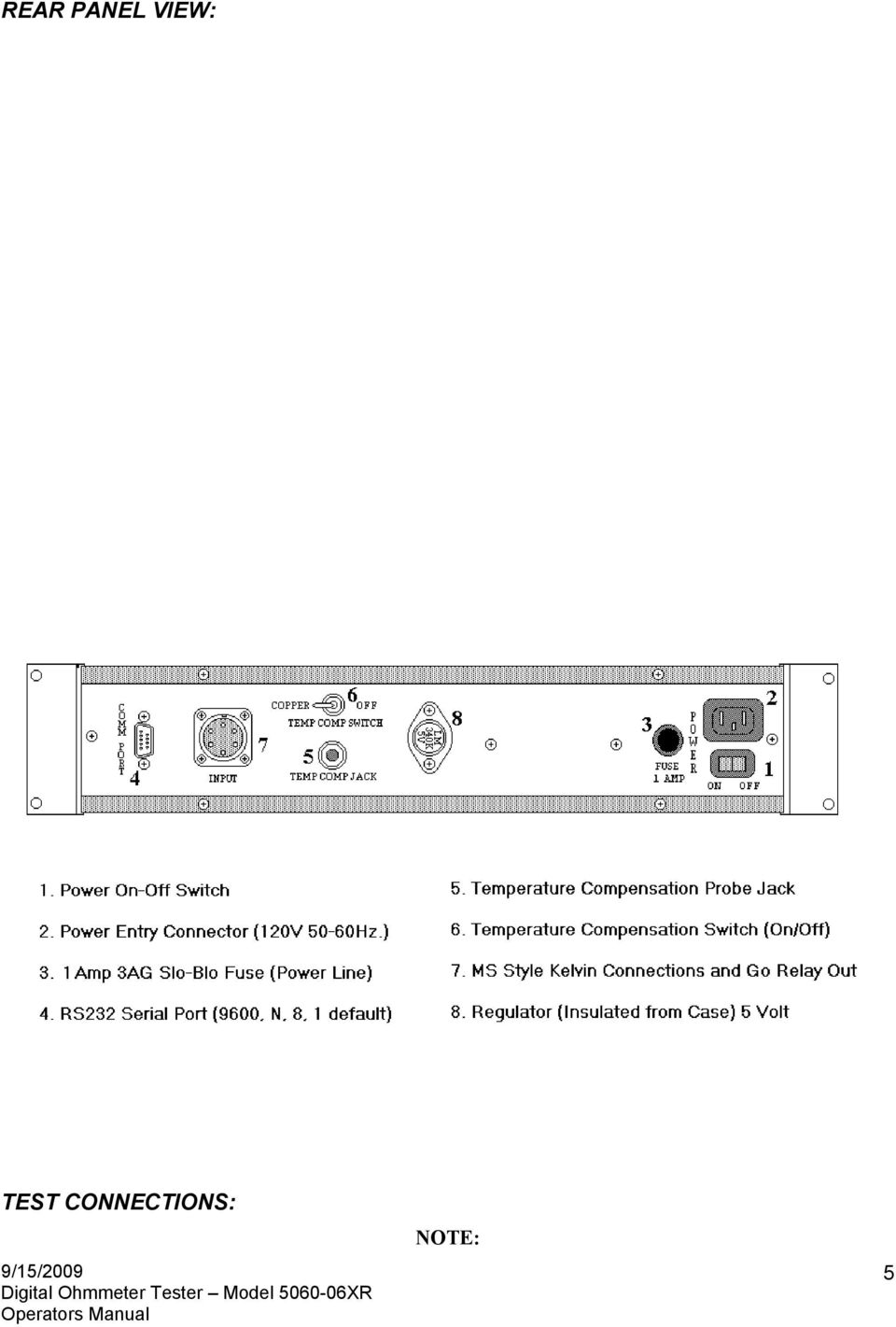
6 For greatest accuracy each voltage and current lead must connect separately to the component under test. This is most critical in low resistance measurements. I + V + FRONT PANEL BANANA JACKS UNKNOWN RESISTANCE I - V - B F E A C I + v + v - I - UNKNOWN RESISTANCE D REAR PANEL CIRCULAR CONNECTOR N. O. RELAY CLOSED FOR GOOD PART XP CALIBRATION PROCEDURE REQUIRED EQUIPMENT: A digital voltmeter with a 4½ digit resolution and a 200 millivolt full scale range is required. You will need a set of six standard resistances, one for each range to be calibrated. A precision of at least 0.02% is necessary to calibrate this instrument to specifications. Harris IRT Enterprises can supply a 0.02% resistance set, Model 2005, with standard resistances and switchable Kelvin connections. Recommended standard resistance Milliohms ( Ohms) Milliohms 6

7 Milliohms Ohms (1.99K Milliohms) Ohms Ohms NOTE: The resistances must be just below the full scale value of each range. It is important to check the instrument calibration before attempting any adjustments. The Calibration check procedure is listed below. A suitable set of 4-wire Kelvin test leads will be required for connecting the standard resistances to the instrument. Either the front panel jacks or the rear panel MS- Style connector may be used for the Kelvin test leads. Calibration Check: Turn Power On to the instrument and allow a five minute warm-up time before checking calibration. Be certain that temperature compensation switch is turned to the OFF position while checking calibration or adjusting calibration. Check each range using a certified standard value near full scale for the range being checked. All readings must be within 2 counts of the certified value near full scale. Next check all ranges at 10% of full scale using the certified standard for the next lower range. Again the readings must be within 2 counts of the certified value. Note that 1 additional digit of dither is permitted by the specifications. If the instrument meets these specifications on all ranges, do not perform a calibration procedure. You will eventually wear out the adjustment potentiometers. If all of the ranges require major adjustment, there is likely a component failure or some problem in the test setup. Caution: Never select the 2 Milliohm Range with any standard but the 1.99 Milliohm connected to the The 1 Amp current can easily damage the other standard resistors. Calibration Procedure: Note: Adjustment locations are shown on the next page. 1. Connect the Kelvin Test leads as follows: Tightly twist and solder together the four wires from the E+, E-, and I- terminals. Select the 0.2-Milliohm range Since the Chopper Stabilized Preamp automatically zeros between readings, the display should read close to Milliohms. It is however, very difficult to make a true zero Ohm connection. 2. Connect a Ohm standard to the four wire Kelvin test leads and select the 200K Milliohm range. Connect a 4 ½-Digit voltmeter across the standard resistor and adjust the potentiometer marked I x 1 until a voltage of V is indicated on the voltmeter. You may also adjust the potentiometer marked 100μA if more range is needed. With the external voltmeter removed, the 5060 display should be within a percent or so of the correct reading at this point. The I x 1 control can be used to bring the ohmmeter reading to the exact value of the standard resistor used 3. Connect the Ohm standard and select the 20K-Milliohmhm Range. Adjust the E x 10 control until the certified value is displayed on the Ohmmeter. 4. Connect the Ohm standard resistor and select the 2K-Milliohm range. Adjust the control marked 1 ma until the Ohmmeter display indicates the certified value of this standard. 5. Connect the Ohm standard resistor to the Kelvin test leads and select the 200-Milliohm range. Adjust the 10 ma potentiometer until the certified value is displayed. 7

8 6. Connect the Milliohm standard and select the 20 Milliohm range. Adjust the 100 ma potentiometer until the proper resistance value is displayed 7. Connect the Milliohm ( Ohm) standard and select the 2.0 Milliohm range. Adjust the 1000 ma potentiometer until the Display indicates the certified resistance value. 8. Perform a complete calibration check as described at the beginning of this procedure. Your calibration should now be within factory specifications. An annual calibration check is recommended to keep your instrument within specifications XR Component and Adjustment Locations: OPTIONS TEMPERATURE COMPENSATION ( TC ): Temperature changes of a few degrees in a product can have significant effects on the product s resistance. Therefore, the need for temperature compensation may arise when the temperature of the part being tested changes over a period of time. The benefits of temperature compensation include the saving of time, energy, and money by eliminating the need to refer to coefficient tables as the ambient plant temperature varies during the day. Before now, such compensation was available only in expensive and delicate laboratory-grade instruments. Harris IRT has now made it available in rugged resistance testers designed for use in production. 8

9 With temperature compensation, a probe sends ambient temperature data to the instrument. This temperature information is used to modify the constant current that is being passed through the part under test. The resistance then registered is the resistance the item under test would have at the specified temperature. The compensation option can be calibrated for the measurement of either of two measurement coefficients or it can be operated without any compensation. The accuracy of the compensation is within 0.2 % of the actual resistance between 0 and 50 C. BINARY CODED DECIMAL ( BCD ): BCD is not available on the portable XP Series Ohmmeters. It is available in the Rack Mount XR series cases. The BCD output allows the resistance tester to transmit readings to a Programmable Logic Controller (PLC). The BCD option generates a 1, 2, 4, and 8 bit for each of the 5 characters in the resistance reading. An output strobe is also provided to allow synchronization of the resistance tester with the PLC. The BCD output is a TTL logic level of 0 to 5 VDC and a maximum output current of 24 ma. REMOTE RANGE SELECT ( RR ): The remote range select option is typically used in on-line testing when various resistances must be tested. This option allows a PLC or other controller on the production line to set the range of the resistance tester. This option is usually used in conjunction with the BCD or RS-232 options. In the new X-series of the IRT Testers the remote range selection is done through the RS-232 serial port. The serial port can also be used to externally set upper and lower limit sensors. This feature is most useful with the Test Channel Multiplex Option. SAMPLE and HOLD ( SH ): This option is available only in the Rack Mount XR series ohmmeters because of space restrictions. It permits the measurement of a component s resistance on-the-fly even though the contact time with the component is very brief (a few milliseconds). It is possible to hold a resistance reading for digital processing and display. 100 % testing is possible under such conditions. SAFETY RELAY ( RY ): When a resistance tester is used in conjunction with high pot or surge tests, an internal safety relay can be provided to lock-out the resistance tester circuitry during other testing. This will protect the resistance tester from possible high-voltage or high-current damage. Due to space requirements, this is only available in the Rack Mount cases. RS-232 COMPUTER INTERFACE ( RS232 ): A three-wire link between the resistance tester and a computer can be made through the RS-232 port. This is a standard null-modem connection with a 9600-Baud rate, and a word length of 8 bits. The default Baud rate is set to 9600 at the factory. This permits the reading shown on the front panel display to be sent to an external computer or PLC, every time the instrument receives an ASCII from the host. This interface is useful for the statistical analysis of production, predictive control, and data logging. It is compatible with any computer or PLC having an RS-232 port. Factory settings for the Serial Port: 9600 Baud, No stop bit, 8 bit word, No parity. (9600,N,8,1) Program changes can permit operation up to 56K Baud on special order. 9

10 NULL MODEM CONNECTIONS: The RS-232 port is usually interfaced to a computer using terminal software and responds much like a dumb terminal. For the connecting cable use a MALE DB-9 style connector wired with the following pin configuration. Function Receive ( Rx ) Pin 2 Common ( Com ) Pin 5 Transmit ( Tx ) Pin 3 Connector Pin Whenever the host computer sends any character to the RS-232 port, it will respond by returning the 5 characters plus the decimal shown in the display of the resistance tester. In the case of the Model X- Series resistance tester, which has only a four-digit display, a six-digit character group is still sent. The fifth digit is the least significant digit. After the five-character resistance reading is sent including the decimal point, the port will stand by, waiting to receive the next character from the computer before returning the current reading. NOTE: The resistance tester does not send Start Of Text (0X02 Hex), End Of Text (0X03 Hex) or a Carriage Return (0X0D Hex). The unit simply stops sending data after the 5th digit. Special ASCII characters can be appended on a custom basis. 10

11 TEMPERATURE COMPENSATION PROCEDURE PRE-CALIBRATION PROCEDURE: Plug the Temperature Compensation Probe into the jack located on the rear panel. Make a coil of copper wire, approximately one Ohm in resistance, that will easily fit into your water bath containers. Make up a 4- wire Kelvin connection to the Standard coil and connect the 4 wires to the test jacks on the front panel of your Ohmmeter. Using a Voltmeter, measure the voltage between the green and gray wires on the stereo jack located on the rear panel. The measured reading should be approximately 2.73 Volts +10 mv per C. For example, the room temperature is 25 C. The voltage reading should be about 2.98 Volts. If the voltage reading is more than ±20 mv from the calculated reading or the reading is 12 V, then the TC probe is defective. Replacement TC probes can be ordered from Harris IRT Enterprises as part # -TCP. Note: TC probes are not interchangeable without re-calibration. Each Probe must be calibrated to work with its own IRT Unit. PREPARING THE WATER BATHS: Three water baths will be needed for proper calibration: One bath at the specified STANDARD temperature; a HOT bath at +20 C from the specified temperature and a COLD bath at -20 C from the specified temperature. For example, if the specified temperature is 25 C, using a Celsius thermometer prepare one bath for 25 C, a HOT bath at 45 C and a COLD bath (using ice cubes if necessary) at 5 C. It is important that enough water is used in each bath so that room temperature will not effect the temperatures of the baths before the calibration is complete. Also make sure that the STANDARD bath is EXACTLY what the standard temperature should be. Location of Temp. Comp. Adjustments CALIBRATION PROCEDURE: 1) Plug the temperature compensation probe into the rear of the resistance tester. Connect the 1- Ohm Standard coil to either the MS-connector or the Front Panel Test terminals using a 4-wire Kelvin connection. 2) Set the resistance tester to the 2-Ohm range. Make sure the temperature compensation switch located on the rear panel is in the OFF (center) position. 11

12 3) Place the TC probe and the resistance standard into the specified temperature bath. Stir the TC probe and the resistance standard a few times until the readings stabilize. After the display stabilizes (usually a few minutes) record the coil resistance reading. Step #3 Reading 4) Switch the temperature compensation switch to the ON position. 5) Adjust the TZ Potentiometer until the display reads the same as the recorded reading in Step #3. Place the TC probe and the resistance standard into the HOT bath. Stir the TC probe and the resistance standard a few times until the display stabilizes (usually a few minutes), adjust POT TA until the display reads the same as the recorded reading in Step #3. 6) Place the TC probe and the one Ohm standard coil into the COLD bath. Stir the TC probe and the coil standard a few times until the display stabilizes. Step #6 Reading 7) Subtract the reading from Step #6 from the recorded reading in Step #3. Divide the ANSWER by 2. Add this result to the original reading in Step #7, and record the result. Step #3 reading Step #6 reading Answer/2 = + Step #6 + Answer = Step #8 result 8) Adjust potentiometer TA until the display reads the same as the recorded result in Step #8 9) Turn the temperature compensation switch to the OFF position. The temperature compensation procedure is completed. 12
, adjust POT TA until the display reads the same as the recorded reading in Step #3.")
13 TROUBLE-SHOOTING HINTS SYMPTOM: The Resistance Testers display flashes POSSIBLE SOLUTIONS: The Resistance Tester is in over-range mode, select a higher range. The ICL7135 CPI A/D converter could be burned-out. This IC is socketed and can easily be replaced by the user 1. SYMPTOM: The Resistance Tester displays changing numbers or garbage readings. POSSIBLE SOLUTIONS: Check to make sure a load is connected to the Resistance Tester via the back panel circular connector or front panel banana plugs. While the Kelvin Connection is open circuit (I+ not connected to E+ and I_ not connected to E-) the voltage present on the Voltage input terminals will be random. Because there is a small capacitor on the input circuit, you will display any static charge that has accumulated on this capacitor. This is the normal behavior of a Kelvin input instrument. Check to make sure you have a valid 4 wire Kelvin connection. (see illustration below) SYMPTOM: Readings all appear to be incorrect. POSSIBLE SOLUTIONS: Check to see if the Temperature Compensation switch is in the proper position and that the TC probe is completely inserted into the rear panel Jack. Is the Resistance Tester is due for calibration? A calibration should be performed once a year. 1 Opening the meter to replace any IC s could void the manufacturers warranty.
 the voltage present on the Voltage input terminals will be random.")
14 Insure that the front panel I and E terminals are not connected to permit a 2-wire non-kelvin test. Although the meter accuracy will be OK on the higher ranges, this will cause severe errors on the lower resistance ranges. This will be a problem even if you are using the MS-Style connector for you Kelvin Leads. Using the 4-wire test leads but connecting them to only two pogo pins will leave the pogo pin resistance and the contact resistance in the measurement. Four individual connections must be made to the test component s terminals to get a real Kelvin connection. One or more of the OP177 op-amps could be burned-out. These IC s are socketed and can easily be replaced by the user 1. Check to make sure you have a true 4-wire Kelvin connection. NOTE: Resistance changes as temperature changes. If the ambient temperature varies during the day so will the resistance of the part under test. This could make it appear that the Resistance Tester is not working properly. You may require the use of Temperature Compensation. For Technical assistance call Harris IRT Enterprises at (740) RETURN POLICY NOTE: Before returning a Resistance Tester for repair or calibration you must first call and receive an RMA#. Any package received without an RMA# will be returned to shipper. Please write the RMA# on the package and packing slip. To return a Resistance Tester for repair after you receive an RMA# ship to: MANUFACTURER S WARRANTY Harris IRT Enterprises 155 Johnson Dr. Delaware, Ohio Phone: (740) Fax: (740) Equipment shall meet all engineering performance data and design requirements described in the specifications. Within a period of one year from the date of shipment, if the equipment should fail to function due to a defect in parts or workmanship, Harris IRT Enterprises, at its option, will replace or repair the equipment at its facility in Delaware, Ohio. NOTE: Removing the calibration seal and performing unauthorized repairs will void the calibration and could void the manufacturers warranty. Please call Harris IRT Enterprises before performing any repairs. 14

15 MODEL XR MAIN PCB ASSEMBLY DRAWING 5012X-Series Display Board 15

LDG DTS-4/4R Desktop Coaxial Switch / Remote
 LDG DTS-4/4R Desktop Coaxial Switch / Remote LDG Electronics 1445 Parran Road, PO Box 48 St. Leonard MD 20685-2903 USA Phone: 410-586-2177 Fax: 410-586-8475 ldg@ldgelectronics.com www.ldgelectronics.com
CONTENTS. PAGE Chapter 1 General Information 1. Chapter 2 Setup 4 DP450-VDC 7 DP450-VAC 7 DP450-DCC 7 DP450-F 8 DP450-HACC 9 DP450-HDCC 11 DP450-E 13
 CONTENTS PAGE Chapter 1 General Information 1 Chapter 2 Setup 4 DP450-VDC 7 DP450-VAC 7 DP450-DCC 7 DP450-F 8 DP450-HACC 9 DP450-HDCC 11 DP450-E 13 Chapter 3 Alarm/Excitation Options 15 Wiring 17 Chapter
RS232C < - > RS485 CONVERTER S MANUAL. Model: LD15U. Phone: 91-79-4002 4896 / 97 / 98 (M) 0-98253-50221 www.interfaceproducts.info
 0-98253-50221 www.interfaceproducts.info") RS232C < - > RS485 CONVERTER S MANUAL Model: LD15U INTRODUCTION Milestone s model LD-15U is a RS232 to RS 485 converter is designed for highspeed data transmission between computer system and or peripherals
RS232C < - > RS485 CONVERTER S MANUAL Model: LD15U INTRODUCTION Milestone s model LD-15U is a RS232 to RS 485 converter is designed for highspeed data transmission between computer system and or peripherals
MODEL 5010 DUAL CHANNEL SMOKE/FIRE DETECTION MODULE
 DESCRIPTION MODEL 5010 DUAL CHANNEL SMOKE/FIRE DETECTION MODULE DESCRIPTION The SST Model 5010 Two Channel Smoke/Fire Detection Module provides two independent detection input channels for the NOVA-5000
Technical Manual. For use with Caller ID signaling types: Belcore 202, British Telecom, & ETSI
 Technical Manual For use with Caller ID signaling types: Belcore 202, British Telecom, & ETSI Caller ID.com WHOZZ CALLING? POS 2 Caller ID Monitoring Unit Technical Manual For use with Caller ID signaling
TCP/IP MODULE CA-ETHR-A INSTALLATION MANUAL
 TCP/IP MODULE CA-ETHR-A INSTALLATION MANUAL w w w. c d v g r o u p. c o m CA-ETHR-A: TCP/IP Module Installation Manual Page Table of Contents Introduction...5 Hardware Components... 6 Technical Specifications...
IRT Eurocard. Type DAX-3206. Audio Extractor for 270 Mb/s SDI
 I R T Electronics Pty Ltd A.B.N. 35 000 832 575 26 Hotham Parade, ARTARMON N.S.W. 2064 AUSTRALIA National: Phone: (02) 9439 3744 Fax: (02) 9439 7439 International: 61 2 9439 3744 61 2 9439 7439 Email:
DPI 260 SERIES: Digital Pressure Indicators
 DPI 260 SERIES: Digital Pressure Indicators INTRODUCTION The DPI 260, 261 and 262 range of digital pressure instruments measure and indicate pressure in any specified scale units and provide accuracies
DISCONTINUED. AtlasScientific. as of 10/21/13. E.C. Circuit. Biology Technology. Features
 DISCONTINUED as of 10/21/13 E.C. Circuit V 3.0 Features E.C. readings +/- 5µs/cm Full E.C. capability from 11µs/cm to 92,000µs/cm Temperature dependent or temperature independent readings Total dissolved
OPERATING INSTRUCTIONS Model ST-888 DTMF ANI/ENI Display Decoder
 P R O D U C T G R O U P OPERATING INSTRUCTIONS Model ST-888 DTMF ANI/ENI Display Decoder Manual # 600-0901 November 30, 1999 Rev. D - 99068 DESCRIPTION The ST-888 Mobilecall Display Decoder is a desktop
F2400 FOM II Series Fiber Optic Modem Technical Manual
 F2400 FOM II Series Fiber Optic Modem Technical Manual T1 Revision B Copyright April 2003 VERSITRON, Inc. 83 Albe Drive / Suite C Newark, DE 19702 www.versitron.com A030430283T PROPRIETARY DATA All data
Product Information Sheet UH28CS-12kV Hi Pot Tester
 Product Information Sheet UH28CS-12kV ETL Prüftechnik GmbH Telefon: +49 711 83 99 39-0 E-Mail: info@etl-prueftechnik.de Carl-Peters-Straße 23 D-70825 Korntal-Münchingen Telefax: +49 711 83 99 39-9 Internet:
CONNECTOR AMPLIFIER FOR PROPORTIONAL VALVES (4-20 ma Input Version)
") TECHNICAL DATASHEET #TD1102AX CONNECTOR AMPLIFIER FOR PROPORTIONAL VALVES (4-20 ma Input Version) Part Number: Connector Amplifier CAPV-H-4-20MA-x complete with cable CAPV-4C-yM Where: x = current output
TECHNICAL DATASHEET #TD1102AX CONNECTOR AMPLIFIER FOR PROPORTIONAL VALVES (4-20 ma Input Version) Part Number: Connector Amplifier CAPV-H-4-20MA-x complete with cable CAPV-4C-yM Where: x = current output
LDG DTS-6/6R Desktop Coaxial Switch / Remote
 LDG DTS-6/6R Desktop Coaxial Switch / Remote LDG Electronics 1445 Parran Road, PO Box 48 St. Leonard MD 20685-2903 USA Phone: 410-586-2177 Fax: 410-586-8475 ldg@ldgelectronics.com www.ldgelectronics.com
Troubleshooting Tips Lifestyle SA-2 & SA-3 Amplifier. Troubleshooting Tips
 Troubleshooting Tips Lifestyle SA-2 & SA-3 Amplifier Refer to the Lifestyle SA-2 & SA-3 Amplifier service manuals, part number 271720 for schematics, PCB layouts and parts lists. Preventative Repair Measures
STATE OF NEW JERSEY DEPARTMENT OF TRANSPORTATION TRENTON, NEW JERSEY 08625 METRIC SPECIFICATIONS FOR RS232 LEASED LINE MODEMS (LOW SPEED MODEL 400)
") STATE OF NEW JERSEY DEPARTMENT OF TRANSPORTATION TRENTON, NEW JERSEY 08625 METRIC SPECIFICATIONS FOR RS232 LEASED LINE MODEMS (LOW SPEED MODEL 400) N.J. Specification No. Effective Date: July 1, 2001 New
STATE OF NEW JERSEY DEPARTMENT OF TRANSPORTATION TRENTON, NEW JERSEY 08625 METRIC SPECIFICATIONS FOR RS232 LEASED LINE MODEMS (LOW SPEED MODEL 400) N.J. Specification No. Effective Date: July 1, 2001 New
Digital and Analog I/O
 70072-0127-07 TECHNICAL NOTE 02/2007 Digital and Analog I/O This document discusses the application and configuration of digital and analog inputs/outputs (I/O). Details are for both onboard I/O and external
MANUAL PC1000R INFO@APART-AUDIO.COM
 MANUAL PC1000R INFO@APART-AUDIO.COM Features The APart PC1000R is a professional multisource CD/USB/SD card music player, equipped with balanced and unbalanced analog outputs, coaxial and optical digital
HCS-3300/3302/3304 USB Remote Programmable Laboratory Grade Switching Mode Power Supply
 1. INTRODUCTION HCS-3300/3302/3304 USB Remote Programmable Laboratory Grade Switching Mode Power Supply User Manual This family of efficient, upgraded SMPS with small form factor, auto cross over CV CC,
3½ DIGIT VOLTMETER MODULE LED- / LCD- SERIES
 12.02 EA 4035-SERIES 3½ DIGIT VOLTMETER MODULE LED- / LCD- SERIES Splashproof 35,1x22,4 mm FEATURES * IP65 * 2 LED AND 2 LCD TYPES * EASY TO USE OR COMPATIBLE TO DATEL * ±200mV D.C. FULL SCALE READING
Instruction Manual RCI-800-XXX. Remote Control Signal Interface
 Manufacturers of Process Controls and Instrumentation Instruction Manual Model: Function: Communication: Input: Output: Power: RCI-800-XXX Remote Control Signal Interface XXX=SER: RS-232/485 XXX=MDM Modem
User's Guide. Integrating Sound Level Datalogger. Model 407780. Introduction
 User's Guide 99 Washington Street Melrose, MA 02176 Phone 781-665-1400 Toll Free 1-800-517-8431 Visit us at www.testequipmentdepot.com Back to the Extech 407780 Product Page Integrating Sound Level Datalogger
IPX AUTOMATIC IP NETWORK LOSS BACKUP A/B SWITCH INSTRUCTION BOOK IB6444-02
 IPX AUTOMATIC IP NETWORK LOSS BACKUP A/B SWITCH INSTRUCTION BOOK IB6444-02 TABLE OF CONTENTS DESCRIPTION 2 MOUNTING INSTRUCTIONS 2 HOW TO CABLE THE IPX 2/3 POWER SUPPLY INSTALLATION 3 OPERATION 3 CARE
Essential Electrical Concepts
 Essential Electrical Concepts Introduction Modern vehicles incorporate many electrical and electronic components and systems: Audio Lights Navigation Engine control Transmission control Braking and traction
JNIOR. Overview. Get Connected. Get Results. JNIOR Model 310. JNIOR Model 312. JNIOR Model 314. JNIOR Model 410
 The INTEG is an Ethernet I/O (digital, analog) device that monitors and controls a small set of process signals. functions as both basic I/O for integration with another application or system AND as a
THERMAL ANEMOMETRY ELECTRONICS, SOFTWARE AND ACCESSORIES
 TSI and TSI logo are registered trademarks of TSI Incorporated. SmartTune is a trademark of TSI Incorporated. THERMAL ANEMOMETRY ELECTRONICS, SOFTWARE AND ACCESSORIES IFA 300 Constant Temperature Anemometry
IO-DIM6 6-Channel, Digital to Analogue Converters
 Page 1 of 6 IO-DIM6 6-Channel, Digital to Analogue Converters Features: Benefits: Input status indication Calibrated output DIN Rail mounting Expands controller input capacity Fault finding LED indication
Conversion Between Analog and Digital Signals
 ELET 3156 DL - Laboratory #6 Conversion Between Analog and Digital Signals There is no pre-lab work required for this experiment. However, be sure to read through the assignment completely prior to starting
Temperature & Humidity SMS Alert Controller
 Temperature & Humidity Alert Controller METERS 3 simple steps starting the unit: Insert the SIM card Plug in the sensors connectors Connect the AC power cord. Specifications: AC 90~260V Auto Select Internal
NSI DIGITAL DIMMING SYSTEM DDS 9800 DIMMER PACKS
 NSI DIGITAL DIMMING SYSTEM NSI DIGITAL DIMMING SYSTEM DDS 9800 DIMMER PACKS Software Revision 1.41, Version C UL, Mfg Q3/96, and above SPECIFICATIONS Number of Channels: 9800 : 8 channels Output capacity:
User Manual. Humidity-Temperature Chart Recorder. Model RH520
 User Manual Humidity-Temperature Chart Recorder Model RH520 Introduction Congratulations on your purchase of the Extech RH520 Temperature + Humidity Chart Recorder. The RH520 measures and displays Temperature,
Sierra S-Series Smart Interface Software User Manual
 Sierra S-Series Smart Interface Software User Manual Part Number IM-SIP 08/99 Revision B 5 Harris Court, Building L Monterey, CA 93940 (831) 373-0200 (800) 866-0200 Fax (831) 373-4402 http://www.sierrainstruments.com
BROOKFIELD MODEL VTE250 ELECTRIC VISCOSEL PROCESS VISCOMETER. Installation, Operation, and Maintenance Instructions. Manual No.
 BROOKFIELD MODEL VTE250 ELECTRIC VISCOSEL PROCESS VISCOMETER Installation, Operation, and Maintenance Instructions Manual No. M06-512 SPECIALISTS IN THE MEASUREMENT AND CONTROL OF VISCOSITY BROOKFIELD
Low Cost, Precision IC Temperature Transducer AD592*
 a FEATURES High Precalibrated Accuracy:.5 C max @ +25 C Excellent Linearity:.15 C max ( C to +7 C) Wide Operating Temperature Range: 25 C to +15 C Single Supply Operation: +4 V to +3 V Excellent Repeatability
Physical Specifications (Custom design available.)
") Helmholtz Coils A useful laboratory technique for getting a fairly uniform magnetic field, is to use a pair of circular coils on a common axis with equal currents flowing in the same sense. For a given
Helmholtz Coils A useful laboratory technique for getting a fairly uniform magnetic field, is to use a pair of circular coils on a common axis with equal currents flowing in the same sense. For a given
Kit 106. 50 Watt Audio Amplifier
 Kit 106 50 Watt Audio Amplifier T his kit is based on an amazing IC amplifier module from ST Electronics, the TDA7294 It is intended for use as a high quality audio class AB amplifier in hi-fi applications
SYSTEM 4C. C R H Electronics Design
 SYSTEM 4C C R H Electronics Design SYSTEM 4C All in one modular 4 axis CNC drive board By C R Harding Specifications Main PCB & Input PCB Available with up to 4 Axis X, Y, Z, A outputs. Independent 25
1993 ACCESSORIES & EQUIPMENT Volkswagen Instrument Panels. Volkswagen; EuroVan, Passat
 Article Text Saturday, March 18, 2000 10:33PM ARTICLE BEGINNING 1993 ACCESSORIES & EQUIPMENT Volkswagen Instrument Panels Volkswagen; EuroVan, Passat DESCRIPTION & OPERATION Instrument cluster for most
************* OWNER'S MANUAL BAMF800/2 BAMF1250/2 BAMF1800/2 BAMF2200/2 BAMF2600/2 BAMF1200/4 BAMF1600/4 BAMF2000/1D BAMF4000/1D BAMF5500/1D
 ************* OWNER'S MANUAL BAMF800/2 BAMF1250/2 BAMF1800/2 BAMF2200/2 BAMF2600/2 BAMF1200/4 BAMF1600/4 BAMF2000/1D BAMF4000/1D BAMF5500/1D INTRODUCTION Power Acoustik amplifiers provide high-performance
INSTRUCTION MANUAL for UNIBLITZ MODEL DM412 SHUTTER DRIVE MODULE
 INSTRUCTION MANUAL for UNIBLITZ MODEL DM412 SHUTTER DRIVE MODULE VINCENT ASSOCIATES 803 LINDEN AVE. ROCHESTER, NEW YORK 14625 SERVICE/ORDERS (800) 828-6972 In NY State (585) 385-5930 Fax (585) 385-6004
Dielectric Withstand and Ground Bond Testers For Production Line Safety Agency Compliance Testing
 Dielectric Withstand and Ground Bond Testers For Production Line Safety Agency Compliance Testing U.S. patent#: 5,548,501, 6,054,865. Other patents pending. Safety agency listed. ENHANCED GRAPHIC LCD The
IRT Eurocard. Types DAX-3200
 I R T Electronics Pty Ltd A.B.N. 35 000 832 575 26 Hotham Parade, ARTARMON N.S.W. 2064 AUSTRALIA National: Phone: (02) 9489 3744 Fax: (02) 9439 7439 International: +61 2 9439 3744 +61 2 9439 7439 Email:
Instruction Manual. This manual covers models: 8-125E 60-18E 20-50E 80-13E 33-33E 150-7E 40-25E 300-3.5E 50-20E 600-1.7E
 DCS-E SERIES POWER SUPPLIES Instruction Manual This manual covers models: 8-125E 60-18E 20-50E 80-13E 33-33E 150-7E 40-25E 300-3.5E 50-20E 600-1.7E SORENSEN Division of Elgar 9250 Brown Deer Road San Diego,
TC-9102 Series Surface Mount Temperature Controllers
 TC-9102 Series Surface Mount Temperature Controllers General Description & Applications The TC-9102 Series Temperature Controller offers a versatile solution for a wide variety of applications that may
RDF1. RF Receiver Decoder. Features. Applications. Description. Ordering Information. Part Number Description Packages available
 RDF1 RF Receiver Decoder Features Complete FM Receiver and Decoder. Small Form Factor Range up to 200 Metres* Easy Learn Transmitter Feature. Learns 40 transmitter Switches 4 Digital and 1 Serial Data
Model 5511 Filler Controller User s Manual Version 1.1 October 2011
 Thompson Scale Company WEIGHING SYSTEMS & PACKAGING MACHINERY CONTROLS 2758 Bingle Road Houston, Texas 77055 Phone: 713/932-9071 Fax: 713/932-9379 www.thompsonscale.com Model 5511 Filler Controller User
Automation System TROVIS 6400 TROVIS 6493 Compact Controller
 Automation System TROVIS 6400 TROVIS 6493 Compact Controller For panel mounting (front frame 48 x 96 mm/1.89 x 3.78 inch) Application Digital controller to automate industrial and process plants for general
PERF10 Rubidium Atomic Clock
 Owner s Manual Audio Stanford Research Systems Revision 1.0 February, 2011 2 Certification Stanford Research Systems certifies that this product met its published specifications at the time of shipment.
Research RF Sputtering Packages
 Research RF Sputtering Packages Shown with 3" Polaris Adjustable Position Source with Tilt and Shutter 300 or 600 Watt Low Cost Packages for Those With Limited Budgets Desiring Full Capability 13.56 MHz
AutoRanging Digital MultiMeter
 Owner's Manual AutoRanging Digital MultiMeter Model No. 82139 CAUTION: Read, understand and follow Safety Rules and Operating Instructions in this manual before using this product. Safety Operation Maintenance
Dashboard Digital Voltmeter
 Dashboard Digital Voltmeter...November, 2002 This project is helpful to anyone who drives an automobile. I had found this project at the local libary... in an old publication. I made it and it worked fine.
1. SAFETY INFORMATION
 RS-232 Sound Level Meter 72-860A INSTRUCTION MANUAL www.tenma.com 1. SAFETY INFORMATION Read the following safety information carefully before attempting to operate or service the meter. Use the meter
Manual Ranging MultiMeter
 Owner s Manual Manual Ranging MultiMeter Model 82345 CAUTION: Read, understand and follow Safety Rules and Operating Instructions in this manual before using this product.! Safety! Operation! Maintenance!
Model SRMD Setra Remote Monitoring Display
 Model SRMD Setra Remote Monitoring Display 1.0 GENERAL INFORMATION Thank you for purchasing the Setra Remote Monitoring Display (SRMD). The SRMD is a digital panel meter with a bright 1 LED display for
ENET-710. ENET-710 - Ethernet Module ENET-710 JAN / 06 FOUNDATION
 ENET-710 ENET-710 - Ethernet Module JAN / 06 ENET-710 FOUNDATION E N E T 7 1 0 ME smar www.smar.com Specifications and information are subject to change without notice. Up-to-date address information is
Polyphase kwh Electricity Meter
 Polyphase kwh Electricity Meter Model Type: 5192B USER MANUAL Issue 1.0 E & O E AMPY Automation Ltd. July 2003 doc. ref. CSD 093 Contents 1 Introduction 2 1.1 Purpose 2 2 Definitions 2 2.1 References 2
INSTALLATION & SERVICE MANUAL. Display Panel
 INSTALLATION & SERVICE MANUAL Display Panel The PowerLine EMS TM is a specialized power distribution and energy management system intended to be used in recreational vehicles. The Control Module is housed
Using Thermocouple Sensors Connecting Grounded and Floating Thermocouples
 Connecting Grounded and Floating Thermocouples For best performance, Thermocouple sensors should be floating. This will ensure that no noise currents can flow in the sensor leads and that no common-mode
RS-232 Communications Using BobCAD-CAM. RS-232 Introduction
 RS-232 Introduction Rs-232 is a method used for transferring programs to and from the CNC machine controller using a serial cable. BobCAD-CAM includes software for both sending and receiving and running
C220 PRELIMINARY TUBE PREAMPLIFIER SERVICE MANUAL. SERIAL NO. WS1001 And Above C220. Serial Number W S1001 And Above CONTENTS
 Performance Specifications... 2 Notes... 2 Rear Panel... 3 Section Location... 3 Block Diagram... 5-6 Interconnection Diagram... 7-8 Main Schematic and PCB... 9-18 C220 TUBE PREAMPLIFIER CONTENTS Display
OWNERS MANUAL. WattsVIEW. Power Monitor Model: DC-10000. http://wattsview.com. WattsVIEWTM. Models: DC-10000 Serial DC-1000 USB DC-25000
 WattsVIEW Power Monitor Model: DC-10000 DC Power Monitoring Made Easy Models: DC-10000 Serial DC-1000 USB DC-25000 OWNERS MANUAL PAGE 1 of 23 Table of Contents WattsVIEW Power Monitor Model: DC-10000...1
FMA 3100/3100ST/3300/3300ST Series Thermal Mass Flow Sensors and Meters
 FMA 3100/3100ST/3300/3300ST Series Thermal Mass Flow Sensors and Meters M-4270/0707, pg. 2 of 29 READ THIS MANUAL COMPLETELY BEFORE ATTEMPTING TO CONNECT OR OPERATE YOUR FLOW SENSOR. FAILURE TO DO SO MAY
Modular I/O System Analog and Digital Interface Modules
 OPERATING INSTRUCTIONS Modular I/O System Analog and Digital Interface Modules Installation Operation Maintenance Document Information Document ID Title: Operating Instructions Modular I/O System Part
M68EVB908QL4 Development Board for Motorola MC68HC908QL4
 M68EVB908QL4 Development Board for Motorola MC68HC908QL4! Axiom Manufacturing 2813 Industrial Lane Garland, TX 75041 Email: Sales@axman.com Web: http://www.axman.com! CONTENTS CAUTIONARY NOTES...3 TERMINOLOGY...3
RI-215A Operator s Manual. Part Number: 71-0045RK Revision 0 Released: 10/3/05
 RI-215A Operator s Manual Part Number: 71-0045RK Revision 0 Released: 10/3/05 Warranty RKI Instruments, Inc., warrants gas alarm equipment sold by us to be free from defects in materials and workmanship,
Advantium 2 Plus Alarm
 ADI 9510-B Advantium 2 Plus Alarm INSTALLATION AND OPERATING INSTRUCTIONS Carefully Read These Instructions Before Operating Carefully Read These Controls Corporation of America 1501 Harpers Road Virginia
User Guide. Temperature and Humidity Datalogger. Model 42280
 User Guide Temperature and Humidity Datalogger Model 42280 Introduction Congratulations on your purchase of the Extech 42280 Thermometer and Relative Humidity Datalogger. The 42280 is a wall-mount, tripod
AIR QUALITY SURVEILLANCE BRANCH ACCEPTANCE TEST PROCEDURE (ATP) FOR. Teledyne Advanced Pollution Instruments Model 400 E Ozone Analyzer AQSB ATP 002
 FOR. Teledyne Advanced Pollution Instruments Model 400 E Ozone Analyzer AQSB ATP 002") AIR QUALITY SURVEILLANCE BRANCH ACCEPTANCE TEST PROCEDURE (ATP) FOR Teledyne Advanced Pollution Instruments Model 400 E Ozone Analyzer AQSB ATP 002 First Edition MONITORING AND LABORATORY DIVISION August
AIR QUALITY SURVEILLANCE BRANCH ACCEPTANCE TEST PROCEDURE (ATP) FOR Teledyne Advanced Pollution Instruments Model 400 E Ozone Analyzer AQSB ATP 002 First Edition MONITORING AND LABORATORY DIVISION August
Digital I/O: OUTPUT: Basic, Count, Count+, Smart+
 Digital I/O: OUTPUT: Basic, Count, Count+, Smart+ The digital I/O option port in the 4-Series provides us with 4 optically isolated inputs and 4 optically isolated outputs. All power is supplied externally.
Isolated AC Sine Wave Input 3B42 / 3B43 / 3B44 FEATURES APPLICATIONS PRODUCT OVERVIEW FUNCTIONAL BLOCK DIAGRAM
 Isolated AC Sine Wave Input 3B42 / 3B43 / 3B44 FEATURES AC averaging technique used to rectify, amplify, and filter 50 Hz to 400 Hz sine-wave signals. Accepts inputs of between 20 mv to 550 V rms to give
Integrating Digiquartz MET3 and MET3A Broadband Meteorological Systems with Leica GX1200 Series GPS Receivers
 Integrating Digiquartz MET3 and MET3A Broadband Meteorological Systems with Leica GX1200 Series GPS Receivers The standard by which other standards are measured Paroscientific, Inc. 4500 148 th Ave. N.E.
User's Manual. Heavy Duty Dissolved Oxygen Meter Model 407510
 User's Manual Heavy Duty Dissolved Oxygen Meter Model 407510 Introduction Congratulations on your purchase of Extech's Heavy Duty Dissolved Oxygen / Temperature Meter which simultaneously displays Dissolved
RN-WIFLY-EVAL-UM. WiFly Evaluation Kit. 2012 Roving Networks. All rights reserved. RN-WIFLY-EVAL-UM Version 1.32r 10/9/2012 USER MANUAL
 WiFly Evaluation Kit 2012 Roving Networks. All rights reserved. Version 1.32r 10/9/2012 USER MANUAL OVERVIEW This document describes the hardware and software setup for Roving Networks evaluation kits,
Product Information S N O. Portable VIP protection CCTV & Alarm System 2
 Product Information S N O Portable VIP protection CCTV & Alarm System 2 G O V E R N M E N T A L S E C U R I T Y S O L U T I VIP KIT Rapid Deployment VIP Protection Kit The VIP KIT has been designed to
Bluetooth UART/RS232 Module
 Introduction BLUEMORE600 is a professional, slim, wireless module ready for integration in brand new or existing electronic products. Based on CSR chipset BC03MM it s fully compatible for Serial Port profiles.
Voltech DC1000. Precision DC Bias Current Source
 DC1000 Precision DC Bias Current Source DC1000 Precision DC Bias Current Source TM Integral Rack Mount Lugs High Contrast Green LED Display Easy Control Rotary Knob Output LED Indicator DC 1000 OUTPUT
Contents. Document information
 User Manual Contents Document information... 2 Introduction... 3 Warnings... 3 Manufacturer... 3 Description... Installation... Configuration... Troubleshooting...11 Technical data...12 Device Scope: PCB
PS 155 WIRELESS INTERCOM USER MANUAL
 PS 155 INTERFACE TO SIMPLEX WIRELESS INTERCOM USER MANUAL Issue 2011 ASL Intercom BV DESIGNED AND MANUFACTURED BY: ASL INTERCOM BV ZONNEBAAN 42 3542 EG UTRECHT THE NETHERLANDS PHONE: +31 (0)30 2411901
Instruction Manual. RCI-400-XXX Remote Control Signal Interface
 Manufacturers of Process Controls and Instrumentation Instruction Manual Model: Function: Communication: Input: Output: Power: Serial #: RCI-400-XXX Remote Control Signal Interface XXX=SER: RS-232/485
Dial-Up / Leased-Line Modem. User Manual. AGM Electronics, Inc Dial-Up / Leased-Line Modem, Series ( ) 5019-1 Manual Rev A + - DLM CTS RTS DTR DSR
 5019-1 Manual Rev A + - DLM CTS RTS DTR DSR") AGM Electronics, Inc Dial-Up / Leased-Line Modem, Series ( ) 5019-1 Manual Rev A User Manual + - CD CTS RTS DTR. DSR RI RX TX PHONE LINE DLM Dial-Up / Leased-Line Modem Dial-Up / Leased-Line Modem CONTENTS
AGM Electronics, Inc Dial-Up / Leased-Line Modem, Series ( ) 5019-1 Manual Rev A User Manual + - CD CTS RTS DTR. DSR RI RX TX PHONE LINE DLM Dial-Up / Leased-Line Modem Dial-Up / Leased-Line Modem CONTENTS
TELIKOU Intercom System. MS-500(4+1 channel) Main Station Instruction Manual
 Main Station Instruction Manual") TELIKOU Intercom System MS-500(4+1 channel) Main Station Instruction Manual TELIKOU Systems All Rights Reserved While TELIKOU makes every attempt to maintain the accuracy of the information contained in
TELIKOU Intercom System MS-500(4+1 channel) Main Station Instruction Manual TELIKOU Systems All Rights Reserved While TELIKOU makes every attempt to maintain the accuracy of the information contained in
Installation and Operation Back-UPS 1250, 1300, 1500
 Installation and Operation Back-UPS 1250, 1300, 1500 Inventory bu001a Safety and General Information This unit is intended for indoor use only. Do not operate this unit in direct sunlight, in contact with
Troubleshooting and Diagnostics
 Troubleshooting and Diagnostics The troubleshooting and diagnostics guide provides instructions to assist in tracking down the source of many basic controller installation problems. If there is a problem
Temp-485-Pt100. A temperature sensor (Pt100 or Pt1000) communicating over the RS-485 bus with a simple communication protocol
 communicating over the RS-485 bus with a simple communication protocol") Temp-485-Pt100 A temperature sensor (Pt100 or Pt1000) communicating over the RS-485 bus with a simple communication protocol Temp-485-Pt100 Box version [600 113] Temp-485-Pt100 Cable version [600 114]
Temp-485-Pt100 A temperature sensor (Pt100 or Pt1000) communicating over the RS-485 bus with a simple communication protocol Temp-485-Pt100 Box version [600 113] Temp-485-Pt100 Cable version [600 114]
SX460. Generator Automatic Voltage Regulator Operation Manual
 SX460 Generator Automatic Voltage Regulator Operation Manual Self Excited Automatic Voltage Regulator Compatible with Newage SX460* * Use for reference purpose only and not a genuine Newage product. 1.
Installation and Operation Manual Back-UPS BX800CI-AS/BX1100CI-AS
 + Installation and Operation Manual Back-UPS BX800CI-AS/BX1100CI-AS Inventory Safety and General Information bu001c This unit is intended for indoor use only. Do not operate this unit in direct sunlight,
MP-4000 Alarm List (Software version 2.4.3 or later)
") Service Bulletin SUBJECT: MP4000 Alarm s BULLETIN: C 100 DATE: June 19, 2013 ALARM LIST Where it is possible the alarm number is kept the same as for MP-3000. MP-3000 holds alarm number from 0 to 127.
Service Bulletin SUBJECT: MP4000 Alarm s BULLETIN: C 100 DATE: June 19, 2013 ALARM LIST Where it is possible the alarm number is kept the same as for MP-3000. MP-3000 holds alarm number from 0 to 127.
How To Use A Cdm250 Digital Multimeter
 User Manual CDM250 Digital Multimeter 070-6736-03 Copyright Tektronix, Inc. 1987. All rights reserved. Tektronix products are covered by U.S. and foreign patents, issued and pending. Information in this
Quick Start Guide 00825-0100-4764, Rev DA March 2014. Rosemount 8714D (Calibration Standard) Magnetic Flowtube Simulator
 Magnetic Flowtube Simulator") Quick Start Guide 00825-0100-4764, Rev DA Rosemount 8714D (Calibration Standard) Magnetic Flowtube Simulator Quick Start Guide NOTICE This document provides basic guidelines for the Rosemount 8714D. It
Quick Start Guide 00825-0100-4764, Rev DA Rosemount 8714D (Calibration Standard) Magnetic Flowtube Simulator Quick Start Guide NOTICE This document provides basic guidelines for the Rosemount 8714D. It
Current Monitoring Kit
 Current Monitoring Kit QUICK START GUIDE DO090-6 CONTENTS Issues: 1) 2.10.02 WP A4 format 2) 2.10.02 Added safety warning 3) 17.3.06 Word A5 format. S1: Removed relay modules. S2: Added MI010. S4.1: added
MASTERSOUND. M a s t e r E m o t i o n. PF 100 Limited. Made in Italy
 MASTERSOUND PF 100 Limited Made in Italy Our Philosophy Our philosophy is simple: we want to produce amplifiers which stimulate the emotions for those who enjoy music. We believe that every piece of music
EMBEDDED ACCESS CONTROL Hardware Installation Guide
 EMBEDDED ACCESS CONTROL Hardware Installation Guide Lenel goentry Hardware Installation Guide, product version 1.00. This guide is item number DOC- ENHW-ENU, revision 1.003, April 2009 Copyright 2009 Lenel
LOXONE 12 Channel Amplifier
 LOXONE 12 Channel Amplifier Item no.: 200110 Thank you for purchasing the Loxone Twelve Channel Amplifier. The versatility of the Amplifier makes it the perfect choice for almost every type of custom multi-room
Part Number Description Packages available
 Features 3 digital I/O Serial Data output Connects directly to RF Modules Easy Enc / Dec Pairing Function Minimal External Components Required Performs all encoding/decoding of data for Reliable Operation.
Single Station Remote Alarm
 ADI 5106G Certified ISO 9001:2000 Single Station Remote Alarm 529 5106-01-120 529 5106-01-220 INSTALLATION AND OPERATING INSTRUCTIONS Carefully Read These Instructions Before Operating Controls Corporation
F(t) Forssell Technologies Inc
 Forssell Technologies Inc") F(t) Forssell Technologies Inc SMP-2Aa Microphone Preamplifier User Manual Forssell Technologies Inc Sandpoint Idaho USA (208) 263-0286 Introduction The Forssell Technologies Inc SMP-2A is a 2 channel,
F(t) Forssell Technologies Inc SMP-2Aa Microphone Preamplifier User Manual Forssell Technologies Inc Sandpoint Idaho USA (208) 263-0286 Introduction The Forssell Technologies Inc SMP-2A is a 2 channel,
NortechCommander Software Operating Manual MAN-00004 R6
 NortechCommander Software Operating Manual MAN-00004 R6 If the equipment described herein bears the symbol, the said equipment complies with the applicable European Union Directive and Standards mentioned
THE MclNTOSH MC 2100 SOLID STATE STEREO POWER AMPLIFIER
 THE MclNTOSH MC 2100 SOLID STATE STEREO POWER AMPLIFIER Price $1.25 Your MC 2100 stereo amplifier will give you many years of pleasant and satisfactory performance. If you have any questions concerning
LTR Series Uninterruptible Power Systems 700 VA - 2.1 KVA. General Specification
 08/17/12 Rev2 LTR Series General Specification 700 VA to 2.1 KVA 1.0 General LTR Series Uninterruptible Power Systems 700 VA - 2.1 KVA General Specification This specification describes the features and
ADC-20/ADC-24 Terminal Board. User Guide DO117-5
 ADC-20/ADC-24 Terminal Board User Guide DO117-5 Issues: 1) 8.11.05 Created by JB. 2) 13.12.05 p10: added 0V connection to thermocouple schematic. 3) 22.3.06 p11: removed C1. 4) 20.8.07 New logo. 5) 29.9.08