ŠkodaOctavia OWNER S MANUAL SIMPLY CLEVER
|
|
|
- Mercy O’Brien’
- 7 years ago
- Views:
Transcription
1 ŠkodaOctavia OWNER S MANUAL SIMPLY CLEVER
2
3 Introduction You have opted for a Škoda - our sincere thanks for your confidence in us. Your new Škoda offers you a vehicle featuring the most modern engineering and a wide range of equipment which you will undoubtedly wish to use to the full during your daily motoring. That is why, we recommend that you read this Owner's Manual attentively to enable you to become familiar with your car and all that it offers as quickly as possible. Please do not hesitate to contact your specialist garage or importer should you have any further questions or any problems regarding your vehicle which may arise. He will be ready at any time to receive your questions, suggestions and criticisms. Any national legal provisions which vary from the information contained in this Owner's Manual take precedence over the information contained herein. We wish you much pleasure with your Škoda and pleasant motoring at all times. Your Škoda Auto

4 2 Introduction On-board literature The on-board literature for your vehicle consists of this Owner's Manual as well as the brochures Brief instruction, Service schedule, Technical data and Help on the road. There can also be a variety of other additional operating manuals and instructions on-board (e.g. an operating manual for the radio) depending on the vehicle model and equipment. If one of the publications listed above is missing, please contact a Škoda dealer immediately, where one will be glad to assist you in such matters. One should note that the details given in the vehicle's papers always take precedence over those in the Owner's Manual. Owner's Manual This Owner's Manual describes the current scope of equipment. Certain items of equipment listed are only installed later on and only envisaged for particular markets. The illustrations can differ in minor details from your vehicle; they are only intended for general information. In addition to information regarding all the controls and equipment, the Owner's Manual also contains important information regarding care and operation for your safety and also to retain the value of your vehicle. To provide you with valuable tips and aids. You can learn how you can operate your vehicle safely, economically and in an environmentally conscious way. For safety reasons, please also pay attention to the information on accessories, modifications and replacement of parts page 270. The other chapters of the Owner's Manual are also important, however, for proper treatment of your car - in addition to regular care and maintenance - helps to retain its value and in many cases is also one of the conditions for possible warranty claims. The Brief instruction includes an overview of the most important controls of your vehicle. The Service schedule contains: Vehicle data, Service intervals, Overview of the service work, Service proof, Confirmation of mobility warranty, important information on the warranty. The confirmations of the carried out service work are one of the conditions for possible warranty claims. Please always present the Service schedule when you take your car to a Škoda dealer. If the Service schedule is missing or worn, please contact your Škoda dealer, where your car is serviced regularly. You will receive a duplicate, in which the previously carried out service work are confirmed. Help on the road contains the addresses and telephone numbers of Škoda Importers.

5 Introduction 3 Technical Data includes the most important identification data of your vehicle.

6 4 Introduction

7 Contents 5 Contents Layout of this Owner's Manual (explanations) Using the system Cockpit An overview Instruments and Indicator/Warning Lights General view of the instrument cluster Engine revolutions counter Coolant temperature gauge Fuel gauge Speedometer Counter for distance driven Service Interval Display Digital clock Multi-functional indicator (onboard computer)* Information display* Audio Navigation system* Auto Check Control Settings Warning lights Unlocking and locking Keys Key with light* Changing the battery of the radio remote control Electronic immobiliser Child safety locks Central locking system Remote control* Synchonisation of the remote control Anti-theft alarm system* Power windows* Electric sliding/tilting roof* Lights and Visibility Lights Interior lighting Visibility Windshield wiper and wash system Rear-view mirror Seats and Stowage Front seats Adjusting front seats electrically* Head restraints Heating the front seats* Rear seats Pedals Luggage compartment Net partition (Estate)* Roof rack* Cup holder Note holder Ashtrays Cigarette lighter*, power sockets Storage compartments Heating and air conditioning system..... Heating Climatic* (semi-automatic air conditioning system) Climatronic* (automatic air conditioning).... Auxiliary heating (auxiliary heating and ventilation)* Starting-off and Driving Setting steering wheel position Ignition lock Starting engine Switching the engine off Shifting (manual gearbox) Handbrake Rear parking aid* Front and rear parking aid* Cruise control system (CCS)* Automatic gearbox speed automatic gearbox* Automatic gearbox DSG Automatic gearbox DSG* Communication Multifunction steering wheel* Universal telephone preinstallation with voice control* Phone Phonebook* Bluetooth * Mobile phones and two-way radio systems.. The CD changer* Safety Passive Safety Basic information Correct seated position Seat belts Why seat belts? The physical principle of a frontal collision
* Information display*.................... Audio............................... Navigation system*.................... Auto Check Control.")
8 6 Contents Important safety information regarding the use of seat belts How are seat belts correctly fastened?..... Belt tensioners Airbag system Description of the airbag system Front airbags Side airbags* Head airbags* Deactivating an airbag Transporting children safely What you should know about transporting children! Child seat Attaching child seat using the ISOFIX system Towing a trailer Towing a trailer Detachable ball head* General Maintenance Taking care of your vehicle and cleaning the vehicle General Care of the exterior of vehicle Care of the interior of vehicle Fuel Petrol Diesel Refuelling Inspecting and Replenishing Engine compartment Engine oil Cooling system Brake fluid The battery Windscreen Wiper and Washer System.... Wheels and Tyres Wheels Accessories, changes and replacement of parts Accessories and replacement parts Technical changes Fire extinguisher* Vehicle tool kit Tyre repair kit* Spare wheel Changing a wheel Jump-starting Tow-starting and towing vehicle Fuses and light bulbs Electric fuses Bulbs Technical Data General Identification data Driving Tips Intelligent Technology Electronic stability programme (ESP)* Brakes Brake booster Antilock brake system (ABS) Brake Assist* Uphill-Start off-assist* Electromechanical power steering Tyre inflation pressure-control system*..... Driving and the Environment The first kilometres and then afterwards Catalytic converter Driving in an economical and environmentally conscious manner Environmental compatibility Motoring abroad Avoiding damage to your vehicle Breakdown assistance Breakdown assistance First-aid box* and warning triangle* (Octavia) First-aid box* and warning triangle* (Estate car) Index

9 Contents 7

10 8 Layout of this Owner's Manual (explanations) Layout of this Owner's Manual (explanations) The Owner's Manual has been systematically designed, in order to make it easy for you to find and absorb the information you require. Chapters, table of contents and subject index The text of the manual are divided into relatively short sections which are combined into easy-to-read chapters. The chapter you are reading at any particular moment is highlighted at the bottom right of the page. The Table of contents is arranged according to the chapters and the detailed Subject index at the end of the Owner's Manual helps you to rapidly find the information you are looking for. Sections The majority of Sections apply to all models. Since there is a wide range of different equipment and options available it is clearly unavoidable, despite dividing the contents into sections, that mention may be made of equipment which is not fitted to your vehicle. Equipment which is marked * is only standard on certain vehicle model versions or only suppliable as optional equipment for certain models. Brief information and instructions Each section has a Heading. This is followed by Brief information (in large italic lettering), which tells you the subject which is dealt with in this section. Most of the illustrations are accompanied by an Instruction (in relatively large letters) which explains to you in a straightforward way the action you have to take. Work steps which have to be carried out are illustrated with a hyphen. Notes All four kinds of notes, which are used in the text, are always stated at the end of the respective section. The most important notes are marked with the heading Warning. These Warning notes draw your attention to a serious risk of accident or injury. While reading the text you will frequently encounter a double arrow followed by a small warning symbol. This symbol is intended to draw your attention to a Warning note at the end of the section to which you must pay careful attention. Caution A Caution note draws your attention to the possibility of damage to your vehicle (e.g. damage to gearbox), or points out general risks of an accident. For the sake of the environment An Environmental note draws your attention to environmental protection aspects. This is where you will, for example, find tips aimed at reducing your fuel consumption. Note A normal Note draws your attention in a general way to important information. Direction indications All direction indications such as left, right, front, rear relate to the direction of travel of the vehicle.

11 9 Using the system Using the system Safety Driving Tips General Maintenance Breakdown assistance Technical Data

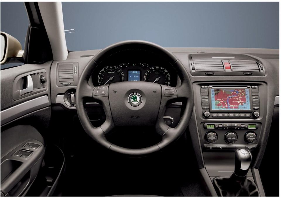
12 10 Cockpit Fig. 1 Certain items of equipment shown in the illustration are only fitted to particular model versions or are optional items of equipment.

13 Cockpit 11 Cockpit An overview This general view is designed to help you to quickly become familiar with the instruments, gauges and controls. A1 A2 A3 A4 A5 Electric power-operated window* Electric exterior mirror adjustment* Air outlet vents Lever for the multi-functional switch: Turn signal light, headlight and parking light, headlight flasher Speed regulating system* Steering wheel: with horn with driver airbag with pushbuttons for radio and mobile phone* A6 Instrument cluster: Instruments and indicator lights A7 Lever for the multi-functional switch: Multi-functional indicator* A8 A9 A10 A11 A12 A13 A14 Windshield wiper and wash system Control dial for heating on the driver's seat* Air outlet vents Switch for hazard warning lights Storage compartment on the dash panel Radio* Control dial for heating on the front passenger seat*..... Storage compartment on the front passenger side A15 Switch for the front passenger airbag* (in front passenger A16 A17 A18 A19 A20 A21 A22 A23 A24 stowage compartment) Front passenger airbag* Fuse carrier (on side of dash panel) Light switch Control dial for the instrument lighting and control dial for the headlight beam range regulation Bonnet release lever Storage compartment on the driver's side Lever for adjusting the steering wheel Ignition lock Depending on equipment fitted: Operating controls for the heating Operating controls for Climatic* , Operating controls for Climatronic* A25 Depending on equipment fitted: Switch for the ESP* Switch for TCS A26 A27 A28 A29 Front and rear parking aid* Depending on equipment fitted: Gearshift lever (manual gearbox) Selector lever (6-speed automatic gearbox)* Selector lever (automatic DSG)* Tyre inflation pressure-control system* Depending on equipment fitted: Rear ashtray - high centre console* Using the system Safety Driving Tips General Maintenance Breakdown assistance Technical Data

14 12 Cockpit A30 Storage compartment* Indicator light for a switched off front seat passenger airbag* Note Equipment which is marked * is only standard on certain vehicle model versions or only suppliable as optional equipment for certain models. Vehicles with factory-fitted radio, mobile phone, navigation system, CD player etc. are supplied with separate instructions for operating such equipment. The arrangement of the controls and switches and the location of some items on right-hand drive models may differ from that shown in page 10, fig. 1. The symbols on the controls and switches are the same as for left-hand drive models.

15 Instruments and Indicator/Warning Lights 13 Instruments and Indicator/Warning Lights General view of the instrument cluster Fig. 2 Instrument cluster A1 A2 A3 A4 A5 Engine revolutions counter page 14 Coolant temperature gauge page 14 Fuel gauge page 14 Speedometer Display: with counter for distance driven page 15 with Service Interval Display page 16 with digital clock page 17 with Multi-functional indicator* page 18 A6 with Information display* page 23 Clock-set button / reset button When the lights are switched on, the instrument cluster is illuminated. Using the system Safety Driving Tips General Maintenance Breakdown assistance Technical Data

16 14 Instruments and Indicator/Warning Lights Engine revolutions counter The start of the red zone in the revolutions counter A1 page 13, fig. 2 indicates the maximum permissible engine speed for all gears for an engine which has been run in and operating at a normal temperature. You should shift into the next higher gear before this red zone is reached, or move the selector lever into position D if your car is fitted with an automatic gearbox. One should shift to the next lower gear at the latest when the engine is no longer running smoothly. Avoid high engine speeds during the running-in period page 221. Caution The needle of the revolutions counter must on no account move into the red zone of the scale - risk of engine damage! For the sake of the environment Shifting up early helps you save fuel and reduce the operating noise of your vehicle. Coolant temperature gauge The coolant temperature gauge A2 page 13, fig. 2 operates only when the ignition is switched on. In order to avoid any damage to the engine, please pay attention to the following notes regarding the temperature ranges: Cold range If the pointer is still in the left-hand area of the scale it means that the engine has not yet reached its operating temperature. Avoid running at high engine speeds, at full throttle and at severe engine loads. The operating range The engine has reached its operating temperature as soon as the pointer moves into the mid-range of the scale. The pointer may also move further to the right at high engine loads and high outside temperatures. This is not critical provided the warning symbol in the instrument cluster does not flash. If the symbol in the instrument cluster flashes it means that either the coolant temperature is too high or the coolant level is too low. Please refer to the guidelines page 35, Coolant temperature/coolant level. Pay attention to the warning notes page 248, Working in the engine compartment before opening the bonnet and inspecting the coolant level. Caution Additional headlights and other attached components in front of the fresh air inlet impair the cooling efficiency of the coolant. There is then a risk of the engine overheating at high outside temperatures and high engine loads! Fuel gauge The fuel gauge A3 page 13, fig. 2 only operates when the ignition is switched on.

17 Instruments and Indicator/Warning Lights 15 The fuel tank has a capacity of about 55 litres (on vehicles with four-wheel drive approx. 60 litres). The warning symbol in the instrument cluster lights up when the pointer reaches the reserve marking. There are now about 8 litres of fuel remaining in the tank. This symbol is a reminder for you, that you must refuel. Counter for distance driven The following will be displayed in the information display*: Please refuel! (Please refuel!) A peep sounds as an additional warning signal. Caution Never run the fuel tank completely empty! An irregular fuel supply can result in poor ignition or misfiring. Unburnt fuel may get into the exhaust system and damage the catalytic converter. Fig. 3 Display: Trip counter for distance driven Speedometer Warning against excessive speeds* An acoustic warning signal will sound when the vehicle speed exceeds 120 kilometres per hour. The acoustic warning signal will switch off again when the vehicle speed goes below this speed limit. Note This function is only valid for some countries. The distance which you have driven with your vehicle is shown in kilometers (km). On certain model versions, the readout is shown in miles. The kilometer counter for distance driven is shown on the display when the ignition is switched off. The trip counter for distance driven is shown on the display after switching on the ignition. You can then switch over to the counter display with the reset button. Reset button By briefly pressing the reset button A6 page 13, fig. 2 you can switch over from the trip counter to the kilometer counter. In order to recognize which counter for the distance driven is shown on the display at that moment, trip fig. 3 appears after the trip counter. If you hold the reset button A6 pressed for about 1 second, the trip counter is set back to zero. If you hold the reset button A6 pressed for longer than 2 seconds when the ignition is switched on, a display regarding the kilometers still to be Using the system Safety Driving Tips General Maintenance Breakdown assistance Technical Data
 A peep sounds as an additional warning signal. Caution Never run the fuel tank completely empty! An irregular fuel supply can result in poor ignition or misfiring.")
18 16 Instruments and Indicator/Warning Lights driven and the days until the following service interval (for this the trip counter is not set back) appears page 16. Service Interval Display Counter for distance driven (trip) The counter for distance driven indicates the total distance in kilometers or miles which the vehicle has been driven. Trip counter for distance driven The trip counter indicates the distance which you have driven since this counter was last reset - in steps of 100 metres or 1/10 of a mile. Fault display def will appear as a constant text in the display if there is a fault in the instrument cluster. Have the fault rectified as soon as possible by a specialist workshop. Never seek to adjust the trip counter for distance driven while driving for safety reasons! Note On vehicles without multi-functional indicator or information display, both counts of the counters are shown simultaneously on the display. Fig. 4 Service Interval Display: Note Depending on the equipment installed in the vehicle, the text can differ slightly on the display. Service Interval Display A key symbol appears in the counter display for distance driven about 15 days before reaching the due date for the service fig. 4. The remaining distance to be driven will be indicated for 10 seconds next to the key symbol and then the remaining number of days to the due date for the service inspection. The following will be displayed in the information display*: Service in... km or... days The kilometre indicator or the days indicator reduces in steps of 100 km or days until the service due date is reached. The following text appears as a flashing key symbol as soon as the due date for the service is reached.

19 Instruments and Indicator/Warning Lights 17 The following will be displayed in the information display*: Service now! The display disappears within 20 seconds after switching on the ignition. The trip counter is also displayed after pressing the reset button for the trip counter (for more than 1 second). Display regarding the distance and days until the following service interval You can have the distance still to be driven and the days until the following service interval displayed at any time as follows: Switch on the ignition and press the reset button A6 page 13, fig. 2 for more than 2 seconds. A key symbol is displayed on the display of the counter for the distance driven. The remaining distance to be driven will be indicated for 10 seconds next to the key symbol and then the remaining number of days to the due date for the service inspection. Resetting Service Interval Display We recommend having this resetting performed by a specialist garage. Specialist garage: resets the memory of the display after the appropriate inspection makes an entry in the Service schedule affix the sticker with the entry of the following service interval to the side of the dash panel on the driver's side. The service interval displays can also be reset as follows by using the reset button A6 page 13, fig. 2 on the trip counter: Switch off the ignition, press the reset button of the trip counter for distance driven and hold it down. Switch the ignition on and release the reset button. Now turn the reset button to the right. The service interval displays are reset. Caution We recommend that you do not reset the Service Interval Display yourself otherwise this can result in the service interval display being incorrectly set, which may also result in problems with operation of your vehicle. Note Never reset the display between service intervals otherwise this may result in incorrect readouts. Information is retained in the Service Interval Display also after the battery of the vehicle is disconnected. It is necessary to re-code the Service Interval Display if a new instrument cluster is installed during repair work. This work is carried out by a specialist garage. The data displayed is the same after resetting the display with flexible service intervals (QG1) using the reset button as that for a vehicle with fixed service intervals (QG2). We therefore recommend having the Service Interval Display reset only by a Škoda dealer who is familiar with the procedure for resetting the display with a vehicle system tester. Please refer to the brochure Service schedule for extensive information about the service intervals. Digital clock A clock-set button A6 is installed on the bottom left beside the speedometer for adjusting the clock page 13, fig. 2. Set hours Turn the reset button to the left. Using the system Safety Driving Tips General Maintenance Breakdown assistance Technical Data

20 18 Instruments and Indicator/Warning Lights Setting minutes Turn the reset button to the right. The clock should not be adjusted while driving for safety reasons but only when the vehicle is stationary! Note In certain national versions the displays appear in the Imperial system of measures. Memory Multi-functional indicator (onboard computer)* Introduction The multi-functional indicator appears in the display fig. 5 or in the information display page 23, fig. 10 depending on the equipment fitted to your vehicle. The multi-functional indicator offers you a range of useful information. The outside temperature page 20 Current fuel consumption page 20 Average fuel consumption page 20 Range page 21 Distance driven page 21 Average speed page 21 Driving time page 21 Warning against excessive speeds* page 22 Fig. 5 Multi-functional indicator The multi-functional indicator is equipped with two automatic memories. The selected memory is displayed in the middle of the display field fig. 5. The data of the single-trip memory (memory 1) is shown if a 1 appears in the display. A 2 shown in the display means that data relates to the total distance memory (memory 2). Switching of the memory takes place with the button AB page 19, fig. 6. Single-trip memory (memory 1) The single-trip memory collates the driving information from the moment the ignition is switched on until it is switched off. New data will also flow

21 Instruments and Indicator/Warning Lights 19 into the calculation of the current driving information if the trip is continued within 2 hours after switching off the ignition. The memory will be automatically erased, on the other hand, if the trip is interrupted for more than 2 hours. Using the system Total-trip memory (memory 2) The total distance driven memory gathers data from any number of individual journeys up to a total of 99 hours and 59 minutes driving or kilometres driven. The memory is deleted when either of these limits is reached and the calculation starts from anew. The total-trip memory will not, contrary to the single-trip memory, be deleted after a period of interruption of driving of 2 hours. Note All information in the memory is erased if the battery of the vehicle is disconnected. Fig. 6 Multi-functional indicator: Controls The rocker switch A and the button AB are located in the grip of the window wiper lever fig. 6. Selecting the memory Repeated short-term pressing of the button AB allows one to select the individual memories. Selecting the functions Press the rocker switch A up or down. This will cause the individual functions of the multi-functional indicator to appear in the display one after the other. Setting function to zero Select the memory you want. Press button AB for more than 1 second. Using the system Safety Driving Tips General Maintenance Breakdown assistance Technical Data
22 20 Instruments and Indicator/Warning Lights The following readouts of the selected memory will be set to zero by button AB : average fuel consumption, distance driven, average speed, Driving time. You can only operate the multi-functional indicator when the ignition is switched on. After the ignition is switched on, the function displayed is the one which you last selected before switching off the ignition. If the outside temperature drops below +4 C, the outside temperature indicator with a snow flake symbol appears. The symbol warns the driver of the possible danger of ice on the road. After the rocker switch A is pressed, the function displays the one which you last selected before switching off the ignition. The outside temperature appears in the display when the ignition is switched on. The correct outside temperature will be indicated with a delay of 5 minutes. If the vehicle is stationary (or driven at a very low speed) the temperature indicated may be slightly higher than the actual outside temperature because of heat radiated by the engine. If the outside temperature drops below +4 C, a snow flake symbol (warning signal for ice on the road) appears before the temperature indicator fig. 7 and a warning signal sounds. Do not only rely upon the information given on the outside temperature display that there is no ice on the road. Please note that black ice may also be present on the road surface even at temperatures around +4 C - warning, drive with care! The outside temperature Current consumption The current fuel consumption level is shown in the display in litres/100 km. This information can help you to adapt your style of driving to the fuel consumption you wish to achieve. The display appears in litres/hour if the vehicle is stationary or driving at a low speed. Average fuel consumption Fig. 7 Multi-functional indicator: the outside temperature The average fuel consumption since the memory was last erased is shown in the display in litres/100 km page 18. This information can help
23 Instruments and Indicator/Warning Lights 21 you to adapt your style of driving to the fuel consumption you wish to achieve. If you wish to determine the average fuel consumption over a certain period of time you must first erase the memory at the start of the new measurement using the button AB page 19, fig. 6. A zero appears in the display for the first 100 m you drive after erasing the memory. The indicated value will be updated every 5 seconds while you are driving. Note The amount of fuel consumed will not be indicated. Range The estimated range in kilometres is shown on the display. It indicates the distance you can still drive with your vehicle based on the present level of fuel in the tank for the same style of driving. The readout is shown in steps of 10 km. The fuel consumption for the last 50 km is taken as a basis for calculating the range. If you drive in a more economical manner from this moment on, the range will be increased accordingly. You first drive 50 km if the readout is reset (after disconnecting the battery) before a new readout for the range is displayed. Distance driven particular time of day you must first erase the memory at this moment in time by pressing the button AB page 19, fig. 6. The maximum distance indicated in both switch positions is 9999 km. The indicator is set back to null if this period is exceeded. Average speed The average speed since the memory was last erased is shown in the display in km/hour page 18. If you wish to determine the average speed over a certain period of time you must first erase the memory at the start of the new measurement using the button AB page 19, fig. 6. A zero appears in the display for the first 100 m you drive after erasing the memory. The indicated value will be updated every 5 seconds while you are driving. Driving time The driving time which has elapsed since the memory was last erased, appears in the display page 18. If you wish to calculate the driving time from a particular time of day you must first erase the memory at this moment in time by pressing the button AB page 19, fig. 6. The maximum distance indicated in both memories is 99 hours and 59 minutes. The indicator is set back to null if this period is exceeded. The distance driven since the memory was last erased appears in the display page 18. If you wish to calculate the distance driven from a Using the system Safety Driving Tips General Maintenance Breakdown assistance Technical Data
24 22 Instruments and Indicator/Warning Lights Warning against excessive speeds* Warning against excessive speeds 1) Fig. 8 Speed setting This function enables you to set a speed limit, e.g. if you drive in town. A text in the display is intended to draw your attention to the fact that you have exceeded the set speed limit. You can set the desired speed limit as follows: Select the menu Speed warning --- km/h (warning at --- km/h). You can drive at the desired speed, e.g. 50 km/h Press the button AB fig. 9 - Speed warning 50 km/h (warning at 50 km/h) is shown on the display. If you now exceed the set speed limit, Speed 50 km/h exceeded (speed 50 km/h exceeded) will be shown on the display. This display will be shown until you have reduced the speed to the set speed limit. A peep sounds as an additional warning signal. The set speed limit remains stored in the memory, also when the ignition is switched off and on; it can only be erased by pressing the button AB for more than 1 second. Fig. 9 Multi-functional indicator: Controls 1) Valid for vehicles with information display.
25 Instruments and Indicator/Warning Lights 23 Information display* Introduction The display of text is possible in the following languages: Czech, English, German, French, Italian, Spanish, Portuguese. You can select the desired language in the setting menu page 28. The following information can be shown in the display (depending on the equipment installed on the vehicle): Fig. 10 Instrument cluster: Information display Main menu page 24 Door, luggage compartment door and bonnet ajar page 25 warning Service Interval Display page 16 Selector lever positions of the 6-speed automatic page 150 gearbox Selector lever positions of the automatic DSG page 157 The information display provides you with information in a convenient way concerning the current operating state of your vehicle. The information system also provides you with data (depending on the equipment installed in the vehicle) relating to the radio, mobile phone, multi-functional indicator, navigation system and automatic gearbox. Certain functions and operating conditions are always being checked on the vehicle when the ignition is switched on and also while driving. Functional faults, if required repair work and other information are indicated by red symbols page 27 and yellow symbols page 28. Lighting up of these symbols is combined with an acoustic warning signal. Information and texts giving warnings are also shown in the display page 30. Using the system Safety Driving Tips General Maintenance Breakdown assistance Technical Data
26 24 Instruments and Indicator/Warning Lights Main menu You can select the menu through the rocker switch A. When the pushbutton AB is briefly pressed, the information you have selected is displayed. You can select the following information (depending on the equipment installed on the vehicle): Fig. 11 Information display: Menu MF Display page 18 The outside temperature Current consumption Average fuel consumption Range Distance driven Average speed Driving time Warning against excessive speeds Audio page 25 Navigation page 26 Telephone page 167 Vehicle status page 26 Fig. 12 Information display: Controls You can activate the MAIN MENU by pressing the rocker switch A fig. 12 for more than 1 second. Setup page 28 Time Winter tyres Language Units Lights & Vision Aux. Heating (auxiliary heating) Back
27 Instruments and Indicator/Warning Lights 25 Display off After selecting the menu Display off the display is switched off. Press rocker switch A for at least 1 second to switch the display on again. The menu Audio is only displayed when the Radio* is switched on. The menu Navigation is only displayed when the Navigation* is switched on. Aux. Heating (auxiliary heating) is only then displayed, if the vehicle is fitted with auxiliary heating*. Note If you do not activate the information display at that moment, the menu shifts to one level higher every 10 seconds. The door, luggage compartment door and bonnet ajar warning lights up when at least one of the three items door, luggage compartment or bonnet are not closed when the ignition is turned on. The symbol indicates which door is still open or whether the luggage compartment door or bonnet is not closed fig. 13. The symbol goes out as soon as the doors, luggage compartment door and bonnet are completely closed. As an additional warning signal, a 3 time peep sounds if the car is driven at a speed of more than 6km/hour and if the door, engine or luggage compartment door is open. Audio Door, luggage compartment door and bonnet ajar warning Fig. 14 Information display: Radio display Fig. 13 Information display: Door warning These displays appear in addition to the normal information in the radio display. Using the system Safety Driving Tips General Maintenance Breakdown assistance Technical Data
28 26 Instruments and Indicator/Warning Lights Operation of the radio system is described in separate operating instructions to be found in the on-board literature. Navigation system* Auto Check Control Vehicle condition The controls for the navigation system, radio, CD player are located in the centre console on both sides of the monitor screen. Navigation data is also shown in the information display of the instrument cluster. Information and warning texts are displayed preferentially when the navigation system is switched on. Operation of the navigation system is described in separate operating instructions to be found in the on-board literature. Fig. 15 Information display: Display of operational fault The Auto Check Control carries out a check of certain functions and vehicle components. The check is performed constantly when the ignition is switched on, both when the vehicle is stationary, as well as when driving. Operational faults, urgent repairs, service work or other information appear in the display of the instrument cluster. The displays are shown with a red or yellow light symbol depending on the priority of the message. The red symbols indicate danger (priority 1) while the yellow symbols indicate a warning (priortity 2). Information for the driver may also appear in addition to the symbols page 30. There is at least one error message to be read when the term Vehicle status is flashing in the main menu. After selecting this menu the first of the error messages is displayed. If there are several error messages, they
29 Instruments and Indicator/Warning Lights 27 are shown on the display under the message e.g. 01/03 fig. 15. This display indicates that the first of a total of three error messages should be displayed. The respective symbols light up one after the other in an interval of 5 seconds. Investigate the displayed faults as soon as possible. Red symbols A red symbol signals danger. As long as the operational faults are not rectified, the symbols are always indicated again. After the first display, the symbols are indicated without information for the driver. If there is no error message, after selecting the menu Vehicle status the message Status OK is shown on the display. If a fault occurs, a warning signal will also sound in addition to the symbol and text in the display: Priority 1 - three warning signals Priority 2 - one warning signal Fig. 16 Information display: Oil pressure is low Proceed as follows if a red symbol is displayed: Stop the vehicle. Switch the engine off. Investigate the function indicated. Obtain professional assistance. Meaning of the red symbols: Coolant level too low/coolant temperature too high page 35 Engine oil pressure too low page 37 Using the system Safety Driving Tips General Maintenance Breakdown assistance Technical Data
30 28 Instruments and Indicator/Warning Lights Three successive warning signals will sound if a red symbol appears. If several operational faults of priority 1 exist, the symbols appear one after the other and are each illiminated for about 5 seconds. Yellow symbols A yellow symbol signals a warning. Fuel level low page 36 Check engine oil level, page 38 engine oil sensor faulty Brake pad worn page 36 Washer fluid level low page 36 One warning signal will sound if a yellow symbol appears. If several operational faults of priority 2 exist, the symbols appear one after the other and are each illiminated for about 5 seconds. Settings Fig. 17 Information display: Fuel level low Check the relevant function as soon as possible. The meaning of the yellow symbols: Fig. 18 Setting the clock
31 Instruments and Indicator/Warning Lights 29 You can change certain settings by means of the information display. The current setting is shown on the information display in the respective menu at the top below the line page 28, fig. 18. You can select the following information (depending on the equipment installed on the vehicle): Time Winter tyres Language Units Lights & Vision Aux. Heating (auxiliary heating) Back After selecting the menu Back you will reach one level higher in the menu. Setting units Here you can set the units for temperature, consumption and distance driven. Setting lights Here you can switch on or off the function convenience turn signal page 68. Furthermore you can set how long the light should stay on for the function Coming/Leaving Home page 66. After selecting the menu Factory setting the factory setting is established again. Setting clock Here you can set the time, the time format (12 or 24 hour indicator) and the time change summer/winter time. Setting for winter tyre speed Here you can set at which speed a warning signal should sound. These functions are used for e.g on winter tyres with the permissible maximum speed less than the maximum speed of the vehicle page 266. When exceeding the speed, the following is displayed on the information display*: Speed warning Language setting Here you can set in which language the warning and information texts should be displayed. After selecting the language, e.g. English, the following is displayed on the information display: Language: english set Using the system Safety Driving Tips General Maintenance Breakdown assistance Technical Data
32 30 Instruments and Indicator/Warning Lights Warning lights An overview The warning lights indicate certain functions or faults. Fig. 19 Instrument cluster with warning lights Turn signal lights (to the left) page 32 Turn signal lights (to the right) page 32 Main beam page 32 Low beam page 32 Rear fog light page 32 Electronic immobiliser page 32 Diesel particle filter (diesel engine) page 33 Bulbs page 33
33 Instruments and Indicator/Warning Lights 31 Electromechanical power steering page 33 Control system for exhaust page 34 EPC fault light (petrol engine) page 34 Glow plug system (diesel engine) page 34 Airbag system page 35 Coolant temperature/coolant level page 35 Brake pad wear* page 36 Fluid level in windshield washer system* page 36 Fuel reserve page 36 Engine oil pressure page 37 Bonnet page 37 Open door* page 37 Engine oil level* page 38 Tyre pressure* page 38 Selector lever lock* page 38 Antilock brake system (ABS) page 38 Traction control system (TCS) page 39 Electronic stability programme (ESP)* page 40 Dynamo page 40 Brake system page 40 Seat belt warning light* page 41 If you do not pay attention to the warning lights coming on and the corresponding descriptions and warning notes, this may result in severe body injuries or major vehicle damage. The engine compartment of your car is a hazardous area. There is a risk of injuries, scalding, accidents and fire when working in the engine compartment, e.g. inspecting and replenishing oil and other fluids. It is also essential to observe all warnings page 248. Note Arrangement of the indicator lights depends on the model and model version. The symbols shown in the following functional description are to be found as indicator lights in the instrument cluster. Operational faults are shown in the instrument cluster as red symbols (priority 1 - danger) or yellow symbols (priority 2 - warning). Using the system Safety Driving Tips General Maintenance Breakdown assistance Technical Data
34 32 Instruments and Indicator/Warning Lights Turn signal system Either the left or right indicator light flashes depending on the position of the turn signal lever. The indicator light flashes at twice its normal rate if a turn signal light fails. This does not apply when towing a trailer. Switching on the hazard warning light system is switched on will cause all of the turn signal lights as well as both indicator lights to flash. Further information about the turn signal system page 68. Main beam Electronic immobiliser Data is compared between the ignition key and the control unit when switching on the ignition. The indicator light will light up for a few seconds when ignition key authorisation is confirmed. The warning light will start flashing continuously if a non-authorised ignition key (for example the wrong ignition key) has been used. The engine cannot be started page 45. It is only possible to start the engine of the vehicle with a Genuine Škoda key with the matching code. The following text will be displayed in the information display*: Immobilizer active The indicator light comes on when the main beam is selected or also when the headlight flasher is operated. Further information about the main beam page 68. Low beam The indicator light comes on when low beam is selected page 63. The rear fog light The warning light comes on when the rear fog lights are operating page 65.
35 Instruments and Indicator/Warning Lights 33 Diesel particle filter (diesel engine) In the diesel particle filter the resulting soot particles are collected and burnt during the combustion of diesel fuel. If the warning light remains on despite this measure, the following text appears in the display of the instrument cluster: Engine fault Workshop!. In this case contact a specialist garage to obtain assistance. Please pay attention to the traffic regulations and speed limits. Note It is prohibited to use biofuel and diesel fuel mixture (RME) for vehicles with diesel engines which are fitted with diesel particle filter. Bulbs Fig. 20 Vehicle data sticker Code 7GG on the vehicle data sticker fig. 20 indicates that your vehicle is equipped with a diesel particle filter. The vehicle data sticker page 303, fig. 234 is located on the floor of the luggage compartment and is also stated in the Service schedule. The soot particles, which result from the combustion of diesel fuel, are collected in the diesel particle filter. If the filter is full, the warning light lights up in the instrument cluster. The soot particles must be burned in the filter. The combustion is performed when you are driving at least 60 km/h for 5 to 10 minutes. The warning light goes out. The warning light comes on for a few seconds after ignition is switched on and goes out after several seconds. If the warning light does not go out or comes on when driving, a bulb in the headlights of the rear parking light or in the brake lights is defective. The following text e.g will be displayed in the information display*: Dipped beam front left defective! A peep sounds as an additional warning signal. Electromechanical power steering The warning light comes on for a few seconds when the ignition is switched on. Using the system Safety Driving Tips General Maintenance Breakdown assistance Technical Data
36 34 Instruments and Indicator/Warning Lights If the warning light after switching on the ignition or when driving lights up continuously, a fault exists in the electromechanical power steering. If the yellow warning light lights up, this indicates a partial failure of the power steering and the steering forces can be greater. If the red warning light lights up, this indicates a complete failure of the power steering and the steering assist has failed (significantly higher steering forces). If the red warning light lights up, three peeps sound as an additional warning signal. Further information page 219, Electromechanical power steering. Contact your specialist garage if the power steering is defective. Note If the yellow warning light goes out after starting the engine again and a short drive, it is not necessary to visit a specialist garage. If the battery has been disconnected and reconnected, the yellow warning light comes on after switching on the ignition. The warning light must go out after driving a short distance. Control system for exhaust gases The warning light comes on after the ignition has been switched on. If the warning light does not go out after starting the engine or it lights up or flashes when driving, a fault exists in an exhaust relevant component. The engine management system selects an emergency programme which enables you to drive to the nearest specialist garage by adopting a gentle style of driving. The following text will be displayed in the information display*: Emissions workshop! EPC fault light (petrol engine) The (Electronic Power Control) warning light comes on for a few seconds when the ignition is switched on. If the warning light does not go out or lights up after starting the engine, a fault exists in the engine control. The engine management system selects an emergency programme which enables you to drive to the nearest specialist garage by adopting a gentle style of driving. The following text will be displayed in the information display*: Engine fault Workshop! (Engine fault workshop!) Glow plug system (diesel engine) The indicator light lights up for a cold engine when switching on the igntion (pre-heat position) 2 page 139. Start the engine just as soon as the indicator light goes out. The glow plug indicator light will come on for about 1 second if the engine is at a normal operating temperature or if the outside temperature is above +5 C. This means that you can start the engine right away. There is a fault in the glow plug system if the indicator light does not come on at all or lights up continuously. Contact a specialist garage as soon as possible to obtain assistance.
SIMPLY CLEVER. ŠKODA Fabia OWNER'S MANUAL
 SIMPLY CLEVER ŠKODA Fabia OWNER'S MANUAL Introduction You have opted for a ŠKODA our sincere thanks for your confidence in us. Your new ŠKODA offers you a vehicle featuring the most modern engineering
ŠkodaOctavia Tour OWNER S MANUAL SIMPLY CLEVER
 ŠkodaOctavia Tour OWNER S MANUAL SIMPLY CLEVER Introduction You have opted for a Škoda - our sincere thanks for your confidence in us. Your new Škoda offers you a vehicle featuring the most modern engineering
SIMPLY CLEVER. ŠKODA Citigo OWNER'S MANUAL
 SIMPLY CLEVER ŠKODA Citigo OWNER'S MANUAL Preface You have opted for a ŠKODA our sincere thanks for your confidence in us. Your new ŠKODA offers you a vehicle featuring the most modern engineering and
SIMPLY CLEVER. ŠKODA Yeti OWNER'S MANUAL
 SIMPLY CLEVER ŠKODA Yeti OWNER'S MANUAL Introduction You have opted for a ŠKODA our sincere thanks for your confidence in us. Your new ŠKODA offers you a vehicle featuring the most modern engineering
SIMPLY CLEVER. ŠKODA Octavia OWNER'S MANUAL
 SIMPLY CLEVER ŠKODA Octavia OWNER'S MANUAL Introduction You have opted for a ŠKODA our sincere thanks for your confidence in us. Your new ŠKODA offers you a vehicle featuring the most modern engineering
ŠKODA Fabia OWNER'S MANUAL
 ŠKODA Fabia OWNER'S MANUAL Introduction You have opted for a Škoda - our sincere thanks for your confidence in us. Your new Škoda offers you a vehicle featuring the most modern engineering and a wide range
SIMPLY CLEVER. ŠKODA Octavia Owner's Manual
 SIMPLY CLEVER ŠKODA Octavia Owner's Manual Preface You have opted for a ŠKODA our sincere thanks for your confidence in us. Your new ŠKODA offers you a vehicle featuring the most modern engineering and
Audi A3 Audi A3 Sportback Quick reference guide
 Audi A Audi A Sportback Quick reference guide Dear Audi Driver, This quick reference guide gives you a brief introduction to the main features and controls of your vehicle. However, it cannot replace the
Table of Contents. Introducing AYGO. Accessing your vehicle 2 3. Lights 9. Wipers 10. Electric windows 4. Gear change 11
 AYGO Brief Guide Table of Contents Accessing your vehicle 2 3 Electric windows 4 Steering wheel (Vehicles with an adjustable type) 4 Seat and seat belt adjustment 5 Instrument Panel overview 6 Instrument
SIMPLY CLEVER. ŠKODA Fabia Owner's Manual
 SIMPLY CLEVER ŠKODA Fabia Owner's Manual Preface You have opted for a ŠKODA our sincere thanks for your confidence in us. Your new ŠKODA offers you a vehicle featuring the most modern engineering and a
2009 QUICK REFERENCE GUIDE GET INFORMED. ROLL.
 xb 2009 QUICK REFERENCE GUIDE GET INFORMED. ROLL. 2009 Scion xb This Quick Reference Guide is a summary of basic vehicle operations. It contains brief descriptions of fundamental operations so you can
SIMPLY CLEVER. ŠKODA Citigo Owner's Manual
 SIMPLY CLEVER ŠKODA Citigo Owner's Manual Layout of this Owner's Manual (explanations) This Owner's Manual has been systematically designed to make it easy for you to search for and obtain the information
Multi-information Display (see MID )
") Driving Position Memory (see Seats ) Power Mirrors (see Mirrors ) Indicators/Gauges (see Instrument Panel ) Multi-information Display (see MID ) HomeLink (see HomeLink ) Navigation System (see Navigation
Driving Position Memory (see Seats ) Power Mirrors (see Mirrors ) Indicators/Gauges (see Instrument Panel ) Multi-information Display (see MID ) HomeLink (see HomeLink ) Navigation System (see Navigation
Scion xb. Pocket Reference Guide. <http://www.scion.com/>, Contact
 EMAIL US , Contact 2006 CHAT On weekdays you can chat with a Scion Customer Advocate. , Have a Question? or Contact CALL US For the Scion Customer Experience
xd 2010 QUICK REFERENCE GUIDE GET INFORMED. ROLL.
 xd 2010 QUICK REFERENCE GUIDE GET INFORMED. ROLL. 2010 Scion xd This Quick Reference Guide is a summary of basic vehicle operations. It contains brief descriptions of fundamental operations so you can
ŠkodaOctavia SUPPLEMENT TO THE OWNER'S MANUAL
 SIMPLY CLEVER ŠkodaOctavia SUPPLEMENT TO THE OWNER'S MANUAL Technical Changes 11/2010 Introduction 1 Introduction Seat heaters* This supplement replaces the Owner's manual OCTAVIA Edition 05.10 referred
ŠkodaOctavia SUPPLEMENT TO THE OWNER'S MANUAL
 SIMPLY CLEVER ŠkodaOctavia SUPPLEMENT TO THE OWNER'S MANUAL Technical Changes 11/2009 Introduction 1 Introduction Electronic stability programme (ESP)* This supplement replaces the Owner's manual Edition
ŠkodaOctavia Supplement - for vehicles with LPG drive
 SIMPLY CLEVER ŠkodaOctavia Supplement - for vehicles with LPG drive 01/2011 Supplement - for vehicles with LPG drive (natural gas) 1 Supplement - for vehicles with LPG drive (natural gas) This supplement
QUICK GUIDE WEB EDITION WELCOME TO YOUR NEW VOLVO! VOLVO C30
 VOLVO C30 QUICK GUIDE WEB EDITION WELCOME TO YOUR NEW VOLVO! Getting to know your new car is an exciting experience. Look through this Quick Guide in order to quickly and easily learn some of the most
How you can contribute to a cleaner environment
 How you can contribute to a cleaner environment The fuel consumption of your Škoda - and thus the level of pollutants contained in the exhaust - is also determined by how you drive. The noise level and
4008 FEATURES AND SPECIFICATIONS
 ACTIVE BODYSTYLE 5 door compact SUV SAFETY Driver and front passenger airbags Front side airbags Full length curtain airbags Driver knee airbag ABS with Electronic Brake Force Distribution (EBFD) Emergency
INSTRUMENT PANEL. 1995 Volvo 850 DESCRIPTION & OPERATION. 1995-96 ACCESSORIES & EQUIPMENT Volvo Instrument Panels
 INSTRUMENT PANEL 1995 Volvo 850 1995-96 ACCESSORIES & EQUIPMENT Volvo Instrument Panels 850 WARNING: When working around steering column and before performing repairs, disconnect and shield battery ground
Operating Instructions Display, graphic. Numeric language
 Operating Instructions Display, graphic Numeric language Contents Numeric language, general... 1 Numeric language, general... 1 Display control stalk... 1 Text strings... 1 Stop message... 2 Change language...
Owner s Manual. Operation, Safety and Maintenance TS 1515-A-08 MOVANO. Copyright by Vauxhall Motors Ltd., England.
 Owner s Manual MOVANO Operation, Safety and Maintenance Reproduction or translation, in whole or in par ts, is not permitted without prior written consent from Vauxhall Motors Ltd. All rights as understood
Workshop Repair Manual
 Workshop Repair Manual N.T. 2863A All types Basic manual: M.R. 302 - M.R. 307 - M.R. 311 - M.R. 312 M.R. 291 - M.R. 293 77 11 196 407 OCTOBER 1997 Edition Anglaise "The repair methods given by the manufacturer
ŠkodaFabia ŠkodaRoomster SUPPLEMENT TO THE OWNER'S MANUAL
 ŠkodaFabia ŠkodaRoomster SUPPLEMENT TO THE OWNER'S MANUAL Technical Changes 11/2010 SIMPLY CLEVER Introduction 1 Introduction This supplement to the FABIA Owner's manual Edition 05.10 and the ROOMSTER
Practical accident assistance
 Practical accident assistance A guideline for Mercedes-Benz customers Please note: Changes may have been made to the products since this brochure went to press (12/2009). This brochure has been compiled
XC60. Quick GUIDE Web Edition
 XC60 Quick GUIDE Web Edition WELCOME TO THE GLOBAL FAMILY OF VOLVO OWNERS! This Quick Guide provides a brief overview of the most common features and functions in your Volvo. The Owner s Manual and the
Transporter Fitting Locations No. 804 / 1
 Page 1 of 10 Transporter Fitting Locations No. 804 / 1 Pin connector assigment of selected connections Overview: 1 - Ignition/starter switch -D- On steering column Connector assigment chapter 2 - Onboard
2015 Scion tc Quick Reference Guide
 2015 Scion tc Quick Reference Guide 2015 Scion tc This Quick Reference Guide is a summary of basic vehicle operations. It contains brief descriptions of fundamental operations so you can locate and use
Wiring diagrams 14 1. Component key for wiring diagrams 1 to 29 Note: Not all the items listed will be fitted to all models
 Wiring diagrams 14 1 Component key for wiring diagrams 1 to 29 Note: Not all the items listed will be fitted to all models No Description 00200 Alternator with built-in regulator 00500 Battery 01001 Starter
Vehicle electrics in Polo Model Year 2002
 Service. Self-Study Programme 265 Vehicle electrics in Polo Model Year 2002 265_061 The range of electrical systems in new vehicles is expanding increasingly as a result of the ever more effective safety
2015 Scion xb Quick Reference Guide
 2015 Scion xb Quick Reference Guide 2015 Scion xb This Quick Reference Guide is a summary of basic vehicle operations. It contains brief descriptions of fundamental operations so you can locate and use
Mercedes-Benz Vito. Specifications
 Mercedes-Benz Vito Specifications Mercedes-Benz Technical Data Panel Van Specification Body Style Rated output (kw @ rpm) Max torque (Nm @ rpm) Injection Fuel consumption 1 (litres/100km) Front axle load
How To Use A 2010 Element
 Element 2 0 1 0 Technology Reference Guide Indicators/Info Display/TPMS Instrument Panel Indicators Indicators briefly appear with each engine start. Red and amber indicators are most critical. Blue and
The Crafter Electrical system
 Service Training Self-study Programme 370 Commercial Vehicles The Crafter Electrical system Design and function Innovations in automotive engineering are also taking place in the commercial vehicle segment.
The Touran Electrical system
 Service. Self-study programme 307 The Touran Electrical system Design and function The networking technology, used until now only in luxury class vehicles, will be a feature in compact vans, such as the
A name a commitment! These are the criteria which have characterized the development of dependable everyday cars up to the present time.
 A name a commitment! Automobile development has been a ŠKODA commitment since 1905. Even in those days, the trade press wrote enthusiastically above the Laurin & Klement Model A: Solidly built, dependable
University of Leicester. Vehicle Fleet Management Procedures
 University of Leicester Vehicle Fleet Management Procedures Estates & Facilities Management Division September 2011 1 Introduction The University fleet of vehicles includes all vehicles owned by the University
The Touareg Electrical System
 Service. Self-Study Programme 298 The Touareg Electrical System Design and Function Vehicles with off-road capability are no longer just utility vehicles for a limited group of people. At all levels in
ARTICLE BEGINNING * PLEASE READ THIS FIRST * MODEL IDENTIFICATION VIN LOCATION VIN CODE ID EXPLANATION
 Article Text ARTICLE BEGINNING 1993-96 MAINTENANCE Volkswagen Maintenance Information Golf III, GTI (1995-96), Jetta III Cabrio (1995-96) * PLEASE READ THIS FIRST * NOTE: For scheduled maintenance intervals
Exterior features. Rear parking sensors. Personalisation kits. puncture repair kit. Guide-me-home lighting
 Exterior features Personalisation kits These self-adhesive decals form part of a range of kits, very different one from another, which allow you to create a unique and attractive exterior for your vehicle.
Porsche Service. Cayenne (from MY 2008 for the following countries:
 Porsche Service Cayenne (from MY 2008 for the following countries: Abu Dhabi, Bahrain, Dubai, Jordan, Qatar, Kuwait, Lebanon, Oman, Saudi Arabia, Syria) Porsche Cayenne Maintaining driving pleasure No
CAR DAILY VEHICLE PRE CHECKS INFORMATION. Page 1 of 6
 Page 1 of 6 CAR DAILY VEHICLE PRE CHECKS INFORMATION There are approximately 2.5 million vehicles in national fleet in Ireland. As vehicles age they are subject to wear and tear and unless attended to
STEERING COLUMN CONTROLS
 STEERING COLUMN CONTROLS Ignition Switch... 2-1 Lighting/Turn Signal Control Lever... 2-5 Windshield Wiper and Washer Lever... 2-6 Rear Window WiperlWasher Switch (if equipped)... 2-8 Tilt Steering Lock
the alarm B If the vehicle is out of range when the button is pressed, the most recently stored status information will be shown.
 REMOTE KEY WITH PCC* personal car communicator Locks the doors and trunk and arms the alarm A. PCC* 1 Green light: vehicle is locked. 2 Yellow light: vehicle is unlocked. 3 Red light: alarm has been triggered.
Minibus Driving - Code of Practice
 Minibus Driving - Code of Practice RESPONSIBILITY The Minibus It is the responsibility of Campus Service Supervisor/Fleet Manager to ensure that all minibuses used by the University are in a roadworthy
Quick GUIDE Web Edition
 S60 Quick GUIDE Web Edition WELCOME TO THE GLOBAL FAMILY OF VOLVO OWNERS! Getting to know your new vehicle is an exciting experience. This Quick Guide provides a brief overview of the most common features
Octavia (1U) 17-Dashboard up to 00 identification Octavia (1U) 17-Dashboard up to 00 07 - Coding Octavia (1U) 17-Dashboard up to 00 10 - Adaptation
 17-Dashboard up to 00 identification Octavia (1U) 17-Dashboard up to 00 07 - Coding Octavia (1U) 17-Dashboard up to 00 10 - Adaptation") Octavia (1U) 17-Dashboard up to 00 identification Octavia (1U) 17-Dashboard up to 00 07 - Coding Octavia (1U) 17-Dashboard up to 00 10 - Adaptation Octavia (1U) 17-Dashboard from 01 identification Octavia
Octavia (1U) 17-Dashboard up to 00 identification Octavia (1U) 17-Dashboard up to 00 07 - Coding Octavia (1U) 17-Dashboard up to 00 10 - Adaptation Octavia (1U) 17-Dashboard from 01 identification Octavia
G-100/200 Operation & Installation
 G-100/200 Operation & Installation 2 Contents 7 Installation 15 Getting Started 16 GPS Mode Setup 18 Wheel Sensor Mode Setup 20 Fuel Calibration 23 Basic Operation 24 Telemetery Screen 27 Entering a Distance
Reference Guide and Step-by-Step Installation Manual. Table of Contents
 Part #674 Revision Date: 6.7.07 Reference Guide and Step-by-Step Installation Manual Some adjustable features listed on the following pages are NOT applicable for all applications. The year, make, and
New Caddy Panel Van. Commercial Vehicles
 New Commercial Vehicles Specifications Engine Cylinders 4 4 4 4 4 Capacity (cm 3 ) 1598 1968 1968 1968 1968 utput (kw @ r/min) 81 @ 5800 81 @ 4200 81 @ 4200 81 @ 4200 103 @ 4200 Torque (Nm @ r/min) 155
2006 Volkswagen Maintenance Schedule by Miles/Kilometers
 2.0 Liter Engine: Engine: Change engine oil and oil filter Engine: Check for leaks Service interval display: Reset (Where applicable) Exhaust system: Check for damage & leaks Battery: Check Door check
ENGLISH OWNER HANDBOOK. Alfa Services
 Cop Alfa Giulietta GB:Alfa 159 cop. LUM GB 15-09-2011 15:08 Pagina 1 ENGLISH OWNER HANDBOOK Alfa Services WHY CHOOSING GENUINE PARTS We really know your car because we invented, designed and built it:
Ex-Demonstrator 2016 Mitsubishi Triton MQ GLS Utility Double Cab 4dr Spts Auto 5sp 4x4 2.4DT [MY16]
![Ex-Demonstrator 2016 Mitsubishi Triton MQ GLS Utility Double Cab 4dr Spts Auto 5sp 4x4 2.4DT [MY16]](/thumbs/40/21188139.jpg "Ex-Demonstrator 2016 Mitsubishi Triton MQ GLS Utility Double Cab 4dr Spts Auto 5sp 4x4 2.4DT [MY16]") Contact: Blake Campaniello - E: bcampaniello@portsidemitsubishi.com.au T: 08 8345 7400 F: 08 8445 7112 1032 Port Road, Albert Park, South Australia 5014 61338 Ex-Demonstrator 2016 Mitsubishi Triton MQ
Contact: Blake Campaniello - E: bcampaniello@portsidemitsubishi.com.au T: 08 8345 7400 F: 08 8445 7112 1032 Port Road, Albert Park, South Australia 5014 61338 Ex-Demonstrator 2016 Mitsubishi Triton MQ
Ell STEERING COLUMN CONTROLS STEERING COLUMN CONTROLS
 STEERING COLUMN CONTROLS Ignition Switch........ 2-1 LightinglTurn Signal Control Lever... 2-5 Windshield Wiper and Washer Lever... 2-6 Rear Window Wiper/Washer Switch (if equipped)... 2-8 Tilt Steering
ŠkodaAuto CAR RADIO BEAT SIMPLY CLEVER
 ŠkodaAuto CAR RADIO BEAT SIMPLY CLEVER Contents 1 Contents Radio....................................... Radio - Overview............................. Important information........................ Anti-theft
Electronically Controlled Air Suspension (ECAS) for Trucks
 for Trucks") $2.50 Electronically Controlled Air Suspension (ECAS) for Trucks Maintenance Manual No. 36 Issued 7-99 ECAS System for 6 x 2 and 6 x 4 Vehicles with Rear Air Suspensions Service Notes Service Notes This
$2.50 Electronically Controlled Air Suspension (ECAS) for Trucks Maintenance Manual No. 36 Issued 7-99 ECAS System for 6 x 2 and 6 x 4 Vehicles with Rear Air Suspensions Service Notes Service Notes This
2014 Scion xd Quick Reference Guide
 2014 Scion xd Quick Reference Guide 2014 INDEX Scion xd OVERVIEW Engine maintenance 7 This Quick Reference Guide is a summary of basic vehicle operations. It contains brief descriptions of fundamental
Installing RNS-E SAT NAV for Audi A4
 As one of the major options on the A4 you can get a DVD Satellite Navigation System call the RNS-E. With the help of ebay these sat nav systems are now available to by at a rough cost of 650 plus the cost
Introduction. In this Self-study Programme we will explain to you the design and function of the CAN data bus. SSP 186/01
 Introduction The requirements relating to driving safety, driving comfort, exhaust emissions and fuel economy are are becoming ever more stringent. This entails more intensive information exchange between
OWNER S MANUAL RAM TRUCK DIESEL SUPPLEMENT
 2015 OWNER S MANUAL RAM TRUCK DIESEL SUPPLEMENT VEHICLES SOLD IN CANADA With respect to any Vehicles Sold in Canada, the name Chrysler Group LLC shall be deemed to be deleted and the name Chrysler Canada
2. READY TO SET OFF 18-42. 3. EASE OF USE and COMFORT 43-84 1. FAMILIARISATION 4-17 4. SAFETY 85-102. Contents
 WELCOME Please note the following point: the fitting of electrical equipment or accessories which are not recommended by PEUGEOT may result in a failure of your vehicle's electronic system. Please note
Grand Prix 7Jx17 alloy 225/45 R17. Porto 7½Jx17 alloy 225/45 R17. Toronto 6½Jx16 alloy 205/55 R16. Sedona 6½Jx16 alloy 205/55 R16
 1.6 Guarantees Trunk sill protection, plastic X X X X X X X X X 3-year / 120 000 km warranty X X X X X X X X X Volkswagen AutoMotion Plan : 5yr / 60 000 km X X X X X X X X X 15 000 km service intervals
FORD B-MAX Owner's Manual
 FORD B-MAX Owner's Manual The information contained in this publication was correct at the time of going to print. In the interest of continuous development, we reserve the right to change specifications,
Electronic Diesel Control EDC 16
 Service. Self-Study Programme 304 Electronic Diesel Control EDC 16 Design and Function The new EDC 16 engine management system from Bosch has its debut in the V10-TDI- and R5-TDI-engines. Increasing demands
Polo Sedan Specifications. 75812-MY15 Polo Sedan Spec Leaflet 210x297 V3.indd 1
 Polo Sedan Specifications 75812-MY15 Polo Sedan Spec Leaflet 210x297 V3.indd 1 1.4 Trendline 1.4 Comfortline 1.6 Trendline Engine Cylinders 4 4 4 4 4 4 Capacity (cm 3 ) 1,398 1,398 1,598 1,598 1,598 1,598
WHY CHOOSING GENUINE PARTS
 F I A T 5 0 0 L O W N E R H A N D B O O K WHY CHOOSING GENUINE PARTS We really know your car because we invented, designed and built it: we really know every single detail. At Fiat Service authorised workshops
2017 Audi Maintenance Schedule - All Models
 2017 Audi Maintenance Schedule - All Models MY 2017 Maintenance Intervals - USA Service Intervals If you are not sure when you should bring your Audi in for service or which services are to be performed
Touareg Component Locations No. 802 / 1
 Touareg Component Locations No. 802 / 1 1 Fuses 1.1 Fuses 1.1.1 Overview of Fuses 1 - Fuses (SB) on fuse panel B on left instrument panel Location page 3 Fuse Arrangements, from November 2006 page 4 2
Administered on behalf of your dealer by: Gold Dealer Care Extended Guarantee Effective from 20/05/2015
 Administered on behalf of your dealer by: Gold Dealer Care Extended Guarantee Effective from 20/05/2015 2 Contents Section Page Contents... 2 Welcome... 3 Gold Guarantee... 4 Optional additional items...
01-3 0000-00 6810-20 AIR CONDITIONING SYSTEM 1. FFH SPECIFICATION AIR CONDITIONING SYSTEM RODIUS 2004.09
 0000-00 01-3 6810-20 1. FFH SPECIFICATION 01-4 0000-00 2. SYSTEM LAYOUT AND COMPONENTS 0000-00 01-5 01-6 0000-00 3. FFH GENERAL INFORMATION The system is to increase the coolant temperature quickly by
MINI SERvice Inclusive, MINI SERvice Inclusive plus, and mini extended warranty.
 MINI SERvice, MINI SERvice plus, and mini extended warranty. CONTENTs. Introduction 01 Condition Based Service (CBS) 02 No-Charge Scheduled Maintenance 03 Flexible Options 04 SERVICE INCLUSIVE COVERAGE
Owner s Handbook Right hand drive diesel models
 Owner s Handbook Right hand drive diesel models At the time this publication went to print, the illustrations and information provided were representative of manufacture. While retaining the basic features
Keys... 2-2 Master, submaster and valet key... 2-2 Key number... 2-2. Door locks... 2-3 Power door locking switches... 2-5
 Doors and locks Keys........................................................................... 2-2 Master, submaster and valet key..................................... 2-2 Key number...............................................................
Subaru Reference. This reference contains the following information: connector pinouts. connector pinouts
 Subject: Source: 1993 2010 Impreza, WRX, and Sti and 2002 07 Outback Sport ABS wiring diagrams, harness routing, and connector locations and pinouts Subaru service manuals This reference contains the following
Adaptive cruise control (ACC)
") Adaptive cruise control (ACC) PRINCIPLE OF OPERATION The Adaptive Cruise Control (ACC) system is designed to assist the driver in maintaining a gap from the vehicle ahead, or maintaining a set road speed,
Adaptive cruise control (ACC) PRINCIPLE OF OPERATION The Adaptive Cruise Control (ACC) system is designed to assist the driver in maintaining a gap from the vehicle ahead, or maintaining a set road speed,
Getting to Know Your 2004 VIBE
 Congratulations on your purchase of a Pontiac Vibe. Please read this information and your Owner Manual to ensure an outstanding ownership experience. Note that your vehicle may not include all features
Service. ŠkodaOctavia The second generation. Electrical components. Self-study programme
 Service 54 ŠkodaOctavia The second generation Electrical components Self-study programme This self-study programme informs you about the design and the function of certain components of the electrical
A/C-HEATER SYSTEM - AUTOMATIC
 A/C-HEATER SYSTEM - AUTOMATIC 1995 Volvo 850 1995-96 Auto. A/C-Heater Systems Volvo 850 * PLEASE READ THIS FIRST * WARNING: To avoid injury from accidental air bag deployment, read and carefully follow
INSPECTION BEFORE RIDING
 INSPECTION BEFORE RIDING Check the following items before riding. ITEM Engine cum transmission oil Fuel Tyres Battery Speedometer Lighting Steering Throttle Clutch Brakes Wheels WHAT TO CHECK FOR Availability
5 Mechanisms and accessories
 5 Mechanisms and accessories 51A SIDE OPENING ELEMENT MECHANISMS 52A NON-SIDE OPENING ELEMENT MECHANISMS 54A WINDOWS 55A EXTERIOR PROTECTION 56A EXTERIOR EQUIPMENT 57A INTERIOR EQUIPMENT X79 NOVEMBER 2009
Interior - Lights and Switches
 Interior - Lights and Switches Стр. 1 из 3 96-1 Interior - Lights and Switches Footwell Lights Footwell lights: Left Footwell Light W9 Right Footwell Light W10 Note: The front foot well lights are located
Guide to car maintenance basics
 Contents Click on a title below to jump straight to that section. Servicing your car Basic car maintenance checklist Toolkit and in-car essentials Dashboard warning lights Staying safe and legal Servicing
INSTRUMENTS and CONTROLS
 INSTRUMENTS and CONTROLS PETROL - DIESEL MANUAL GEARBOX INSTRUMENT PANELS Screen 1 Panel grouping together the vehicle operation indication dials and warning lamps. Dials 1. Rev counter. Indicates the
Maintenance Service Operations
 Maintenance Requirements miles x 1000 7.5 15 22.5 30 37.5 45 52.5 60 67.5 75 All 2009 Models km x 1000 12 24 36 48 60 72 84 96 108 120 Engine PCV, inspect, clean nipple and hoses (5 cylinder engine VIN
Exterior FAMILIARISATION
 5 Exterior FAMILIARISATION 1 Exterior 6 Key - Remote control Complete unlocking of the vehicle. Complete locking of the vehicle. Key : chapter identification : page identification Sliding side door 2a
New Vehicle Warranty
 New Vehicle Warranty Useful Information: For information about our new cars, latest offers, owning a Škoda and to find your nearest retailer, please log onto www.skoda.co.uk Škoda Roadside Assistance:
G PART NUMBER OF CONNECTORS
 A 1 A/C Ambient Temp. Sensor 90980 11070 Buckle SW RH (w/ Power Seat) A/C Condenser Fan Motor (1G FE) 90980 10928 B 9 Buckle SW RH (w/o Power Seat) 90980 11212 A 2 A/C Condenser Fan Motor (2JZ GE) 90980
MITSUBISHI MOT PROTECTION YOUR TERMS AND CONDITIONS
 MITSUBISHI MOT PROTECTION YOUR TERMS AND CONDITIONS MAKING A MITSUBISHI MOT PROTECTION CLAIM Your insured vehicle must not be presented for MOT testing more than 30 days before the test falls due. When
6-years/75,000 miles Comprehensive coverage Subsequent Owner Warranty $100 Deductible
 LINCOLN PREMIER LIMITED WARRANTY 6-years/75,000 miles Comprehensive coverage Subsequent Owner Warranty $100 Deductible Comprehensive Coverage Because Lincoln has always been a brand you can trust and respect,
Headlight switch. The daytime running. lights) turn on.
 turn on.") Headlight switch The headlights can be operated manually or automatically. U.S.A. Canada The daytime running lights turn on The side marker, parking (vehicles with halogen headlights), daytime running
Headlight switch The headlights can be operated manually or automatically. U.S.A. Canada The daytime running lights turn on The side marker, parking (vehicles with halogen headlights), daytime running
ELECTRICAL WIRING (R.H. DRIVE VEHICLES)
") C-1 ELECTRICAL WIRING (R.H. DRIVE VEHICLES) CONTENTS GENERAL.......................... 3 WIRING HARNESS CONFIGURATION DIAGRAMS......................... 4 ENGINE COMPARTMENT................ 4 DASH PANEL...........................
C-1 ELECTRICAL WIRING (R.H. DRIVE VEHICLES) CONTENTS GENERAL.......................... 3 WIRING HARNESS CONFIGURATION DIAGRAMS......................... 4 ENGINE COMPARTMENT................ 4 DASH PANEL...........................
Viano 2012 Model Year Specification & Manufacturer s Recommended List Price. 29 August, 2012
 Viano 2012 Model Year Specification & Manufacturer s Recommended List Price 29 August, 2012 The Viano on-road IMAGE Model Technical data Transmission Fuel data Key Highlights Viano 3.0 CDI 2,987cc, 6-cylinder,
Quick Guide WELCOME TO YOUR NEW VOLVO! VOLVO XC90 WEB EDITION
 VOLVO XC90 Quick Guide WEB EDITION WELCOME TO YOUR NEW VOLVO! Getting to know your car is an exciting experience. fter looking through this Quick Guide you'll like your new Volvo even more. You can find
ŠkodaOctavia Tour CAR RADIO SYMPHONY SIMPLY CLEVER
 ŠkodaOctavia Tour CAR RADIO SYMPHONY SIMPLY CLEVER Contents 1 Contents Radio....................................... Radio - Overview............................. Important information........................
USER MANUAL OPERATION AND USE OF CAR WITH. Diego G3 / NEVO SEQUENTIAL GAS INJECTION SYSTEM
 USER MANUAL OPERATION AND USE OF CAR WITH Diego G3 / NEVO SEQUENTIAL GAS INJECTION SYSTEM Page 2 z 7 Table of contents 1. STARTING THE ENGINE... 3 2. CONTROL PANEL... 3 2.1 Indication of the current level
Service. Workshop Manual OCTAVIA. Electrical System. Service Department. Technical Information. S00.5117.50.20 Edition 08.96
 Service Workshop Manual OCTAVIA Electrical System Service Department. Technical Information S00.5117.50.20 Edition 08.96 The Workshop Manual is intended only for use within the ŠKODA Organisation; it is
peace of mind now comes in a package.
 . Included. BMW Vehicle Programs bmw.ca wear & tear. Protected. Repair. Covered. peace of mind now comes in a package. bmw service inclusive, bmw service inclusive plus, and bmw extended warranty. contents.
MODIFICATION OF YOUR VEHICLE
 FOREWORD Your INFINITI represents a new way of thinking about car design. It integrates advanced engineering and superior craftsmanship with a simple, refined aesthetic sensitivity associated with traditional