BASIC CONTROL PANEL OWNERS MANUAL _B
|
|
|
- Agnes Shaw
- 9 years ago
- Views:
Transcription
1 BASIC CONTROL PANEL OWNERS MANUAL _B Valmont Industries, Inc All rights reserved

2 CONTENTS DECLARATION OF CONFORMITY...3 ELECTRICAL SAFETY STATEMENT...4 SAFETY...5 INTRODUCTION...11 ABOUT THIS MANUAL...11 VALLEY BASIC PANEL CONTROLS/COMPONENTS...11 Main Disconnect Second Auto Restart...12 Start-Stop/safety override Switch...12 Safety Return Light...12 Forward/Reverse Switch...12 Wet/Dry Switch...13 Voltage Meter...13 Percentage Timer...13 Options...13 Voltage Meter...13 Engine Run/start Switch...14 SIS On/Off Switch...14 Auxiliary On/Off Switch...14 PANEL OPERATION...15 Starting The System Wet (With Water)...15 Starting The System Dry (Without Water)...15 Stopping The System...16 PERCENT TIMER SETTING CALCULATIONS...17 Percent Timer Setting Calculation Worksheet...19 Specifications, descriptions and illustrative material contained herein were as accurate as known at the time this publication was approved for printing. Valmont Industries Inc., reserves the right to change specification or design without incurring obligation. Specifications are applicable to systems sold in the United States and may vary outside the U.S.
...15 Stopping The System...16 PERCENT TIMER SETTING CALCULATIONS...17 Percent Timer Setting Calculation Worksheet.")
3 in accordance to ISO/IEC :2004 NO DECLARATION OF CONFORMITY Manufacturer Name: Manufacturer Address: Valmont Industries Inc North 288th Street, PO Box 358 Valley Nebraska declares that the product: Product Name: Basic Control Panel Model Numbers: conform to the following EC standards: EN-292 Safety of Machinery EN Safety of Machinery EN-909 Safety, Irrigation Machinery Supplementary Information: The product herewith complies with the requirements of the following EC directives and carry the CE marking accordingly. Machinery 98/37/EC Low Voltage 73/23/EEC Electromagnetic Compatibility 89/336/EC The product also complies with the following articles, codes and standards: National Electrical Code Canadian Electrical Code ANSI/ASAE Standard 240 Overcurrent protection 250 Grounding 310 Conductors for general wiring 430 Motors, motor circuits and controllers C Safety standards for electrical installations S362 Wiring and equipment for electrically driven or controlled irrigation machine. S397.2 Electrical service and equipment for irrigation. Signed Jacob L. LaRue Product Manager Date Issued April 22,

4 ELECTRICAL SAFETY STATEMENT INSTALLATION OF THE VALLEY ELECTRIC IRRIGATION MACHINE Valmont Industries Inc. does not install a differential (ground fault) circuit breaker in the control panel of the Valley electric irrigation machine because the standards of protection vary according to country of destination. The distributor must provide and install a differential (ground fault) circuit breaker that meets the standards of the country where the Valley irrigation machine is installed. In the European Union, differential circuit breaker protection is fixed at a maximum of 24 volts. Good grounding of the Valley irrigation machine is required. If resistance to ground is lower than 80 ohms, a differential (ground fault) circuit breaker of 300mA will meet requirements. If resistance to ground is between 80 and 800 ohms, a differential (ground fault) circuit breaker of 30mA will meet requirements. The power supply installation and inspection of equipment protection components or systems are the responsibility of the installer. Valmont Industries Inc. is not responsible for the failure of equipment protection components or systems not of their manufacture. Valley pivot irrigation machines receiving power from a generator must have a cable connected from the irrigation machine structure to a ground rod and another cable from the irrigation machine structure to the ground terminal on generator in order for the differential (ground fault) circuit breaker to work. Valley linear irrigation machines equipped with a generator are not equipped with a ground rod but must have a cable connected from the linear irrigation machine structure to the ground terminal of the generator in order for the differential (ground fault) circuit breaker to work. The resistance between the irrigation machine and the generator must be substantially below 80 ohms. 4

5 SAFETY The Valley center pivot irrigation system is designed with electrical and mechanical safety in mind. However, if this machine is operated incorrectly, it may pose a safety threat to the operator. A good safety program is much like a chain. It is only as strong as its weakest link. The manufacturer, dealer and operator must maintain and improve all safety programs. Following is a list of safety operating tips which you and all other persons servicing or operating the machine must first read and understand. RECOGNIZE SAFETY INFORMATION This is the safety alert symbol. If you see this symbol on your machine or in this manual, be alerted there is the potential for personal injury. Read and follow recommended precautions and safe operating practices Keep your machine in proper working condition. Unauthorized modifications may impair the function and/or safety of the machine. If you do not understand any part of these safety guidelines or any other part of this manual and need further assistance, contact your Valley dealer. PROPER GROUNDING Do NOT attempt to start the system until the electrical service is properly installed and grounded by a qualified electrician as per the electrical standards. As with any electrical machinery, if the power supplied to the center pivot is not grounded properly, severe injury or death can result should an electrical malfunction occur. It is your responsibility to ensure that your power supplier and/or electrical contractor has grounded the irrigation system as required by the National Electrical Code and by applicable local electrical codes. SIGNAL WORDS The following words: DANGER WARNING CAUTION are used with the safety alert symbol to make the operator aware of potential hazards. If a system is properly grounded and fuse sizing is correct, there is extremely low probability of an individual being injured by electrical shock. DANGER poses the most serious threat to the operator and in some conditions can lead to death if ignored. DANGER or WARNING safety signs identify and locate specific hazards. CAUTION safety signs list specific safety precaution instructions.. READ THE OWNER/OPERATORS MANUAL AND FOLLOW SAFETY INSTRUCTIONS It is essential that you, maintenance personnel or any other operator of the system read and understand tis manual before operating this equipment. Carefully read all safety messages in this manual and safety signs on the irrigation machine. IMPORTANT: All 480 volt AC power supply services MUST be a 4 conductor service. Three 480 Volt AC power lines and one ground conductor which is as large as the power carrying conductors for that service. IMPORTANT: Each time a towable system is moved, the ground wire MUST be re-attached to the ground rod and checked for electrical integrity before restarting the machine. Do NOT let anyone operate this equipment without proper instructions. 5

6 DISCONNECT POWER WHEN SERVICING ALWAYS disconnect electrical power before servicing or performing maintenance to the machine. If you are going to perform maintenance to the machine, YOU MUST shut off and lock the main power disconnect as shown below. DRIVE SHAFTS START WITHOUT WARNING An electric motor on each tower of the center pivot powers two drive shafts connected to wheel gear drives. These drive shafts start and stop without warning. The Danger decal illustrated below is placed on each drive tower to warn the operator of this Danger IMPORTANT: DRIVE SHAFT SHIELDS MUST ALWAYS BE IN PLACE WHEN OPERATING THE SYSTEM. NEVER depress the override button longer than 3 to 5 seconds. The operator MUST inspect the entire system between each start attempt. Repeated override start attempts can cause severe structural damage. Call the local Valley dealer should the system fail to start. DO NOT OVERSIZE FUSES Fuses are sized for the protection of a specific machine. The blue (OSHA safety color code) tag shown below should also be filled out and attached to the disconnect after locking. The tag should reveal the name of a person to contact before restoring power to the system. Be certain you have the proper fuse sizes in place before initial start-up and when replacing fuses. PROPER USE OF THE SAFETY OVERRIDE Caution MUST be taken by the operator when this button is depressed as it will by-pass or disable all of the system s automatic safety shutdown circuits. NEVER depress this button for more than 3 to 5 seconds. If the system is not in full view by the operator, do not use the Safety Override switch. LIGHTNING AND YOUR MACHINE Stay away from the machine during an electrical storm. The center pivot makes a good path to earth. It is also probably the tallest object in the field, which makes it a good lightning receptor 6

7 CHECK WHEEL TRACKS BEFORE STARTING Make sure all objects, livestock or persons are clear of the system before starting. Center pivot drive trains are powerful and can climb over vehicles, equipment, etc. AVOID CHEMICALS Avoid exposure to system spray while chemicals are being injected into the water. If you plan on chemigating, make certain you have complied with state or local regulations in regard to safety equipment, certification, operation and calibration of the injector pump. Make certain you have first aid and fresh water available in case of an accident. You must also be familiar with the correct clean up procedures in case of a spill. Use of protective clothing is recommended when handling chemicals. Safety glasses, gloves and protective outerwear should be available. Contamination of the water supply may occur if effective safety devices are not installed/used in connection with injection equipment for chemigation. Read EPA Label Improvement Program (PR Notice 87-1) and all instructions for chemical applications. SUSPECTED SHORT CIRCUITS If you suspect a short circuit due to a rippling tingle, DO NOT touch the machine again. Call a qualified electrician or an authorized Valley dealer immediately. DO NOT OPERATE AT FREEZING TEMPERATURES Spraying water has a cooling effect and water will freeze even though the air temperature is slightly above freezing. Shut the system down at 40 degrees Fahrenheit (4.5 degrees Celsius). Do not operate system when temperature Is below 40 F (4.5C). Read and understand the Valley operator manual before operating this equipment. Your Valley system is NOT equipped with a cold weather shut-off Cold weather shut-off controls are available from other vendor sources which will cause system shutdown when the air temperature reaches 40 F. Installation of these types of shut down controls should not take the place of regular checks by the operator when the system must operate during marginally cold weather (40-50 F). KEEP CHILDREN AWAY Center pivots are NOT playground equipment. Prevent children from playing or climbing around on the machine. This can be extremely dangerous, especially if the machine is operating. AVOID HIGH PRESSURE WATER STREAMS Avoid body contact with high pressure water streams, such as end guns. DO NOT crawl out on system overhangs to service end guns. The added weight of your body to the overhang may cause serious injury if it fails or you fall. Do not attempt to adjust an end gun as it operates. Damage to equipment resulting from freeze-up is NOT covered under warranty. It is important to make sure all pipe drains function properly to prevent pipe line freeze-up during cold weather. CHECK SYSTEM DIRECTION WHEN OPERATING DO NOT operate the system if it moves in the direction opposite to that which was chosen. Forward should be clockwise and reverse counterclockwise. PLUG - IN CONNECTORS Disconnect power before connecting or disconnecting any plug-in connectors. 7

8 TOWING SAFETY Avoid ditches, rough terrain, overhead power lines, etc. when towing a system from field to field. The ground wire MUST be re-attached to the ground rod and checked for electrical integrity each time the system is towed and before restarting the system. EMPLOYEE INSTRUCTION ON SAFETY It is Very Important to instruct your employees on the safe use of this equipment at the time of their initial assignment to operate it. Safety training should be presented annually and the owner/operator should ensure employees fully understand the safety messages and what to do in case of emergencies. QUALIFIED SERVICE PERSONNEL If you do not understand electricity or other parts of the system, have qualified service personnel perform any hazardous repairs or maintenance. GUARD ALL POWER TAKE-OFF DRIVES This includes all belt and power line drives. Replace any guards and shields removed for maintenance. DO NOT touch the system if you suspect a shortcircuit situation. Circumstances which may cause you to suspect hazardous voltage situations may include:. Physical damage to the machine or span cable. Recent electrical storms (lightning). Unusual operating characteristics of the system MARK AND GUARD ALL POWER LINES Do NOT deep rip or chisel near the buried power service wires. KEEP WATER OFF ROADWAYS It is against the law in most states to allow water to spray on state and county roadways. This is a serious hazard to passing motorists. If end guns are used, make sure you read and understand the correct procedures for setting the on and off positions to avoid watering the roadways. If an end gun is watering a roadway, immediately discontinue use and adjust the shutoff setting or call your Valley dealer to repair the end gun shut off mechanism. Do NOT deep rip in a circle at the drive unit. The deep chisel track will cause severe stresses on the structure. If you do deep rip your field, run the system at full speed for the first revolution. EMERGENCY STOPPING The machine can be stopped at any time at any tower by turning the disconnect switch, located underneath the tower box, to the OFF position,. PART CIRCLE OPERATION SAFETY If your system reverses direction at a roadway or a physical object such as a building, tree line, power pole etc., then you MUST provide some backup device to stop the system if the reversing mechanism were to fail. Contact your Valley dealer for more information concerning physical barricades for machines under these circumstances. Drive Unit Mounted Auto Reverse/Auto Stop Option 8

9 SAFETY DECALS These Danger, Warning and Caution decals appear in various locations on a Valley irrigation machine. You MUST familiarize yourself and other operator s with these safety decals. For replacement of any decal, contact your local Valley dealer. 9

10 10
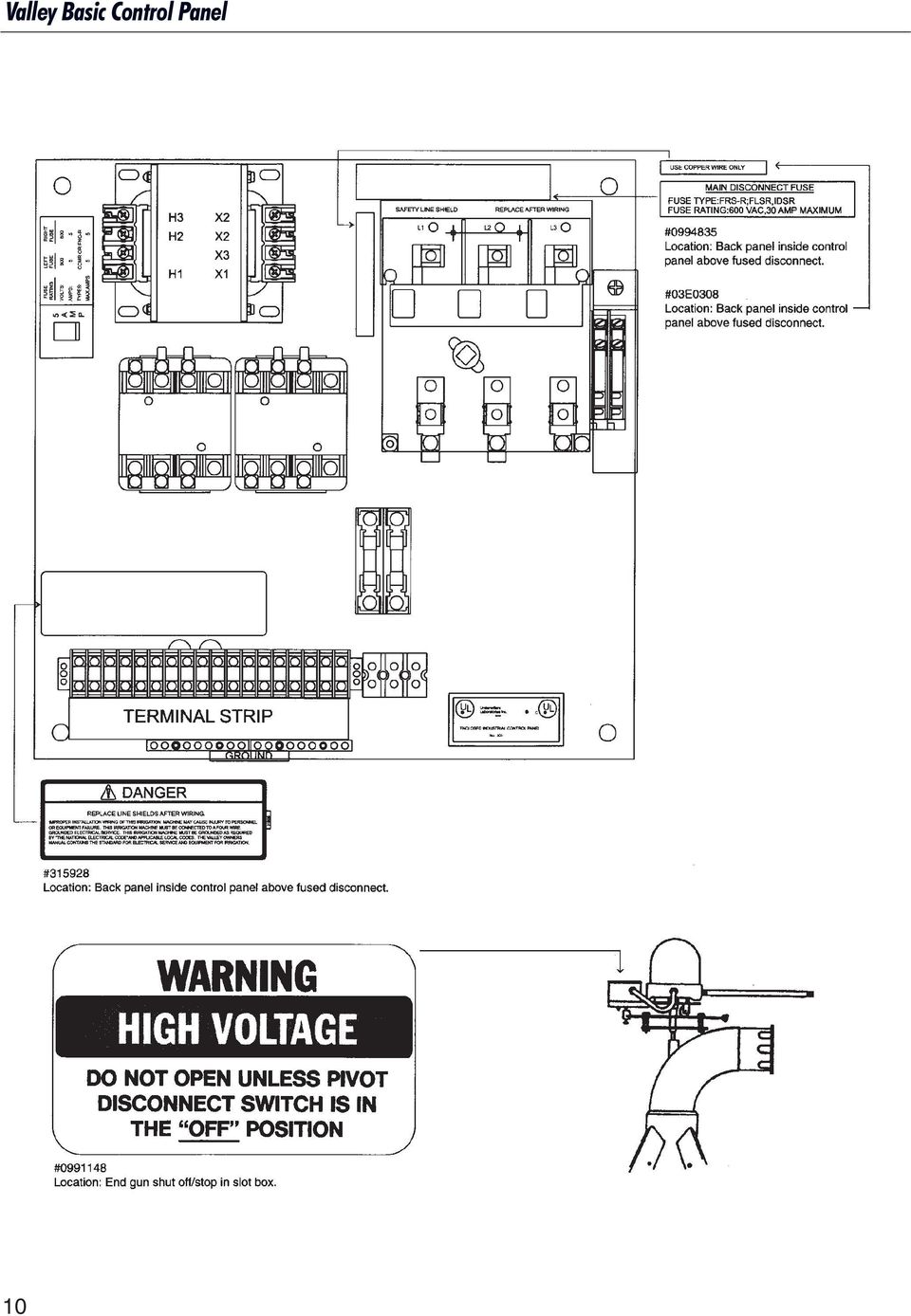
11 INTRODUCTION Congratulations on the purchase of your Valley center pivot irrigation system with the Valley Basic Control Panel. This panel has been designed for the operator with ease of use in mind. The large rocker switches and the easy to read percent timer, volt meter and hour meter all combine to give you the most user-friendly center pivot controls in the industry. The modular design of the controls also gives the user maximum flexibility from a serviceability standpoint. Enjoy your new purchase ABOUT THIS MANUAL This manual only covers the operation of the Valley Basic Control Panel. Sections related to safety, pivot hardware, maintenance, towing, troubleshooting, winterization and electrical standards are covered in The Valley Pivot System Owners Manual. You, as the owner/operator, should familiarize yourself with the capabilities of the system in order to obtain optimum system performance. It should be remembered that the sprinkler will perform according to your knowledge of the equipment, soil and water relationships and equipment application concepts. VALLEY BASIC PANEL CONTROLS/COMPONENTS DANGER: 480 VOLTS Do not open the interior control panel door. Electrical shock may occur. All needed controls and monitoring devices are on the outside of the interior control panel door. Service work done on the control panel is to be performed by a qualified service person only. Figure

12 MAIN DISCONNECT This switch disconnects all power to the system except at the incoming (upper) terminals on the Main Disconnect Switch inside the control panel. The function of the disconnect is to turn the power OFF when doing any maintenance or repairs and when the system is not in use. If Center Pivot safety circuit is complete, the machine will continue to run. To stop the machine, move the rocker switch to the STOP position. When the Start-Stop switch is placed and held in the START position, the Center Pivot safety circuit is bypassed This is why the rocker switch should never be held in the START position for more than three seconds at anyone time. ON OFF If, for some reason, the Center Pivot misaligns and the safety circuit is broken (open), it will be necessary to override the safety circuit momentarily to realign the machine. Figure SECOND AUTO RESTART A three second auto restart is standard equipment built into the circuitry of the Valley system. In the event of a momentary power loss or voltage drop, the system will automatically restart, if power is returned within three seconds. CAUTION TO REDUCE THE POSSIBLITY OF DAMAGE TO AN AUTOMATICALLY CONTROLLED ELECTRIC PUMP DUE TO A MOMENTARY POWER LOSS OF 3 SECONDS OR LESS, A PUMP RESTART DELAY IS REQUIRED IN THE PUMP CIRCUIT BETWEEN THE PIVOT CONTROL PANEL AND THE PUMP. START-STOP/SAFETY OVERRIDE START The Valley Basic Control Panel is equipped with a combination Start-Stop Safety Override rocker switch. Figure The Start-Stop rocker starts and stops the Center Pivot. To start the machine, the switch is moved from the STOP to the START position. The switch should be pressed and held in the START position for approximately three seconds and then released at which time the switch will return to a center neutral RUN position. CAUTION Caution must be taken by the operator when the Start- Stop rocker switch is held in the START positions. It will bypass or disable all the Center Pivot safety circuits NEVER hold the Start-Stop rocker in the START position for more than three to five seconds. If the machine is not in full view by the operator, it is not recommended the Start-Stop switch be held in the START position. NEVER hold the Start-Stop rocker in the START position for longer than three to five seconds. The operator MUST inspect the entire machine between each start attempt. Repeated safety override start attempts can cause severe structural damage. Call your local Valley dealer should the machine fail to start. SAFETY RETURN LIGHT The small light above the Start-Stop rocker switch is the Safety Return Light. When lit, it indicates that there is power going out to the end og the machine and coming back to the control panel on the center pivot return safety circuit. This indicator lamp will also light when the Start-Stop rocker switch is pressed to the start position. FORWARD/REVERSE Enables the operator to run the system in the forward (clockwise) or reverse (counter clockwise) direction assuming all safety circuits are complete. Figure 1.4 The direction of travel can be changed while the system is moving or selected before start-up.

13 WET/DRY By-passes the optional low pressure switch. The low pressure switch can be adjusted to close at a range of pressures. For example, the operator may choose to set the switch at 15 psi. When the water pressure at the switch location reaches 15 psi, the switch will close which completes the safety Figure 1.5 circuit and allows the system to run. Therefore, if the switch was in the WET position and the pressure dropped below 15 psi, the system would shut down, thus providing the operator a low pressure shutdown. However, if the operator wants to run the system dry (without water), the low pressure switch MUST be by-passed. This can be accomplished by setting the switch in the DRY position. The low pressure switch is then removed from the safety circuit and the system will run without water pressure. NOTE If the switch is left in the DRY position when the operator is applying water the system will NOT shut down if the pressure falls below the low pressure setting. NOTE The percentage timer determines the percentage of one minute which the end tower of the system will run, therefore, regulating the revolution time of the system. Refer to the system s sprinkler chart to provide water application amounts at different settings. The Percent Timer Setting Calculations section explains the calculation process for determining water applications at different percent timer settings. OPTIONS Options on the Valley Basic Control Panel include an AC Voltage Meter, Engine Run/Start, SIS On/Off and the Auxiliary On/Off rocker switches. VOLTAGE METER 460 Volts Minimum. 505 Volts Maximum. PERCENTAGE TIMER The percentage timer regulates the revolution time of the system. A C VOLTS Optimum Operating Voltage = 480 Volts AC. The amount of water which the operator applies is determined by setting the percentage timer. Figure 1.6 A percentage timer setting of 100 percent indicates the end tower of the system would move continuously, providing the shortest revolution time. One hundred percent is also the setting at which the minimum amount of water can be applied. If the percentage timer is set at 50 percent, the revolution time of the system and the water application amount is doubled. The end tower of the system would move for approximately 30 seconds out of each minute at a setting of 50%. Figure 1.8 The voltage meter displays the voltage being delivered to the system in the panel. The meter should read 460 to 505 volts during normal operation. NOTE Some long or high amperage systems may need to be run at 500 volts minimum. CAUTION DO NOT operate the system if the meter reads below 460 or above 505 volts. Operating the system outside these limits could cause damage to the electrical components. 480 volts AC is the recommended operating voltage. 13
, the low pressure switch MUST be by-passed. This can be accomplished by setting the switch in the DRY position.")
14 ENGINE RUN/START A standard engine RUN/START switch is installed for easy wiring of an engine shutdown circuit. If the switch is in the RUN position, the engine would shut down if the pivot system stops for some reason. Figure 1.8 The switch MUST be in the START position to start the engine. SIS ON/OFF Allows the optional stop-in-slot to be activated or by-passed. Stop-in-slot, stops the system at a preset location in the field (set by the operator) when the switch is in the ON position. Figure 1.9 Setting the switch in the OFF position by-passes stop-in-slot, so the system will NOT stop at the preset location. To set the stop location, refer to the End Gun Shut-Off and Stop In Slot Option section in The Valley Pivot System Owners Manual. AUXILIARY ON/OFF This optional switch is available for such uses as injector pump operation, manual end gun control or other options the operator may decide to install. Figure

15 PANEL OPERATION Starting The System Wet (With Water) 1) Inspect the wheel tracks to ensure there are no vehicles or other equipment which will obstruct the system upon start-up or operation. 2) Place the WET/DRY switch in the DRY position to by-pass the low pressure switch. 3) If an engine shutdown circuit is utilized, place the Engine RUN/START switch in the START position. 4) Partially close the mainline valve to the system. This will help to prevent water hammer if the pump is powered by an electric motor. 5) Start the pump. (The pump may be wired such that when the START switch on the center pivot control panel is pressed, the pump automatically starts. Check with your Valley dealer to determine how your pump has been wired into your pivot control panel.) 6) Slowly introduce more water into the system by either opening the mainline valve or by increasing the engine speed. Examine the Valley System s pressure gauge to ensure the desired operating pressure. 7) Turn the main disconnect switch to the ON position. If the power is supplied by an engine driven generator, adjust the RPM of the generator until the voltmeter reads volts. DO NOT EXCEED 505 VOLTS. 8) Place the WET/DRY switch in the WET position. 9) Select the direction of travel by placing the FORWARD/REVERSE switch in either the FORWARD or REVERSE position. Remember, Forward is clockwise and Reverse is counterclockwise. 10) Press the START-STOP switch to the START location for 1 2 seconds and release. The system should now start. 11) Place the Engine RUN/START switch in the RUN position. 12) Set the percentage timer to the desired speed setting. 13) If the system is equipped with the optional stopin-slot, place the SIS ON/OFF switch in the desired position. Starting The System Dry (Without Water) To operate the system DRY (without water), follow the previous Starting the System WET (With Water) procedure, eliminating steps 4, 5, 6 and 8. The WET/DRY switch must be in the DRY position. STARTING THE SYSTEM Figure

16 Stopping The System 1) Press the START-STOP switch to the STOP position. 2) Turn the main disconnect switch to the OFF position. 3) Turn the pumping unit OFF (if not automatic). 4) If an engine generator set is utilized, place the Engine Run/Start switch to the Start position for the next start-up sequence. WARNING DO NOT shut the system off by slowly idling down the engine-generator set. This practice causes low voltage and will damage system components. ALWAYS STOP the irrigation system prior to shutting down the engine-generator set. STOPPING THE SYSTEM 16

17 PERCENT TIMER SETTING CALCULATIONS The percent timer regulates the system speed which controls the amount of water being applied per revolution. A percent timer setting of 100% would indicate that the end tower moves continuously or 100% of the time. A percent timer setting of 50% would indicate that the end tower runs 50% of the time or 30 seconds out of each minute, therefore, doubling the amount of water being applied. A sprinkler chart like the one illustrated in figure 1.23 will provide the operator with the necessary information to determine water application depths and revolution times at different percent timer settings. INCHES PER PERCENT TIMER HOURS PER REVOLUTION SETTING REVOLUTION Figure If the system length, flow rate in GPM and revolution times are known, these values can be calculated as described in the following procedure. 1. Determine The System Length DLRDU OH EGR SL SL = Total System Length (feet) DLRDU = Distance to the Last Regular Drive Unit (feet) OH = Overhang Length (feet) EGR = End Gun Radius (feet) Approximate End Gun Radius Coverages SL = DLRDU + OH + EGR Example: DLRDU = 1260 OH Length = 64 EGR = 100 SL = SL = 1424 Rainbird 85 = 60 feet Rainbird 95 = 65 feet Nelson 100 = 100 feet Rainbird 103 = 100 feet 17

18 2. Determine the End Tower Rotational Speed at 100% Timer Setting from the following chart: Standard Tires Retread High Float Maxi-Float LRDU*** 11.2 x x x x x 38 Center Drive Output RPM ft./min. M/min. ft./min. M/min. ft./min. M/min. ft./min. M/min. ft./min. M/min *** RPM and speed for 480 V, 60 Hz service. For 50 Hz service reduce travel by factor of LRDU = Last Regular Drive Unit Example: 30 RPM center drive motor with 14.9 x 24 High Float Tires = 6.77 ft./min. 3. Determine Inches/Day the System will Apply Inches/Day = (GPM) (735.3) (SL) 2 Example: Assume GPM = 800 gpm SL = 1424 Inches/Day = (800) (735.3) (1424) 2 = 0.29 inches/day 4. Determine Hours/Revolution at 100 Percent Timer Setting Hours/Revolution = (.105) (DLRDU) (100%) nnn (Speed in ft./min.) Example: DLRDU = 1260 Speed in ft./min. = 6.77 ft./min. Hours/Revolution = (.105) (1260) (100%) nnn (6.77) = 19.5 Hours/Revolution at 100% 5. Determine Inches/Revolution at 100 Percent Timer Setting Inches/Revolution = (Hours/Revolution) (Inches/Day) (100%) nnn 24 Example: Hours/Revolution = 19.5 Inches/Day = 0.29 Inches/Revolution = (19.5) (.29) (100%) nnn = 24 = 0.24 Inches/Revolution at 100% 6. Determine Inches/Revolution and Hours/Revolution for any percent timer setting using these two formulas: Inches/Revolution = (Inches/Revolution at 100%) (100) (Percent Timer Setting) Example: Inches/Revolution = (0.24) (100) at 50%nnnnnnnnn (50) = 0.48 inches at 50% Hours/Revolution = (Hours/Revolution at 100%) (100) (Percent Timer Setting) Example: Hours/Revolution = (19.5) (100) at 50%nnnnnnnnn 50 = 39 Hours/Revolution at 50% 18
 (735.")
19 Percent Timer Setting Calculation Worksheet 1. Determine System Length SL = feet 2. Determine the End Tower Rotational Speed at 100% Timer Setting Speed = ft./min. 3. Determine Inches/Day the system will apply. Inches/Day = (GPM) (735.3) (SL) 2 = ( ) (735.3) ( ) 2 = ( ) ( ) = 4. Determine Hours/Revolution at 100 Percent Timer Setting Hours/Revolution = (.105) (DLRDU) (100%)nnnn (Speed in ft./min.) = (.105) ( ) ( ) = ( ) ( ) = 5. Determine Inches/Revolution at 100 Percent Timer Setting Inches/Revolution = (Hours/Revolution) (Inches/Day) (100%)nnnn 24 = ( ) ( ) 24 = ( ) 24 = 19
 (DLRDU) (100%)nnnn (Speed in ft./min.) = (.105) ( ) ( ) = ( ) ( ) = 5.")
20 6. Determine Inches/Revolution and Hours/Revolution for any percent timer setting using these two formulas: Inches/Revolution = (Inches/Revolution at 100%) (100) (Percent Timer Setting) = ( ) (100) ( ) = ( ) ( ) = 100% = ( ) Inches Per Revolution 90% = ( ) (.98) = In./Rev. 80% = ( ) (.88) = In./Rev. 70% = ( ) (.78) = In./Rev. 60% = ( ) (.68) = In./Rev. 50% = ( ) (.58) = In./Rev. 40% = ( ) (.48) = In./Rev. 30% = ( ) (.38) = In./Rev. 25% = ( ) (.25) = In./Rev. 20% = ( ) (.28) = In./Rev. 15% = ( ) (.15) = In./Rev. 10% = ( ) (.18) = In./Rev. 5% = ( ) (.05) = In./Rev. Hours/Revolution = (Hours/Revolution at 100%) (100) (Percent Timer Setting) = ( ) (100) ( ) = ( ) ( ) = 100% = ( ) Hours Per Revolution 90% = ( ) (.98) = Hrs./Rev. 80% = ( ) (.88) = Hrs./Rev. 70% = ( ) (.78) = Hrs./Rev. 60% = ( ) (.68) = Hrs./Rev. 50% = ( ) (.58) = Hrs./Rev. 40% = ( ) (.48) = Hrs./Rev. 30% = ( ) (.38) = Hrs./Rev. 25% = ( ) (.25) = Hrs./Rev. 20% = ( ) (.28) = Hrs./Rev. 15% = ( ) (.15) = Hrs./Rev. 10% = ( ) (.18) = Hrs./Rev. 5% = ( ) (.05) = Hrs./Rev. 20
 = Hrs./Rev. 80% = ( ) (.88) = Hrs./Rev. 70% = ( ) (.78) = Hrs./Rev. 60% = ( ) (.68) = Hrs./Rev. 50% = ( ) (.58) = Hrs./Rev. 40% = ( ) (.48) = Hrs./Rev. 30% = ( ) (.38) = Hrs./Rev. 25% = ( ) (.")
EPM3. Phase Sequence and Motor Rotation Tester. Users Manual
 EPM3 Phase Sequence and Motor Rotation Tester Users Manual 1 L1 L2 L3 2 3 A B C CAT 600V 3-PHASE TESTER 5 TEST M1 M2 BATT M3 EPM3 MOTOR ROTATION TESTER EPM3 MOTOR ROTATION DETERMINED WHILE FACING MOTOR
Operational Overview and Controls Guide. Two or Three Pump IronHeart Lite with Variable Frequency Drives
 DOCUMENT: ECSEQ6-0 EFFECTIVE: 09/23/10 SUPERSEDES: Operational Overview and Controls Guide Two or Three Pump IronHeart Lite with Variable Frequency Drives 6700 Best Friend Road. Norcross, GA 30071. (770)
CARING FOR YOUR WATER HEATER
 http://waterheatertimer.org/troubleshoot-rheem-tankless-water-heater.html Water Heater Inspections CARING FOR YOUR WATER HEATER Venting System (Direct Vent Only) The venting system should be inspected
Operational Overview and Controls Guide
 DOCUMENT: ECSEQ2-1 EFFECTIVE: 02/14/07 SUPERSEDES: 02/26/03 Operational Overview and Controls Guide Standard Two or Three Pump Type VFD Booster Controls 6700 Best Friend Road. Norcross, GA 30071. (770)
2010-13 Field Commander Wiring Manual
 2010-13 Field Commander Wiring Manual Section 1 Pages 2-4 BASIC / ENHANCED SERVICE: Pivot wiring NOT using start, theft monitoring, or direction control Section 2 Pages 5-9 PRO SERVICE: Pivot wiring using
7 FUNCTION DIGITAL MULTIMETER
 7 FUNCTION DIGITAL MULTIMETER 90899 OPERATING INSTRUCTIONS 3491 Mission Oaks Blvd., Camarillo, CA 93011 Visit our Web site at http://www.harborfreight.com Copyright 2004 by Harbor Freight Tools. All rights
TIG INVERTER INSTRUCTION MANUAL
 TIG INVERTER INSTRUCTION MANUAL Contents Warning General Description Block Diagram Main Parameters Circuit Diagram Installation and Operation Caution Maintenance Spare Parts List Troubleshooting 3 4 4
INSTALLATION INSTRUCTIONS & HOME OWNERS MANUAL EEMAX ELECTRIC TANKLESS WATER HEATERS IMPORTANT SAFETY INFORMATION
 INSTALLATION INSTRUCTIONS & HOME OWNERS MANUAL EEMAX ELECTRIC TANKLESS WATER HEATERS IMPORTANT SAFETY INFORMATION When installing or using any high voltage electrical appliance, basic safety precautions
Oil and Coolant Circulating Heating System. Model - OCSM
 Oil and Coolant Circulating Heating System Model - OCSM Installation & Operation Manual 216280-000 REV 2 Identifying Your System The HOTSTART heating system is designed to heat fluids for use in marine
CTV-1500 Cooling Tower Vacuum Operating & Maintenance Manual
 CTV-1500 Cooling Tower Vacuum Operating & Maintenance Manual Goodway Technologies Corporation 420 West Avenue Stamford, CT 06902-6384 (203)359-4708 Sales: 1-800-333-7467 Customer Service: 1-800-370-2855
IntelliBrite Controller (For IntelliBrite Pool, Spa and Landscape Lighting Fixtures) Installation and User s Guide
 Installation and User s Guide") IntelliBrite Controller (For IntelliBrite Pool, Spa and Landscape Lighting Fixtures) Installation and User s Guide *619751* P/N 619751 - Rev C IMPORTANT SAFETY INSTRUCTIONS READ AND FOLLOW ALL INSTRUCTIONS
IntelliBrite Controller (For IntelliBrite Pool, Spa and Landscape Lighting Fixtures) Installation and User s Guide *619751* P/N 619751 - Rev C IMPORTANT SAFETY INSTRUCTIONS READ AND FOLLOW ALL INSTRUCTIONS
Seven function digital multimeter
 Seven function digital multimeter 98025 Set up And Operating Instructions Distributed exclusively by Harbor Freight Tools. 3491 Mission Oaks Blvd., Camarillo, CA 93011 Visit our website at: http://www.harborfreight.com
MODEL T-4 TRENCHER. Operators Manual
 DO NOT THROW AWAY IMPORTANT MANUAL MODEL TRENCHER Operators Manual P.O.BOX 290 San Bernardino, CA. 92402 Phone (909) 478-5700 (800) 922-4680 Fax (909) 478-5710 E-mail: [email protected] www.groundhoginc.com
Chemigation Calibration for Center Pivot Irrigation Systems
 April 1993 (reformatted May 2000) Chemigation Calibration for Center Pivot Irrigation Systems A Workbook for Certified Pesticide Applicators To accompany the VHS tape Chemigation Calibration Based on materials
C3306 LOCKOUT/TAGOUT FOR AUTHORIZED EMPLOYEES. Leader s Guide. 2005, CLMI Training
 C3306 LOCKOUT/TAGOUT FOR AUTHORIZED EMPLOYEES Leader s Guide 2005, CLMI Training LOCKOUT/TAGOUT FOR AUTHORIZED EMPLOYEES This easy-to-use Leader s Guide is provided to assist in conducting a successful
cams Management Systems Technology focused on conserving energy Performance. Period.
 TM cams Management Systems Performance. Period. Technology focused on conserving energy 00 camstm Management Systems Providing Choices to meet your needs Durability and reliability Component continuity
REB 1 REB 3 REB 5 REB 6 REB 8 REB 10 REB 12 REB 16
 REB 1 REB 3 REB 5 REB 6 REB 8 REB 10 REB 12 REB 16 Manually Operated Electronic Speed Controller Single Phase For all applications using suitably specified single-phase induction motor fans 1 GENERAL The
15GAL STEEL OIL DRAIN WITH 110V PUMP
 15GAL STEEL OIL DRAIN WITH 110V PUMP OWNER S MANUAL WARNING: Read carefully and understand all ASSEMBLY AND OPERATION INSTRUCTIONS before operating. Failure to follow the safety rules and other basic safety
BWC Division of Safety and Hygiene
 BWC Division of Safety and Hygiene A SAMPLE LOCKOUT/TAGOUT PROCEDURE A good Lockout/Tagout Procedure, at a minimum, should contain the following elements: 1. All maintenance personnel shall be provided
Lockout / Tagout Program
 Lockout / Tagout Program Table of Contents Page Scope... 2 Definitions... 2 Authorization... 3 Responsibilities... 4 Compliance and Enforcement... 4 When to Lockout/Tagout (LOTO)... 5 Lockout Procedure...
Infrarot-Bewegungsmelder IP44
 Infrarot-Bewegungsmelder IP44 infrared motion sensors IP44 ODA (weiß) slim ODA (schwarz) slim 95174 96000 ODA (weiß) ODA (schwarz) 95175 96001 Betriebsanleitung User s Manual User s Manual infrared motion
3088 Lockout-Tagout Training Program Course Outline
 3088 Lockout-Tagout Training Program Course Outline The following outline summarizes the major points of information presented in the course. The outline can be used to review the course before conducting
Cisco TelePresence MCU 4500 Series safety and compliance information
 Cisco TelePresence MCU 4500 Series safety and compliance information On this page: Safety information symbols Operating guidelines Safety warnings Technical specifications Compliance information WEEE information
Model 1756 Test Lead Kit
 Keithley Instruments 28775 Aurora Road Cleveland, Ohio 44139 1-888-KEITHLEY http://www.keithley.com Model 1756 Test Lead Kit Gerneral Purpose Test Lead Information Description These test leads allow you
12-Volt 10-Amp Regulated Power Supply
 22-506.fm Page 1 Friday, August 6, 1999 12:55 PM Cat. No. 22-506 OWNER S MANUAL Please read before using this equipment. 12-Volt 10-Amp Regulated Power Supply 22-506.fm Page 2 Friday, August 6, 1999 12:55
Service manual. Website: www.andico.com.au CAUTION - BEFORE SERVICING THE UNIT, READ THE SAFETY - PRECAUTIONS IN THIS MANUAL.
 Website: www.andico.com.au Service manual CAUTION - BEFORE SERVICING THE UNIT, READ THE SAFETY - PRECAUTIONS IN THIS MANUAL. - ONLY FOR AUTHORISED SERVICE PERSONNEL. MODELS: MPK1-09CR-QB8 MPK1-12ER-QB6
Rexroth Hydraulic Pump A10VO Series User Manual
 Rexroth Hydraulic Pump A10VO Series User Manual Rexroth Hydraulic pump A10VO Series User Manual Revised 5/1/2009 Page 1 of 12 Functional Purpose This pump is preferred over a fixed displacement (gear)
SHHH AIR COMPRESSOR Model Nos. SHHH2 - SHHH2/9 - SHHH3/9 - SHH3/24
 SHHH AIR COMPRESSOR Model Nos. SHHH2 - SHHH2/9 - SHHH3/9 - SHH3/24 OPERATING & MAINTENANCE INSTRUCTIONS 1205 PARTS & SERVICE For Spare Parts and Service,please contact your nearest dealer, or CLARKE International,
Ceiling Mount Air Handler Manual
 www.surna.com 303.993.5271 Ceiling Mount Air Handler Manual Models: CMAH12, CMAH18, CMAH24, CMAH30, CMAH36, CMAH48, CMAH60 Revised: September 2014 Table of Contents Warranty Information 4 Limited Warranty
SERVICE MANUAL FOR 12 VDC WALL THERMOSTAT AIR CONDITIONING SYSTEMS ROOF TOP UNITS ONLY
 RV Products Division SERVICE MANUAL FOR 12 VDC WALL THERMOSTAT AIR CONDITIONING SYSTEMS ROOF TOP UNITS ONLY Airxcel, Inc. RV Products Division P.O. Box 4020 Wichita, KS 67204 1976A376 (1-11) TABLE OF CONTENTS
Owner s Manual & Safety Instructions
 Owner s Manual & Safety Instructions Save This Manual Keep this manual for the safety warnings and precautions, assembly, operating, inspection, maintenance and cleaning procedures. Write the product s
3053 Electrical Safety Training Program Course Outline
 3053 Electrical Safety Training Program Course Outline The following outline summarizes the major points of information presented in the program. The outline can be used to review the program before conducting
with MERCURY FREE 1 HP Relays ! WARNING Before using this product read and understand instructions.
 B Installation & Maintenance Instructions MM-414 Series 150E and 157E Low Water Cut-Off/Pump Controllers For Steam Boilers and Other Level Control Applications A Typical Applications: Primary or secondary
1000-LB. TRAILER JACK OWNER S MANUAL
 1000-LB. TRAILER JACK OWNER S MANUAL WARNING: Read carefully and understand all INSTRUCTIONS before operating. Failure to follow the safety rules and other basic safety precautions may result in serious
Mobile Equipment Safety
 Mobile Equipment Safety PLANNING THE JOB Hazard Assessment DO YOU HAVE THE RIGHT EQUIPMENT? ARE THERE HAZARDS TO BE AVOIDED? IS THE GROUND AREA STRONG ENOUGH TO SUPPORT THE EQUIPMENT? ARE THERE ANY UNUSUAL
PROFITEER POPCORN MACHINE SERVICE MANUAL
 3243 North California Avenue, Chicago, IL 60618 PROFITEER POPCORN MACHINE SERVICE MANUAL 120 Volt, Single Phase, 60 Hz 230 Volt, Single Phase, 50 Hz Included in this manual: *One Pop Option *Salt/Sugar
Single Phase Soft Starter
 Single Phase Soft Starter Installation & Operating Manual 6/02 Table of Contents Section 1 General Information................................................... 1 1 General Description................................................
Manual Ranging MultiMeter
 Owner s Manual Manual Ranging MultiMeter Model 82345 CAUTION: Read, understand and follow Safety Rules and Operating Instructions in this manual before using this product.! Safety! Operation! Maintenance!
19 LED Tube Controller ORDERCODE 41003
 19 LED Tube Controller ORDERCODE 41003 Congratulations! You have bought a great, innovative product from Showtec. The Showtec 19 LED Tube Controller brings excitement to any venue. Whether you want simple
SBC90. Abrasive Blast Cabinet Assembly & Operating Instructions
 SBC90 Abrasive Blast Cabinet Assembly & Operating Instructions READ ALL INSTRUCTIONS AND WARNINGS BEFORE USING THIS PRODUCT. SAVE THESE INSTRUCTIONS FOR FUTURE REFERENCE. This manual provides important
CDS TROUBLESHOOTING SECTION I. VACUUM. 1.0. Weak vacuum at wand. Gauge reads normal (10hg to 14hg)
") CDS TROUBLESHOOTING SECTION I. VACUUM 1.0. Weak vacuum at wand. Gauge reads normal (10hg to 14hg) 1.1. Clogged hoses or wand tube. Disconnect hoses and carefully check for an obstruction. 1.2. Excessive
CDS TROUBLESHOOTING SECTION I. VACUUM 1.0. Weak vacuum at wand. Gauge reads normal (10hg to 14hg) 1.1. Clogged hoses or wand tube. Disconnect hoses and carefully check for an obstruction. 1.2. Excessive
SUBJECT: How to wire a motor starter Number: AN-MC-004 Date Issued: 2/08/2005 Revision: Original
 SUBJECT: How to wire a motor starter Number: AN-MC-004 Date Issued: 2/08/2005 Revision: Original A motor starter is a combination of devices to allow an induction motor to start, run and stop according
The table below lists the symbols used on the Clamp and/or in this manual. Important Information. See manual.
 i800 AC Current Clamp Instruction Sheet Introduction The i800 AC Current Clamp, the Clamp, has been designed for use with multimeters, recorders, power analyzers, safety testers, etc., for accurate non-intrusive
ACCUMULATOR INSTALLATION
 7001-7 ACCUMULATOR INSTALLATION BRAKE ACCUMULATORS I 308L93 Rae 7-59710 Issued 6-93 Printed in U.S.A 7001-8 Removal ACCUMULATOR VALVE 1. Park the machine on a level surface and lower the. loader bucket
WEEKLY SAFETY MEETING All Euramax Subsidiaries LOCKOUT / TAGOUT. Safety Meeting Contents. Meeting Notice. Leaders Guide.
 Safety Meeting Contents Meeting Notice Leaders Guide Employee Handout Employee Quiz Meeting Sign-In Sheet Employee Puzzle PRIOR TO THE WEEKLY MEETING: - Post the meeting notice by the timeclock - Read
Union County Public Schools. Facilities Department. Electrical. Safe Work Practices
 1 Union County Public Schools Facilities Department Electrical Safe Work Practices 2 Purpose In accordance with OSHA Standards 1910.331-335, safety-related work practices shall be used by Union County
LOCK-OUT / TAG-OUT SAFETY TRAINING
 LOCK-OUT / TAG-OUT SAFETY TRAINING Introduction Welcome to Lock-out Tag-out Training "So I m on the job one day, doing some repair on a cutting machine.replacing a guide on the table. Pretty routine everything
************* OWNER'S MANUAL BAMF800/2 BAMF1250/2 BAMF1800/2 BAMF2200/2 BAMF2600/2 BAMF1200/4 BAMF1600/4 BAMF2000/1D BAMF4000/1D BAMF5500/1D
 ************* OWNER'S MANUAL BAMF800/2 BAMF1250/2 BAMF1800/2 BAMF2200/2 BAMF2600/2 BAMF1200/4 BAMF1600/4 BAMF2000/1D BAMF4000/1D BAMF5500/1D INTRODUCTION Power Acoustik amplifiers provide high-performance
! WARNING. McDonnell & Miller Installation & Maintenance Instructions MM-217(I) Series 150S and 157S (Snap Switch, All Models except 157S-RB-P)
 Series 150S and 157S (Snap Switch, All Models except 157S-RB-P)") Series 150S and 157S (Snap Switch, All Models except 157S-RB-P) Low Water Cut-Off/Pump Controllers For Steam Boilers and Other Level Control Applications McDonnell & Miller Installation & Maintenance Instructions
Series 150S and 157S (Snap Switch, All Models except 157S-RB-P) Low Water Cut-Off/Pump Controllers For Steam Boilers and Other Level Control Applications McDonnell & Miller Installation & Maintenance Instructions
Art.S001-S002 SOLAR MODULE WITH DELIVERY AND RETURN CONNECTIONS
 Art.S001-S002 SOLAR MODULE WITH DELIVERY AND RETURN CONNECTIONS Technical Information sheet 0001/07/Rev01 ENG FUNCTION Series S001 and S002 circulation units are applied to the primary circuit of solar
OPL BASIC. Dosing System for Professional Laundry machines. Contents
 OPL BASIC Dosing System for Professional Laundry machines Contents 1 Getting Started. Page 2 2 Installation. Page 4 3 Set Up & Operation. Page 8 4 Maintenance & Accessories. Page 10 5 Troubleshooting Page
8 716 473 216-00.3O. Gas boiler. Gaz 6000 W WBN 6000-30-H-E-N/L-S2400. Operating instructions for the end customer. 8 716 473 217 (2014/07) en
 en") 8 716 473 216-00.3O Gas boiler WBN 6000-30-H-E-N/L-S2400 Operating instructions for the end customer en 2 Contents Contents 1 Key to symbols and safety instructions................... 2 1.1 Key to symbols..................................
8 716 473 216-00.3O Gas boiler WBN 6000-30-H-E-N/L-S2400 Operating instructions for the end customer en 2 Contents Contents 1 Key to symbols and safety instructions................... 2 1.1 Key to symbols..................................
SWIMMING POOL HEAT PUMP
 SWIMMING POOL HEAT PUMP Installation & User Manual Model HP40B HP50B HP65B Hayward Pool Products Canada, Inc. T: 1-888-238-7665 www.haywardpool.ca CONTENT I. Application 4 II. Features 4 III. Technical
INTRODUCTION WARNING S!!! VOC SHOULD BE BETWEEN 78 95. MUST NOT EXCEED 96 VOC USE DC CIRCUIT BREAKER/ISOLATOR BETWEEN SOLAR PANELS & CONTROLLER
 INTRODUCTION Thank you for purchasing a WATERBOY pumping system. We set the standard for quality and economy in solar pumping. The WATERBOY range incorporates the best solar pump technologies that were
ClearView 100. Instruction Manual
 ClearView 100 Instruction Manual Important Safeguards This appliance is not intended for use by children or infirm persons without supervision. Young children should be supervised to ensure that they do
section 5 machine guarding and lockout
 section machine guarding and lockout This section covers ways to physically protect people working in and around machinery. It includes information on: machinery guards lockout systems emergency stop confined
Control of Hazardous Energy LOCKOUT/TAGOUT 29 CFR 1910.147
 Control of Hazardous Energy LOCKOUT/TAGOUT 29 CFR 1910.147 Contents I. Introduction II. Scope and Application III. Definitions IV. Lockout/Tagout Manual V. Energy Control Procedures 1. Applying Energy
INDUSTRY WIDE LABOR-MANAGEMENT SAFETY COMMITTEE SAFETY BULLETIN #23
 INDUSTRY WIDE LABOR-MANAGEMENT SAFETY COMMITTEE SAFETY BULLETIN #23 GUIDELINES FOR WORKING WITH PORTABLE POWER DISTRIBUTION SYSTEMS AND OTHER ELECTRICAL EQUIPMENT "ADDENDUM C" WORKING WITH 480 VOLT SYSTEMS
Basic Operators Manual. Basic Pivot Center Operator s Manual
 Basic Operators Manual Basic Pivot Center Operator s Manual Basic Center Pivot Operator s Manual equipped with P/N 117764 Revision D 12/12 Our mission... to exceed our customers' expectations of quality,
Sport Ice Elektro 124
 Sport Ice Elektro 124 Operation Manual 2007/4 V2.1 Introduction The Sport Ice Elektro 124 is an ice resurfacing machine designed to be used on small ice surfaces. The machine has been designed to produce
ENGLISH INSTRUCTION & INSTALLATION MANUAL DUCTLESS MINI SPLIT AIR CONDITIONING SYSTEMS
 ENGLISH INSTRUCTION & INSTALLATION MANUAL DUCTLESS MINI SPLIT AIR CONDITIONING SYSTEMS Céliera Corporation. All rights reserved. Unauthorized duplication, reproduction prohibited. CONTENTS SAFETY PRECAUTIONS...
SERVICE MANUAL 12VDC WALL THERMOSTAT AIR CONDITIONING SYSTEMS ROOFTOP UNITS ONLY
 SERVICE MANUAL 12VDC WALL THERMOSTAT AIR CONDITIONING SYSTEMS ROOFTOP UNITS ONLY! WARNING - SHOCK HAZARD! TO PREVENT THE POSSIBILITY OF SEVERE PERSONAL INJURY, DEATH, OR EQUIPMENT DAMAGE DUE TO ELECTRICAL
OPERATOR S MANUAL 18 VOLT, 1 HOUR CHARGER
 OPERATOR S MANUAL 18 VOLT, 1 HOUR CHARGER P110 Your battery charger has been engineered and manufactured to Ryobi s high standard for dependability, ease of operation, and operator safety. When properly
PART 1 - INTRODUCTION...
 Table of Contents PART 1 - INTRODUCTION... 3 1.1 General... 3 1.2 Sensor Features... 3 1.3 Sensor Specifications (CDE-45P)... 4 Figure 1-1 CDE-45P Sensor Dimensions (standard, convertible style)... 4 PART
IMPORTANT SAFETY INSTRUCTIONS WARNING READ AND SAVE THESE OPERATING AND SAFETY INSTRUCTIONS BEFORE USING THIS HEATER.
 THERMAWAVE CERAMIC HEATER Model HZ-850 Series Model HZ-860 Series IMPORTANT SAFETY INSTRUCTIONS WARNING READ AND SAVE THESE OPERATING AND SAFETY INSTRUCTIONS BEFORE USING THIS HEATER. Warning Failure to
Instructions For SF 6 Refill Kit
 S&C Vista Underground Distribution Switchgear UnderCover, Vault-Mounted, and Pad-Mounted Styles Instructions For SF 6 Refill Kit TABLE OF CONTENTS Section Page Section Page INTRODUCTION..................................
FIREFIGHTER SAFETY. Stay safe during substation fires
 FIREFIGHTER SAFETY Stay safe during substation fires FIREFIGHTERS AND SUBSTATIONS Electrical substations reduce the high voltages used to move electricity over long distances to the lower voltages that
Troubleshooting Guide, Freedom and Fleet Power Inverter/Chargers
 Technical Note Freedom/Fleet Power 512-0084-01-01 Rev 1 Troubleshooting Guide, Freedom and Fleet Power Inverter/Chargers Overview This document is a guide for troubleshooting inverters, battery chargers,
Owner s Manual. For Automatic Transfer Switch. 100-200 Amp, Service Entrance/Non-Service Entrance
 Owner s Manual For Automatic Transfer Switch 100-200 Amp, Service Entrance/Non-Service Entrance Model Numbers RTST100A3 RTSP100A3 RTST150A3 RTST200A3 RTSP200A3 MODEL NUMBER: SERIAL NUMBER: DATE PURCHASED:
Electronically Controlled Air Suspension (ECAS) for Trucks
 for Trucks") $2.50 Electronically Controlled Air Suspension (ECAS) for Trucks Maintenance Manual No. 36 Issued 7-99 ECAS System for 6 x 2 and 6 x 4 Vehicles with Rear Air Suspensions Service Notes Service Notes This
$2.50 Electronically Controlled Air Suspension (ECAS) for Trucks Maintenance Manual No. 36 Issued 7-99 ECAS System for 6 x 2 and 6 x 4 Vehicles with Rear Air Suspensions Service Notes Service Notes This
Electronic Brake Controller Hayes Brake Controller Company ENERGIZE III P/N # 81741B or ENERGIZE XPC P/N #81745 OPERATION MANUAL
 Electronic Brake Controller Hayes Brake Controller Company ENERGIZE III P/N # 81741B or ENERGIZE XPC P/N #81745 OPERATION MANUAL ENERGIZE III is for trailers with 2 or 4 electric brakes and vehicles with
Department of Environmental Health & Safety. Lock Out/Tag Out Program. Date Effective: November 2010
 Department of Environmental Health & Safety Lock Out/Tag Out Program Issued by: Jeff Campbell Date Effective: November 2010 Date Revised: April 2014 General Policy Ohio University Lockout/Tagout Policy
MBSAW. Meat Cutting Band Saw With Meat Grinder Assembly & Operating Instructions
 06/2011 MBSAW Meat Cutting Band Saw With Meat Grinder Assembly & Operating Instructions READ ALL INSTRUCTIONS AND WARNINGS BEFORE USING THIS PRODUCT. This manual provides important information on proper
Lockout - Tagout. Control of Hazardous Energy OSHA Standard 1910.147
 Lockout - Tagout Control of Hazardous Energy OSHA Standard 1910.147 You will learn Purpose of Lockout-Tagout Requirements for LOTO Types of Hazardous Energy Procedures for LOTO Types of Energy Electrical
NUGGET GOLDRUSH PLUS T-2000 POPCORN MACHINES SERVICE MANUAL
 3243 North California Avenue, Chicago, IL 60618 Included in this manual: *One Pop Option *Salt/Sugar Option NUGGET GOLDRUSH PLUS T-2000 POPCORN MACHINES SERVICE MANUAL 120 Volt Single Phase, 60 Cycle 100/120
Signature and ISX CM870 Electronics
 Signature and ISX CM870 Electronics Cummins West Training Center System Description General Information The Signature and ISX CM870 engine control system is an electronically operated fuel control system
AWWA Butterfly Valve Operation and Maintenance Manual Series 511A & 510A 20 and Smaller
 January 2013 AWWA Butterfly Valve Operation and Maintenance Manual Series 511A & 510A 20 and Smaller Milliken Valve Company 190 Brodhead Avenue, Suite 100 Bethlehem, PA 18017 Phone: (610) 861-8803 Fax:
Max primary circuit temperature 90ºC Max primary circuit temp. 90ºC Max secondary circuit temperature 45ºC Max secondary circuit temp.
 EGLISH 1 Product description exchanger equipped with an electronic control unit and circulation pump for the primary circuit. All Aqua-Mex variants can be ordered with an interior coil of either titanium
CONTROL PANEL INSTALLATION INSTRUCTIONS. Single Phase Simplex Page 2-7. 3-Phase Simplex Page 8-13
 CONTROL PANEL INSTALLATION INSTRUCTIONS Single Phase Simplex Page 2-7 3-Phase Simplex Page 8-13 Single Phase Simplex SXL21=3, SXL24=3, SXH21=3, and SXH24=3 Manufactured by SJE-Rhombus Installation Instructions
NOTE: Additional user information for your printer may be available in the "Manuals" section at support.dell.com.
 CAUTION: General Safety Instructions Use the following safety guidelines to help ensure your own personal safety and to help protect your equipment and working environment from potential damage. NOTE:
TOYOTA ELECTRONIC TRANSMISSION CHECKS & DIAGNOSIS
 Checks and Adjustments The transmission requires regular maintenance intervals if it is to continue to operate without failure. As we discussed in previous sections, transmission fluid loses certain properties
Multi-Pitch Pitching Machine USER MANUAL
 Multi-Pitch Pitching Machine USER MANUAL TABLE OF CONTENTS Thank you for purchasing the Cimarron Multi-Pitch Pitching Machine. The Cimarron Multi-Pitch Pitching Machine is a high performance pitching machine
PTO OWNER S MANUAL ALLISON FAMILY CODE. pag.1
 PTO OWNER S MANUAL FAMILY CODE ALLISON pag.1 CONTENTS GENERAL INFORMATION Safety information...3 OMFB P.T.O. Safety Label Instructions...6 Foreword...7 INSTALLATION INSTRUCTIONS Mounting the PTO on the
Air Conditioner Water Heater - A Product of HotSpot Energy LLC
 Air Conditioner Water Heater - A Product of HotSpot Energy LLC PLEASE READ THIS BEFORE YOU INSTALL THE UNIT 1. This air conditioner must be installed and/or repaired by a qualified technician. If you perform
National- Spencer Inc.
 9-27-2010 National- Spencer Inc. 19.2V HEAVY DUTY GREASE GUN PRODUCT SPECIFICATION Charger Input Power 110 VAC Battery Output Power 19.2V Battery Capacity 1500 MAH Battery Pack Charge Time 1 Hour Maximum
Video Camera Installation Guide
 Video Camera Installation Guide The intent of this guide is to provide the information needed to complete or modify a video camera installation to avoid lightning and induced power surge damage. This guide
VX 2400 Dimmer User's Manual
 TM VX 2400 Dimmer User's Manual 21-2119C Manual Revision 1.01 Software Version 1.0 10 March 1994 Table of Contents 1. General Description...3 1.1. Standard Features:...3 2. Installing Options...4 2.1.
12 Volt 30 Amp Digital Solar Charge Controller
 12 Volt 30 Amp Digital Solar Charge Controller User s Manual WARNING Read carefully and understand all INSTRUCTIONS before operating. Failure to follow the safety rules and other basic safety precautions
FASCINATION 700 HVLP TANNING PRO SYSTEM USER MANUAL
 FASCINATION 700 HVLP TANNING PRO SYSTEM USER MANUAL Congratulations on choosing the Fascination 700 HVLP Tanning Pro System! Your system includes the following items: 1 Fascination 700 HVLP Tanning Pro
Series 30000 Hose Reels
 Operating Instructions and Parts List for Series 30000 Hose Reels - MANUAL DRIVEN - - POWER DRIVEN - SAFETY PRECAUTIONS Personal injury and/or equipment damage may result if proper safety precautions are
ALVERNIA UNIVERSITY OSHA REGULATION: 29 CFR 1910.147 THE CONTROL OF HAZARDOUS ENERGY (LOCKOUT / TAGOUT) SECTION: 2400
 SECTION: 2400") OSHA REGULATION: 29 CFR 90.7 THE CONTROL OF HAZARDOUS ENERGY (LOCKOUT / TAGOUT) DATE: 0/5/2008 DATE: /2/202 A. POLICY. This procedure follows requirements set forth in 29 CFR 90.7. 2. It is the policy
OSHA REGULATION: 29 CFR 90.7 THE CONTROL OF HAZARDOUS ENERGY (LOCKOUT / TAGOUT) DATE: 0/5/2008 DATE: /2/202 A. POLICY. This procedure follows requirements set forth in 29 CFR 90.7. 2. It is the policy
BC-5000 OPERATIONS MANUAL BATTERY CAPACITY TESTER COFKO LLC.
 BC-5000 BATTERY CAPACITY TESTER OPERATIONS MANUAL COFKO LLC. COPYRIGHT 2010 1 UNPACKING As you unpack your new BC-5000 battery capacity tester, inspect the tester for signs of shipping damage. If shipping
How To Size A Stenner Pump
 Metering Pumps Manufactured Since 1957 PCM Series Pump Control Module INSTALLATION AND MAINTENANCE MANUAL Table of Contents WarrantyandServicePolicy...3 Safety Information...............................................
6/14/02 Chapter 14: Use of Electrical Test Equipment 1/20
 USE OF ELECTRICAL TEST EQUIPMENT Test equipment is necessary for determining proper set-up, adjustment, operation, and maintenance of electrical systems and control panels. The following is a general procedure
ELECTRICAL SAFETY. The standard unit for measuring electrical current.
 ELECTRICAL SAFETY Introduction The following sections provide general safety guidelines and procedures for electrical safety. This chapter covers the following topics: TOPIC PAGE General Electrical Safety
POWER TRIM 5 F AUTO TRIM AND AUTO TRIM
 POWER TRIM 5 F 22217 AUTO TRIM AND AUTO TRIM Table of Contents Page Auto Trim System........................ 5F-1 Description........................... 5F-1 Auto Trim Operation...................... 5F-2
26 3213.13 Diesel Engine Driven Generators Page 1 of 6
 Last Update: December 8, 2014 A. Description of System Consultant s Handbook Page 1 of 6 1. Provide a diesel engine driven electric generating unit, factory assembled, tested and certified to operate at
8" BENCH GRINDER OWNER'S MANUAL
 8" BENCH GRINDER OWNER'S MANUAL WARNING: Read carefully and understand all INSTRUCTIONS before operating. Failure to follow the safety rules and other basic safety precautions may result in serious personal
ABB Drives. User s Manual. Pulse Encoder Interface Module RTAC-01
 ABB Drives User s Manual Pulse Encoder Interface Module RTAC-0 Pulse Encoder Interface Module RTAC-0 User s Manual 3AFE 64486853 REV A EN EFFECTIVE:.5.00 00 ABB Oy. All Rights Reserved. Safety instructions
ARCO Electric Products Installation and Maintenance Manual Low Voltage Automatic Power Factor Correction Capacitor Systems 2013
 ARCO Electric Products Installation and Maintenance Manual Low Voltage Automatic Power Factor Correction Capacitor Systems 2013 READ CAREFULLY These instructions are intended to cover good practices in