Modbus Protocol COMMUNICATIONS MANUAL. For Series 2 Laureate Digital Panel Meters, Counters, Timers & DIN-Rail Transmitters Now with Ethernet
|
|
|
- Dwain Ellis
- 7 years ago
- Views:
Transcription
1 Modbus Protocol COMMUNICATIONS NUAL For Series 2 Laureate Digital Panel Meters, Counters, Timers & DIN-Rail Transmitters Now with Ethernet LAUREL Electronics Inc G Airway Ave, Costa Mesa, CA, 92626, USA Tel: (714) Fax: (714) Website: -1-
 434-6131")
2 1. TABLE OF CONTENTS 1. TABLE OF CONTENTS INTRODUCTION, MODBUS PROTOCOL MODBUS CONNECTION EXAMPLES JUMPER SETTINGS & FIELD WIRING PROGMMING YOUR MODBUS DEVICE MODBUS PROTOCOL IMPLEMENTATION General Framing Electrical Interface Parameters Selectable via Instrument Setup (IS) Software Parameters Selectable via Front Panel Meter Setup Supported Function Codes Register Numbers vs. Meter Addresses Supported Exception Response Codes Message Formatting Message Examples for Device Address= 01, No Parity Data Types Internal Registers DPM & Analog Input Transmitter Internal Register Addresses Counter / Timer Internal Register Addresses WARNTY

3 2. INTRODUCTION, MODBUS PROTOCOL The Modbus Protocol is an industry-standard communications protocol that is selectable with all our serial communications signal options: Ethernet, USB, RS485 and RS232. It is implemented by the microcomputer on the main board and is compliant with Modbus RTU or ASCII transmission modes (software selectable), as specified in Modbus over Serial Line Specification V1.0 (2002). Digital panel meters, counters and timers require a plug-in option board for Modbus communications. This board can be any of the following: RS232 board RS485 board with dual RJ11 jacks. RS485 Modbus board with dual RJ45 jacks USB board USB-to-RS485 converter board Ethernet board Ethernet-to-RS485 converter board Our RS485 and Modbus RS485 boards are both Modbus compliant, but the RS485 board uses RJ11 jacks while the Modbus board uses RJ45 jacks as recommended in the Modbus Specification. With either board, the two jacks are wired in parallel to allow daisy chaining of meters with no need for a hub. Our USB-to-RS485 and Ethernet-to-RS485 converter boards allow the host meter to function as a normal meter, be connected to a host computer or Ethernet local area network (LAN), and also act as the device server for an RS485 network with up to 31 other meters equipped with an RS485 board. These meters can then be daisy-chained using readily available, straight-through 6-wire data cables (not 4-wire telephone cables or crossover cables). Use repeaters to increase the number of addressable meters. Our DIN-rail transmitters come with a user-selectable Ethernet or RS232/RS485 I/O port in addition to a scalable 4-20 ma output, which is standard. Our DIN-rail Ethernet-to-RS485 device server provides an RJ45 jack for connection to the Ethernet, an RJ11 jack to support an RS485 network of meters, plus screw terminals to support an RS485 network of DIN-rail transmitters via a set of 3 or 5 parallel wires (half- or full-duplex). The Modbus TCP protocol is seamlessly converted by our Ethernet Nodes to Modbus RTU or Modbus ASCII for communication with meters and transmitters on an RS485 bus. Please see our Ethernet Manual for more information. The Custom ASCII Protocol is a software-selectable alternative to the Modbus Protocol. It also allows device addressing of up to 31 devices. It is less complex than the Modbus protocol, but is limited to use with our devices. Please see our Custom ASCII Protocol Communications Manual
. Digital panel meters, counters and timers require a plug-in option board for Modbus communications. This board can be any of the following: RS232 board RS485 board with dual RJ11 jacks.")
4 3. MODBUS CONNECTION EXAMPLESS - 4 -
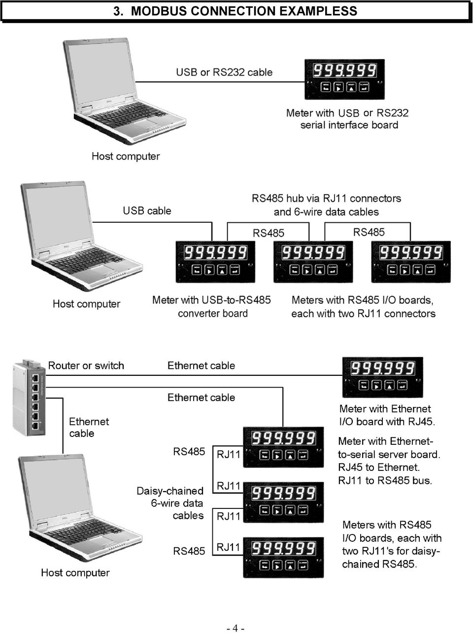
5 With an Ethernet connection, our Nodes and the host PC can be connected directly to the same LAN, and our software will automatically discover all our Nodes in the LAN. A Node cannot be connected directly to a PC via an Ethernet cable. For connection via the Internet, the PC can be plugged into a local LAN, and the remote instruments can be plugged into a remote LAN. Laureate Ethernet Nodes and any Devices attached to them via an RS485 bus are automatically discovered by our Ethernet software when the IP address of the remote router is supplied. Laurel software can be our Node Manager Software, Instrument Setup Software, or XLOG Datalogging Software. 4. JUMPER SETTINGS & FIELD WIRING 1. SAFETY WARNINGS Digital panel meters, counters, timers and transmitters may be powered with AC (mains) from Vac or Vdc with standard high voltage power, or 12-34V ac or Vdc with the low voltage power supply option. To avoid the possibility of electrical shock or damaging short circuits, always unplug the device before opening the case. Please refer to the respective device manuals for full safety information and instruction on how to open the case. Signal wiring changes external to the case can be made safely while the units are under power. 2. JUMPERS ON SERIAL METER BOARDS - 5 -

6 USB Board & Basic Ethernet Board No jumpers needed. RS232 Board e - Externally enabled RTS (otherwise always enabled) f - Remote display (or slave) operation. g - Normal operation (other than remote display). Note: Board is shipped with jumper g installed. RS485-Modbus Board, Full Duplex Operation b & e - Bias jumpers should be installed on 1 board. a & d - Installed on last meter in long cable run. RS485-Modbus Board, Half Duplex Operation a d c b e f RJ45 b & e - bias jumpers installed on 1 board. c & f - installed for half duplex operation. a - installed on last meter in line with long cable runs. Modbus RJ45 Note: Board is shipped with no jumpers installed. RS485 Board, Full Duplex Operation b & d - Installed on last meter in long cable run. RS485 Board, Half Duplex Operation a & c - Installed for half duplex operation. d - Installed on last meter in line with long cable runs. Note: Board is shipped with no jumpers installed. Ethernet-to-RS485 Converter Board & USB-to-RS485 Converter Board Full Duplex Operation No jumpers for short cable runs. Add b & d for long cable runs. Half Duplex Operation a & c for short cable runs. d - Installed on last meter in line with long cable runs. 3. CONNECTOR WIRING, SERIAL BOARD TO COMPUTER - 6 -

7 4. TNSMITTER CONNECTOR WIRING See below for different signal types Analog out - 1 Analog out + 2 AL2 1 AL2 2 AL1 3 AL1 4 P6 Signal input & excitation output P4 Analog output P3 Solid state relays Signal conditioner board P2 Serial data I/O P1 Power input RS485 RS232 6 N/C TX 5 ARX RX 4 ATX NC 3 GND GND 2 BRX GND 1 BTX N/C 3 Power GND 2 AC neutral or -DC 1 AC high or +DC RS232 cable with rear view of DB9 connector to PC - 7 -

8 a b E4 d c b a E6 * The termination resistor jumper settings should only be selected if the transmitter is the last device on an RS485 line longer than 200 feet (60 m). E1 E2 E3 a b d c c b a ** Or jumper external BTX to BRX and ATX to ARX (same effect as internal jumpers). Serial Signal Duplex Jumpers Termination Resistor* RS485 Full None E6 a = Transmit E6 c = Receive Half E6 b + d** E6 c RS232 Full None None Serial Signal Duplex Jumpers Termination Resistor* RS485 Full None E6 a = Transmit E6 c = Receive Half E6 b + d** E6 c RS232 Full None None * The termination resistor jumper settings should only be selected if the transmitter is the last device on an RS485 line longer than 200 feet (60 m). ** Attempting to draw more than the rated current will shut down the output. To reset communications to 9600 baud, command mode, Custom ASCII protocol, and Address 1, place a jumper at E1 and power up the transmitter. Analog Output Current Voltage Jumpers E2 a + d E2 b + c Excitation Output* Jumpers 5V, 100 ma E3 a + c; E4 a 10V, 120 ma E3 a + c; E4 b 24V, 50 ma E3 b, E4 none - 8 -

9 5. PROGMMING YOUR MODBUS DEVICE OVERVIEW Modbus digital panel meters, counters, timers and transmitters are easily programmed via their serial port using Windows-based Instrument Setup (IS) software, which provides a graphical user interface and is available at no charge. This software allows uploading, editing, downloading and saving of setup data, execution of commands under computer control, listing, plotting and graphing of data, and computer prompted calibration. Digital panel meters, counters and timers can also be programmed via their 4-key front panel as explained in their respective manuals; however, online programming is easier. For Ethernet, please see our separate Ethernet Manual. GETTING STARTED WITH INSTRUMENT SETUP SOFTWARE To install IS software, download the file instrument.exe from our website, double-click on the file name to extract three files, double-click on setup.exe, and follow the prompts. To launch IS software, press Start => Programs => IS2 => IS2. Establish communications by selecting matching settings between the instrument and PC, and click on Establish. Once communications have been established, click on Main Menu. The best way to learn IS software is to experiment with it. From the Main Menu, click on Get Setup to retrieve (or get) the existing setup data from your device. Click on View = > Setup to bring up screens which allow you to edit the setup file using pull-down menus and other selection tools. You can save your file to disk by clicking on File = > Save Setup. You can download (or put) your edited file into the device by clicking on Put Setup. Programmable items will only be displayed if the appropriate hardware has been detected, such as the dual relay option for meters. Pressing the F1 key at any time will bring up detailed help information. An analog output is defined in two steps. The input to the device is first scaled to a digital reading in engineering units, and this reading is then scaled to the analog output. The digital reading is also used for setpoint control and can be transmitted as serial data. ADDITIONAL FEATURES The Commands pull-down menu allows you to execute certain functions by using your computer mouse. The Commands pull-down menu will be grayed out unless a Get Setup has been executed. The Readings pull-down menu provides three formats to display input data on your PC monitor. In all formats, use the Pause and Continue buttons to control the timing of data collection, then press Print for a hardcopy on your PC printer. List presents the latest digital readings in a 20-row by 10-column table. Plot generates a plot of digital readings vs. time in seconds, like an oscilloscope. Graph generates a histogram, where the horizontal axis is the reading and the vertical axis is the number of readings

10 6. MODBUS PROTOCOL IMPLEMENTATION 1. GENEL The Modbus capability conforms to the Modbus over Serial Line Specification & Implementation guide, V1.0. Both the Modbus RTU and Modbus ASCII protocols are implemented: Modbus RTU Baud Rate , 600, 1200, 2400, 4800, 9600 or Data Format start bit, 8 data bits, 1 parity bit, 1 stop bit (11 bits total) Parity None, Odd, Even (if None, then 2 Stop bits for 11 total) Address for broadcast, for individual meters Modbus ASCII Baud Rate , 600, 1200, 2400, 4800, 9600 or Data Format Start bit, 7 Data bits, 1 Parity bit, 1 Stop bit (10 bits total) Parity None, Odd, Even (if None, then 2 Stop bits for 10 total) Address for broadcast, for individual meters 2. FMING Modbus RTU Message frames are separated by a silent interval of at least 3.5 character times. If a silent interval of more than 1.5 character times occurs between two characters of the message frame, the message frame is considered incomplete and is discarded. Frame Check = 16 bit CRC of the complete message excluding CRC characters. Modbus ASCII The message begins immediately following a colon (:) and ends just before a Carriage Return/ Line Feed (CRLF). All message characters are hexadecimal 0-9, A-F (ASCII coded). The system allowable time interval between characters may be set to 1, 3, 5 or 10 seconds. Frame Check = 1 byte (2 hexadecimal characters) LRC of the message excluding the initial colon (:) and trailing LRC and CRLF characters. 3. ELECTRICAL INTERFACE Four-wire (plus common) full-duplex or two-wire (plus common) half-duplex RS485 signal levels are jumper selectable for digital panel meters, counters and timers. A polarization resistor and termination resistor are also jumper selectable. In case of a long line (greater then 500 ft) to the first device, a termination resistor should be selected for the first device. In case of a long line length (greater then 500 ft) between the first and last devices, a termination resistor should be selected for the first and last devices. Never add termination resistors to more than two devices on the same line. A two-wire, half-duplex RS485 signal level is jumper selectable for transmitters

11 4. PAMETERS SELECTABLE VIA INSTRUMENT SETUP (IS) SOFTWARE Serial Protocol... Custom ASCII, Modbus RTU, Modbus ASCII Modbus ASCII Gap Timeout... 1 sec, 3 sec, 5 sec, 10 sec Baud Rate...300, 600, 1200, 2400, 4800, 9600, Parity... No parity, 2 stop bits; odd parity,1 stop bit; even parity, 1 stop bit Device Address... 0 to PAMETERS SELECTABLE VIA FRONT PANEL METER SETUP The two menu items related specifically to Modbus setup are SEr_4 and Addr. SEr_4 Serial Comm Modbus ASCII Gap Timeout 000 Serial Protocol 000 Parity 0 1 Sec 2 5 Sec 1 3 Sec 3 10 Sec 0 Customl ASCII (Non-Modbus) 1 Modbus RTU 2 Modbus ASCII 0 No Parity, 2 or more stop bits 1 Odd Parity, 1 or more stop bits 2 Even Parity, 1 or more stop bits Addr 000 Meter Address Set to desired address The baud rate is set in SEr_1 per the Meter manual. The selection of Modbus RTU or Modbus ASCII in SEr_4 above overrides any LF or Command Mode selections that have been made, since they are determined by the Modbus protocol. 6. SUPPORTED FUNCTION CODES 03: Read Holding Registers. Reads internal registers containing setup parameters (Scale, Offset, Setpoints, etc.) 04: Read Input Registers. Reads measurement values and alarm status 05: Write Single Coil. Action command to device 08: Diagnostics. Checks communications between Master and Slave. 10: Write Multiple Registers (10 = 16 dec). Writes internal registers containing setup parameters (Scale, Offset, Setpoints, etc.) 7. REGISTER NUMBERS VS. METER ADDRESSES Some Master devices (e.g., Modicon) require that the desired Register Number and not the Register Address be entered. The Register Number is 1 higher than the Register Address. For entry to these devices, add 1 to the Register Address shown in the tables below. The Register Address shown will then be output from these devices
 1 Modbus RTU 2 Modbus ASCII 0 No Parity, 2 or more stop")
12 04: Read Input Registers Reads measurement values and alarm status. Returns values in M31 or format without decimal point (see Sec 11, p 16). The displayed system decimal point can be read with 03 at addr Use only high word Starting Register Addresses and an even number of Registers. Register Address Base 1 Std addr A 00 0B 00 0C Base 0 PLC addr A 00 0B 00 0C 00 0D Meter or Analog Input Transmitter Response (M31 format) Hi word of Alarm status Lo word of Alarm status Hi word of Measurement value 1 Lo word of Measurement value 1 Hi word of Peak value Lo word of Peak value Hi word of Valley value 2 Lo word of Valley value 2 N/A N/A N/A N/A 1 Net value for scale meter. 2 Gross value for scale meter. 05: Write Single Coil: Action command to device Counter, Timer, or Pulse Input Transmitter Response ( format) Hi word of Alarm status 3 Lo word of Alarm status 3 Hi word of Item 1 value Lo word of Item 1 value Hi word of Peak value Lo word of Peak value Hi word of Valley value Lo word of Valley value Hi word of Item 2 value Lo word of Item 2 value Hi word of Item 3 value Lo word of Item 3 value 3 0-F, bit 0 = alarm 1, bit 1 = alarm 2 bit 2 = alarm 3, bit 3 = alarm 4 Output Address Base 1 Base A 00 0B 00 0C 00 0D 00 0E 00 0F A 00 0B 00 0C 00 0D 00 0E 00 0F Output Value Action Command Device Reset (No Response) Function Reset (Peak, Valley, latched alarms, total) Latched Alarm Reset (only) Peak Reset Valley Reset Remote Display Reset (Counters in Remote Display Mode) Display Item 1 (Meters, Counters, Timers) Display Item 2 (Counters, Timers) Display Item 3 (Counters, Timers) Display Peak (Meters, Counters, Timers) Display Valley (Meters except Weight, Counters, Timers) Tare (Meters, Value = resets Tare) Meter Hold (output value = resets Meter Hold) Blank Display (output value = resets Display Blank) Activate External Input A (output value = deactivates) Activate External Input B (output value = deactivates)
 Hi word of Alarm status Lo word of Alarm status Hi word of Measurement")
13 08: Diagnostics Checks communications between the Master and Slave, and returns the count in the Modbus Slave counters (which are reset when the meter is reset). Hex Sub Function Code Data Sent Response Data Description Any Same Returns Query Data (N x 2 bytes). Echo Request Restarts Communications. If in the Listen-Only mode, no response occurs. Takes Slave out of the Listen- Only mode and one of the following: Clears communications event counters. Does not clear communications event counters None Forces Listen-Only. All addressed and broadcast Messages are monitored and counters are incremented, but no action is taken or response sent. Only Sub-Function causes removal of this Listen- Only state. 00 0A Clears all Modbus slave counters. 00 0B Total Message Count 00 0C Checksum Error Count 00 0D Exception Error Count 00 0E Slave Message Count 00 0F No Response Count Returns total number of messages detected on the bus, including those not addressed to this Slave. Excludes bad LRC/CRC, parity error or length < 3. Returns total number of messages with bad LRC/ CRC, parity or length < 3 errors detected on the bus including those not addressed to the Slave. Returns total number of Exception responses returned by the Addressed Slave or that would have been returned if not a broadcast message or if the Slave was not in a Listen-Only mode. Returns total number of messages, either broadcast or addressed to the Slave. Excludes bad LRC/CRC, parity or length < 3 errors. Returns total number of messages, either broadcast or addressed to the Slave, for which Slave has returned No Response, neither a normal response nor an exception response. Excludes bad LRC/CRC, parity or length < 3 errors Slave Busy Returns total number of Exception Code 6 (Slave Busy) responses.

14 8. SUPPORTED EXCEPTION RESPONSE CODES Code Name Error Description 01 Illegal Function Illegal Function Code for this Slave. Only hex Function Codes 03, 04, 05, 08, 10 (dec 16) are allowed. 02 Illegal Data Address Illegal Register Address for this Slave and/or Register Length. 03 Illegal Data Value Illegal data value or data length for the Modbus protocol. 04 Slave Device Failure Slave device failure (eg. Device set for external gate). 9. MESSAGE FORTTING = Meter Address DD = Data (Hex) CL = CRC Lo Byte = Function Code WW = Data (On/Off) CH = CRC Hi Byte = Register Address SF = Sub-Function CR = Carriage Return NR = Number of Registers EC = Error Code LF = Line Feed NB = Number of bytes LRC = ASCII Checksum Modbus RTU Format Action Request Response Request Response Request Response Request Response Request Response Exception Response > 3.5 Char NoTx NoTx NoTx NoTx NoTx NoTx NoTx NoTx NoTx NoTx Byte Number NoTx +80 NB NB SF SF DD* DD* SF SF NR DD* NR DD* WW WW WW DD NR NR EC CL CH NR CL NR CL WW WW WW DD NR NR CL CH CL CH CL CL CL CL NB CL CH CH CH CH CH CH DD* CH DD* CL CH Modbus ASCII Format DD* = (DD DD) times NR (Number of Registers) Except for the colon, CR and LF, each column is 2 hex character bytes. DD* = (DD DD) times NR (Number of Registers)
 CL = CRC Lo Byte = Function Code WW = Data (On/Off) CH = CRC Hi Byte = Register Address SF = Sub-Function CR = Carriage Return NR = Number of")
15 Exception Response Action Request Response Request Response Request Response Request Response Request Response Column Number : : : : : : : : : : : +80 NB NB SF SF DD* DD* SF SF NR DD* NR DD* WW WW WW DD* NR NR EC LRC CR NR LRC NR LRC WW WW WW DD* NR NR LF LRC CR LRC CR LRC LRC LRC LRC NB LRC CR LF CR LF CR CR CR CR DD* CR LF LF LF LF LF LF DD* LF LRC CR LF 10. MESSAGE EXAMPLES FOR DEVICE ADDRESS = 01, NO PARITY Example Restart Communications* Meter Reset Digital Reading = Write Setpoint 1 = Read Setpoint 1 = Send to Remote Display or LTS ** Action Modbus RTU Modbus ASCII Ser_4 = 010 Addr = 001 Ser_4 = 020 Addr = 001 Request B1CB : F6crlf Response B1CB : F6crlf Request FF00DDFA : FF00FAcrlf Response None None Request CB : F6crlf Response D67C4A : D618crlf Request E : E7466crlf Response : ECcrlf Request CB : F9crlf Response E74FE74 : E7476crlf First send decimal point, address 0057 as Request FFFFFB2EF6E5 : FFFFFB2E59crlf Response D4 : crlf * Suggested as first message after power-up. If device is in Listen-Only mode, no response is returned. ** 1234 decimal = D2 hex = FF FF FB 2E in 4-byte 2 s complement hex. Decimal point is ignored. RTU: Bolded last 4 characters indicate the CRC (added automatically by the device). ASCII: Bolded last 2 characters indicate the LRC ((added automatically by the device)

16 Because the Counter/Timer can provide up to 3 display items during normal operation, it can be used to provide additional features when used as a Remote Display. It is possible to send Remote Data to Item 3 using addresses 006B,C or 006D,E. If the Counter/Timer is set up with the "Source" menu item set to Item 3, it will make alarm comparisons to its Setpoints using the Remote Data. Likewise, the Analog Output will respond to the Remote Data if "AnSEt" selects Item 3 for the Analog Output source and the Display mode (Config Dig 3 = 7). Address 0069,A sends Remote Data to the display only (any Display mode). Address 006B,C sends Remote Data to Item 3 only for Alarms and/or Analog Out. Address 006D,E sends Remote Data to both the display and Item DATA TYPES INTERNAL REGISTERS S = Sign Bit, 0 = Positive, 1 = Negative. DDD = Decimal Point XXXXXX. = 1 (Magnitude x 10^0) XXXXX.X = 2 (Magnitude x 10^-1) XXXX.XX = 3 (Magnitude x 10^-2) XXX.XXX = 4 (Magnitude x 10^-3) XX.XXXX = 5 (Magnitude x 10^-4) X.XXXXX = 6 (Magnitude x 10^-5) C = Bits of 2's Complement Binary Value M = Bits of Positive Binary Magnitude B = Bits of Configuration Data For Modbus RTU, each data character consists of 8 bits (or 1 byte). For Modbus ASCII, each data character consists of 4 bits (or 1 hexadecimal nibble). Data characters are sent most significant first, lease significant last. Two's Complement (4 bytes) Hi Word (Register) Lo Word (Register). CCCC CCCC CCCC CCCC CCCC CCCC CCCC CCCC M32 Binary Magnitude (4 bytes) Hi Word (Register) Lo Word (Register). MMMM MMMM MMMM MMMM MMMM MMMM MMMM MMMM M31 Sign + Binary Magnitude (4 bytes) Hi Word (Register) Lo Word (Register). SMMM MMMM MMMM MMMM M48 Binary Magnitude (6 bytes MMMM MMMM MMMM MMMM Note: Meters and the analog input transmitter only have 5 digits and 5 decimal points. Hi Word (Register) Mid Word (Register) Lo Word (Register). XXXX XXXX MMMM MMMM MMMM MMMM MMMM MMMM MMMM MMMM MMMM MMMM Ignore XXXX XXXX - Use LS 5-byte result
.")
17 B16 Bit Significance M16 Binary Magnitude M15 Sign + Binary Magnitude Hi Byte Lo Byte. Hi Byte Lo Byte. Hi Byte Lo Byte BBBB BBBB XXXX XXXX XXXX XXXX SXXX XXXX XXXX XXXX METER & ANALOG INPUT TNSMITTER INTERNAL REGISTER ADDRESSES Data Types - as shown: 03 READ and 10 (dec16) WRITE Use high word starting Register Addresses and an even number of Registers. Register Address Data Scaling & Register Name Dec* Hex* Type Dec Point Setpoint 1 (Hi word) Dec pt same Setpoint 1 (Lo word) as displayed Setpoint 2 (Hi word) Dec pt same Setpoint 2 (Lo word) as displayed Setpoint 3 (Hi word) (not for Scale Meter) Dec pt same Setpoint 3 (Lo word) (not for Scale Meter) as displayed Setpoint 4 (Hi word) (not for Scale Meter) Dec pt same Setpoint 4 (Lo word) (not for Scale Meter) as displayed Scale (Hi word) ** See A Scale (Low word) footnote B Offset (Hi word) Dec pt same C Offset (Low word) as displayed Lo In (Hi word) Uses dec pt Lo In (Low word) of input range Lo Rd (Hi word) Dec pt same Lo Rd (Low word) as displayed Hi In (Hi word) Uses dec pt Hi In (Low word) of input range Hi Rd (Hi word) Dec pt same Hi Rd (Low word) as displayed Rd0 (Hi word) (tare for Scale Meter) Dec pt same A Rd0 (Lo word) (tare for Scale Meter) as displayed Deviation 1 (Hi word) (SP1DIFF for Sc M) Dec pt same Deviation 1 (Lo word) (SP1DIFF for Sc M) as displayed Deviation 2 (Hi word) (SP2DIFF for Sc M) Dec pt same Deviation 2 (Lo word) (SP2DIFF for Sc M) as displayed Deviation 3 (Hi word) (not for Scale Meter) Dec pt same Deviation 3 (Lo word) (not for Scale Meter) as displayed Deviation 4 (Hi word) (not for Scale Meter) Dec pt same
 as displayed 5 0005 Setpoint 3 (Hi word) (not for Scale Meter) Dec pt same 6 0006 Setpoint 3 (Lo word) (not for Scale Meter) as displayed 7 0007 Setpoint 4 (Hi word) (not for")
18 Deviation 4 (Lo word) (not for Scale Meter) as displayed Analog Lo (Hi word) Dec pt same A Analog Lo (Lo word) as displayed B Analog Hi (Hi word) Dec pt same C Analog Hi (Lo word) as displayed * Values are for Base 1 Standard addressing. Add 1 for Base 0 PLC addressing. ** Scale =.0001 x dec value of (Hi word + Lo word) Data Type B16 For the following, use any starting Register Address and any number of Registers. Register Address Dec Hex Register Name Bit Significance Alarm Config 1 Bit 0 0 = AL1 Hi Active 1 = Lo Active Bit 1 0 = AL1 Enabled, 1 = Disabled Bit 2 0 = AL2 Hi Active 1 = Lo Active Bit 3 0 = AL2 Enabled 1 = Disabled Bit 4 0 = AL1 Non-Latched 1 = Latched Bit 5 0 = AL2 Non-Latched 1 = Latched Bit 6 0 = Relay1 Active On 1 = Off Bit 7 0 = Relay2 Active On 1 = Off Alarm Config 2 Bits 2:0 # Readings before Alarms 1 & = 1, 001 = 2, 010 = 4, 011 = 8, 100 = 16, 101 = 32, 110 = 64, 111 = 128 Bit 3 AL1 0 = Deviation 1 = Hysteresis Bit 4 AL2 0 = Deviation 1 = Hysteresis Bit 5 0 = Deviation in Menu 1 = Omitted Alarm Config 3 Bit 0 0 = AL3 Hi Active 1 = Lo Active (not applicable Bit 1 0 = AL3 Enabled 1 = Disabled to Scale Meter) Bit 2 0 = AL4 Hi Active 1 = Lo Active Bit 3 0 = AL4 Enabled 1 = Disabled Bit 4 0 = AL3 Non-Latched 1 = Latched Bit 5 0 = AL4 Non-Latched 1 = Latched Bit 6 0 = Relay3 Active On 1 = Off Bit 7 0 = Relay4 Active On 1 = Off Alarm Config 4 (not applicable to Scale Meter) Bits 2:0 = # Readings before Alarm 3 & = 1, 001 = 2, 010 = 4, 011 = 8, 100 = 16, 101 = = = 128 Bit 3 AL3 0 = Deviation 1 = Hysteresis Bit 4 AL4 0 = Deviation 1 = Hysteresis Bit 5 0 = Deviation in Menu 1 = Omitted

19 Input Type Lo Byte Hex value 40-4D Thermocouple JF, C, KF, KC, NF, NC, EF, EC, TF, TC, SF, SC, RF, RC 50-5C RTD pre-2009: 4-wire DIN F, 4-wire DIN C, 4-wire ANSI F, 4-wire C, 3-wire DIN F, 3-wire DIN C, 3-wire ANSI F, 3-wire ANSI C, 2-wire DIN F, 2-wire DIN C, 2-wire ANSI F, 2-wire ANSI C, Short RTD post-2009: DIN F, DIN C, ANSI F, ANSI C, Ni F, Ni C, Cu F, Cu C, DC 0.2V, 2V, 20V, 200V, 660V DC 2 ma, 20 ma, 200 ma, 5A A0-A2 Ratio 0.2V, 2V, 20V RMS 0.2V, 2V, 20V, 200V, 660V RMS 2 ma, 20 ma, 200 ma, 5A C0-C4 Strain 20, 50, 100, 250, 500 mv D0-D4 Load Cell 20, 50, 100, 250, 500 mv E0-E4 Ohms 20, 200, 2000, 20K, 200K Setup (applicable to DPM) M = Meter F = Function D = Display Bits 3:0 Ctrl In 1 Ctrl In 2 Both Reset Hex 0 M Reset M Hold M Reset Hex 1 F Reset Pk, Vy M Reset Hex 2 M Hold Pk, Vy F Reset Hex 3 M Hold Tare M Reset Hex 4 Pk, Vy Tare FReset Hex 5 Tare M Reset M Reset Hex 6 DP2 DP3 DP5 Neither = DP1 Hex 7 DP3 DP4 DP6 Neither = DP2 Hex 8 F Reset D Blank M Reset Hex 9 M Hold D Blank M Reset Hex A Pk, Vy D Blank F Reset Hex B Tare D Blank M Reset Hex C Valley Peak F Reset Hex D Tare T Reset M Reset Bits 5:4 Hex 00 Scale using Scale, Offset Hex 01 Scale using Coordinates of 2 Points Hex 10 Scale using Reading Coordinates Bit 6 Spare Bit 7 0 = 60 Hz, 1 = 50 Hz

20 Setup Bits 3:0 Ctrl In 1 Ctrl In 2 Both Reset (applicable to Hex 0 M Reset M Hold M Reset Scale Meter) Hex 1 F Reset Peak D M Reset Hex 2 M Hold Peak D F Reset M = Meter Hex 3 M Hold Tare Tare F = Function Hex 4 Peak Tare F Reset D = Display Hex 5 M Reset Tare M Reset T = Tare Hex 6 F Reset Tare M Reset Hex 7 T Reset Tare M Reset Hex 8 D Blank Tare M Reset Hex 9 M Reset D Blank M Reset Hex A F Reset D Blank M Reset Hex B D Item Tare Tare Hex C D Item D Blank F Reset Hex D M Reset D Item M Reset Hex E F Reset D Item M Reset Hex F M Hold D Item M Reset Bit 4 0 = Scale, Offset 1 = Coord of 2 Points Bit 5 0 = Peak key is Peak 1 = Peak key is Tare Bit 6 0 = 60 Hz 1 = 50 Hz Bit 7 0 = No dummy zero 1 = Dummy zero Filter Bits 3:0 Filtering Hex 0 = Auto Filter, 1 = Batch 16, 2-9 = Moving Avg, 2 =.08S, 3 =.15S, 4 =.3S, 5 =.6S, 6 = 1.2S, 7 = 2.4S, 8 = 4.8S, 9 = 9.6S, A = Unfiltered Bit 4 0 = Low Adaptive 1 = High Adaptive Bit 5 0 = Display Batch of 16 1 = Display Filtered Bit 6 0 = Peak of Unfiltered 1 = Peak of Filtered Bit 7 0 = Alarm source Unfiltered, 1 = Filtered Options Do Not Use Serial Config 1 Bits 3:0 Time between Continuous Serial Outputs Hex 0=.017S, 1=.28S, 2=.57S, 3=1.1S, 4=2.3S, 5=4.5S, 6=9.1S, 7=18.1S, 8=36.3S, 9=1M13S, A=2M25S, B=4M50S, C=9M40S, D=19M20S, E=38M41S, F=77M21S Bits 6:4 Baud Rate 000 = 300, 001 = 600, 010 = 1200, 011 = 2400, 100 = 4800, 101 = 9600, 110 = Bit 7 0 = Send Unfiltered value, 1 = Send Filtered Val

21 74 004A Serial Config 2 Bits 4:0 Meter Serial Address (0-31) [Non-Modbus] Hex 0 = Broadcast (01 = 1 to 0A = 10), 0F = 15, 10 = 16, 1F = 31 Bit 5 0 = Continuous Mode, 1 = Command Mode Bit 6 0 = No Alarm data with readings, 1 = Alarm data Bit 7 0 = No LF following CR, 1 = LF following CR B Serial Config 3 Bits 2:0 for DPM. Data sent in serial output 0 = Reading, 1 = Peak, 2 = Valley, 3 = Rdg + Peak, 4 = Rdg + Valley, 5 = Rdg + Peak + Valley Bits 2:0 for Scale Meter 0 = Net + Gross 1 = Net only 2 = Gross only 3 = Peak only 4 = Net + Gross + Peak Bit 3 0 = Termination chars at end of all items 1 = " " at end of each item Bit 4 Bit 5 0 = Non-latching RTS, 1 = Latching RTS 0 = Normal continuous serial transmission 1 = Special Start & Stop characters Bit 6 0 = Full Duplex 1 = Half Duplex C Serial Config 4 Bits 1:0 00 = No Parity 01 = Odd Parity 10 = Even Parity D Config (applicable to DPM) D Config (applicable to Scale Meter) Bits 3:2 00 = Custom ASCII 10 = Modbus ASCII Bits 5:4 Modbus ASCII Gap Timeout = Modbus RTU 00 = 1S, 01 = 3S, 10 = 5S, 11 = 10S Bit 0 0 = Linear Curve 1 = Custom Curve Bit 1 0 = 2-wire RTD Read 1= 2-wire RTD Short Bits 2 0 = No Auto-tare 1 = Auto-tare Bits 4:3 Peak button display response 00 = Peak 01 = Valley 10 = Peak then Vall. 11 = Tare Bits 7:5 000 = Not Rate 001 = Rate x 0.1, 010 = Rate x = Rate x 10, 100 = Rate x = Rate x = Rate x Bit 1 0 = Peak of net value 1 = peak of gross value Bit 2 0 = Dribble enabled 1 = Dribble disabled Bit 3 0 = Scale & offset setup method 1 = Reading coordinates of 2 points method
22 78 004E Lockout 1 (applicable to DPM) E Lockout 1 (applicable to Scale Meter) 0 = Enabled, 1 = Locked out Bit 0 Offset, Lo, Hi Rd Bit 1 Scale, Lo In, Hi In Bit 2 Filter Bit 3 Setup, Config, DP Bit 4 Input Type 0 = Enabled, 1 = Locked out Bit 0 Count Bit 1 Setup, Config, DP Bit 2 Input Type Bit 3 Change Display Item# Bit 4 Tare Bit 5 Offset, Lo Rd, Hi Rd Bit 6 Scale, Lo, Hi In Bit 7 Filter F Lockout 2 Bit 0 Serial Comm Config Bit 1 Analog Out Scaling Bit 2 Alarm Setpoint Programming Bit 3 Alarm Config Bit 4 Front Panel Meter Reset Bit 5 Front Panel Function Reset Bit 6 View Setpoints Bit 7 View Peak Setup 1 (not for Scale Meter) Bits 1:0 00 = 4-1/2 Digits, 0.1 degree 01 = Slave Remote Display 10 = 4-1/2 Dig/10, 0.01 degree 11 = 3-1/2 Digits,1 degree Count (applies Bits 3:0 0 = No auto-zero band 1= 1-count zero band to Scale Meter) 2 = 2-count zero band 3 = 3-count zero band Etc. 9 = 9-count zero band Bits 6:4 0 = Count by 1 1 = Count by 2 2 = Count by 5 3 = Count by 10 4 = Count by 20 5 = Count by 50 6 = Count by Analog Output Bit 0 0 = Source Unfiltered 1 = Filtered Setup (applies Bit 1 0 = Current Output 1 = Voltage Output to DPM) Bits 2:1 00 = Current (0-20 ma) 10 = Curr. (4-20 ma) 01 = Voltage (0-10V) 11 = Voltage (±10V) Analog Output Bit 0 0 = Net Value 1 = Gross Value Setup (applies Bit 1 0 = Filtered 1 = Unfiltered to Scale Meter) Bits 3:2 00 = Current (0-20 ma) 10 = Curr. (4-20 ma) 01 = Voltage (0-10V) 11 = Voltage (±10V) System Decimal Bits 2:0 001 = ddddd. 010 = dddd.d Point 011 = ddd.dd 100 = dd.ddd 101 = d.dddd 110 =.ddddd D Start Character Bits 7:0 ASCII Hex Character E Stop Character Bits 7:0 ASCII Hex Character F Modbus Addr. Bits 7:0 Hex value of Decimal Address from
23 READ ONLY (03) Data Type B Analog Output DAC Type Bits 7:0 0 = none, 1 = 1 output, unipolar (12-bit, pre 2009) 2 = 1 output, unipolar (16-bit, pre 2009) 3 = 1 output, uni or bipolar (16-bit, post 2009) 4 = 2 outputs, unipolar (16-bit, post 2009, not for Scale Meter) Device Type Bits 7:0 01 = DPM meter 02 = Scale meter 03 = Counter/timer met. 05 = DPM transmitter 06 = Scale transmitter 07 = Counter/timer transmitter Revision Bits 7:0 Hex value of Decimal Revision number Overload Value Bits 7:0 Hex overload value Signal Conditioner Type Bits 7:0 01 = DC, TC/RTD (pre 2009) 02 = RMS (pre 2009) 03 = Load Cell 22 = RMS (post 2009) 31 = TC (post 2009) 41 = RTD or Ohms (post 2009) WRITE ONLY (10 dec16) Data Type Display Data (Hi Word) Hi word of Remote Data to be displayed A Display Data (Lo Word) Lo word of Remote Data to be displayed. 13. COUNTER / TIMER REGISTER ADDRESSES 03 & 10 (dec16) Data Types - as shown Use high word starting Register Addresses and an even number of Registers. Register Address Dec* Hex* Register Name Setpoint 1 (Hi word) Setpoint 1 (Lo word) Setpoint 2 (Hi word) Setpoint 2 (Lo word) Setpoint 3 (Hi word) Setpoint 3 (Lo word) Setpoint 4 (Hi word) Setpoint 4 (Lo word) Scale 1Y (Hi word) Data Type M32 Scaling & Decimal Point Scale = x dec value
24 A 000B 000C 000D 000E 000F A 001B 001C 001D 001E 001F A 002B 002C 002D 002E 002F 0030 Scale 1Y (Lo word) Offset 1 (Hi word) Offset 1 (Lo word) Scale 2Y (Hi word) Scale 2Y (Lo word) Offset 2 (Hi word) Offset 2 (Lo word) Lo In 1 (Hi word) Lo In 1 (Lo word) Lo Rd 1 (Hi word) Lo Rd 1 (Lo word) Hi In 1 (Hi word) Hi In 1 (Lo word) Hi Rd 1 (Hi word) Hi Rd 1 (Lo word) Lo In 2 (Hi word) Lo In 2 (Lo word) Lo Rd 2 (Hi word) Lo Rd 2 (Lo word) Hi In 2 (Hi word) Hi In 2 (Lo word) Hi Rd 2 (Hi word) Hi Rd 2 (Lo word) Deviation 1 (Hi word) Deviation 1 (Lo word) Deviation 2 (Hi word) Deviation 2 (Lo word) Deviation 3 (Hi word) Deviation 3 (Lo word) Deviation 4 (Hi word) Deviation 4 Lo word) Analog Lo 1 (Hi word) Analog Lo 1 (Lo word) Analog Hi 1 (Hi word) Analog Hi 1 (Lo word) Analog Lo 2 (Hi word) Analog Lo 2 (Lo word) Analog Hi 2 (Hi word) Analog Hi 2 (Lo word) M32 M32 M32 M32 M32 M32 M32 M32 M32 M32 M32 of (Hi word + Lo word)** Scale = x dec value of (Hi word + Lo word)** Lo In = x dec value of (Hi word + Lo word)** Hi In = x dec value of (Hi word + Lo word)** Lo In = x dec value of (Hi word + Lo word)** Hi In = x dec value of (Hi word + Lo word)** * Values are for Base 1 Standard addressing. Add 1 for Base 0 PLC addressing. ** Max Value = 21,
25 For the following, use any starting Register Addresses and any number of Registers. Register Addr Dec Hex A B Register Name GateTime TimeOut Pulses Total B (Hi word) Total B (Mid word) Total B (Lo word) Total A (Hi word) Total A (Mid word) Total A (Lo word) Cutoff Calibration Data Type M16 M16 M16 M48 M48 M48 M48 M48 M48 M16 M15 Scaling & Decimal Point (4E1F) Dec Pt =XXX.XX (4E1F) Dec Pt =XX.XXX (4E1F) Dec Pt =XXXXX SXXX XXXX XXXX XXXX Sign + Magnitude (PPM) Data Type B16 Register Addr Register Dec Hex Name Alarm Config Alarm Config Alarm Config 3 Bit Significance Bit 0 0 = AL1 Hi Active 1 = Lo Active Bit 1 0 = AL1 Enabled, 1 = Disabled Bit 2 0 = AL2 Hi Active 1 = Lo Active Bit 3 0 = AL2 Enabled 1 = Disabled Bit 4 0 = AL1 Non-Latched 1 = Latched Bit 5 0 = AL2 Non-Latched 1 = Latched Bit 6 0 = Relay1 Active On 1 = Off Bit 7 0 = Relay2 Active On 1 = Off Bits 2:0 # Readings before Alarms 1 & = 1, 001 = 2, 010 = 4, 011 = 8, 100 = 16, 101 = 32, 110 = 64, 111 = 128 Bits 4:3 Setpoint Compare Source Bit 3 AL1 0 = Deviation 1 = Hysteresis Bit 4 AL2 0 = Deviation 1 = Hysteresis Bit 5 0 = Deviation in Menu 1 = Omitted Bit 0 0 = AL3 Hi Active 1 = Lo Active Bit 1 0 = AL3 Enabled 1 = Disabled Bit 2 0 = AL4 Hi Active 1 = Lo Active Bit 3 0 = AL4 Enabled 1 = Disabled Bit 4 0 = AL3 Non-Latched 1 = Latched Bit 5 0 = AL4 Non-Latched 1 = Latched
26 Alarm Config Input Type Bit 6 0 = Relay3 Active On 1 = Off Bit 7 0 = Relay4 Active On 1 = Off Bits 2:0 = # Readings before Alarms 3 & = 1, 001 = 2, 010 = 4, 011 = 8, 100 = 16, 101 = = = 128 Bit 3 AL3 0 = Deviation 1 = Hysteresis Bit 4 AL4 0 = Deviation 1 = Hysteresis Bit 5 0 = Deviation in Menu 1 = Omitted Rate 00-0F 00 = A&B, 01 = AOnly, 02 = Batch, 03 = A_Atot, 05 = A_Btot, 0B = A+B, 0C = A-B, 0D = A*B, 0E = A/B, 0F = A/B-1 Period 10-1E 10 = A&B, 11 = AOnly 1B = A+B, 1C = A-B, 1D = A*B, 1E = A/B Total 20-2E 20 = Total A&B, 21 = AOnly 24 = A-B_ud, 26 = Burst=26, 27 = B_Arat, 29 = A_Bud, 2A = A_Binh, 2B = A+B, 2C = A-B, 2D = A*B, 2E = A/B Time Interval = Time Interval A to B 42 = 1 / (A to B) Stopwatch = A to A, 51 = A to B 52 = 1 / (A to A) 53 = 1 / (A to B) Phase = = -180 to +180 Duty Cycle 71 A to B V-to-F Signal Conditioner Setup M = Meter F = Function D = Display XY X = 8, 4-20 ma input X = 9, 0-1 ma input X = A, 0-10V input Y = 1, A only Y = 2, Batch Y = 3, A to A total Y = F, 1/A Quadrature C0-C1 C0 = Total C1 = Rate Bits 3:0 Ctrl In 1 Ctrl In 2 Both Reset Hex 0 Meter Reset Function Reset MReset Hex 1 Meter Reset Meter Hold MReset Hex 2 Meter Reset Peak or Valley MReset Hex 3 Meter Reset External Gate MReset Hex 4 Function Reset Meter Hold MReset
27 Hex 5 Valley Peak FRest Hex 6 Function Reset External Gate MReset Hex 7 Meter Hold Peak or Valley FReset Hex 8 Reset Total A Reset Total B FReset Hex 9 Force Alarm1 Force Alarm2 No Action Hex A Meter Reset Display Blank MReset Hex B Function Reset Display Blank MReset Hex C Meter Hold Display Blank MReset Hex D Peak or Valley Display Blank FReset Hex E Display Blank External Gate MReset Hex F Item2 Item3 Item 1 = Neither/Both Hex F Tare Enable Tare (Remote Display Only) Bit 4 0 = Scale2 using Scale, Offset 1 = Scale2 using Coordinates of 2 Points Bit 5 0 = Scale1 using Scale, Offset 1 = Scale1 using Coordinates of 2 Points Bit 6 0 = Blank leading zeros 1 = Display leading zeros Bit 7 0 = Zero Total upon Power-On 1 = Restore Total upon Power-On Filter Bits 2:0 1 =.1S, 2 =.2S, 3 =.4S, 4=.8S, 5=1.6S, 6 = 3.2S, 7=6.4S Bit 3 0 = Low Adaptive, 1 = High Adaptive Bit 4 0 = Display Unfiltered, 1=Display Filtered Bit 5 0 = Peak, Valley of Unfiltered 1 = Peak,Valley of Filtered Bit 6 0 = Adaptive Filter 1 = Conventional Filter Options Do Not Use Serial Config 1 Bits 3:0 Bits 6:4 Bit 7 Time between Continuous Serial Outputs Hex 0=.017S, 1=.28S, 2=.57S, 3=1.1S, 4=2.3S, 5=4.5S, 6=9.1S, 7=18.1S, 8=36.3S, 9=1M13S, A=2M25S, B=4M50S, C=9M40S, D=19M20S, E=38M41S, F=77M21S Baud Rate 000 = 300, 001 = 600, 010 = 1200, 011 = 2400, 100 = 4800, 101 = 9600, 110 = = Send Unfiltered value, 1 = Send Filtered Val
28 74 004A Serial Config B Serial Config C Serial Config 4 Bits 4:0 Bit 5 Bit 6 Bit 7 Bits 2:0 Bit 3 Bit 4 Bit 5 Bit 6 Bit 7 Bits 1:0 Bits 3:2 Bits 5:4 Meter Serial Address (0-31) [Non-Modbus] Hex 0 = Broadcast (01 = 1 to 0A = 10), 0F = 15, 10 = 16, 1F = 31 0 = Continuous Mode, 1 = Command Mode 0 = No Alarm data w/ readings, 1 = Alarm data 0 = No LF following CR, 1 = LF following CR Data sent in serial output 0 = All active Items, 1 = Item1, 2 = Item2, 3 = Item3, 4 = Peak, 5 = All active Items+ Peak, 6 = Valley, 7 = All active Items + Peak + Valley 0 = Termination chars at end of all items 1 = Termination chars at end of each item 0 = Non-latching RTS 1 = Latching RTS 0 = * is Recognition Character 1 = Custom Recognition Character 0 = No Serial Start / Stop Characters 1 = Start / Stop Characters 0 = Full Duplex, 1 = Half Duplex 00 = No Parity 01 = Odd Parity 11 = Even Parity 00 = Custom ASCII 01 = Modbus RTU, 10 = Modbus ASCII Modbus ASCII Gap Timeout 00 = 1S, 01 = 3S, 10 = 5S, 11 = 10S D Config Bit 0 0 = VF Batch, Atot zero cutoff 1 = Allow negative values Bit 1 0 = Calculate Rate value 1 = Calculate Square Root of Rate Bits 3:2 00 = Basic Counter, 01 = Extended Counter 10 = Custom Curve #1 11=Custom Curve #2 (if V-to-F) Bits 7:4 0 = Exponential Overload 1 = Overload 2 = One Right Hand Dummy Zero 3 = Two Right Hand Dummy Zeros 4 = Clock Time in Seconds 5 = Clock Time in HH.MM.SS Format 6 = Remote Display, HKL Command
29 7 = Remote Display, Value 8 = 1st Value in String 9 = 2nd Value in String A = 3rd Value in String B = 4 th Value in String C = Remote Display using Start, Stop, Skip, Show Characters E Lockout 1 0 = Enabled, 1 = Locked out Bit 0 Filter Bit 1 Gate Time, Timeout, Batch, Preset, Pulses, Cutoff Bit 2 Setup, Config, Display Number Bit 3 Input Type Bit 4 Setpoint Programming Bit 5 Alarm Config, Deviation / Hysteresis Bit 6 Scale, Offset, Resolution, 2 Coordinates Bit 7 Slope, Decimal Points F Lockout 2 0 = Enabled, 1 = Locked out Bit 0 Change Item# displayed Bit 1 Calibration Bit 2 Serial Comm Config Bit 3 Analog Out Scaling & Setup Bit 4 Front Panel Meter Reset Bit 5 Front Panel Function Reset Bit 6 View Setpoints Bit 7 View Peak Batch Operation Bit 0 0 = Display ready after Reset 1 = Start Bit 1 0 = Item2 is Grand Total 1 = Item2 is Total Number of Batches Bit 2 0 = Gate Time resets Bit 3 1 = Control Input 2 resets 0 = Reset to Zero, Count Up 1 = Reset to SETPT1, Count Down Bits 5:4 Residual Input 0,2 = Input Discard, Grand Total Discard 1 = Input Accept, Grand Total Discard 3 = Input Accept, Grand Total Accept
30 Alarm Source Analog Out Setup Scale Multiplier Trigger Slope Bits 1:0 Setpoint 2 Bits 3:2 Setpoint 1 Bits 5:4 Setpoint 4 Bits 7:6 Setpoint 3 For each Setpoint: 00 = Filtered Item, 01 = Item1, 10 = Item2, 11 = Item3 Bits1:0 0 = Filtered Item, 1 = Item1, 2 = Item2, 3 = Item3 Bit 2 0 = Current Output, 1 = Voltage Output Bits 3:0 Scale1 Multiplier Bits 7:4 Scale2 Multiplier 0 =.00001, 1 =.0001, 2 =.001, 3 =.01, 4 =.1, 5 = 1, 6 = 10, 7 = 100, 8 = 1000, 9 = 10000, A = Bit 0 0 = Positive Slope, B Input 1 = Negative Slope, B Input Bit 1 0 = Positive Slope, A Input 1 = Negative Slope, A Input Display Item Bits 1:0 1 = Item1, 2 = Item2, 3 =Item3 Bits 3:2 Display Response to Peak Button: 00 = Peak, 01 = Valley, 10 = Peak then Valley Resolution Bits 3:0 0 =.00001, 1=.0001, 2 =.001, 3 =.01, 4 =.1, 5 = 1, 6 = 10, 7 = 100, 8 = 1000, 9 = 10000, A = System Decimal Point Special Characters Bits 3:0 DecPt1 Bits 7:4 DecPt2 1 = dddddd., 2 = ddddd.d, 3 = dddd.dd, 4 = ddd.ddd, 5 = dd.dddd, 6 = d.ddddd Recognition Bits 7:0 ASCII Hex Character Remote Start Bits 7:0 ASCII Hex Character A Remote Stop Bits 7:0 ASCII Hex Character B Remote Skip Bits 7:0 ASCII Hex Character C Remote Show Bits 7:0 ASCII Hex Character D Serial Transm. Start Bits 7:0 ASCII Hex Character E Serial Transm. Stop Bits 7:0 ASCII Hex Character F Modbus Address Bits 7:0 Hex Value of Decimal Address Reserved Reserved Do not use
31 READ ONLY (03) Data Type B Analog Output DAC Type 0 = none, 1 = 1 output, unipolar (12-bit, pre 2009) 2 = 1 output, unipolar (16-bit, pre 2009) 3 = 1 output, uni or bipolar (16-bit, post 2009) 4 = 2 outputs, unipolar (16-bit, post 2009) Device Type Bits 7:0 01 = DPM meter 03 = Counter/Timer meter 05 = DPM transmitter 07 = Counter/Timer transmitter Revision Bits 7:0 Hex value of Decimal Revision number WRITE ONLY 10 (dec16) Data Type Display Data Hi Word Displayed A Display Data Lo Word Displayed B Data to Item3 Hi Word Applied to Item C Data to Item3 Lo Word Applied to Item D Data to Both Hi Word Displayed and Applied to Item E Data to Both Lo Word Displayed and Applied to Item3 WRITE ONLY 10 (dec16) Data Type B F Force Alarms, Remote Display Mode Bit 0 = Alarm 1 Bit 1 = Alarm 2 Bit 2 = Alarm 3 Bit 3 = Alarm 4 Please see the description at the end of Section 10 for comparing the Remote Data to the Relay Setpoints or using it as the source for setting the Analog Output
32 7. WARNTY Laurel Electronics Inc. warrants its products against defects in materials or workmanship for a period of one year from the date of purchase. In the event of a defect during the warranty period, the unit should be returned, freight prepaid (and all duties and taxes) by the Buyer, to the authorized Laurel distributor where the unit was purchased. The distributor, at its option, will repair or replace the defective unit. The unit will be returned to the buyer with freight charges prepaid by the distributor. LIMITATION OF WARNTY The foregoing warranty shall not apply to defects resulting from 1) Improper or inadequate maintenance by Buyer, 2) Unauthorized modification or misuse, 3) Operation outside the environmental specifications of the product, 4) Mishandling or abuse. The warranty is exclusive and no other warranty, whether written or oral, is expressed or implied. Laurel specifically disclaims the implied warranties of merchantability and fitness for a particular purpose. EXCLUSIVE REMEDIES The remedies provided herein are Buyer s sole and exclusive remedies. In no event shall Laurel be liable for direct, indirect, incidental or consequential damages (including loss of profits) whether based on contract, tort, or any other legal theory. Copyright Rev 02 August
Custom ASCII Protocol
 Custom ASCII Protocol SERIAL COMMUNICATIONS MANUAL For Laureate Series 2 Digital Panel Meters, Counters, Timers & L-Series Transmitters Now with Ethernet LAUREL Electronics Inc. 3183-G Airway Ave, Costa
NC-12 Modbus Application
 NC-12 Modbus Application NC-12 1 Table of Contents 1 Table of Contents... 2 2 Glossary... 3 SCADA...3 3 NC-12 Modbus in general... 3 4 Entire system... 4 4.1 PFC to PC connection alternatives...4 4.1.1
TCP/IP MODULE CA-ETHR-A INSTALLATION MANUAL
 TCP/IP MODULE CA-ETHR-A INSTALLATION MANUAL w w w. c d v g r o u p. c o m CA-ETHR-A: TCP/IP Module Installation Manual Page Table of Contents Introduction...5 Hardware Components... 6 Technical Specifications...
1.Eastron SDM220Modbus Smart Meter Modbus Protocol Implementation V1.0
 1.Eastron SDM220Modbus Smart Meter Modbus Protocol Implementation V1.0 1.1 Modbus Protocol Overview This section provides basic information for interfacing the Eastron Smart meter to a Modbus Protocol
Application/Connection Examples
 This Quick Start Guide is designed to familiarize the user with the connection and configuration of the DTS-305 DIN rail mounted single / 3 phase power & energy meter with RS-485 or TCP communications.
User's Guide. Integrating Sound Level Datalogger. Model 407780. Introduction
 User's Guide 99 Washington Street Melrose, MA 02176 Phone 781-665-1400 Toll Free 1-800-517-8431 Visit us at www.testequipmentdepot.com Back to the Extech 407780 Product Page Integrating Sound Level Datalogger
Process Control and Automation using Modbus Protocol
 Process Control and Automation using Modbus Protocol Modbus is the fundamental network protocol used in most industrial applications today. It is universal, open and an easy to use protocol. Modbus has
Modbus Communications for PanelView Terminals
 User Guide Modbus Communications for PanelView Terminals Introduction This document describes how to connect and configure communications for the Modbus versions of the PanelView terminals. This document
The Answer to the 14 Most Frequently Asked Modbus Questions
 Modbus Frequently Asked Questions WP-34-REV0-0609-1/7 The Answer to the 14 Most Frequently Asked Modbus Questions Exactly what is Modbus? Modbus is an open serial communications protocol widely used in
RS485 & Modbus Protocol Guide
 RS485 & Modbus Protocol Guide Products Covered Quadratic Integra 1000 Switchboard Integra 1000 Integra 1540 Integra 1560 Integra 1580 Quadratic Integra 2000 System Protection Relay (SPR) Tyco Electronics
Modicon Modbus Protocol Reference Guide. PI MBUS 300 Rev. J
 Modicon Modbus Protocol Reference Guide PI MBUS 300 Rev. J 1 Modicon Modbus Protocol Reference Guide PI MBUS 300 Rev. J June 1996 MODICON, Inc., Industrial Automation Systems One High Street North Andover,
2. Terminal arrangement. Default (PV display) (SV display) Communication protocol selection Selects the Communication protocol. Modbus ASCII mode:
 (SV display) Communication protocol selection Selects the Communication protocol. Modbus ASCII mode:") COMMUNICATION INSTRUCTION MANUAL TEMPERATURE CONTROLLER KT4, KT8 and KT9 No.KTC1E6 2009.05 To prevent accidents arising from the misuse of this controller, please ensure the operator receives this manual.
COMMUNICATION INSTRUCTION MANUAL TEMPERATURE CONTROLLER KT4, KT8 and KT9 No.KTC1E6 2009.05 To prevent accidents arising from the misuse of this controller, please ensure the operator receives this manual.
User Manual Revision 2.003 English
 Document code: MN67120_ENG Revision 2.003 Page 1 of 15 User Manual Revision 2.003 English RS232 / RS485 / Ethernet - Converter (Order Code: HD67120) for Website information: www.adfweb.com?product=hd67120
Paragon Explorer Lite Communication Software
 CU-111 APRIL 11, 2013 Paragon Explorer Lite Communication Software For Fireye Paragon Scanners using Windows XP DESCRIPTION Paragon Explorer Lite, is the basic PC based configuration tool for Paragon model
Modbus and ION Technology
 70072-0104-14 TECHNICAL 06/2009 Modbus and ION Technology Modicon Modbus is a communications protocol widely used in process control industries such as manufacturing. PowerLogic ION meters are compatible
Model 5511 Filler Controller User s Manual Version 1.1 October 2011
 Thompson Scale Company WEIGHING SYSTEMS & PACKAGING MACHINERY CONTROLS 2758 Bingle Road Houston, Texas 77055 Phone: 713/932-9071 Fax: 713/932-9379 www.thompsonscale.com Model 5511 Filler Controller User
RcWare SoftPLC Modbus server mapping editor User manual
 RcWare SoftPLC Modbus server mapping editor User manual 1 Contents 1 Contents... 2 2 Why SoftPLC as a Modbus server... 3 3 Installation and setup of the Modbus mapping editor... 4 4 Creating and editing
Modbus and ION Technology
 Modbus and ION Technology Modicon Modbus is a communications protocol widely used in process control industries such as manufacturing. ACCESS meters are compatible with Modbus networks as both slaves and
Software User Guide UG-461
 Software User Guide UG-461 One Technology Way P.O. Box 9106 Norwood, MA 02062-9106, U.S.A. Tel: 781.329.4700 Fax: 781.461.3113 www.analog.com ezlinx icoupler Isolated Interface Development Environment
User Manual Revision 1.400 English Converter / Adapter Ethernet to RS232 / RS485 (Order Code: HD67038-2 HD67038-2-M HD67038-25 HD67038-25-M)
") Document code: MN67038-2_ENG Revision 1.400 Page 1 of 25 User Manual Revision 1.400 English Converter / Adapter Ethernet to RS232 / RS485 (Order Code: HD67038-2 HD67038-2-M HD67038-25 HD67038-25-M) for
Document code: MN67038-2_ENG Revision 1.400 Page 1 of 25 User Manual Revision 1.400 English Converter / Adapter Ethernet to RS232 / RS485 (Order Code: HD67038-2 HD67038-2-M HD67038-25 HD67038-25-M) for
Modbus Protocol. PDF format version of the MODBUS Protocol. http://www.http://www.modicon.com/techpubs/toc7.html. The original was found at:
 Modbus Protocol PDF format version of the MODBUS Protocol The original was found at: http://www.http://www.modicon.com/techpubs/toc7.html (In case of any discrepancies, that version should be considered
User Manual. AS-Interface Programmer
 AS-Interface Programmer Notice: RESTRICTIONS THE ZMD AS-INTERFACE PROGRAMMER HARDWARE AND ZMD AS-INTERFACE PROGRAMMER SOFTWARE IS DESIGNED FOR IC EVALUATION, LABORATORY SETUP AND MODULE DEVELOPMENT ONLY.
8 data bits, least significant bit sent first 1 bit for even/odd parity (or no parity) 1 stop bit if parity is used; 1 or 2 bits if no parity
 1 stop bit if parity is used; 1 or 2 bits if no parity") 1.Eastron SDM630 Smart Meter Modbus Protocol Implementation 1.1 Modbus Protocol Overview This section provides basic information for interfacing the Eastron Smart meter to a Modbus Protocol network. If
1.Eastron SDM630 Smart Meter Modbus Protocol Implementation 1.1 Modbus Protocol Overview This section provides basic information for interfacing the Eastron Smart meter to a Modbus Protocol network. If
User Manual. Humidity-Temperature Chart Recorder. Model RH520
 User Manual Humidity-Temperature Chart Recorder Model RH520 Introduction Congratulations on your purchase of the Extech RH520 Temperature + Humidity Chart Recorder. The RH520 measures and displays Temperature,
User Manual. Protocol Converter PC-E, Serial to Ethernet (RS232/485 Modbus RTU to Modbus TCP/IP)
") User Manual Protocol Converter PC-E, Serial to Ethernet (RS232/485 Modbus RTU to Modbus TCP/IP) UMPCEA Rev 1.0, 05/2007 COPYRIGHT NOTICE This manual is a publication of Brainchild Electronics Co... Ltd.
User Manual Protocol Converter PC-E, Serial to Ethernet (RS232/485 Modbus RTU to Modbus TCP/IP) UMPCEA Rev 1.0, 05/2007 COPYRIGHT NOTICE This manual is a publication of Brainchild Electronics Co... Ltd.
TASCAM SS-CDR200/SS-R200 CONTROL I/O Terminals RS-232C Protocol Specifications
 TASCAM CONTROL I/O Terminals RS-232C Protocol Specifications TEAC Corporation - 1 - ATTENTION TEAC Corporation ("TEAC") licenses you the protocol specified in this document, assuming that you agree to
LTM-1338B. Plus Communications Manual
 LTM-1338B Plus Communications Manual 2000. Best Power, Necedah, Wisconsin All rights reserved. Best Power The System Setup option from the Main Menu on the front panel is passwordprotected. The default
4511 MODBUS RTU. Configuration Manual. HART transparent driver. No. 9107MCM100(1328)
") 4511 MODBUS RTU Configuration Manual HART transparent driver No. 9107MCM100(1328) 9107 CONTENTS Introduction... 3 Modbus basics... 3 Modbus RTU... 3 Supported Function Codes... 3 Modbus Parameters and
4511 MODBUS RTU Configuration Manual HART transparent driver No. 9107MCM100(1328) 9107 CONTENTS Introduction... 3 Modbus basics... 3 Modbus RTU... 3 Supported Function Codes... 3 Modbus Parameters and
1 Serial RS232 to Ethernet Adapter Installation Guide
 Installation Guide 10/100 Mbps LED (amber color ) Link/Activity LED (green color ) 1. Introduction Thank you for purchasing this 1-port RS232 to Ethernet Adapter (hereinafter referred to as Adapter ).
PPM Users Manual Signature Software 01-12-00
 PPM Users Manual Signature Software 0-2-00 PPM User Manual /8/02 Software Versions: 0.0.27 Contents. Introduction 2 2. Parameters 3 2. Overload Limit...4 2.2 Relative Upper Limit...4 2.3 Relative Lower
SUDT AccessPort TM Advanced Terminal / Monitor / Debugger Version 1.37 User Manual
 SUDT AccessPort TM Advanced Terminal / Monitor / Debugger Version 1.37 User Manual Version 1.0 - January 20, 2015 CHANGE HISTORY Version Date Description of Changes 1.0 January 20, 2015 Initial Publication
Ethernet. Customer Provided Equipment Configuring the Ethernet port.
 Installing the RDSP-3000A-NIST Master Clock. Ethernet Connect the RJ-45 connector to a TCP/IP network. Equipment The following equipment comes with the clock system: RDSP-3000A-NIST Master Clock Module.
Master-Touch and ValuMass. Modbus Communications. INSTRUCTION MANUAL 80202201 (Rev. 2.1)
") Master-Touch and ValuMass Modbus Communications INSTRUCTION MANUAL 80202201 (Rev. 2.1) Eldridge Products, Inc. 2700 Garden Road, Building A Monterey, CA 93940 Tel: 800/321-3569 or 831/648-7777 Fax: 831/648-7780
Master-Touch and ValuMass Modbus Communications INSTRUCTION MANUAL 80202201 (Rev. 2.1) Eldridge Products, Inc. 2700 Garden Road, Building A Monterey, CA 93940 Tel: 800/321-3569 or 831/648-7777 Fax: 831/648-7780
ACU-1000 Manual Addendum Replacement of CPM-2 with CPM-4
 ACU-1000 Manual Addendum Replacement of CPM-2 with CPM-4 1 PURPOSE:... 1 2 CPM-4/CPM-2 COMPATIBILITY... 2 2.1 NETWORK CABLES... 2 2.2 FACTORY DEFAULT SETTINGS... 2 2.3 CHANGING THE RS-232 SERIAL PORT BAUD
BIT COMMANDER. Serial RS232 / RS485 to Ethernet Converter
 BIT COMMANDER Serial RS232 / RS485 to Ethernet Converter (Part US2000A) Copyrights U.S. Converters 1 Contents Overview and Features... 3 Functions..5 TCP Server Mode... 5 Httpd Client Mode.5 TCP Auto mode....6
SDN INSTRUCTIONS 07/10, Ver 1.2. Somfy Digital Network (SDN) Installation and Programming
 Installation and Programming") Somfy Digital Network (SDN) Installation and Programming SSoomffyy SSyysst teemss IInncc.. 1 Table of Contents 1 General Information and Features... 3 1.1 ILT2 Motor... 3 1.2 SDN Switches... 4 1.3 ILT2
Somfy Digital Network (SDN) Installation and Programming SSoomffyy SSyysst teemss IInncc.. 1 Table of Contents 1 General Information and Features... 3 1.1 ILT2 Motor... 3 1.2 SDN Switches... 4 1.3 ILT2
EZ-View Network Communications Guide www.cszindustrial.com
 Network Communications Guide EzView Network Communications Guide RevB July 2013 (V2.2) Supersedes: RevA (May 2011) Cincinnati Sub-Zero Products, LLC 513-772-8810 12011 Mosteller Road Cincinnati, Ohio 45241
Omron I/O Driver (Series 2) Programmable Serial Interface Card
 Programmable Serial Interface Card") Omron I/O Driver (Series 2) Programmable Serial Interface Card USER MANUAL Rev. P1.55 June 8, 2012 DeltaV is a trademark of Emerson Process Management, Inc Emerson Process Management, Inc. 1998, 1999.
Omron I/O Driver (Series 2) Programmable Serial Interface Card USER MANUAL Rev. P1.55 June 8, 2012 DeltaV is a trademark of Emerson Process Management, Inc Emerson Process Management, Inc. 1998, 1999.
NortechCommander Software Operating Manual MAN-00004 R6
 NortechCommander Software Operating Manual MAN-00004 R6 If the equipment described herein bears the symbol, the said equipment complies with the applicable European Union Directive and Standards mentioned
QUICK START GUIDE FOR DEMONSTRATION CIRCUIT 956 24-BIT DIFFERENTIAL ADC WITH I2C LTC2485 DESCRIPTION
 LTC2485 DESCRIPTION Demonstration circuit 956 features the LTC2485, a 24-Bit high performance Σ analog-to-digital converter (ADC). The LTC2485 features 2ppm linearity, 0.5µV offset, and 600nV RMS noise.
Modbus Tutorial 7/30/01. Tutorial on TTDM-PLUS and TTSIM System Integration using Modbus
 Modbus Tutorial 7/30/01 Tutorial on TTDM-PLUS and TTSIM System Integration using Modbus There are two ways that system integrators can access leak detection information using the Modbus interface: either
Different Ways of Connecting to. 3DLevelScanner II. A.P.M Automation Solutions LTD. www.apm-solutions.com Version 3.0
 3DLevelScanner II Different Ways of Connecting to 3DLevelScanner II A.P.M Automation Solutions LTD. www.apm-solutions.com Version 3.0 2 Different Ways of Connecting to 3DLevelScanner II Version 3.0 Table
Transmitter Interface Program
 Transmitter Interface Program Operational Manual Version 3.0.4 1 Overview The transmitter interface software allows you to adjust configuration settings of your Max solid state transmitters. The following
The Analyst RS422/RS232 Tester. With. VTR, Monitor, and Data Logging Option (LOG2) User Manual
 User Manual") 12843 Foothill Blvd., Suite D Sylmar, CA 91342 818 898 3380 voice 818 898 3360 fax www.dnfcontrolscom The Analyst RS422/RS232 Tester With VTR, Monitor, and Data Logging Option (LOG2) User Manual Manual
12843 Foothill Blvd., Suite D Sylmar, CA 91342 818 898 3380 voice 818 898 3360 fax www.dnfcontrolscom The Analyst RS422/RS232 Tester With VTR, Monitor, and Data Logging Option (LOG2) User Manual Manual
RS-485 Protocol Manual
 RS-485 Protocol Manual Revision: 1.0 January 11, 2000 RS-485 Protocol Guidelines and Description Page i Table of Contents 1.0 COMMUNICATIONS BUS OVERVIEW... 1 2.0 DESIGN GUIDELINES... 1 2.1 Hardware Design
USER MANUAL. VS-81H 8x1 HDMI Switcher MODEL: P/N: 2900-000670 Rev 4
 KRAMER ELECTRONICS LTD. USER MANUAL MODEL: VS-81H 8x1 HDMI Switcher P/N: 2900-000670 Rev 4 Contents 1 Introduction 1 2 Getting Started 2 2.1 Achieving the Best Performance 2 2.2 Safety Instructions 3
Part Number 129777-01 Revision A, January 1996. 3500 Monitoring System Rack Configuration and Utilities Guide
 Part Number 129777-01 Revision A, January 1996 3500 Monitoring System Rack Configuration and Utilities Guide Copyright 1995 Bently Nevada Corporation All Rights Reserved. No part of this publication may
Softstarters. Type PSTX Fieldbus communication, Built-in Modbus RTU. 1SFC132089M0201 April 2015 1SFC132089M0201 1
 Softstarters Type PSTX Fieldbus communication, Built-in Modbus RTU 1SFC132089M0201 April 2015 1SFC132089M0201 1 1 Modbus RTU The Modbus protocol is a fieldbus protocol that provides full control and status
GSC/VRC IP Converter. Installation and Operation Manual
 GSC/VRC IP Converter Installation and Operation Manual Table of Contents Introduction... 2 Compatibility... 2 Remote Control Hardware... 2 PC Software... 2 Unpacking... 2 Front Panel Indicators... 3 Hardware
Input signal Maximum Range Accuracy. Thermocouple E -50 to 700 C (-58 to 1832 F) ±1 C
 ±1 C") F4 Process Controller Installation and Operation Guide SAFETY ALERTS The symbols below are used on the equipment and throughout this document to draw the user s attention to important operational and safety
F4 Process Controller Installation and Operation Guide SAFETY ALERTS The symbols below are used on the equipment and throughout this document to draw the user s attention to important operational and safety
ACCESS 9340 and 9360 Meter Ethernet Communications Card 9340-60-ETHER
 User s Guide PMCM-ETHCC-0208 2/2008 ACCESS 9340 and 9360 Meter Ethernet Communications Card 9340-60-ETHER TABLE OF CONTENTS INTRODUCTION... 2 Supported Ethernet Protocols... 2 Hardware... 2 Meter Firmware...
Keep it Simple Timing
 Keep it Simple Timing Support... 1 Introduction... 2 Turn On and Go... 3 Start Clock for Orienteering... 3 Pre Start Clock for Orienteering... 3 Real Time / Finish Clock... 3 Timer Clock... 4 Configuring
STIM202 Evaluation Kit
 Table of contents: 1 FEATURES... 2 2 GENERAL DESCRIPTIONS AND SYSTEM CONTENTS... 2 3 SYSTEM REQUIREMENTS... 2 4 GETTING STARTED... 3 4.1 INSTALLATION OF NI-SERIAL CABLE ASSEMBLY DRIVER... 3 4.2 INSTALLATION
ATC-300+ Modbus Communications Guide
 ATC-300+ Modbus Communications Guide 66A7787 rev 1 ATC-300+ Modbus Communications Guide 66A7787 rev 1 This page is intentionally left blank. Eaton Corp. 1000 Cherrington Parkway Moon Township, PA 15108
Virtual Integrated Design Getting started with RS232 Hex Com Tool v6.0
 Virtual Integrated Design Getting started with RS232 Hex Com Tool v6.0 Copyright, 1999-2007 Virtual Integrated Design, All rights reserved. 1 Contents: 1. The Main Window. 2. The Port Setup Window. 3.
SIMATIC S7-1200. It s the Interplay that makes the difference. Siemens AG 2010. All Rights Reserved.
 SIMATIC S7-1200 It s the Interplay that makes the difference SIMATIC S7-1200 Controller SIMATIC S7-1200 CPUs CPU 1211C 3 configurations per CPU Dimensions W x H x D (mm) CPU 1212C CPU 1214C DC/DC/DC, AC/DC/RLY,
PNSPO! Modbus Solution CP1H / CP1L / CJ1 / CJ2 / CS1. Version 2.05 6/18/2009
 PNSPO!! Modbus Solution CP1H / CP1L / CJ1 / CJ2 / CS1 Version 2.05 6/18/2009 Section 1. Overview The Omron CP1H and CP1L PLCs offer a built in function called Easy Modbus, that performs a Modbus RTU Master
INTMOD485-LH Protocol Converter
 For Use with L-GAGE LH Series Sensors Features Converts an LH Network to the 485-RTU protocol Supports baud rates up to 230,400 baud Supports LH Networks with up to 32 sensors Model Protocol Conversion
EMBEDDED ACCESS CONTROL Hardware Installation Guide
 EMBEDDED ACCESS CONTROL Hardware Installation Guide Lenel goentry Hardware Installation Guide, product version 1.00. This guide is item number DOC- ENHW-ENU, revision 1.003, April 2009 Copyright 2009 Lenel
Setup Manual and Programming Reference. RGA Ethernet Adapter. Stanford Research Systems. Revision 1.05 (11/2010)
") Setup Manual and Programming Reference Stanford Research Systems Revision 1.05 (11/2010) Certification Stanford Research Systems certifies that this product met its published specifications at the time
Setup Manual and Programming Reference Stanford Research Systems Revision 1.05 (11/2010) Certification Stanford Research Systems certifies that this product met its published specifications at the time
Secure Ethernet Gateway SEG-1 and SEG-M for IEI Access Systems Installation Manual
 Secure Ethernet Gateway SEG-1 and SEG-M for IEI Access Systems Installation Manual Section 1: Introduction SECURITY WARNING: New SEG's shipped after April 2008 will have Telnet setup option enabled by
IntesisBox KNX Modbus TCP master
 IntesisBox KNX TCP master Gateway for integration of TCP slave devices into KNX control systems. Integrate any TCP slave device into KNX. KNX TCP slave EIB Bus IntesisBox Ethernet slave LinkBoxEIB Configuration
F2400 FOM II Series Fiber Optic Modem Technical Manual
 F2400 FOM II Series Fiber Optic Modem Technical Manual T1 Revision B Copyright April 2003 VERSITRON, Inc. 83 Albe Drive / Suite C Newark, DE 19702 www.versitron.com A030430283T PROPRIETARY DATA All data
RS232C < - > RS485 CONVERTER S MANUAL. Model: LD15U. Phone: 91-79-4002 4896 / 97 / 98 (M) 0-98253-50221 www.interfaceproducts.info
 0-98253-50221 www.interfaceproducts.info") RS232C < - > RS485 CONVERTER S MANUAL Model: LD15U INTRODUCTION Milestone s model LD-15U is a RS232 to RS 485 converter is designed for highspeed data transmission between computer system and or peripherals
RS232C < - > RS485 CONVERTER S MANUAL Model: LD15U INTRODUCTION Milestone s model LD-15U is a RS232 to RS 485 converter is designed for highspeed data transmission between computer system and or peripherals
WxGoos-1 Climate Monitor Installation Instructions Page 1. Connections. Setting an IP Address
 Instructions Page 1 Connections The WxGoos-1 is a self-contained web server and requires 6vdc of power at 300ma. A center-positive 2.1 mm plug is used. There are five ports: 1. 10/100 Ethernet RJ-45 receptacle
www.burntec.com User's Guide Integrating Sound Level Datalogger Model 407780
 User's Guide Integrating Sound Level Datalogger Model 407780 Introduction Congratulations on your purchase of the Extech 407780 Integrating Sound Level Meter. The 407780 with programmable integrating time
LOVELINK III- Process Monitoring, Logging, Graphing, & Configuration
 LOVELINK III- Process Monitoring, Logging, Graphing, & Configuration VERSION 1.00.00 USER MANUAL Updated 09/13/2002 Table of Contents Hardware/Software Requirements...2 Computer Requirements...2 Instrument
PM1122 INT DIGITAL INTERFACE REMOTE
 PM1122 INT DIGITAL INTERFACE REMOTE PM1122 INT front panel description: 1. Clear wireless remotes knob: push this button for more than 2 seconds to clear the list of all assigned wireless remote settings
USER GUIDE. Ethernet Configuration Guide (Lantronix) P/N: 2900-300321 Rev 6
 P/N: 2900-300321 Rev 6") KRAMER ELECTRONICS LTD. USER GUIDE Ethernet Configuration Guide (Lantronix) P/N: 2900-300321 Rev 6 Contents 1 Connecting to the Kramer Device via the Ethernet Port 1 1.1 Connecting the Ethernet Port Directly
KRAMER ELECTRONICS LTD. USER GUIDE Ethernet Configuration Guide (Lantronix) P/N: 2900-300321 Rev 6 Contents 1 Connecting to the Kramer Device via the Ethernet Port 1 1.1 Connecting the Ethernet Port Directly
SureServo Communication Parameters...6 2 SureServo Parameter Memory Addresses...6 3 Connecting to DirectLogic PLCs...6 8
 CHAPTER MODBUS COMMUNICATIONS In This Chapter... SureServo Communication Parameters........ 2 SureServo Parameter Memory Addresses...... 3 Connecting to DirectLogic PLCs............... 8 Step 1: Modbus
User Manual Revision 2.101 English
 Document code: MN67011_ENG Revision 2.101 Page 1 of 18 User Manual Revision 2.101 English CAN / Modbus Master - Converter (Order Code: HD67011) for Website information: www.adfweb.com?product=hd67011 HD67011
Vroom Hardware manual ver. 1.00 Code 114VROOHWE00. Vroom CANBUS USER INTERFACE WITH LCD GRAPHIC DISPLAY AND WITH TEMPERATURE AND HUMIDITY SENSOR
 Vroom CANBUS USER INTERFACE WITH LCD GRAPHIC DISPLAY AND WITH TEMPERATURE AND HUMIDITY SENSOR ENGLISH HARDWARE MANUAL ver. 1.00 CODE 114VROOHWE00 page 1 of 22 Important Important Read these instructions
1. SAFETY INFORMATION
 RS-232 Sound Level Meter 72-860A INSTRUCTION MANUAL www.tenma.com 1. SAFETY INFORMATION Read the following safety information carefully before attempting to operate or service the meter. Use the meter
Section 1 Required hardware + sample wiring
 UDC 3200 Application Note This application note is intended to explain how to configure a controller and a PC to utilize the email functionality of the controller. Section 1: Required hardware and wiring.
Crow Limited Warranty. Print Version 017
 Crow Limited Warranty (Crow) warrants this product to be free from defects in materials and workmanship under normal use and service for a period of one year from the last day of the week and year whose
Software Manual RS232 Laser Merge Module. Document # SU-256521-09 Rev A
 Laser Merge Module Document # SU-256521-09 Rev A The information presented in this document is proprietary to Spectral Applied Research Inc. and cannot be used for any purpose other than that for which
Technical Manual. For use with Caller ID signaling types: Belcore 202, British Telecom, & ETSI
 Technical Manual For use with Caller ID signaling types: Belcore 202, British Telecom, & ETSI Caller ID.com WHOZZ CALLING? POS 2 Caller ID Monitoring Unit Technical Manual For use with Caller ID signaling
How to use the OMEGALOG software with the OM-SQ2010/SQ2020/SQ2040 Data Loggers.
 How to use the OMEGALOG software with the OM-SQ2010/SQ2020/SQ2040 Data Loggers. OMEGALOG Help Page 2 Connecting Your Data Logger Page 2 Logger Set-up Page 3 Download Data Page 8 Export Data Page 11 Downloading
Configurator Software Manual
 Configurator Software Manual The information contained in this document is believed to be correct, but OMEGA accepts no liability for any errors it contains, and reserves the right to alter specifications
DNP Points List and Implementation
 S&C Electric Company BankGuard Plus DNP Points List and Implementation This appendix describes the DNP points and DNP implementation for the BankGuard PLUS Control, using software UPPD106S. DNP Points
ENET-710. ENET-710 - Ethernet Module ENET-710 JAN / 06 FOUNDATION
 ENET-710 ENET-710 - Ethernet Module JAN / 06 ENET-710 FOUNDATION E N E T 7 1 0 ME smar www.smar.com Specifications and information are subject to change without notice. Up-to-date address information is
Programmer/Controller
 Systems Plus START 7 8 9 envirotronics ALARM STOP 4 5 6 ALARM ACK Instrument Manual Systems Plus Programmer/Controller OFF HELP 1 2 0 3. ENTER ALARM RESET DEL Revision 6 9/12/97 Table of Contents 2 Menu
JNIOR. Overview. Get Connected. Get Results. JNIOR Model 310. JNIOR Model 312. JNIOR Model 314. JNIOR Model 410
 The INTEG is an Ethernet I/O (digital, analog) device that monitors and controls a small set of process signals. functions as both basic I/O for integration with another application or system AND as a
OPERATING INSTRUCTIONS Model ST-888 DTMF ANI/ENI Display Decoder
 P R O D U C T G R O U P OPERATING INSTRUCTIONS Model ST-888 DTMF ANI/ENI Display Decoder Manual # 600-0901 November 30, 1999 Rev. D - 99068 DESCRIPTION The ST-888 Mobilecall Display Decoder is a desktop
DS1621 Digital Thermometer and Thermostat
 Digital Thermometer and Thermostat www.dalsemi.com FEATURES Temperature measurements require no external components Measures temperatures from 55 C to +125 C in 0.5 C increments. Fahrenheit equivalent
Fiber Optic Selector Guide for Analog & Digital Data Links, Contact Closures & Multiplexers
 Fiber Optic Selector Guide for Analog & Digital Data Links, Contact Closures & Multiplexers Analog Data Links Multi-Channel Contact Closures Multiplexers Digital Data Links - Contact Closures Power Supply
Honeywell. Installation and User Manual. Modbus protocol. for Variable Frequency Drives 62-0351-01
 Honeywell Installation and User Manual Modbus protocol for Variable Frequency Drives By using this Honeywell literature, you agree that Honeywell will have no liability for any damages arising out of your
EDI Distributor Control Interface Wiring and Setup Instructions
 Universal I/O EDI Distributor Control Interface Wiring and Setup Instructions EDI UNIVERSAL I/O INTERFACE MODULE The only interface needed for EDI-V5 controls Network compatible with all older EDI controls
BACnet Automation Interface Module (Network Version)
") Sense +V Tx Rx LAN LINK Over ARCNET KBaud BACnet Rx BACnet Tx Archive Valid Port S Tx Port S Rx Low Battery Network- Enhanced Access Default MSTP PTP = Download Required on Rnet and Port S IP Address IP
Sense +V Tx Rx LAN LINK Over ARCNET KBaud BACnet Rx BACnet Tx Archive Valid Port S Tx Port S Rx Low Battery Network- Enhanced Access Default MSTP PTP = Download Required on Rnet and Port S IP Address IP
Table of Contents. Creating a VC1000 Network... 3
 2 Table of Contents Creating a VC1000 Network... 3 Topology... 3 Unit ddressing... 4 Terminating Resistors... 5 Shielding... 5 Interconnecting the common... 6 ias Resistors... 6 VC1000 Hardware Configuration...
Belimo Gateway MP to Modbus RTU - UK24MOD
 Product information UK24MOD MODBUS RTU Belimo Gateway MP to Modbus RTU - UK24MOD Contents Complete overview 2 Technical data 3 Safety notes 4 Product features 4 Installation and commissioning 4 Electrical
Using a Laptop Computer with a USB or Serial Port Adapter to Communicate With the Eagle System
 Using a Laptop Computer with a USB or Serial Port Adapter to Communicate With the Eagle System ECU DB9 USB 20-060_A.DOC Page 1 of 18 9/15/2009 2009 Precision Airmotive LLC This publication may not be copied
CONTROL SWITCHER User s Manual (Preliminary)
") CONTROL SWITCHER User s Manual (Preliminary) www.voodoolab.com Copyright 2010 by Digital Music Corporation. This publication is protected by copyright and all rights are reserved. Voodoo Lab, Control Switcher,
CONTROL SWITCHER User s Manual (Preliminary) www.voodoolab.com Copyright 2010 by Digital Music Corporation. This publication is protected by copyright and all rights are reserved. Voodoo Lab, Control Switcher,
MTS Master Custom Communications Protocol APPLICATION NOTES
 MTS Master Custom Communications Protocol APPLICATION NOTES Rev. 0 12/6/94 Contents INTRODUCTION... 1 ACCOL TERMINAL ASSIGNMENTS... 1 MTS PROTOCOL SIGNAL LIST... 2 COMMUNICATIONS INTERFACE... 3 Line Parameter
PLC training panel (Twido version)
") PLC training panel (Twido version) User manual Name School of Trades Produced by: GJR October 2012 Colour leaves: 9 BW leaves: 2 Cover colour: White Cover image: G.J.Rogerson Acknowledgments: Much of the
PLC training panel (Twido version) User manual Name School of Trades Produced by: GJR October 2012 Colour leaves: 9 BW leaves: 2 Cover colour: White Cover image: G.J.Rogerson Acknowledgments: Much of the
isppac-powr1220at8 I 2 C Hardware Verification Utility User s Guide
 November 2005 Introduction Application Note AN6067 The isppac -POWR1220AT8 device from Lattice is a full-featured second-generation Power Manager chip. As part of its feature set, this device supports
Adding a Modbus TCP Device to the Network. Setting Up Your Network
 Page 1 of 17 Adding a Modbus TCP Device to the Network Overview This section extends the sample Unity Pro application, by describing how to: add an STB NIP 2212 Modbus TCP network interface module to your
SenseLink TM. End-Point Controller. Addendum
 SenseLink TM End-Point Controller Addendum MKS Instruments, Inc. Control & Information Technology Products Group 3350 Scott Blvd Bldg 4 Santa Clara, CA 95054 Main: 408.235.7620 Fax: 408.235.7625 SenseLink
Data Bulletin. Communications Wiring for POWERLINK G3 Systems Class 1210 ABOUT THIS BULLETIN APPLICATION INTRODUCTION.
 Data Bulletin 1210DB0002R3/05 03/2005 LaVergne, TN, USA Communications Wiring for POWERLINK G3 Systems Class 1210 Retain for future use. ABOUT THIS BULLETIN This data bulletin describes the proper wiring
CNC File Transfer Box. Connecting the CNC File Transfer. CNC Transfer Program
 CNC File Transfer Box The CNC File Transfer connects a serial CNC device to the network so files can be easily transferred from a computer to the CNC equipment. Any computer on the network can transfer