Operating Instructions Smoke Extract Fans (Translation of the Original) BA-SEF /2015 RDM 56/57 RWM 57
|
|
|
- Rolf Lyons
- 8 years ago
- Views:
Transcription
1 Operating Instructions Smoke Extract Fans (Translation of the Original) EN BA-SEF /2015 RDM 56/57 RWM 57 REM BU REM BI RER 13/17 SLCS AGM 01/11 AGM 02/12 RGM 91

2 Contents 1. Revision Index About This Manual Designated Use Safety Product Description Transport and Storage Installation Electrical Connection Commissioning / Operation Maintenance Disturbances Service, Spare Parts and Accessories Annex EC Declaration of conformity EC Declaration of conformity EC-Declaration of incorporation Declaration of performance No. NGAGM Declaration of performance No. NGRDM Declaration of performance No. NGRDM Declaration of performance No. NGREMBI Declaration of performance No. NGREMBU Declaration of performance No. NGRER Declaration of performance No. NGRGM Declaration of performance No. NGRWM Further languages see or on request! EN-2/52

3 Table 1-1: Revision Index 1. Revision Index Revision Amendment BA-EV /2007 BA-EV /2009 BA-EV /2009 BA-EV /2009 BA-EV /2010 BA-EV /2010 BA-EV /2011 BA-SEF /2012 BA-SEF /2013 BA-SEF /2013 BA-SEF /2014 BA-SEF /2015 EN-3/52

4 2. About This Manual Signal word These operating instructions are an integral part of the smoke extract fan. Nicotra Gebhardt GmbH shall not accept any liability or provide any warranty cover for primary damage or secondary damage arising as a consequence of disregarding these operating instructions. Read operating manual carefully before use. Retain operating manual for entire service life of roof fan. Keep operating manual accessible to personnel at all times. Pass operating manual on to any subsequent owner or user of smoke extract fan. Insert any supplementary instructions received from the manufacturer in the operating manual Validity This operating manual only applies to the smoke extract fans stated on the front page Target Group This operating manual is intended for operators and qualified professionals trained in installation, commissioning, operation, maintenance and decommissioning Other Applicable Documents In addition to reading these instructions, due notice should also be taken of the following documents and specifications on the smoke extract fan: - DIN VDE DIN EN DIN EN ISO DIN EN ISO DIN EN Symbols and Markings Use of Warning Signs Nature, source and consequences of hazard! Steps required to avert danger - VDMA Type plate - Technical catalogue - DiBt - Certificate EN-4/52

5 Levels of Danger in Warning Signs Table 2-1: Levels of danger in Symbol / Danger Likelihood of warning signs Level Occurrence Consequences of Neglect Imminent danger Death, serious physical injury DANGER WARNING Potential danger Death, serious physical injury CAUTION Potential danger Minor physical injury CAUTION Potential danger Damage to property Notes Note Note giving pointers for easier or safe work. Steps required for easier or safe work Other Symbols and Markings Table 2-2: Other symbols and markings Symbol Meaning Requirement for an operation Operation with one step Operation with several steps 3.. Bullet point (primary list) - Bullet point (secondary list) Accentuation (bold) For emphasis EN-5/52

6 3. Designated Use 3.1. Operating Data / Maximum Ratings CAUTION Risk of injury! Adhere to technical specifications and permissible limits. For technical specifications reference should be made to the type plate, technical data sheet and technical catalogue. In the event of fire the smoke extract fans have the task of extracting smoke and heat, especially when the fire is just developing, in order to keep escape routes free of smoke, reduce the amount of damage to property and make it easier to fight the fire. Smoke extract fans are also suitable as ventilation fans for standard ventilation purposes. Permissible conveyed medium temperatures Table 3-1: permissible Maximum ratings Range temperature / time at smoke extract permissible temperature at cont. operation RDM C / 120 min -20 C up to +80 C RDM C / 120 min -20 C up to + 80 C RWM C / 120 min -20 C up to + 80 C REM BU; BI 1) +600 C / 120 min -20 C up to C RER 13; 17 1) +400 C / 120 min -20 C up to +80 C SLCS A-G +300 C / 120 min -20 C up to +40 C SLCS T-V +400 C / 120 min -20 C up to +40 C AGM +300 C / 120 min -20 C up to +40 C RGM +300 C / 120 min -20 C up to +40 C 1) = Ambient,temperature at the motor -20 C to +40 C CAUTION After use in the event of fire replace the smoke extract fan! Table 3-2: maximum speed RER 13/ C Maximum speed for smoke extract fans n in 1/ min (rpm) for smoke extract fans RER 13 / 17 Size /min Size /min Size /min Size /min 720 EN-6/52

7 CAUTION Fan range REM and RER The motors are equipped with their own ventilation. Please assure that under normal conditions sufficient motor cooling capacity can be achieved. When enclosing the motor provide sufficient flow of cooling air in order to maintain a temperature which does not exceed +40 C. CAUTION Avoid dynamic load of the impeller. No frequent alteration of load (stop and go)! 3.2. Improper use As an example of improper use would be the conveying of: media with unacceptable high or low temperatures aggressive media humid media abrasive media Unauthorised operation No operation above the indicated rpm (see type plate, data sheet)! No operation at rpm ranges with increased vibration (resonance)! No operation at rpm ranges out of permitted fan curve area (stability of flow pattern)! No operation if fan becomes polluted! 4. Safety 4.1. Product Safety The fans offer a high degree of operational safety and high quality standards guaranteed by a certified Quality Management System (EN ISO 9001). Before leaving the factory all the fans are inspected and sealed with a mark of conformity. Nevertheless, when operating smoke extract fans supplied by Nicotra Gebhardt GmbH there can be a risk of death or injury for the user or third parties. Only use smoke extract fans in perfect working order and as intended, having due regard for safety, an awareness of hazards and in due compliance with the operating instructions. Do fit only components certified for smoke extract purpose! Arrange immediate repair of any faults which could compromise safety Safety Instructions The smoke extract fan may only be commissioned, operated and serviced in compliance with the following instructions: Operating instructions DiBt Certificate (Certificate of the German certification institution) Warning and information signs on roof fan EN-7/52

8 Any other operating and installation instructions pertaining to the machine Terms and requirements relevant to the machine Applicable national and local regulations, especially regarding health & safety and accident prevention Safety Devices Use appropriate safeguards to prevent contact with rotating parts (shafts, impeller, etc.). After installation (and before electrical connection) immediately refit any guards which have been removed during installation. CAUTION The suitability of protection devices and their fixtures to the fan have to be evaluated within the complete security concept of the installation. DANGER The following must always be observed in the event of free exhaust fans (REM, RER, SLCS) even if an inlet guard grille is present! Keep off persons or objects from the fan inlet side! Block off the appropriate area! Imminent dangerous! Items of clothing or objects are sucked. - To result in personal injury and property damage! 4.4. Professional Staff Installation of smoke extract fan and any work on it to be carried out by skilled professionals only with due regard to these operating instructions and any applicable regulations. Electrical connection to be carried out by qualified electricians only Protective Gear WARNING! Ensure that members of staff are wearing protective gear appropriate to their deployment and environment. The protective clothing is specified below! EN-8/52

9 4.6. Specific Hazards Noise Emission The sound emission expected in normal use of the fan is documented in the technical lists and should be duly taken into account. Wear ear protection when working near to or on the running fan! Heavy Loads The heavy weight of the smoke extract fans and its components entail the following risks in transit and during installation: Risk of being trapped, crushed or cut by moving or toppling machinery Danger of falling components Do not stand or work under suspended loads. Wear a protective helmet, safety shoes and gloves Rotating Shafts and Impellers Objects falling onto rotating shafts and impellers can fly off at an angle and cause serious injury. Articles of clothing and hair can get caught in rotating shafts and impellers. Do not remove guards during operation. Do not wear loose-fitting clothing when working near rotating shafts and impellers Wear goggles Hot Surfaces There is a risk of sustaining burns or scalds on hot surfaces during operation. Do not touch the motor during operation. When the roof fan has stopped wait until the motor has cooled down. Wear protective gloves 4.7. Structural Modifications, Spare Parts CAUTION Unauthorised structural modifications may not be made to the roof fan without the agreement of Nicotra Gebhardt GmbH. Nicotra Gebhardt GmbH shall not accept liability for any damage arising as a result of said modifications. Use only genuine spare parts supplied by Nicotra Gebhardt GmbH. EN-9/52

10 4.8. Installation and Maintenance DANGER! The following steps should be taken before working on the roof fan: 1. Switch off the installation and take measures to prevent it from being switched back on accidentally. 2. Display the following message on a sign: Do not switch on! Work currently in progress on the installation Signs on the Smoke Extract Fan Type Plate Fig 4-1: Example type plate Depending on the model, the type plate and the arrow indicating the direction of rotation are fitted to the housing or motor support bracket for high visibility Arrow Indicating Direction of Rotation Fig 4-2: Arrow indicating direction of rotation Terminal Board Connection Diagram Fig 4-3: Example circuit Inserted in terminal box or stuck on motor bracket. diagram Sample EN-10/52

11 5. Product Description 5.1. Smoke Extract Fans Fig 5-1: RDM 56/57 Fig 5-2: RWM 57 Fig 5-3: REM BU Fig 5-4: REM BI RDM 56/57 - Roof Smoke Extractors Smoke Extract Roof Fan, vertical discharge, Casing made of aluminium, support structure made of galvanised sheet steel. Discharge back draught damper automatically opening and closing. External casing parts can be dismantled, central casing section easy to swivel for maintenance actions (excepted size 9090).Guard on discharge acc. to DIN EN ISO Base frame ready for fitting to upstand. Motor placed out of the main air stream, motor cooling by separate system with its own heat protection cladding. Electrical connection by free (loose) cable. Matching service switch available as an option RWM 57 - Wall Smoke Extract Fans Smoke Extract Wall Fan, designed for integration into a front wall, horizontal discharge. Casing and support structure made of galvanised sheet steel, prepared for duct connection at intake by flanges acc. to DIN Guard on discharge acc. to DIN EN ISO Motor placed out of the main air stream, motor cooling by outside air stream. Electrical connection by free (loose) cable. Matching service switch available as an option REM BU - Centrifugal Smoke Extract Fan without Insulation Centrifugal smoke extract fan with direct drive by fitted motor. Casing made of steel sheet, welded and painted, handing to be changed in 90 steps. Mounting channels for fixing the fan and the anti vibration mounts. The fans are intended for incorporation into equipment and do not have their own guards fitted as standard. The appropriate protection measures are to be taken in accordance with DIN EN ISO and DIN EN ISO 13857! REM BI - Centrifugal Smoke Extract Fan with Insulation housing Identical to REM BU but with self-supporting insulation casing easy to fit and to dismantle. The fans are intended for incorporation into equipment and do not have their own guards fitted as standard. The appropriate protection measures are to be taken in accordance with DIN EN ISO and DIN EN ISO 13857! EN-11/52
 cable. Matching service switch available as an option. 5.1.2.")
12 5.1.5 RER 13/17 - Centrifugal Smoke Extract Fan with belt drive Smoke extract fan with belt drive. Welded casing and painted (RER 13) or made of galvanised steel sheet (RER 17). Fitted on a common base frame together with a bearing block pedestal. Fan set with motor and belt drive. The certificate is only valid for fan sets which have been assembled by Nicotra Gebhardt GmbH, i.e. the fan assembled with base frame, drive, Fig 5-5: RER 13/ C motor, and original accessories conforming to the certification scheme. Modifications made on the fan make the certification invalid. The fans are intended for incorporation into equipment and do not have their own guards fitted as standard. The appropriate protection measures are to be taken in accordance with DIN EN ISO and DIN EN ISO 13857! Fig 5-6: SLCS SLCS - Smoke Extract Axial-Fans with direct drive The casing is manufactured from steel sheet, having spun flanges with punched holes. The complete assembly being hot dipped galvanised. Casing mounted terminal boxes are also fully welded to the casing exterior surface. Aluminium aerofoil profiled blades together with aluminium hubs tapered bushes, which are then positively locked to the motor shaft end. The Axial smoke extract fan unit SLCS are equipped with certified motors of protection class IP55. They are provided with class H insulation but must operate at a max. Temperature not exceeding class F level. The fans are intended for incorporation into equipment and do not have their own guards fitted as standard. The appropriate protection measures are to be taken in accordance with DIN EN ISO and DIN EN ISO 13857! AGM - Smoke Extract Axial Flow Fans Jetfan The Jetfan AGM range is designed for car park ventilation and smoke extract. At intake and discharge the fan is equipped with integrated silencer. The standard flow direction of the axial fan AGM 01/02 is towards the motor placed downstream. The AGM 11/12 is suitable for reversed flow operation too. Fig 5-7: AGM 01 / 02 The impeller is made of corrosion resistant cast aluminium. The feed cable is specified for high thermal loads, protected against mechanical stresses, and lead to a metal connection box placed on the casing. The units are designed for ceiling installation (hanging) and may only be fitted at the side channels with specially certified anchoring bolts. Fig 5-8: AGM 11 / RGM 91 - Centrifugal Smoke Extract Fans Jetfan The air intake of the centrifugal Jetfan is at the lower side. The air is conveyed over the motor and than directed towards a horizontal discharge nozzle. The impeller has been made of a welded and painted steel sheet. The casing Fig 5-9: RGM 91 is made of galvanised sheet steel. The feed cable is specified for high thermal loads, protected against mechanical stresses, and lead to a metal connection box placed on the EN-12/52

13 casing back side. The units are designed for ceiling installation (hanging) and may only be fitted at the side channels with specially certified anchoring bolts. 6. Transport and Storage 6.1. Packaging Smoke extract fans are packaged in sturdy cardboard boxes or wooden crates depending on their size and weight. Instructions on removing transportation locks are enclosed Symbols on Packaging Table 7-1: Symbols on packaging The following symbols are printed on the cardboard boxes: Symbol Meaning Handle with care Keep dry Top 6.3. Transportation of Smoke Extractors WARNING Danger of injury from falling components! Use tested and appropriate load handling equipment only (see type plate or data sheet). Secure load at any moment. Do not stand under suspended loads. 1. Select means of transport according to weight and dimensions of fan. 2. Lift roof fan at the lifting points provided (Lifting eyes, Base frame, Base plate, Housing frame, fixing channels) 3. When transporting by crane, four point lifting is to be provided (2 slings) 4. If necessary screw lifting shackle to the unit. 5. Secure load using e.g. straps or other aids designed to prevent slipping. 6. Handle smoke extract fan with care and avoid damage caused by e.g. knocks and hitting the ground hard at an angle. EN-13/52
. Secure load at any moment.")
14 6.4. Storage of Smoke Extractors CAUTION Risk of corrosion! Store the fan in its packaging, adding any other protection in function of its storage environment. Store smoke extract fan in a well-ventilated room only at normal temperatures and in a non-corrosive atmosphere. Store smoke extract fan at less than 70 % atmospheric humidity. Adhere to max. permissible temperature of 20 C to +40 C. 6.5 RER 13/17 Intermediate storage With an intermediate storage of longer than 6 months, release tension of V or flat belts. Read the following chapters carefully before starting: 10 Maintenance Tensioning rules for belt drives 7. Installation CAUTION 7.1. Safety Instructions for Installation Observe the safety instructions and preventive measures in Chapter 4 and the relevant legal requirements. Applicable to installation of RDM 56/ RDM 57 on upstand: At the external surface of a flat roof upstand as well as of the fan itself high temperatures will occur in the event of fire. For this reason a risk of ignition exists for all elements especially for parts of the roof structure close to the unit! Please observe the detailed installation instructions for inspection switch for RDM 56/57 on page 19/ Installation Preparation Place of installation suitable for the smoke extract fan in terms of its category, condition, ambient temperature and environmental media (Check with certificate). Base level and with sufficient load-bearing capacity. Place of installation horizontal - Ranges RDM, REM, RER, SLCS, AGM, RGM). Place of installation vertical - Ranges RWM, SLCS 1. Unpack the roof fan carefully. 2. Remove all the packaging and dispose of it correctly. EN-14/52

15 7.3. Carrying out Installation Smoke Extract Roof Fans RDM 56/57 The smoke extract roof fans are designed for mounting on an upstand. There are four holes in the base frame for fixing to the roof upstand. After removing side panels (5) the fixing holes (4) are accessible. Fig 7-1: Installation RDM RDM 56/57 Remove side panels (5) Fig 7-2: Roof base Fig 7-3: Sealing A Roof upstand ZBS (accessories) 1 Sealing profile (supplied with ZBS roof upstand) B Wall base (to be provided) 2 Sealant (to be provided) 3 Spacer disc (to be provided) 1. Place sealing profile (1) or sealing tape (2) on the upstand (for airtight bed). 2. Place the complete smoke extract fan with mounting plate on the upstand (A and B). 3. Mount sealing washers (4) (plastic) under the upstand fixing bolts. 4. Tighten upstand screws evenly. 5. Rotate impeller by hand ensuring that it runs smoothly and idle. 6. Refit side panels on fan housing. CAUTION Warping impedes smooth running of impeller and causes fatigue fractures! Avoid uneven tightening of upstand screws. Check No forces or vibrations transferred to the smoke extract roof fan from other installation parts! The fan has been fitted without tensions and distortions! The impeller is running idle and without touching the intake cone! The certified flexible connectors on the ducts are freely moving and fitted in line! Only (DiBt)-certified components have been fitted and put into use. The stability against collapse of the fan has been checked EN-15/52
 2 Sealant (to be provided) 3 Spacer disc (to be provided) 1. Place sealing profile (1) or sealing tape (2) on the upstand (for airtight bed). 2. Place the complete smoke extract fan with mounting plate on the upstand (A and B).")
16 7.3.2 Smoke Extract Wall Fans RWM 57 The smoke extract wall fans are designed for mounting on front walls. The wall plate has been provided with large overhung for easy fitting of to the wall frame. (1) (Option). 1. Attach the fixing frame (1) to the wall according to the state of the art.. 2. Place the fan (2) onto the fixing frame and fix it in place. Fig 7-4: RWM Installation Check No forces or vibrations will be transferred to the smoke extract fan! The fan has been fitted without tensions and distortions! The impeller is running idle and without touching the intake cone! The certified flexible connectors on the ducts are freely moving and fitted in line! Only (DiBt)-certified components have been fitted and put into use! The stability against collapse of the fan has been checked Smoke Extract Centrifugal Fans REM BU; REM BI / RER 13/17 The smoke extract fans REM BU und RER 13- / C are certified for outside installation. It has to be provided that not rain can enter into the fan! Fig 7-4: REM BU Fig 7-5: RER 13/17 Fans can be placed outside of a smoke extract area if they are provided with thermal insulation (REM BI) or if they will be insulated after erection. I also has to be assured that in all cases of operation the surrounding temperature, cooling the motor, may not exceed 40 C. If the type of fan installation means that an operational disturbance cannot be identified by visual inspection, monitoring facilities must be provided, see also chapter Maintenance. The fan has to be ducted at intake and discharge when installed inside a room or building. 1. Fan or base frame to be fixed tension free to the structure below. 2. Anti vibration mounts to be distributed around the centre of gravity in order to reach an even spring compression. CAUTION For the connection to ducts (intake & discharge) use (DiBt)-certified flexible connectors! CAUTION Do not use rubber dampers! Check No forces or vibrations transferred to the smoke extract roof fan from other installation parts! The fan has been fitted without tensions and distortions! The ambient temperature at the motor may not exceed +40 C for any operational situation! The impeller is running idle and without touching the intake cone! The certified flexible connectors on the ducts are freely moving and EN-16/52

17 fitted in line! Only (DiBt)-certified components have been fitted put into use. The stability against collapse of the fan has been checked Smoke Extract Axial Fans SLCS The axial smoke extract fans may be installed for both 'Reservoir' and Non- Reservoir, applications, in both horizontal and vertical installations. 1. The fan must be fixed without stresses to the supporting structure or - 2. Bolt anti vibration mounts to fan and base frame Fig 7-6: SLCS Check No forces or vibrations transferred to the smoke extract roof fan from other installation parts! The fan has been fitted without tensions and distortions! The certified flexible connectors are moving freely and fitted in line! Only (DiBt) certified components are fitted and in use! The impeller is running idle and without touching the intake cone! The stability against collapse of the fan has been checked The gap between impeller blades and fan casing has to match the table values at any spot. Note The table below indicates the minimum and maximum tip clearance values established with the certification to DIN EN They are valid for an operation at +300 C or 400 C. Tip clearance +300 C Tip clearance C Size min. mm max. mm Size min. mm max. mm , EN-17/52

18 7.3.5 Smoke Extract -Jetfans AGM und RGM The fans are designed for installation below ceiling. Every fan is equipped with its own fitting channels. Please observe the arrow for flow direction on the unit for correct installation! Make sure that the air can flow into and off the fan without being obstructed. Fig 7-7: AGM For installation only specially certified plugs are to be used. Install the fan horizontally and without tensions to the ceiling structure by using the fitting channels provided. Check The fans has been fitted with certified plugs! The fan has been fitted without tensions and distortions! The impeller is running idle and without touching the intake cone! CAUTION Frequency converter mode is strictly not allowed during smoke extraction! 7.4. Installing Safety Devices Note Conformity with DIN EN ISO only relates to the safety guard installed insofar as it is supplied with the fan. The operator of the system is responsible for full compliance with DIN EN ISO Fit guards to protect exposed inlet openings (DIN EN ISO 13857). 2. Design safety devices in such a way that they prevent objects from being sucked in or from falling in. 3. Ensure that all the mechanical safety devices are fitted. EN-18/52

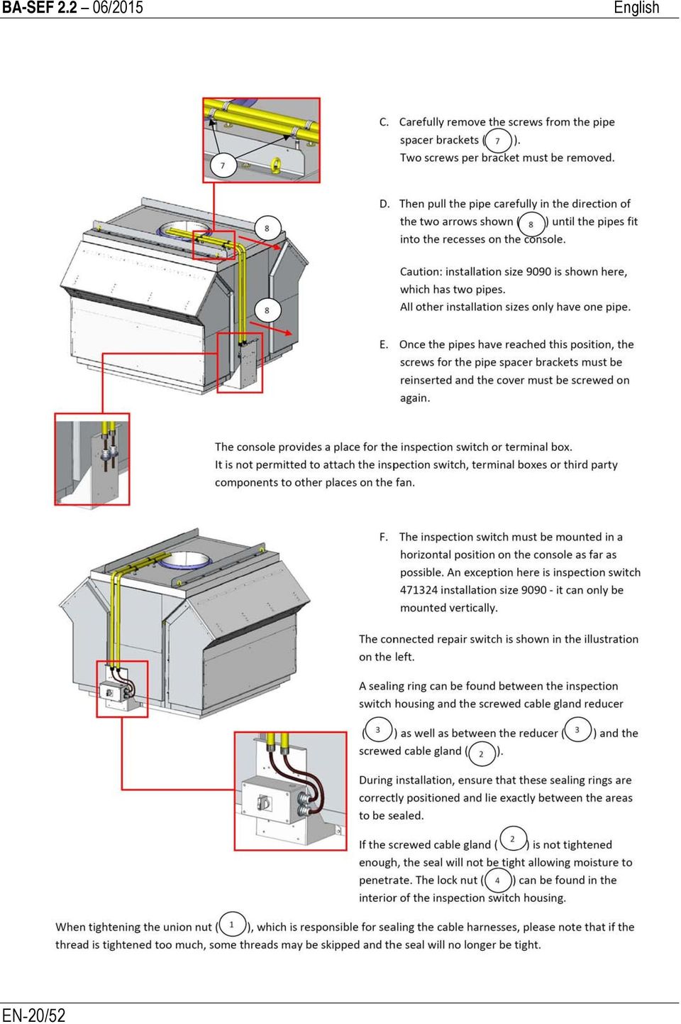
19 7.5. Installation instructions for inspection switch for RDM 56/57 EN-19/52

20 EN-20/52
21 8. Electrical Connection 8.1. Safety Instructions for Electrical Connection DANGER Caution! Danger of electric shock! Observe the safety instructions and preventive measures in Chapter 4 and the relevant legal requirements. DIN EN ; DIN VDE CAUTION In order to prevent the installation from unexpected starting a service switch is recommended. (Option). CAUTION When connecting the smoke extracting fans, special attention should be paid to cable routing! Protect cables in hot interior space. Protect cable from hot exhaust air Prefer cable routing through the outside Protect cables against hot fan housing surfaces, e.g. through metal tube with distance pieces. Do not mount isolators directly at the fan housing. CAUTION In the case of fire, the smoke extract fans require a secured electric supply. Securing of electric supply exceeding public mains supply by means of electric power generation units (equivalent current) depends on the respective public law requirements. For electric supply of smoke extract fans in buildings only use electric line systems whose function maintenance class was proved by a general test certificate issued by the building authorities. The electric line systems must be laid with protection against mechanical damage. They must not touch the fan housing at any point. The electric line systems must be laid up to the fan/motor terminal box - in case of installation in buildings - outside of the room to be extracted as well as outdoors. Please check the national regulations, especially if established, the latest Directive on fire protection requirements for electric feed systems. EN-21/52
22 8.2. Connecting the Motor Note All smoke extract fans are supplied with the main cable ready for connection. The cable is either lead lose to outside or the connection box is placed for easy access. The wiring diagram is placed inside the connection box or sticked to the fan casing. Current, voltage and frequency of mains supply checked for conformity with fan type plate and motor rating plate. Star-delta or soft start provided for motors with a nominal output >4 kw. Service switch present if applicable. Smoke extract fans require in case of fire a saved electrical power supply. For this reason the fans must operated without frequenzy converter during smoke extract. The fan has been protected against an unexpected start! Chapter 4. Safety to be respected! 1. If necessary install service switch. 2. Mains to be lead from outside to the connecting cable or to the service switch. 3. Fan to be connected acc. to attached wiring diagram. 4. Ensure that all electrical safety devices are in place and connected. CAUTION The motors are designed for S1 continual operation. With more than three starts per hour the suitability of the motor is to be confirmed by Nicotra Gebhardt GmbH. EN-22/52
23 8.2.1 Connection-Example RDM 56 / 57 Fig 8-1: Example RDM 56 /57 = Isolator (Accessory) = Optical smoke detector (Accessory) = Manual release button (Accessory) = Smoke detecting switching (Accessory) = Prefer cable routing from the outside = Protect cables in hot interior space = Cable duct with motor feed cable Connection-Example RWM 57 Fig 8-2: Example RWM 57 = Isolator (Accessory) = Optical smoke detector (Accessory) = Manual release button (Accessory) = Smoke detecting switching (Accessory) = Prefer cable routing from the outside = Protect cables in hot interior space EN-23/52
24 8.2.3 Connection-Example REM / RER Fig 8-3: Example REM / RER Fig 8-4: Example SLCS Connection-Example SLCS = Isolator (Accessory) = Optical smoke detector (Accessory) = Manual release button (Accessory) = Smoke detecting switching (Accessory) = Prefer cable routing from the outside = Protect cables in hot interior space = Wire duct, on site = Isolator (Accessory) = Optical smoke detector (Accessory) = Manual release button (Accessory) = Smoke detecting switching unit (Acc.) = Prefer cable routing from the outside = Protect cables in hot interior space EN-24/52
25 8.2.5 Connection-Example AGM / RGM Fig 8-5: Example AGM / RGM = Optical smoke detector (Accessory = CO-sensor (Accessory) = Smoke detecting switching unit (Acc.) = Prefer cable routing from the outside = Protect cables in hot interior space 8.3. Motor Protection CAUTION No standard motor protection has been provided by the supplier! In the case of smoke extract fans, the motor must not be protected in the event of fire. All motor protection devices must be automatically bypassed and/or deactivated. For this by-pass action use the smoke detector-switch board (option) 8.4. Carrying out a Test Run Risk of injury from rotating impeller! Never reach into the impeller when the fan is open. DANGER 1. Disconnect motor from the mains. 2. Take measures to prevent roof fan from being switched on accidentally. 3. Clear the ducting system and fan of all foreign bodies (tools, small parts, construction waste, etc.). 4. Close all the inspection openings. 5. Switch on fan and check direction of rotation of impeller by comparing it with the arrow on the fan indicating the direction of rotation. 6. If the direction of rotation is wrong, reverse the polarity of the motor having due regard to the safety instructions. 7. Once operating speed has been reached measure the current consumption and compare it with the nominal motor current on the roof fan type plate or motor rating plate. 8. If there is continuous overload switch the roof fan off immediately. 9. Check that the roof fan runs smoothly and quietly. Ensure that there are no unusual oscillations or vibrations. 10. Check the motor for any abnormal noises. EN-25/52
26 9. Commissioning / Operation 9.1. Commissioning the Roof Fan DANGER CAUTION Risk of injury from rotating parts and hot surfaces! Ensure that all the safety devices are fitted. Ensure that the impeller has been secured acc. to DIN EN ISO Material damage may be caused by overload from excessive starting currents! Adhere to the output limits imposed by the power supply company. Note After having achieved the complete installation of smoke extract fans a trouble free interaction of all components has to be stated by a commissioning acceptance check. The smoke extract fan manufacturer may point out the necessity of this acceptance check. It has to be initiated by the owner of the installation. The results of the acceptance check have to be documented by the owner and to be filed by the owner / user. 1. Check working order of all control instruments connected. 2. Switch on smoke extract fan. EN-26/52
27 10. Maintenance Safety Instructions for Maintenance Observe the safety instructions and preventive measures in Chapter 4 and the relevant legal requirements. Follow the directions of the motor supplier and the instructions specified by the manufacturers of the switches and control units. Works on the impeller may only be executed after a safe cut off of the electrical feed! WARNING Note The smoke extract fans must be checked at regular intervals according to the instructions attached. The user has to document his checks. The documents are to be kept by the user of the smoke extract installation. CAUTION Possible necessary repair or major maintenance works have to be made in the works of the manufacturer or by staff persons from Nicotra Gebhardt GmbH or by persons of companies witch are authorised by Nicotra Gebhardt GmbH. CAUTION No high pressure cleaners (steam jet cleaners) are to be used! CAUTION If the state of the fan does not allow adapted action for repair it has to be put out of order immediately and to be replaced if required! Maintenance Preparation 1. Disconnect motor from the mains. 2. Fans fitted with an inspection switch should be switched off by means of the inspection switch. 3. Take measures to prevent roof fan from being switched on accidentally. 4. Wait until the impeller has stopped. 5. Wait until all hot surfaces have cooled down. 6. Remove any residues from the fan. EN-27/52
28 Tilting the Smoke Extract Roof Fan Up / Back (Except Size 9090) Risk of injury from roof fan falling back suddenly from tilted position! Take measures to prevent smoke extract roof fan from swinging back. DANGER Fig 10-1: Tilting Tilting up Maintenance prepared see item 10.2! Side panels removed 1. Remove screws (8). 2. Tilt back central section (10) 3. Secure central section on both sides using screws (8) and nuts in articulated joint (9). Tilting back (after servicing) Maintenance prepared see item 10.2! 1. Prop up tilted roof fan (release locking screws). 2. Remove locking screws from articulated joint (9) and lower roof fan carefully down out of tilted position. 3. Insert and tighten fixing bolts (8) Smoke Extract Wall Fan RWM 57 Fig 10-2: RWM-Service Maintenance prepared see item 10.2! Remove inspection door cover (1) and inlet guard (2) The impeller now can be inspected and/or cleaned. Inlet side connection EN-28/52
29 Smoke Extract Centrifugal Fans REM BU / REM BI Maintenance prepared see item 10.2! According to fitting situation installation elements have to be unfitted for inspection and maintenance Smoke Extract Centrifugal Fans RER 13- / C Maintenance prepared see item 10.2! According to fitting situation installation elements have to be unfitted for inspection and maintenance. Belt drive / Bearings The belt drive is from the run-in phase onwards generally maintenance free. It is however recommended that depending on the installation site and the type of operation the belt tension is regularly checked. The test force Fp is given on the type plate and the design sheet. Fig 10-3:V- Belt drive Fig 10-4: Flat belt drive Tensioning rules for V-belt drives L = Span between shaft centres b = Belt deflection under test force Fp Fp = Test force in N from the Gebhardt documentation The correct tensioning for a belt is achieved if the individual test force Fp produces a belt deflection b of 16 mm per 1000 mm of span. Tensioning instructions for flat belts LMu = Measurement mark spacing on intentioned flat belt LMg = Measurement mark spacing on correctly tensioned belt * = Increase in mm from Gebhardt documentation The correct belt tensioning has been achieved when the measurement mark spacing LMu has increased by *. The adjustment should take place in two stages with a time period of some hours in between to avoid overloading the bearings. Tensioning instructions for V-belts and flat belts Changing Belts Reduce centre distance until the new belt/s can be easily fitted by hand. The tensioning of the belt follows in accordance with the tensioning rules. Observe the running-in phase! EN-29/52
30 Pulley changing To release the pulley: To fix the pulley: Fig 10-5:release Fig 10-6: fixing 1. Unscrew the bolts (3). 2. Tighten the socket head cap screw in the threaded hole (4). 3. Press the clamping bush out of the tapered hole. 4. The pulley can now be easily slid of the shaft Pull the pulley and the clamping bush together by means of the socket head cap screw (3) Note The belt drive of the smoke extract fan must not be modified after installation! Otherwise the certificate will become unvalid! CAUTION Motor pulley and fan pulley have to be perfectly in line. Observe instruction for fitting and tensioning belts. Torque values supplied by the manufacturer have to be strictly respected. CAUTION The fan bearings are Lifelong lubricated as standard (20,000 or 40,000 hours of operation). However in heavy duty operational conditions maintenance intervals are to be established by the operator. Our maintenance guidelines on later lubrication are to be observed. Grease usage period and relubrication intervals see appendix Smoke Extract Axial Fans SLCS Maintenance prepared see item 10.2! According to installation situation unfit and remove parts for inspection and maintenance Smoke Extract Jetfan AGM 01 / 11 In the case that an inspection or maintenance works through intake or discharge openings are not possible or if the motor impeller has to be unfitted proceed as follows: Maintenance prepared see item 10.2! 1. Disconnect motor feed cable at connection box (1). EN-30/52
31 Fig 10-7: AGM- Fan dismantling 2. Unfasten screws of connection-box support plate(2). 3. Insert support plate (2) diagonally together with connection box into the fan casing. Prior to unfasten the bolts of the motor-fan-unit (3) ensure, by using suitable device (hoist, lifting table etc.), that the unit may not fall down! DANGER! 4. Unscrew bolts (3) of fan support plate. 5. Lower motor-fan-unit (4) from the casing. The assembly will be executed inversely to the dismantling order. The new start-up has to be proceeded as per chapter 8.3 and Smoke Extract Jetfan AGM 02 / 12 In the case that an inspection or maintenance works through intake or discharge openings are not possible or if the motor impeller has to be unfitted proceed as follows: Maintenance prepared see item 10.2! DANGER! Fig 10-8: AGM- Damper dismantling Prior to unfasten the bolts of the silencer (1) ensure, by using suitable device (hoist, lifting table, under structure etc.), that the unit may not fall down! 1. Unscrew fixing bolts (1) of silencer. EN-31/52
32 2. Lower silencer (2) and (3) carefully! 3. If necessary unfasten ceiling bolts when fan is secured against falling down. 4. Lower fan carefully. Fig 10-9: RGM- Impeller dismantling The assembly will be executed inversely to the dismantling order. The new start-up has to be proceeded as per chapter 8.3 and Smoke Extract Jetfan RGM 91 The inspection of the fan is to do through inlet and outlet side. If the motor-impeller has to be unfitted for cleaning the following procedures are recommended: Maintenance prepared see item 10.2! 1. Motor connection cables to be unfastened at connection box (1). 2. Seize connection cable through open inspection door (2) and tear it from connection box (1) to inside. WARNING Before loosening bolts of the motor impeller (3) care must be taken to prevent the unit from falling down e.g. by using a lifting device or elevating platform! 3. Loosen bolts (3) 4. Get motor impeller unit (4) out of the casing by lowering it. The assembly is made in a reverse operation sequence. For putting into operation again follow instructions of chapter 8.3 und Observing Regular Inspection Intervals EN-32/52 In order to assure a safe operation we recommend to make checks of the fans in regular intervals by specialised service personnel or by a specialised company and to document the result of these checks. The type, magnitude, and interval period as well as all works which may be necessary in addition depend on the use and the surrounding conditions of the
33 fan and have to be determined case by case. The recommendations for checks and maintenance acc. to VDMA Pos Description monthly ½ annual annual 1.0 Tripping device x 2.0 Fan 2.1 Check fan for function and readiness for service (trial run min. 15 min.) x Check fan for function and readiness for service (trial run min. 1 h.) x 2.2 Functional testing of the automatic bridging of all excess temperature and over current monitors x 2.3 Relubricate bearing see lubrication chart 2.4 Check V-belt for damage, tension and alignment x 2.5 Check for soiling, damage, corrosion and fastening x 2.6 Cleaning in order to maintain functioning x 2.7 Check impeller direction of rotation x 2.8 Check connections for leaks x 2.9 Check impeller for unbalanced state x 2.10 Check safety devices for functioning x 3.0 Motor 1 ) 3.1 Check externally for soiling, damage, corrosion and fastening x 3.2 Cleaning in order to maintain functioning x 3.3 Check bearings for noises 1 ) x 3.4 Check terminal clamps for tight fit x 3.5 Measure voltage x Table 10-1: Maintenance CAUTION CAUTION CAUTION 1 ) The motor bearings are supplied permanently lubricated by the factory; experience has shown that the grease need be changed after several years only under normal operating conditions. It is recommended, however, to exchange the motor bearings after approx. two years. In case of bearing noises contact the Nicotra Gebhardt GmbH service department in order to examine or change defective bearings. The maintenance instructions of the motor supplier as well as the instructions for the switches and control units have to respected. Fan Ranges RDM, RWM, REM, RER The fan has to be checked regularly whether vibrations may occur. The maximum vibration speed in radial direction must not exceed 4.5 mm/s to monitored at the bearing or bearing housing of the fan or motor. For fans of a impeller diameter up to 315 mm a vibration speed of up to 7,1 mm/s is acceptable. Minimum maintenance intervals see Table 10-1 Recommendations for maintenance Bearing Monitoring by SPM Shock Impulse Transducer EN-33/52
34 The bearing monitoring by a SPM shock impulse transducer has been approved under the aspect of fire resistance (filed as BB-TUM ) at Technical University Munich. The system enables to get information about the state of the roller bearing and its lubricating film. The evaluation of the transmitted data is made by comparing them with the basic data supplied for every ISO-bearing number. The transducer sensors are mounted to the motor and they are capturing the impulses from the turning bearing. The evaluation of the signal in made following to the principle of a traffic light This means: - green Perfect condition of bearing and lubricating film - yellow Bearing change to be done soon - red Bearing change to be done Manual Data Read out The state of the bearing is read out by a manual read out unit. The data measurement is realised with a connection box fixed to the fan for easy access. The software supplied with the measuring unit includes a transmission function for easy storing and visualisation Data read out by automatic query at a distance The shock impulse transducers fixed to the motor are connected to an intermediate module. From this module a 4-wire cable (not part of our supply) ensures the connection to the switch board of a BMS. The query or monitoring function is then ensured by the central control system Bearing status monitoring system - SPM Through use of the bearing status monitoring system (SPM) the required maintenance tasks and inspections can be significantly facilitated. The shock-pulse method (SPM) checks the mechanical status of roller bearings, detects installation errors, as well as poor or inadequate lubrication. Consequently with the high-quality SPM bearing monitoring system the interval between bearing replacements prescribed by the manufacturer can be significantly extended. This means that bearings do not need to be replaced every 4 years as recommended by the motor manufacturers, but rather this task can be performed based on the status - as shown on the display by the SPM bearing status monitoring system. EN-34/52 The display "Green" shows the new bearing status - bearing replacement is not necessary. The display "Yellow" indicates changes in the bearing. These changes can be induced through decreasing lubricating characteristics or through mechanical changes. - Bearings do not need to be replaced - However the bearing must be observed at shorter intervals
35 The display "Red" indicates a severe lack of lubrication and/or bearing damage. The SPM spectrum shows clearly whether the problem is due to a lack of lubrication or bearing damage. - Bearing replacement is necessary The actual time of bearing replacement is decided by the owner or the owner's commissioned service partner. A measurement during a trial run is not necessarily required to commission the system. It suffices to enter the ISO number of the bearing and the nominal motor speed (found on the motor type plate) in the SPM system when the bearing is checked for the first time. For fans with belt drive, when using pedestal bearings, the rpm information on the fan rating plate must be used. 11. Disturbances If disturbances occur during operation which cannot be repaired by maintenance personnel please contact the service department of Nicotra Gebhardt GmbH. CAUTION Roof fan may be damaged by improper operating conditions! Switch the smoke extract fan off immediately if permissible limits are exceeded and in the event of irregularities or disturbances. 12. Service, Spare Parts and Accessories Nicotra Gebhardt GmbH Gebhardtstrasse Waldenburg Germany Phone: +49 (0) Fax: +49 (0) info@gebhardt.de Ordering Spare Parts Use only genuine spare parts supplied by Nicotra Gebhardt GmbH as featured in the list of spare parts. The use of spare parts supplied by other manufacturers may compromise the safety of the equipment. The requirements for CE conformity are no longer met if spare parts supplied by other manufacturers are fitted. Nicotra Gebhardt GmbH shall not accept any liability or provide any warranty cover in respect of primary or secondary damage arising as a consequence of using spare parts supplied by other manufacturers. Spare parts can be online ordered by Nicotra Gebhardt Part-Shop on our website. EN-35/52
36 12.2. Accessories Nicotra Gebhardt GmbH has a wide range of accessories for economic and efficient use of the fans. Accessories are optional and always need to be ordered separately. Spare parts should be selected on the basis of the technical specifications or via our electronic selection program. Accessories are supplied with separate operating or installation instructions unless their installation or use is self-explanatory. EN-36/52
37 13. Annex Further Documentation Supplied by Nicotra Gebhardt Table 13.1: Further documentation Type of Documentation Electric wiring diagram EC Declaration of Conformity to EC Machinery Directive (2006/42/EC) EC Declaration of Conformity to EC Low Voltage Directive (2006/95/EC) EC Declaration of Conformity to EC- Directive for the setting of ecodesign requirements for energy-related products (2009/125/EC) EC-Declaration of incorporation Declaration of performance (DoP) to Regulation (EU) 305/2011 DiBt-Cerificate File Location on product / Internet Connection diagrams: Annex Annex Annex Annex Annex on product / Internet 13.2 Appendix to RER - Bearings Maintenance Note For service and maintenance observe the following instructions 4. Safety Chapter Service/ Maintenance Chapter Safety Notes Chapter 10.1 CAUTION It is necessary to use precision bearings submitted to a noise check and designed for a nominal lifetime (L10h as per DIN ISO 281-1) of 20,000 and 40,000 hours of operation respectively. In order to prevent the permitted bearing loadings from overloads, the limiting values for the belt tension forces must be respected (technical catalogue) Bearings without relubrication device The bearings are normally supplied greased for life with a high-performance grease that is resistant to ageing and does not require maintenance under normal operating conditions. If it is necessary to replace the bearings as a result of normal wear and tear, please get in touch with our service department or with a company authorised by Nicotra Gebhardt GmbH Bearings With IWN 01- Lubrication Device CAUTION The bearings must be greased at regular intervals in order to attain the maximum permissible life of the bearings under more severe operating conditions. The intervals depend on the relevant operating conditions and should be EN-37/52
38 set by the operator. The values given in the lubrication interval tables should be taken as guidelines. RER /.1000; RER /.1000; RER / Lubrication Intervals If no greasing intervals are specified, they lie nominally above 8000 operating hours. Hence, regreasing must take place at least once a year! The lubrication intervals given in the tables apply for bearings on a horizontal shaft where the temperature of the bearing outer ring does not exceed +70 C. In the case of temperatures above +70 C, the lubrication interval must be reduced by half for each 15 C by which this temperature is exceeded In the case of temperatures below +70 C, the lubrication interval can be lengthened correspondingly (the lubrication interval should never be more than doubled). If these values produce lubrication intervals that are more than a year, it is nonetheless necessary to lubricate once a year Lubrication In the case of lubrication during operation, the prescribed amount of the corresponding type of grease is pressed into the bearing by the hydraulic-type lubricating nipple placed on the outside. The old grease that is pressed out can be removed during a brief stop. The bearings should be cleaned and completely regreased after they have been lubricated three times. Grease quantity at sizes RER 13-/ Grease quantity 30 g 40 g 60 g 90 g 120 g Lubrication intervals in hours of operation for fan speed n in rpm RER 13- Grease 300 1/min 400 1/min 500 1/min 600 1/min 700 1/min 800 1/min 900 1/min /min g h 6500 h 5500 h 5000 h 4500 h 4000 h 3500 h g 9500 h 7500 h 6000 h 5000 h 4500 h 4000 h 3500 h 3000 h g 9000 h 7000 h 5500 h 4800 h 4300 h 3500 h 3000 h g 9000 h 7000 h 5500 h 4800 h 4300 h 3500 h - - EN-38/52
Installation and safety instructions for AC/DC built-in devices
 The device type and date of manufacture (week/year) can be found on the device rating plate. In the event of any queries about the device, please quote all the details given on the rating plate. For further
Operating Instructions Drill rig DRU160
 Operating Instructions Drill rig DRU160 Index 000 / 001 Original operating instructions 10988825 en / 20.10.2009 Congratulations! With a Hydrostress unit from TYROLIT you have chosen a tried and tested
Operataing Manual. Single stage radial Fan. Model MKV/TKV
 01.2011 Operataing Manual Single stage radial Fan Model MKV/TKV REITZ-SCHWEIZ VENTILATOR AG Zentweg 11 CH-3006 Bern Telefon +41 (0) 31 / 938 85-85 Telefax +41 (0) 31 / 938 85-86 Internet: www.reitz-schweiz.ch
TIG INVERTER INSTRUCTION MANUAL
 TIG INVERTER INSTRUCTION MANUAL Contents Warning General Description Block Diagram Main Parameters Circuit Diagram Installation and Operation Caution Maintenance Spare Parts List Troubleshooting 3 4 4
AKRAPOVIC SLIP-ON EXHAUST SYSTEM for the HONDA CB1000R
 Installation instructions: *502131* AKRAPOVIC SLIP-ON EXHAUST SYSTEM for the HONDA CB1000R Congratulations on purchasing an Akrapovic exhaust system. Please read these installation instructions carefully.
SunMaxx Solar Filling Station Operating Instructions
 SunMaxx Solar Filling Operating Instructions Content 1. Declaration of conformity... 2 2. Introduction... 2 3. Transportation and unpacking... 4 4. Mounting and commissioning... 5 5. End of operation...
LUCCI AIRFUSION QUEST II CEILING FAN
 LUCCI AIRFUSION QUEST II CEILING FAN WITH IR REMOTE INSTALLATION OPERATION MAINTENANCE WARRANTY INFORMATION CAUTION READ INSTRUCTIONS CAREFULLY FOR SAFE INSTALLATION AND FAN OPERATION. V1.0 QUEST II IR
BC & BCH SERIES INDOOR / OUTDOOR INSTALLATION
 Air Conditioning Central Heating & Cooling BC & BCH SERIES INDOOR / OUTDOOR INSTALLATION INSTALLATION AND SERVICE MANUAL 2 PROJECT: ADDRESS: MODEL: SERIAL NUMBER: INSTALLER: ADDRESS: PHONE NUMBER: INSTALLATION
Drive shaft, servicing
 Volkswagen Passat B6 - Drive shaft, servicing Стр. 1 из 41 40-7 Drive shaft, servicing Drive shafts, overview I - Assembly overview: Drive axle with CV joint VL100 40-7, Drive axle with CV joint VL100,
IMPORTANT SAFETY NOTICE
 IMPORTANT SAFETY NOTICE To: Our Valued Customers User safety is a major focus in the design of our products. Following the precautions outlined in this manual will minimize your risk of injury. ITT Goulds
Operation Instructions. KleeBlower Compressor/Vacuum pumps. Models: KB129 KB8415
 Operation Instructions KleeBlower Compressor/Vacuum pumps Models: KB129 KB8415 Brd. Klee A/S All rights reserved Edition 01/2012 Head office: Branch office: Brd. Klee A/S Klee Engineering Ltd Gadagervej
Cooling system components, removing and installing
 Page 1 of 34 19-1 Cooling system components, removing and installing WARNING! The cooling system is pressurized when the engine is warm. When opening the expansion tank, wear gloves and other appropriate
ATS Overhead Table Shelf System INSTRUCTION MANUAL
 ATS Overhead Table Shelf System INSTRUCTION MANUAL ATS Overhead Table Shelf System Instruction Manual Warranty Newport Corporation warrants this product to be free of defects in material and workmanship
15GAL STEEL OIL DRAIN WITH 110V PUMP
 15GAL STEEL OIL DRAIN WITH 110V PUMP OWNER S MANUAL WARNING: Read carefully and understand all ASSEMBLY AND OPERATION INSTRUCTIONS before operating. Failure to follow the safety rules and other basic safety
This instruction is valid for all ACD pump models shown on page 2
 Screw pumps ACD Maintenance and Service Instruction This instruction is valid for all ACD pump models shown on page 2 Contents Page List of components 2 Exploded view/ordering code 3 Service intervals
Portable Air Conditioner
 Portable Air Conditioner Owner's Manual Model:3 in 1 12,000 Btu/h Series 3 Please read this owner s manual carefully before operation and retain it for future reference. CONTENTS 1. SUMMARY...1 2. PORTABLE
Industrial Process Pump Safety Manual IMPORTANT SAFETY NOTICE
 Industrial Process Pump Safety Manual IMPORTANT SAFETY NOTICE To: Our Valued Customers User safety is a major focus in the design of our products. Following the precautions outlined in this manual will
Operating instructions. SCORP 220 Plus SCORP 360. Pipe Cutter. Code 790 014 762 Machine-no.:
 precision. power. simplicity. Operating instructions Pipe Cutter SCORP 220 Plus SCORP 360 Code 790 014 762 Machine-no.: All rights reserved, in particular the rights of duplication and distribution as
Mounting Instructions. Torque Transducer. A0329 3.2 en
 Mounting Instructions Torque Transducer T5 T5 Contents 3 Page Safety instructions.............................................. 4 1 Measuring characteristics..................................... 7 2 Mounting.....................................................
Operating instructions
 ebm-papst Mulfingen GmbH & Co. KG Bachmühle D-74673 Mulfingen Phone +49 (0) 7938 81-0 Fax +49 (0) 7938 81-110 info1@de.ebmpapst.com www.ebmpapst.com CONTENTS 1. SAFETY REGULATIONS AND S 1.1 Levels of hazard
Owners & Installation Manual for the Sheridan, Mountainair, Pine Valley and Old Forge Ceiling Fan Family
 Owners & Installation Manual for the Sheridan, Mountainair, Pine Valley and Old Forge Ceiling Fan Family Part of the Kiva Lighting Family Custom Lighting and Fans Since 1992 1312 12th St NW Albuquerque,
INSTALLATION, OPERATION & MAINTENANCE INSTRUCTIONS ELECTRIC HEATING UNITS MODEL: ETA / EKI
 INSTALLATION, OPERATION & MAINTENANCE INSTRUCTIONS ELECTRIC HEATING UNITS MODEL: ETA / EKI Page 2 / 16 CONTENTS 1 GENERAL... 3 2 SAFETY... 3 2.1 Safety instructions... 3 2.2 Correct use... 3 3 DESCRIPTION
PBX Series Quick Fit Connector Bimetallic Steam Traps
 6262100/6 IM-P626-01 ST Issue 6 PBX Series Quick Fit Connector Bimetallic Steam Traps Installation and Maintenance Instructions 1. Safety information 2. General product information 3. Installation 4. Commissioning
Installation guide for the SafeLine type anchorage device. Tested in compliance with EN 795: 1996. No.: SE-...
 Installation guide for the SafeLine type anchorage device Tested in compliance with EN 795: 1996 No.: SE-... Version: 09.10.2008 SE 67 Subject to technical alterations! Contents 1. General information
INSTALLATION AND MAINTENANCE INSTRUCTIONS FOR THREE PHASE INDUCTION MOTORS
 INSTALLATION AND MAINTENANCE INSTRUCTIONS FOR THREE PHASE INDUCTION MOTORS Frames 143T - 449TZ 5100 North IH 35 Round Rock, Texas 78681 Phone: 800-451-8798 512-255-4141 Fax: 512-244-5512 RECEIVING 1. Check
WE-350 Series ¼ Turn Electric Actuator
 WE-350 Series ¼ Turn Electric Actuator Operation and Installation Manual Pg 1 (Rev. 020113) Table of Contents 1.0 General 1.1 Pre-Installation Inspection 1.2 Storage 1.3 Features & General Information
Roller Chain Coupling
 Roller Chain Coupling Features 1. Simple structure A roller chain coupling consists of one duplex roller chain and two sprockets for a simplex chain. Handling is very simple as both the shafts (driving
Operating Instructions
 Operating Instructions Cable Glands Ex d and Ex e with Compound > Contents 1 Contents 1 Contents...2 2 General Information...2 3 General Safety Information...3 4 Designated Use...4 5 Technical Data...4
Operating instructions
 ebm-papst Mulfingen GmbH & Co. KG Bachmühle D-74673 Mulfingen Phone +49 (0) 7938 8-0 Fax +49 (0) 7938 8-0 info@de.ebmpapst.com www.ebmpapst.com CONTENTS. SAFETY REGULATIONS AND NOTES. Levels of hazard
Maintenance and Service Instruction
 Screw pumps E4 Maintenance and Service Instruction E4 1 IMO AB This instruction is valid for all E4 pump models shown on page 2 Contents Page List of components 2 Exploded view/ordering code 3 Service
Load Limiter ULS-60 ULS-80 ULS-100 ULS-125. Table of Contents. Assembly Instructions Load Limiter ULS-60, -80, -100, -125
 Load Limiter ULS-60 ULS-80 ULS-100 ULS-125 Version 2.0 Last revision November 2012 Dear customer, Thank you for the confidence that you have placed in our company by purchasing an IPR load limiter. Every
Andersen Electric Window Opener for Andersen Awning and Roof Windows
 W A Electric Window Opener Electric Window Opener for Awning and Roof Windows Congratulations! You have just purchased one of the many fine products. For ease of installation and continued enjoyment of
USER S MANUAL HSC-24A
 AIRREX AIR CONDITIONER USER S MANUAL HSC-24A Thank you for purchasing an AIRREX AIR CONDITIONER. BEFORE operation please read this user s manual carefully. Keep this manual readily available. It is ESSENTIAL
ARCO Electric Products Installation and Maintenance Manual Low Voltage Automatic Power Factor Correction Capacitor Systems 2013
 ARCO Electric Products Installation and Maintenance Manual Low Voltage Automatic Power Factor Correction Capacitor Systems 2013 READ CAREFULLY These instructions are intended to cover good practices in
Subminiature Load Cell Model 8417
 w Technical Product Information Subminiature Load Cell 1. Introduction... 2 2. Preparing for use... 2 2.1 Unpacking... 2 2.2 Using the instrument for the first time... 2 2.3 Grounding and potential connection...
Accessory Manual Ventilation Section Model Comfort Circle
 Accessory Manual Ventilation Section Model Comfort Circle Manual version:. R a Copyright and trademarks All the information and drawings in this manual are the property of Biddle and may not be used (other
Front axle components, overview
 just a test. Front axle components, overview 40-1 General Information Load bearing components and parts of the suspension must not be welded or straightened. Vehicles without drive axle must not be moved,
Jet Propulsion System
 This repair manual is valid for the following jet pump variants: 0333_ 0 V3 007 3. 033_ 0 V 007 3. 0380_ 3 V 007 3. 0335_ 3 V 007 3. 033_ 66 V 008. 0338_ 66 V 008. Table of Contents Before you begin working
IMPORTANT INSTRUCTIONS & OPERATING MANUAL. Houston 50 Inch Electric Wall Mounted Fireplace Black / White
 IMPORTANT INSTRUCTIONS & OPERATING MANUAL Houston 50 Inch Electric Wall Mounted Fireplace Black / White Model Number:MFE5050BK Model Number:MFE5050WH Read these instructions carefully before attempting
X8 X13A X14 - AC Gearless
 This manual is to be given to the end user X8 X13A X14 - AC Gearless Installation and maintenance THIS MANUAL MUST REMAINS WITH THE MACHINE. THE TABLE (page 4) MUST BE SUPPLEMENTED TO ATTEST GOOD REALIZATION
Ergo-Pro Single Line Solar Station Installation and Operating Instructions
 Rp 3/4 Ergo-Pro Single Line Solar Station Installation and Operating Instructions Item No Pump type 677.21.70 WILO ST 15/6 13 2 4 11 Technical Specifications Max. operating pressure: 6 bar Max. operating
Infrarot-Bewegungsmelder IP44
 Infrarot-Bewegungsmelder IP44 infrared motion sensors IP44 ODA (weiß) slim ODA (schwarz) slim 95174 96000 ODA (weiß) ODA (schwarz) 95175 96001 Betriebsanleitung User s Manual User s Manual infrared motion
Cable Drum Machine. Operation Manual BC260 SERIES. Cleans 1 1/4" to 3" lines up to 50'
 Cable Drum Machine Operation Manual BC260 SERIES Cleans 1 1/4" to 3" lines up to 50' Used For: Sink, Shower & Floor Drains 42FM " WARNING - Read All Instructions, When Using Electric Tools, Basic Safety
POSEIDON 2-29, 2-25 & 2-22 POSEIDON 2-29, 2-25 & 2-22 XT
 POSEION 2-29, 2-25 & 2-22 POSEION 2-29, 2-25 & 2-22 XT Repair Manual Index A. Safety precautions 3 B. Technical data 4 C. Structure 5-6. Service / Repair 7-23 E. Tools 24 F. Function 25-26 G. Electric
KESSEL KTP 500 Submersible Pump with lateral and vertical outlet connection Order Numbers 28710, 28810, 28850
 INSTALLATION AND OPERATING INSTRUCTIONS KESSEL KTP 500 Submersible Pump with lateral and vertical outlet connection Order Numbers 28710, 28810, 28850 Product advantages Automatic float switch as water
Cooling system components, removing and installing
 Engine BHW Cooling system components, removing and installing Page 1 / 24 19-1 Cooling system components, removing and installing Warning! When doing any repair work, especially in the engine compartment,
LU6X-130 Instructions and Parts List (including LU6X Basic) Operating Instructions
 Operating Instructions") LORTONE LU6X-130 Item # 061-092 LU6X Basic Item # 061-090 LU6X-130 Instructions and Parts List (including LU6X Basic) Operating Instructions Introduction The LU6X is one the most versatile pieces of equipment
LORTONE LU6X-130 Item # 061-092 LU6X Basic Item # 061-090 LU6X-130 Instructions and Parts List (including LU6X Basic) Operating Instructions Introduction The LU6X is one the most versatile pieces of equipment
Volkswagen Jetta, Golf, GTI 1999, 2000 2.8 Liter VR6 2V Engine Mechanical, Engine Code(s): AFP 17 Engine-Lubrication (Page GR-17)
: AFP 17 Engine-Lubrication (Page GR-17)") 17 Engine-Lubrication (Page GR-17) Lubrication system components, removing and installing Oil filter housing, disassembling and assembling Oil pan, removing and installing Oil pressure and oil pressure
17 Engine-Lubrication (Page GR-17) Lubrication system components, removing and installing Oil filter housing, disassembling and assembling Oil pan, removing and installing Oil pressure and oil pressure
RPV - RP - RA air handling units
 APPLICATIONS Heating, ventilation, cooling >> FACTORIES >> WAREHOUSES >> HALLS >> DISTRIBUTION CENTRES >> COMMERCIAL PREMISES >> PLACES OF WORSHIP RPV - RP - RA air handling units www.reznor.eu RPV - RP
IMPORTANT SAFETY RULES TO FOLLOW
 WARNING FLOOR & CARPET CLEANER Any piece of equipment can be dangerous if not operated properly. YOU are responsible for the safe operation of this equipment. The operator must carefully read and follow
INFRARED QUARTZ WALL HEATER
 INFRARED QUARTZ WALL HEATER MODEL NO: IQ2000 PART NO: 6939004 MOUNTING & OPERATION INSTRUCTIONS GC0715 INTRODUCTION Thank you for purchasing this CLARKE Infrared Wall Heater. Before attempting to use this
English AUTOMATION SYSTEMS FOR SLIDING GATES. Operating and installation instructions SLIDE SERIES
 English AUTOMATION SYSTEMS FOR SLIDING GATES Operating and installation instructions SLIDE SERIES v.0 Rev /202 INDEX ) General Safety Regulations... pág. 0 2) Description... pág. 02 3) Technical Specifications...
BATHROOM HEATER. User's Manual. Page 2...A515 Page 9...A716
 BATHROOM HEATER User's Manual Page 2...A515 Page 9...A716 BATHROOM HEATER User's Manual A515 SAVE THESE INSTRUCTIONS AND READ ALL INSTRUCTIONS BEFORE USING THE HEATER. Dear customers, Thank you for selecting
Operating instructions
 ebm-papst Mulfingen GmbH & Co. KG Bachmühle D-74673 Mulfingen Phone +49 (0) 7938 8-0 Fax +49 (0) 7938 8-0 info@de.ebmpapst.com www.ebmpapst.com CONTENTS. SAFETY REGULATIONS AND NOTES. Levels of hazard
Precision Miniature Load Cell. Models 8431, 8432 with Overload Protection
 w Technical Product Information Precision Miniature Load Cell with Overload Protection 1. Introduction The load cells in the model 8431 and 8432 series are primarily designed for the measurement of force
Turbocharger system components, servicing
 21-1 Turbocharger system components, servicing Engine codes: AAZ, 1Z, AHU Observe rules of cleanliness Page 21-10 Turbocharger hoses and lines, connecting Page 21-11 WARNING! Do not re-use any fasteners
MOUNTING AND OPERATING INSTRUCTIONS
 MOUNTING AND OPERATING INSTRUCTIONS CF 51/55 1. Delivery CF 51/55-1 calculator with battery (optionally with mains power supply) - 1 wall mounting bracket - package with material for sealing, screws, wall
EC DECLARATION OF CONFORMITY FOR MACHINES
 EC DECLARATION OF CONFORMITY FOR MACHINES (DIRECTIVE 98/37/EC) Manufacturer: Address: Declares that: FAAC S.p.A. Via Benini, 1-40069 Zola Predosa BOLOGNA - ITALY 770 mod. operator is built to be integrated
AC Electric Motors best practice
 If you want to learn more about best practice machinery maintenance, or world class mechanical equipment maintenance and installation practices, follow the link to our Online Store and see the Training
150W. Bench Grinder. Article number BGM6018. WEB: helpdesk@d u o n s.c o m.a u. After Sales Support TEL: 07 3188 2025 N26968
 150W Bench Grinder INSTRUCTION MANUAL MODEL NUMBER tbg-150 Article number BGM6018 AFTER SALES SUPPORT TEL: 07 3188 2025 WEB: HELPDESK@DUONS.COM.AU After Sales Support TEL: 07 3188 2025 N26968 WEB: helpdesk@d
Fixture One Power Cord One User Manual One Omega Bracket One DMX Cable - One
 1. INTRODUCTION AND UNPACKING Thank you for purchasing the MICROH LED NEO SPOT 60R moving head fixture. For your own safety and knowledge, please read this manual before installing or operating the device.
TECHNICAL DATA & SERVICE MANUAL SPLIT SYSTEM AIR CONDITIONER INDOOR UNIT: AW52AL AW64AL AW52AL 387030095 AW64AL 0.8180.463.0 07/05
 TECHNICAL DATA & SERVICE MANUAL INDOOR UNIT: AW52AL AW64AL SPLIT SYSTEM AIR CONDITIONER Model No. Product Code No. AW52AL 387030095 AW64AL 387030096 0.8180.463.0 07/05 IMPORTANT! Please read before installation
Guide for Installation and Maintenance of MacroAir (ME Series) High Volume Low Speed Fans
 High Volume Low Speed Fans") Guide for Installation and Maintenance of MacroAir (ME Series) High Volume Low Speed Fans Version 9.0 April 2014 1 Delivery: Upon receipt of fans, thoroughly inspect units for any damage sustained during
Guide for Installation and Maintenance of MacroAir (ME Series) High Volume Low Speed Fans Version 9.0 April 2014 1 Delivery: Upon receipt of fans, thoroughly inspect units for any damage sustained during
Pet hair clipper. Model 96822. Diagrams within this manual may not be drawn proportionally.
 Pet hair clipper Model 96822 Cleaning And Operation Instructions Diagrams within this manual may not be drawn proportionally. Due to continuing improvements, actual product may differ slightly from the
ROTEX SD shiftable jaw coupling
 4014 E 1 SD shiftable jaw coupling Schutzvermerk Gezeichnet: 14.08.06 Sha Ersatz für: vom 9.07.85 4014 E SD is a torsionally flexible jaw coupling shiftable at standstill. It is able to compensate for
INSTALLATION INSTRUCTIONS: Viewline 52 mm
 -5 Safety information The product was developed, manufactured and inspected according to the basic safety requirements of EC Guidelines and state-of-the-art technology. The instrument is designed for use
Addendum to the Operating Instructions
 Drive Technology \ Drive Automation \ System Integration \ Services Addendum to the Operating Instructions MOVIMOT with AS-Interface and AC Motor DT/DV Unit Replacement MOVIMOT MM..C -> MM..D with MLK3A
IMPORTANT SAFETY INSTRUCTIONS WARNING READ AND SAVE THESE OPERATING AND SAFETY INSTRUCTIONS BEFORE USING THIS HEATER.
 THERMAWAVE CERAMIC HEATER Model HZ-850 Series Model HZ-860 Series IMPORTANT SAFETY INSTRUCTIONS WARNING READ AND SAVE THESE OPERATING AND SAFETY INSTRUCTIONS BEFORE USING THIS HEATER. Warning Failure to
Hydraulic control unit series 0086-372-01
 Technical Product Information No. 1290 EN Hydraulic control unit series 0086-372-01 Contents Page About this Technical Product Information (TPI) 2 The ORTLINGHAUS numbering system 2 About the product 3
Volkswagen B3 Passat Manual Transmission 02A 34 Manual Transmission - Controls, Assembly (Page GR-34) 02A 5-speed. Gearshift cable/lever installing
 02A 5-speed. Gearshift cable/lever installing") 34 Manual Transmission - Controls, Assembly (Page GR-34) 02A 5-speed Gearshift cable/lever installing Gearshift housing repairing Gearshift lever repairing lever/relay lever, installing Gearshift mechanism
34 Manual Transmission - Controls, Assembly (Page GR-34) 02A 5-speed Gearshift cable/lever installing Gearshift housing repairing Gearshift lever repairing lever/relay lever, installing Gearshift mechanism
Volkswagen New Beetle 2.0 Liter 4-cyl General, Engine (Engine Code AEG) 17 Engine-Lubrication system (Page GR-17)
 17 Engine-Lubrication system (Page GR-17)") 17 Engine-Lubrication system (Page GR-17) Lubrication system components, removing and installing Oil pan, removing and installing Oil pressure and oil pressure switch, checking Dynamic oil pressure warning
17 Engine-Lubrication system (Page GR-17) Lubrication system components, removing and installing Oil pan, removing and installing Oil pressure and oil pressure switch, checking Dynamic oil pressure warning
COOLING SYSTEM Section Page
 5 COOLING SYSTEM Section Page 5.1 COOLANT PRE-HEATER... 5-3 5.2 COOLANT PUMP NON-EGR ENGINE... 5-7 5.3 COOLANT PUMP EGR ENGINE... 5-13 5.4 FRONT CONNECTOR HOUSING NON-EGR ENGINE... 5-17 5.5 FRONT CONNECTOR
SINGLE PHASE MOTORS. INSTALLATION AND MAINTENANCE MANUAL March 21, 2006
 SINGLE PHASE MOTORS INSTALLATION AND MAINTENANCE MANUAL March 21, 2006 Irvine, California (800) 474-0520 Indianapolis, Indiana (800) 866-7973 Hamilton, Ontario (800) 809-0330 e-mail: sales@sterlingelectric.com
Installation Instructions for Alarm Module Kit A043F059
 Instruction Sheet 07-2013 Installation Instructions for Alarm Module Kit A043F059 1 Introduction The information contained within is based on information available at the time of going to print. In line
BoWex SD, SD1 and SD2 Operating-/Assembly Instructions
 D-807 Rheine 0111 E 1 curved-tooth gear couplings are flexible shaft connections. They are able to compensate for shaft displacement caused by, as an example, inaccuracies in production, heat expansion,
Oil and Coolant Circulating Heating System. Model - OCSM
 Oil and Coolant Circulating Heating System Model - OCSM Installation & Operation Manual 216280-000 REV 2 Identifying Your System The HOTSTART heating system is designed to heat fluids for use in marine
HERZ-Thermal Actuators
 HERZ-Thermal Actuators Data Sheet 7708-7990, Issue 1011 Dimensions in mm 1 7710 00 1 7710 01 1 7711 18 1 7710 80 1 7710 81 1 7711 80 1 7711 81 1 7990 00 1 7980 00 1 7708 11 1 7708 10 1 7708 23 1 7709 01
Instruction Manual Differential Pressure Transmitter
 DE28 Instruction Manual Differential Pressure Transmitter Table of Contents 1. Safety Instructions 2. Intended Applications 3. Product Description and Functions 4. Installation 5. Commissioning 6. Maintenance
Material test chamber with mechanical convection
 FP series 400 Material test chambers Material test chamber with mechanical convection A BINDER material test chamber with mechanical convection of the FP series provides reliably short drying times and
DIAMOND Retractable Rodding Robot Model SPRAYROD-R
 2004-12-21 2 1 (23) DIAMOND Retractable Rodding Robot Model SPRAYROD-R 2004-12-21 2 2 (23) Table of contents 1 TECHNICAL DESCRIPTION...4 1.1 MAIN DETAILS...5 1.2 COMPONENTS DESCRIPTION...5 1.2.1 Pneumatic
Art.S001-S002 SOLAR MODULE WITH DELIVERY AND RETURN CONNECTIONS
 Art.S001-S002 SOLAR MODULE WITH DELIVERY AND RETURN CONNECTIONS Technical Information sheet 0001/07/Rev01 ENG FUNCTION Series S001 and S002 circulation units are applied to the primary circuit of solar
AerAtron. Ceiling fans
 AerAtron Ceiling fans User Manual & Technical Specifications Models: e502 & e503 Electricians PLEASE FOLLOW THESES INSTRUCTIONS CAREFULLY & PAY SPECIAL ATTENTION TO THE NOTES NOTES WILL ASSIST WITH AN
FOR THE FOLLOWING MODELS: EE-8075W EE-8075O EE-8075R EE-8075BK
 FIREPLACE HEATER FOR THE FOLLOWING MODELS: EE-8075W EE-8075O EE-8075R EE-8075BK If you have any questions about the operation of your fireplace heater, please contact Crane Customer Care. Toll Free: 888-599-0992
Ceiling Mount Air Handler Manual
 www.surna.com 303.993.5271 Ceiling Mount Air Handler Manual Models: CMAH12, CMAH18, CMAH24, CMAH30, CMAH36, CMAH48, CMAH60 Revised: September 2014 Table of Contents Warranty Information 4 Limited Warranty
Luna/200. Luna/275. Ceiling hoist. User instruction. Important - warning. This manual must be read before the Luna is used
 Luna/200 Luna/275 Ceiling hoist User instruction! Important - warning This manual must be read before the Luna is used This manual is intended for technicians, installers, therapists and other personnel,
3 IN 1 BATHROOM HEATER
 3 IN 1 BATHROOM HEATER MODEL NO.: A515 - SH MINI FUNCTION: HEATER, EXHAUST FAN AND LIGHT Dear customers, Thank you for selecting the AUPU 3 in 1 Bathroom Heater. Please read all instructions before commencing
Installation, operation and maintenance manual TX 35A
 Installation, operation and maintenance manual TX 35A Rev.10 may 2012 Page 1 of 18 1.0.0 Table of contents INSTALLATION, OPERATION AND MAINTENANCE MANUAL...1 1.0.0 TABLE OF CONTENTS...2 2.0.0 ILLUSTRATIONS...2
AerAtron. Ceiling fans
 AerAtron Ceiling fans User Manual & Technical Specifications Models: e502 & e503 Australian edition 2011 Instructions...3 General precautions...3 Location and installation requirements for your fan...3
SMD Rework Station TABLE OF CONTENTS
 SMD Rework Station Thank you for purchasing the Hakko 50B SMD Rework Station. The Hakko 50B is designed to solder and desolder surface mounted devices with hot air. Please read this manual before operating
IH 17025 E Sigma Island 90
 INSTRUCTIONS FOR USE Kitchen extractor hood Type: IH 17025 E Sigma Island 90 Dear Customer!! You are now a user of the newest generation kitchen extractor hood type IH 17025 E Sigma Island 90. This hood
Series 30000 Hose Reels
 Operating Instructions and Parts List for Series 30000 Hose Reels - MANUAL DRIVEN - - POWER DRIVEN - SAFETY PRECAUTIONS Personal injury and/or equipment damage may result if proper safety precautions are
INSTRUCTION MANUAL (WINDOW WIPER)
") INSTRUCTION MANUAL (WINDOW WIPER) SUBJECT CONTENTS PAGE 1. GENERAL 2 2. CONTRUCTION 2 2-1. STRAIGHT LINE TYPE WINDOW WIPER 2 2-2. CONTROL BOX 2 2-3. SPARE PARTS 2 3. MECHANISM AND OPERATION 2 3-1. STRAIGHT
INSTRUCTION MANUAL (WINDOW WIPER) SUBJECT CONTENTS PAGE 1. GENERAL 2 2. CONTRUCTION 2 2-1. STRAIGHT LINE TYPE WINDOW WIPER 2 2-2. CONTROL BOX 2 2-3. SPARE PARTS 2 3. MECHANISM AND OPERATION 2 3-1. STRAIGHT
1000-LB. TRAILER JACK OWNER S MANUAL
 1000-LB. TRAILER JACK OWNER S MANUAL WARNING: Read carefully and understand all INSTRUCTIONS before operating. Failure to follow the safety rules and other basic safety precautions may result in serious
OASIS-PLUS 120V READ ALL INSTRUCTIONS BEFORE OPERATING READ ALL INSTRUCTIONS BEFORE OPERATING OZONE IS A POWERFUL OXIDIZER AND MUST BE USED WITH CARE
 OASIS-PLUS 120V INFORMATION & OPERATING INSTRUCTIONS READ ALL INSTRUCTIONS BEFORE OPERATING READ ALL INSTRUCTIONS BEFORE OPERATING OZONE IS A POWERFUL OXIDIZER AND MUST BE USED WITH CARE 56041852 WARNING:
Packaged Terminal Air Conditioner Wall Sleeve Installation
 Installation & Maintenance Data IM 1196 Group: PTAC Part Number: 910141799 Date: October 2013 Packaged Terminal Air Conditioner Installation x 42" PGAN with Top-Mounted Hydronic Heat Note: Installation
CONTENTS. 1. CE DECLARATION OF CONFORMITY FOR MACHINES pag.11. 2. DESCRIPTION pag.12. 3. TECHNICAL SPECIFICATIONS pag.13. 4. INSTALLATION pag.
 CONTENTS 1. CE DECLARATION OF CONFORMITY FOR MACHINES pag.11. DESCRIPTION pag.1 3. TECHNICAL SPECIFICATIONS pag.13 4. INSTALLATION pag.13 5. TESTING THE AUTOMATED SYSTEM pag.19 6. MANUAL OPERATION pag.19
Operating Manual. Los Angeles Abrasion Machine HM-70A & HM-70AF
 Operating Manual Los Angeles Abrasion Machine HM-70A & HM-70AF Rev: 07/19/2012 PHONE: 800-444-1508 P.O. Box 200, Lewis Center, Ohio 43035-0200 FAX: 800-255-5314 740-548-7298 E-mail: customerservice@gilsonco.com
Owner s Manual Gantry Cranes
 Owner s Manual Gantry Cranes Fixed Height Gantry Crane MODEL NUMBER: SERIAL NUMBER: CAPACITY IN TONS: Telescoping Gantry Crane Bushman AvonTec 262-790-4200, 800338-7810, Fax 262-790-4200 www.bushmanavontec.com
STORAGE, INSTALLATION AND MAINTENANCE PROCEDURES
 GATE VALVE O.S. & Y 1.0 Periodic Inspections 1.1 The valve stem packing should be inspected at least monthly. If the stem packing shows signs of leakage, simply tighten the adjusting nuts to compress the
Remote Head REMO ONE. Code 5750. Manual
 Remote Head REMO ONE Code 5750 Manual by sachtler. All rights reserved Version: 1.2/09/05 Issue date: September 2005 Order no.: srh20t010a We want you to receive Sachtler products that are always state