UNIVERSAL ATOMIC DIESEL. Operation and Maintenance Manual
|
|
|
- Mercy Johnson
- 9 years ago
- Views:
Transcription
1 UNIVERSAL ATOMIC DIESEL Operation and Maintenance Manual MODEL 5411, 5416, 5424, 5432 Universal Motors This copy of the Universal Motors Owners Manual has been re-created using images computer scanned from a manual rather than original artwork. Note that where the page breaks appear to be out of place, this has been done to retain the page breaks and numbering of the original manual.

2 CONGRATULATIONS The Medalist Universal Diesel engine you have selected is backed by more than 80 years of experience in the design, development and manufacture of marine engines for auxiliary power. An extensive Universal Dealer network is available to you should your engine require service. Always contact the nearest one for fast service. Please read the Operations and Service manual thoroughly to familiarize yourself with the engine and its components. Observe the various caution warnings in this manual for your safety and to prevent damage to the engine. 1

3 CONTENTS Introduction 1 Contents 2 Specifications 3 Caution 5 General Information 7 Preparations For Starting 9 Before Starting 10 Starting Engine 11 Engine Break-In And General Running 12 Stopping The Engine 12 Decompression Lever 13 Instrument Panel 14 Wiring Diagram 15 Preparing Engine For Storage 16 Preparing Engine For Service 19 Maintenance Of Engine 22 Diesel Valve Timing 24 Adjusting Fuel Timing 25 Decompression Device Adjustment 26 Fuel System 27 Valve Adjustment 30 Oil Filter Change 31 Sea Water Pump And Impeller Replacement 32 Pump Impeller And Parts Diagram 34 Model 5411 Water Circulation Diagram 35 Model 5416, 5424 And 5432 Water Circulation Diagram 37 Universal Diesel Transmission 39 Periodic Service Chart For Engine 44 Marine Engine Warranty - Limited 45 2

4 Specifications MODELS Horsepower No of Cylinders Bore & Stroke 2.67 x x x x 3.23 Displacement (Cu. In.) Maximum RPM Compression Ratio 22:1 21:1 21:1 21:1 Type Electrical Equipment Vertical, water cooled, 4-cycle diesel engine 12 volt, 55 AMP Alternator, Electric Starter & Glowplugs Fuel Pump Mechanical Electric Electric Mechanical Lubrication (Engine) 2.2 Qts 3.7 Qts 5.6 Qts 11.5 Qts Use SAE 30 HD (CD) or 10W40 heavy duty diesel lubricating oil Lubrication (Transmission) Fill to mark on dipstick with automatic transmission fluid Type A Transmission Reduction HBW-5 2:1 HBW :1 Sea water Cooling System (7 psi cap) cooled Fresh water cooling system 4 Qts 7psi 6 Qts 7psi 12.8 Qts 7psi Sea Water Inlet & Outlet Exhaust Flange NPT 1¼ NPT Fuel Diesel fuel number 2-D Fuel Inlet Hose 5 / 16 I.D. Filter, Fuel Oil Filters, Lubrication Oil Governor Centrifugal type - all speeds 3
 or 10W40 heavy duty diesel lubricating oil Lubrication (Transmission) Fill to mark on dipstick with automatic transmission fluid Type A Transmission Reduction HBW-5 2:1")
5 MODELS Operating Temperature 135 o to 150 o F 170 o to 185 o F Maximum Operating Angle Engine Rotation Propeller Rotation 15 o Clockwise when viewed from V-belt end Right Hand Engine Weight (Pounds) Length (Overall) Height (Overall) Width (Overall) Injection Nozzle Injection Timing 25 o before top dead center all models 4
 20.7 20.7 20.7 20.7 Injection Nozzle Injection Timing 25 o before top dead center all models 4")
6 -CAUTION- Your Universal Atomic Diesel engine is supplied with top quality, factory tested components. These will not, however, replace safe practices in the handling of fuel and the use of your engine. The following procedures, if observed, will insure safe operation of and prevent damage to your engine and its components. SAFETY PROCEDURES: KEEP THE ENGINE AND ENGINE COMPARTMENT CLEAN AND FREE FROM OILY WASTE AND CLOTHS. KEEP FUEL AND OIL OUT OF BILGE. PERIODICALLY INSPECT THE ENGINE, FUEL LINES AND CONNECTIONS FOR LEAKS. DO NOT OVERFILL THE FUEL SUPPLY TANK, THIS MAY CAUSE RAW FUEL TO ACCUMULATE IN THE BILGE. THE BLOWER SHOULD ALWAYS BE OPERATED FOR APPROXIMATELY FOUR (4) MINUTES PRIOR TO STARTING THE ENGINE SO THAT THE ENGINE COMPARTMENT WILL BE COMPLETELY VENTILATED. LUBRICATION: THE ENGINE IS SHIPPED FROM THE FACTORY WITH THE CRANKCASE EMPTY. THE CORRECT GRADE AND AMOUNT OF OIL MUST BE ADDED BEFORE OPERATION. THE TRANSMISSION IS FILLED BEFORE SHIPMENT BUT THE OIL LEVEL SHOULD BE CHECKED BEFORE OPERATION. ALTERNATOR: TO PREVENT ALTERNATOR DAMAGE, DO NOT OPEN OR SWITCH BATTERY CIRCUITS WHILE THE ENGINE IS RUNNING. RACING THE ENGINE: DO NOT RACE THE ENGINE. THIS PRACTICE MAY CAUSE SERIOUS DAMAGE. DECOMPRESSION LEVER: DO NOT USE THE DECOMPRESSION LEVER TO STOP THE ENGINE. THIS WILL CAUSE SERIOUS DAMAGE TO THE EXHAUST VALVES 5

7 -CAUTION- MAINTENANCE AND UPKEEP: IT IS THE OWNER S OR OPERATOR S RESPONSIBILITY TO PERFORM ALL NECESSARY PREVENTIVE MAINTENANCE AND UPKEEP. FRESH WATER COOLING SYSTEM: Models 5416, 5424, & 5432 THIS SYSTEM MUST BE FILLED SLOWLY WITH CLEAN FRESH WATER OR A 50/50 BLEND OF WATER AND A GOOD GRADE OF PERMANENT ANTIFREEZE. (THE COOLANT BLEND MAY CHANGE, BASED ON CLIMATIC CONDITIONS IN YOUR AREA.) AFTER ENGINE HAS REACHED OPERATING TEMPERATURE IT MAY REQUIRE ADDING MORE COOLANT AS THE AIR IS PURGED FROM THE SYSTEM. IF ENGINE OVERHEATS, RECHECK LEVEL. IF HOT WATER HEATER IS INSTALLED, ALL AIR MUST BE REMOVED TO PREVENT OVERHEATING. COOLING SYSTEM: Model 5411 COOLED DIRECTLY BY SEA WATER. EXHAUST SYSTEM: IT SHOULD BE INSTALLED WITHOUT SHARP BENDS AND SHOULD BE DESIGNED TO DRAIN ANY WATER AWAY FROM THE ENGINE. THE WATER INLET TO EXHAUST LINE SHOULD BE LOCATED TO PREVENT WATER FROM BACKING UP INTO THE ENGINE. IF CAN TYPE MUFFLER IS USED, BE SURE IT IS LARGE ENOUGH TO HOLD WATER FROM LINES WHEN THE ENGINE IS SHUT DOWN SO THAT WATER WON T BACK UP INTO THE ENGINE. STARTING & STOPPING ENGINE: BE SURE TO CAREFULLY READ INSTRUCTIONS ON HOW TO START AND STOP YOUR ENGINE BEFORE STARTING ENGINE. FUEL SUPPLY: DO NOT RUN ENGINE OUT OF FUEL OR RE-BLEEDING OF YOUR FUEL SYSTEM WILL BE REQUIRED. FUEL MUST BE FREE OF ANY MOISTURE OR IMPURITIES. CHECK CAREFULLY. MOISTURE CAN SERIOUSLY DAMAGE PUMP AND NOZZLES. STARTER MOTOR: WHEN CRANKING THE ENGINE, ONLY CRANK FOR 10 SECONDS AND PAUSE FOR 10 SECONDS. REPEAT UNTIL ENGINE STARTS. NEVER CRANK ENGINE LONGER THAN 20 SECONDS WITHOUT A PAUSE TO PERMIT STARTER TO COOL DOWN. USE OF GLOW PLUGS WILL AID IN STARTING, REDUCE CRANKING TIME AND INCREASE BATTERY LIFE. 6

8 GENERAL INFORMATION ENGINE: Atomic Diesel engines are four stroke direct injection engines. They are designed with special swirl combustion chambers, balanced crankshaft system and three point mounting for minimum vibration and noise levels. Model 5411 is available with 4 point mounting to match our Atomic-4 engine bed. COOLING SYSTEM: Models 5416, 5424 & 5432 Engines are fresh water cooled, employing a rubber impeller sea water pump moving sea water through a heat exchanger thereby lowering the temperature of the fresh water coolant. A fresh water coolant supply is maintained in the expansion tank which is an integral part of the exhaust manifold. Coolant level should be checked at regular intervals and at least once each season for leakage, deposits and general condition. Always close the sea water cock before attempting any work on the coolant system. COOLING SYSTEM: Model 5411 Engines are sea water cooled, having a rubber impeller sea water pump, with a recirculating temperature control thermostat. The mixing tee is located below the engine to prevent air from entering the system. LUBRICATION SYSTEM: Engines are pressure lubricated and use replaceable oil filters, which should be changed regularly. 7

9 FUEL SYSTEM: The fuel system utilizes either an electric or mechanical fuel pump, fuel filter, fuel injection pump with injectors and necessary fuel lines. Unused fuel coming from the injector nozzles is returned to the top of the fuel supply tank through a fuel return line. ELECTRICAL SYSTEM: All models are equipped with a 12 volt starter and a 55 amp alternator. Battery cable connections as well as all other electrical connections should be checked regularly. The V-belt driving the alternator and water pump should have a finger pressure defection of approximately 1/2. GENERAL CARE: If the boat is left afloat for periods of a month or more, the engine should be started at least every 14 days to prevent internal corrosion. Regularly spray external unpainted surfaces and exposed, unpainted electrical equipment with a corrosion and moisture protective coating. 8

10 PREPARATIONS FOR STARTING YOUR NEW DIESEL ENGINE For long dependable service, become familiar with the operating requirements of your engine. All Universal Atomic Diesel engines are factory tested under load conditions before shipment. In preparation for starting engine, oil must be added to the crankcase. Refer to specifications for lubrication, oil type and capacity. Recheck oil level on dipstick. The oil level should be checked before the first start-up each day. The dipstick is located on the port side of the engine just below the alternator and has high and low markings. On model 5411 the dipstick is located on the front of the engine. Oil levels either above or below these marks, should never be allowed. Oil is put into the engine by removing the screw cap on the top of the rocker arm cover. Fill the crankcase with oil to the upper mark on the dipstick and securely replace the filler cap. The transmission is shipped with oil but should be checked prior to operation. Refer to specification for oil type and capacity. Recheck oil level on dipstick. (DIPSTICK TO BE INSERTED ONLY. DO NOT SCREW IN). See transmission instructions for additional information. An unrestricted water supply must be provided to the engine. Use a 1/2 through hull fitting with the scoop facing forward. Locate the scoop where it will have a full supply of water at all times regardless of running position or rough seas. A sea cock or gate valve is necessary at the water inlet point. The water pump has a 3/8 suction inlet and the heat exchanger has a 3/8 water outlet. Use a noncollapsible hose for the suction side. A water strainer installed in the line ahead of the water pump aids in preventing clogging of the cooling system. The exhaust pipe is 1¼ N.P.T. The fresh water manifold on models 5416, 5424 & 5432 should be filled slowly to the bottom of the filler cap. A 50/50 mixture of fresh water and antifreeze solution is acceptable as an all weather coolant, eliminating the need to drain the fresh water system for cold weather operation or storage. A coolant mixture may change based on climatic conditions in your area. A rust preventive will aid in reducing rust formation. Model 5411, being sea water cooled, draws its water directly from the sea, filling the engine system and discharging the hot water overboard into the exhaust line. Be sure water pump is lubricated by turning grease cup clockwise 1/2 turn at 30 hour intervals. Transmission shifting controls must allow the clutch to engage in the forward and reverse positions. Restricted or partial engagement will cause undue wear. The transmission should always be in the neutral position before starting the engine. 9

11 On models 5416 and 5424, the fuel line must be connected from the fuel tank to the electric fuel pump, then to the fuel filter. On models 5411 and 5432, connect directly to the fuel supply line. A fuel return line must be connected from the injector nozzles to the top of the fuel tank so that the unused fuel can flow back into the fuel tank. IT IS VERY IMPORTANT TO KEEP ALL FUEL LINES FREE OF DUST AND IMPURITIES. BLOW OUT LINES BEFORE CONNECTING. Check fuel supply and make sure fuel lines are tight. Any fuel leakage must be corrected before any attempt to start the engine. If fuel line leaks are discovered or any work is done on the fuel system, it may be necessary to bleed the fuel system before the engine will start. (Refer to bleeding instructions in this manual if that procedure becomes necessary.) Check all electrical connections. A wiring diagram is included in this manual. GROUND IS NEGATIVE and the ground terminal should be connected to the engine block. Make sure it is metal to metal contact, and securely tightened. Also, check the battery to be sure all cells are covered with electrolyte. Do not allow flames or sparks near battery openings. Gases produced during normal battery charging are explosive. BEFORE STARTING THE ENGINE 1. Have safety equipment on board and know how to use it. 2. Ventilate engine compartment by opening hatches. 3. Check crankcase oil level on dipstick. 4. Check transmission oil level. (Refer to transmission servicing.) 5. Check fresh water level in manifold. (Models 5416, 5424 & 5432) 6. Check fuel supply. 7. Fuel shut-off valve should be open. 8. Sea water valve to water pump must be open. 9. Exhaust shut-off valve must be open or end-plug removed if installed. 10. Remove any obstruction caught in air intake screen. 11. Turn main battery switch ON. 12. Turn ignition key to ON position. To energize fuel pump (on 5416 & 5424 models) bleed fuel line at fuel filter. This is usually completed by the boatbuilder at the time the engine is tested and should not be required by customer. 10

12 STARTING THE ENGINE 1. Have safety equipment on board and know how to use it. 2. Ventilate engine compartment by opening hatches. 3. Be sure engine compartment is thoroughly ventilated. (Run blowers for 4 minutes before starting engine.) 4. Turn blowers off after starting or before starting to eliminate excessive battery drain, if preferred. S. Transmission lever should be in neutral. (Center Position) 6. Place throttle lever at open position. 7. Turn key to ON position to energize fuel pump and oil pressure light. 8. Activate Glow Plug switch for 30 seconds to 1 minute, depending on the outside air temperature. It may be necessary to hold the glow plugs on during the time the engine is cranked in very cold outside temperatures. 9. Turn key to full right position to crank engine. Release key immediately after start. Key will return to the ON position. NOTE: When cranking engine, only crank engine for 10 seconds and pause for 10 seconds. Repeat until engine starts. (See Caution printed on Starter Motor.) 10. Check oil pressure light. (Should go out after engine starts) 11. Ammeter should indicate Charge. 12. Check cooling system. (Make sure water pump is operating by checking for water coming out of exhaust pipe with exhaust gases.) Temperature on gauge should gradually increase to 170 o F to 185 o F on models 5416, 5424 and Temperature on model 5411 should be between 135 o F and 150 o F. 13. If oil pressure light does not go out or no water overboard or temperature is not normal, STOP ENGINE AT ONCE! Recheck all items listed to correct problem. 14. If all indications are normal after start-up, continue to run engine for about 10 minutes to be sure all systems remain normal and operating temperature is maintained. 15. With boat still secured to mooring and throttle reduced to idle, check transmission operation by shifting from neutral to forward, to neutral, to reverse to neutral. 16. Stop engine after above check out has been accomplished and recheck oil and water levels. -CAUTION- SYSTEM IS UNDER PRESSURE AFTER OPERATION. REMOVE CAP SLOWLY. WATER WILL BE HOT. 11

13 ENGINE BREAK-IN AND GENERAL RUNNING 1. Engine break-in period should be approximately 10 hours of operation at 75% of normal cruising speed. 2. On your trial cruise, check the propeller shaft for abnormal vibration. Realignment of the propeller shaft may be required if noticeable vibration is present. Boat should be in the water when checking alignment. 3. After the break-in period, an average cruising speed for a sail boat installation is about 80% of the maximum engine speed obtainable, to achieve hull speed. 4. Periodically check light indicators, ammeter, temperature and exhaust water for normal operation. 5. When shifting transmission, engine R.P.M. should be reduced to idle, then shift transmission firmly from one direction to another. A slight pause in neutral will allow propeller to slow and add life to transmission. STOPPING THE ENGINE 1. Place throttle in the idle position. 2. Place transmission shift lever in neutral. (Center position.) 3. Leave engine idle for 1 minute for it to cool down. 4. To stop engine, hold throttle lever in the back position against the spring loading until the engine stops. Then release the throttle from the stop position and throttle will return to the idle position. Repeat if engine does not stop the first time. S. Turn key to the OFF position to shut off the electric fuel pump and accessories. 6. Open battery master switch ONLY AFTER ENGINE HAS COME TO A COMPLETE STOP! This will prevent alternator and regulator damage. 12

14 7. DO NOT USE THE DECOMPRESSION LEVER TO STOP TIE ENGINE! This practice could seriously damage the exhaust valves. 8. You may want to close the fuel and sea water valves after stopping the engine. If so, BE SURE TO RE-OPEN THEM BEFORE RESTARTING. FAILURE TO DO SO COULD CAUSE ENGINE TO OVERHEAT AND DAMAGE TO THE PUMP IMPELLER OR FUEL LINES TO BECOME AIR LOCKED. THIS SITUATION WOULD THEN REQUIRE BLEEDING OF THE FUEL SYSTEM BEFORE RESTARTING. DECOMPRESSION LEVER A decompression lever fitted to the engine enables the user to start the engine easier when it is extremely cold, when the battery is low or when bleeding the fuel system. -CAUTION- THE DECOMPRESSION LEVER MUST NOT BE USED TO STOP THE ENGINE EXCEPT IN EMERGENCY SITUATIONS SUCH AS, RUN AWAY ENGINE OR THROTTLE DAMAGE, AS SERIOUS DAMAGE CAN BE DONE TO THE EXHAUST VALVES. When the battery is weak or starting in extremely cold weather: 1. Pull decompression lever to release position. 2. Energize glow plugs. 3. Turn ignition switch to start position. 4. After 3 to 5 seconds, when the engine has gained momentum, return decompression lever to its original position. Engine should now start. 13

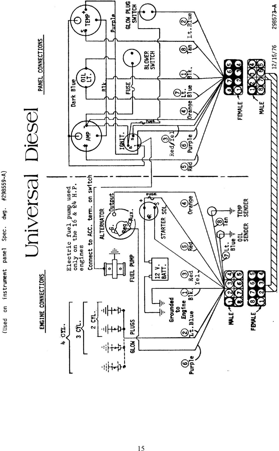
15 INSTRUMENT PANEL Refer to the instrument panel drawing when becoming familiar with the start up procedure or any general operating requirements of the engine. The Blower switch will remain in the ON position until it is turned off. The Glow Plug switch requires continuous pressure for whatever time it is necessary to activate the glow plugs. The Oil Pressure light will come on briefly when starting the engine but should go out after the engine starts. A low oil level in the engine crankcase or a serious oil leakage should be suspected if the light comes on at any other time during engine operation. The key switch is a four position selector type. Far left, ACCESSORY -- OFF --- ON -- START at the far right moving clockwise. The key will spring return to the ON position when released after start up. Operating temperature is approximately 170 o F to 185 o F on models 5416, 5424 and Operating temperature is approximately 135 o F to 150 o F on model The ammeter should indicate the charge required based on equipment and battery condition. 14

16 15
17 PREPARING THE ENGINE FOR WINTER STORAGE OR LAYUPS Proper preparation of your engine for storage will avoid damage and minimize expense when again placing your engine in service. LUBRICATION SYSTEM: 1. Before boat is lifted out of the water, run the engine until operating temperature is attained. 2. Stop engine after warm up and remove crankcase oil through the dipstick hole using hand sump pump designed for that purpose. Replace dipstick after oil has been removed. 3. Refill crankcase with new oil and replace filler cap. 4. Run engine again for about 5 minutes to distribute a protective film of clean oil to act as a rust preventive during storage. TRANSMISSION: (See transmission instructions) 1. Fill transmission completely with type A transmission oil. (You may just add to the existing oil or drain the old oil and completely refill with new transmission oil. 2. Be sure both drain and filler plugs are tight after draining or adding to the oil in the transmission. 3. Transmission is now ready for storage. SEA WATER COOLING SYSTEM: Models 5416, 5424, & 5432 OPTION #1 1. To drain sea water system, disconnect hose end at sea water pump that comes from heat exchanger. Lower free end of hose to a point approximately level with the front engine mount. This will allow the sea water to drain from heat exchanger and hoses. 2. Loosen 4 screws on the sea water pump cover plate. Tap the plate lightly to loosen it, this will allow pump to drain. 3. After pump has drained, apply a light coat of oil to protect pump and impeller during storage and replace cover. 4. Drain exhaust muffler and system separately. 16

18 OPTION # 2 USED IN PLACE OF DRAINING SEA WATER 1. Disconnect sea water inlet hose at sea cock shut off valve. BE SURE SEA INLET VALVE IS CLOSED. 2. Place this inlet hose into a container of antifreeze, after it has stopped draining, and crank engine over (with decompression lever on), at 10-second intervals, until antifreeze comes out of exhaust outlet, see item You should now have antifreeze in sea water pump, hoses, heat exchanger and exhaust system. 4. If aqua lift or pot type muffler is used, it is recommended to drain prior to pumping antifreeze thru system. SEA WATER COOLING SYSTEM: Model 5411 OPTION # 1 1. Open the cylinder block drain cock on the side of the block where hose from water pump enters, and drain. 2. Loosen water pump cover plate, allowing pump to drain, replace cover. 3. Remove drain plug on rear bottom of exhaust manifold, and drain. 4. When boat is out of water, inlet lines to pump and thermostat will drain. Close sea cock valve when completed for storage. 5. If aqua lift or can type muffler is used, it is recommended to drain muffler and lines of water. OPTION # 2 (With engine at operating temperature and stopped) 1. Shut off sea cock valve. 2. Remove hose at sea cock. Let water drain from hose. Place inlet hose into container of antifreeze (with decompression lever on). Crank engine over at 10-second intervals until antifreeze comes out exhaust outlet. 3. If aqua lift or can type muffler is used, drain prior to pumping antifreeze thru system. 4. You may wish to do option #1 prior to #2 to insure all water is out of engine and exhaust system. 5. Replace hose to sea cock when complete. Be sure sea valve is closed. 6. Antifreeze will aid in coating the inside of the engine, reducing rusting. 17

19 TO DRAIN FRESH WATER COOLING SYSTEM: Models 5416, 5424, and Remove pressure cap from manifold. 2. Open drain cock located above oil filter to drain engine block and cylinder head. 3. Open the in-line drain petcock located below the alternator. This will drain the manifold, heat exchanger and engine fresh water pump. 4. Remove 1/8 pipe plug at lower rear of manifold, to drain manifold separately. 5. Close all drain valves and petcocks when draining has been completed. 6. If antifreeze solution is used, it is not necessary to drain the system each year, providing you have the correct mixture to prevent freezing during winter storage. EXHAUST SYSTEM: 1. Exhaust pipes and muffler should be drained of sea water. Allow the exhaust pipes to dry out. Seal exhaust pipe end to prevent entrance of moisture into the engine through exhaust valves that are open. 2. See Option #2 under Sea Water Cooling System appropriate for your model. ELECTRICAL SYSTEM: 1. Remove battery and store it in a warm dry area. 2. Protect other electrical parts against moisture. FUEL TANK: 1. To protect against corrosion or moisture in the fuel supply tank, either fill the tank with fuel or drain completely and seal top securely for storage. GENERAL: You may want to completely cover the engine to provide additional protection. Care should be taken when covering so that electrical connections are not loosened and that fuel lines are not bent or broken. 18

20 PREPARING ENGINE FOR SPRING SERVICE Preparation of the engine should include all those items of maintenance necessary to permit satisfactory operation of the engine. A properly serviced engine will give a full season of carefree pleasure. The amount of service needed will be determined by the storage procedure of the previous fall. Refer to the section of the manual covering initial start up of the engine. LUBRICATION SYSTEM: 1. Drain oil from crankcase using hand sump pump through the dipstick hole. 2. Install new oil filter 3. Refill crankcase with recommended grade and amount of engine oil. (Fill to upper mark on dipstick). 4. Be sure filler cap is secure after filling crankcase and that no oil leaks are apparent. TRANSMISSION: 1. If transmission was completely filled for winter storage, some oil will have to be removed to attain the correct level in the transmission. 2. Check transmission oil level according to specifications found in this manual. 3. Be sure all plugs are secure and that no leaks are apparent. SEA WATER COOLING SYSTEM: 1. Remove front cover of pump if system was drained for storage. Inspect rubber impeller, lightly lubricate pump impeller, replace gasket and cover securely when inspection and lubrication have been completed. Turn grease cup 1/2 turn to lubricate shaft. 2. If impeller is not serviceable, see instructions covering the replacement of the sea water pump impeller in the maintenance section of this manual. COOLING SYSTEM: Model 541l On model 5411, make sure all plugs and hoses are replaced and secure. Remove hose on pump and add about 3/4 oz. of lube oil. This will lubricate impeller when engine first starts until it picks up sea water. 19
. 4. Be sure filler cap is secure after filling crankcase and that no oil leaks are apparent.")
21 FRESH WATER COOLING SYSTEM: Models 5416, 5424, and Inspect the heat exchanger and exhaust manifold for secure mounting and interior cleanliness. If system was filled with a 50/50 water and antifreeze mixture for storage, leaks will be easier to detect than if the system was drained. The coolant should be relatively clear and should be free of scale or other foreign particles. 2. If system was drained and inspection is satisfactory, fill slowly with coolant and replace pressure cap. Recheck coolant level after engine has run and reached operating temperature. Use caution when removing cap when engine is hot. EXHAUST SYSTEM: 1. Check all hoses and hose clamps for serviceability and security. Any worn or damaged hoses or clamps must be replaced before operation. 2. Check all valves and remove all plugs before operation. ELECTRICAL SYSTEM: 1. Inspect all wiring, terminals, controls and switches for damage or corrosion. 2. Install a fully charged battery and connect it correctly. (NEGATIVE GROUND). FUEL SYSTEM: 1. Fuel tank must be clean, free of water and securely mounted. If it was filled with fuel for storage, FUEL MUST BE CLEAN. 2. Check fuel cap vent hose. It must be open for unrestricted air venting. 3. Replace with new fuel oil filter. 4. Fuel lines must be secure and all clamps and nuts tight. Lines must not be bent or leaking. Fuel system will require bleeding before operation, if tank has been drained or filter has been replaced. (See instructions covering fuel system bleeding). 20
22 GENERAL: All of the above items must be carefully checked if satisfactory operation is to be expected. Refer to the start up check list in this manual after above items have been checked and before attempting to start the engine so that the proper procedure may be followed. With the boat in the water, check freedom of the propeller shaft in the bearings and alignment of the propeller shaft with the engine. Also, it may be necessary to tighten the stuffing gland just enough to stop excessive leakage along the shaft. Excessive tightening will cause power loss and burned stuffing material. A slight seepage is necessary to lubricate the stuffing gland. Any problems arising from this pre-use inspection requiring special tools or attention should be referred to a Medalist Universal Dealer service center, or a qualified diesel engine service center. 21
23 MAINTENANCE OF YOUR ENGINE Unless major repair work is done on the engine, timing should not be required. FUEL INJECTION TIMING: Basic tools required : (A) 10 MM Socket wrench (B) 13 MM Socket wrench (C) 17 MM Open end wrench (D) 12 MM Box end wrench (E) 27 MM Socket (1-1/16 ) Engine firing order : Two cylinder 1-2 (From V belt end) Three cylinder Four cylinder Remove fuel lines from injector pump fittings on injector pump (Tool C). 2. Pull decompression lever so that it will remain in the decompression position. 3. Open throttle fully. 4. Energize electric fuel pump and turn engine over with starter to ensure that fuel is coming out of each injector pump opening. Have clean rags around opening to soak up fuel. S. Wipe off any fuel on injector pump body and the top of each injector opening. 6. Turn crankshaft over by hand being careful not to damage spline on end of crankshaft. Engine rotation will be clockwise. STOP IMMEDIATELY at the first sign of fuel movement in the injector pump fuel fitting, for whichever injector pump is being checked. (No. 1 injector pump is the closest to the V-belt end of the engine). 7. Remove cover from flywheel timing mark inspection hold. Located inside of left engine mount (Tool B). 8. Check alignment of mark on flywheel with the timing pointer on the wall of the inspection hole. The 1-Fl mark on the flywheel represents fuel injection of No. 1 cylinder. 2-Fl represents No. 2 cylinder, etc. Continued over /
24 9. If timing pointer and the flywheel marking 1-Fl is aligned, then No. 1 cylinder is properly timed for fuel injection and should require no adjustment. The same will be true for No. 2, No. 3 and No. 4 cylinders if the above steps are followed. 10. In order to determine if timing is off, or if the injection pump is faulty, it is necessary to recheck the timing for each cylinder two or three times. 11. If there are variations in repeatability in the alignment of pointer and timing mark, a faulty fuel injector pump may be suspected. 12. If timing marks repeat to same location but are off 3/16 or more above or below the pointer, this indicates that the engine must be retimed. If alignment of the timing mark is not within 3/16 above or below the pointer, the above steps must be taken to time the engine. If the timing is found to be satisfactory, then reconnect all fuel lines and fittings and tighten. The fuel system must be bled before the engine will operate properly. (See fuel bleeding instructions on page 28). 23
25 DIESEL VALVE TIMING Fig. 17. Adjustment of Valve Clearance Intake valve opens 20 o B TDC Intake valve closes 45 o A BDC Exhaust valve opens 50 o B BDC Exhaust valve closes 15 o A TDC Valve clearance: to in. (0.18 to 0.22 mm) With engine cold. Turn crankshaft over by hand (Clockwise) being careful not to damage the spline on the end of the shaft. Turn until pointer aligns with timing mark 1TC on flywheel. Check to make sure both intake and exhaust valves on No. 1 cylinder are loose. If not, turn crankshaft one more complete revolution to bring No. 1 cylinder onto compression. Valves can now be set on No. 1 cylinder. This procedure is true for No. 1 cylinder on both the two and three cylinder models. To set the valves on the remaining cylinders, follow the respective diagrams above being sure that both intake and exhaust valves are loose at the respective cylinder before adjusting. CAUTION: DO NOT USE THE TIMING MARKS 1-Fl, 2-Fl, etc. THESE MARKS ARE USED FOR TIMING FUEL INJECTOR PUMPS ONLY. 24
26 ADJUSTING FUEL TIMING Steps necessary for fuel timing: 1. Remove air intake manifold so that the fuel injector pump can be removed without interference. 2. Remove injector pump side cover. This will enable you to visually check to insure that the fuel rack pin inside the pump properly aligns with the opening in the top of pump housing when being removed to prevent binding or shearing of the pin. This pin is critical to proper pump operation and if damaged will require replacement of the complete pump. 3. The injector pump internal unit can now be loosened and removed. It may be necessary to remove fuel lines from injector nozzles to aid in pump removal. 4. There are several shims located just below the pump top plate which will be used to adjust the timing. These shims are.006 inch thick and are equal to l - ½ o or approximately 3/16 of distance on the circumference of the flywheel. Addition of shims will retard the timing and removing shims will advance the timing. S. If the mark on the flywheel is below the pointer, the fuel is being injected soomer than required and the fuel timing must be retarded. Shims must be added until the timing marks are aligned. The opposite is true if the flywheel mark is above the pointer. 6. If at all possible, it is better to operate the engine with the timing advanced rather than retarded. 7. Replace fuel injector pump, making sure the fuel rack pin aligns with the housing opening and is properly inserted into the slotted arm. Tighten injector pump cover in place. Reconnect fuel line from fuel filter to pump. Repeat steps 2 thru 12 on engine timing. 8. If timing is satisfactory, then reassemble. Be certain that all plates, covers, fuel lines and connections are tight and free of leaks so that safe operation may be expected when the engine is started. Clean engine thoroughly. 9. Caution: Be sure all fuel lines and connections are kept clean during adjusting, to prevent fouling of nozzles when reassembled. 25
27 DECOMPRESSION DEVICE ADJUSTMENT: The decompression device must be adjusted every time the rocker arm cover is removed or tightened. 1. Remove cover over flywheel timing mark inspection hole. (Tool B). 2. Turn crankshaft over by hand being careful not to damage the spline on end of crankshaft, until flywheel mark 1-TC is aligned with the pointer On the wall of the inspection hole. 3. Remove decompression covers from top of rocker arm cover over number 1 cylinder. (Tool A). 4. With the alignment of the pointer and flywheel mark l-tc the No. 1 cylinder decompression adjustment can now be accomplished. 5. Pull and hold lever to full decompression position. 6. Working through the access hole, loosen the lock nut with a wrench (Tool A) and back the adjusting screw off until no contact is made on the rocker arm (Using screw driver). 7. Now turn adjusting screw in until first contact is made, continue to turn screw in (1) turn. 8. Lock the screw in this position with the lock nut. Observe the position of slot in screw prior to locking nut, recheck after tightening lock nut. 9. The above steps are to be followed to adjust the decompression for all remaining cylinders. After aligning the respective flywheel marks (2-TC, 3-TC, etc.), adjustments can be made as described in steps 3 thru 7 above. 10. After all necessary adjustments have been made, be sure to replace and secure all access hole covers and the flywheel inspection hole cover. 26
28 FUEL SYSTEM: The fuel system utilizes an electric fuel pump, fue l filter, fuel injection pump with injectors and fuel lines. Any fuel not used by the injectors is returned through fuel return lines from the rear most nozzle to the top of the fuel supply tank. The canister type fuel filter should be changed each season before the engine is placed back in service or more often based on engine usage. The engine operates on No. 2 diesel fuel only and care should be taken to see that no water or dirt enters the fuel system. Clean fuel is very important to a smooth, trouble free running engine. 27
29 BLEEDING THE FUEL SYSTEM: It will be necessary to bleed the fuel system to achieve a steady air free flow of fuel if any of the following have occurred: 1. Running out of fuel. 2. If fuel shut off valve is left closed and engine runs out of fuel. 3. Replacing fuel filter. 4. Fuel injector nozzle or injector pump repair. 5. After repairing or replacing any fuel line. 6. Before putting engine back into service in the spring, if fuel system has been drained. 7. Replacement of electric or mechanical fuel pump. 8. Any time air is permitted to enter the fuel system. BLEEDING PROCEDURE: Be sure to have some means available to catch or absorb any fuel escaping during the bleeding process so that it will not accumulate in the engine compartment or bilge. 1. Be sure there is a sufficient supply of fuel in the fuel tank. 2. Open the fuel shut-off valve at the tank. 3. Start the electric fuel pump by turning the ignition key to the ACCESSORY position on models 5416 and Models 5411 and 5432 have mechanical fuel pumps. Therefore, with decompression on, turn engine over with starter. Crank at 10 second intervals while doing steps 5 and Slowly loosen the air bleed plug on the fuel filter, letting air escape until an air free flow of fuel is evident. 6. At this time, tighten the air bleed plug on the filter. 7. Slowly loosen the air bleed plug on the injector pump, letting air escape until an air free flow of fuel is evident. 8. At this time, tighten the air bleed plug on the injector pump. 9. The fuel system should now be properly bled and ready for operation. Refer to starting instructions before attempting to start the engine after bleeding the fuel system. 28
30 FUEL INJECTORS: Fuel injectors should be removed and taken to a qualified diesel engine repair center to be tested for leakage and spray pattern, if poor engine performance such as, loss of power, rough or uneven running, sudden notice of dark exhaust, or engine becomes hard to start. REMOVING INJECTORS: 1. Clean the area around the injectors before removing. 2. Loosen nuts holding fuel lines to injector pump and injector nozzles and remove fuel lines (Tool C). 3. Loosen nuts on return line adaptors and remove adaptors (Tool C). 4. Loosen injectors using (Tool E) and remove injectors. REPLACING INJECTORS: 1. Check to be sure contact surfaces and area around injectors is clean. 2. Replace injectors in the same cylinder from which they were removed. 3. Torque required to properly seat the injectors will be between 43 and 58 ft./lbs. 4. Replace fuel return lines and secure nuts. 5. Replace all fuel lines and secure all nuts. 6. After all injectors, fuel lines and hoses have been replaced and are secured, the fuel system will have to be bled. (Refer to bleeding instructions in this manual). The fuel injection pump has been set at the factory and should need no adjustment. Any apparent problem with the pump should be referred to a qualified diesel mechanic or to a Universal Diesel dealer as advised. NOTE: NO WARRANTY COVERAGE WILL BE GRANTED IF ANY OF THE FACTORY SET AND SEALED FUEL AND MAXIMUM RPM. ADJUSTMENTS ARE ALTERED. 29
31 VALVE ADJUSTMENT: The best performance and life of the engine may be achieved by maintaining optimum valve clearances at all times. 1. Remove rocker arm cover and rotate crankshaft so that the flywheel mark for the given cylinder is aligned with the pointer on the wall of the timing inspection hole. The inspection hole cover must be removed. 2. Loosen lock nut on the rocker arm adjusting screw and turn screw in so that it just makes contact with the push rod. 3. Now back screw out to obtain.008 inch clearance (2mm) Screw thread pitch =.040 (1mm) - one turn of screw. 4. After adjustment is made, be certain lock nut is securely tightened. 5. Decompression device will require readjustment after valve adjustment procedure has been completed. Valve clearance 1) Make measurements and adjustments while the engine is cold. 2) Measurement must be made when each cylinder is at compression TDC. 3) Insert the specified thickness gauge between the valve stem end and the tip of rocker arm. 30
32 OIL FILTER CHANGE: After draining engine oil and before refilling with new oil, the oil filter should be changed. 1. Unscrew old filter. If it will not loosen, use a special oil filter removal tool. 2. Take care to catch any escaping oil so that it will not accumulate in the engine compartment. 3. When installing new filter, moisten the rubber seal with oil, screw new oil filter onto the threaded shaft and tighten it. Hand pressure is sufficient to tighten the filter1. 4. Refill the crankcase with the correct grade and amount of oil as indicated by the dipstick. S. Start the engine according to the starting procedure in this manual. Run only long enough to check for any oil leaks and stop engine. 6. The oil level will have dropped by the amount of oil which enters the oil filter and by the amount which has distributed around the engine. 7. After engine has stopped and the oil level allowed to settle, recheck the oil level and fill as required. 31
33 SEA WATER PUMP Your engine is equipped with a rubber impeller type sea water pump. Do not run pump dry at any time or you will damage the impeller, causing engine to overheat. You can use methyl alcohol based anti-freeze compounds such as Zerex, Shell Zone, Pyro Permanent, Permagard and Dowgard. REPLACEMENT OF SEA WATER PUMP IMPELLER 1. Be sure engine is stopped. Turn off sea water inlet valve. 2. Loosen and remove the four pump cover screws. 3. Tap cover on side to loosen, being careful not to damage cover gasket and remove cover. 4. At this time, be careful to not pull the pump shaft forward or out of its present position. If the shaft does come forward during the changing of impeller, it will be necessary to remove complete pump. S. Remove the snap ring located on the end of shaft in center of impeller, with shaft held in place. 6. The impeller can now be pulled off the pump shaft. Be sure to hold shaft in place with a screwdriver or etc. when removing the impeller. 7. Replace with the new impeller by rotating. (You can lubricate impeller with vasoline or oil prior to installing). This will also prevent burning of new impeller when first starting engine. 8. Replace snap ring, being sure it is in the groove all the way around. 9. Replace gasket and cover (oil inside of cover). 10. Replace the four cover screws and tighten evenly. 11. Open sea water inlet valve, check for leaks. 12. Engine can now be started, check engine temperature. IF DURING THIS REPLACEMENT, THE PUMP SHAFT CAME FORWARD, IT COULD HAVE COME OUT OF THE GROOVE AND DRIVE ADAPTOR. IF SO, YOU MUST COMPLETE THE FOLLOWING: 1. Loosen and remove the two capscrews holding the pump body to engine. 2. Slowly move pump away from engine as the adaptor will come out. 3. Complete the replacement of impeller as noted above. 4. The pump shaft will now be protruding through the body mounting flange. 5. Place the adaptor on to the pump shaft aligning the pin on the groove. 32
34 6. Align the slot on the other side of adaptor with the drive shaft in engine and place pump on engine. 7. Hold in place and start the two mounting capscrews. Tighten finger tight so pump is free to move a little and align itself. 8. Turn on sea water valve and start engine. This will align pump to the drive and adaptor. 9. Now tighten capscrews carefully while engine is running, being very careful due to V- belt moving. 10. Feel the bearings to make sure they are not hot; located in center of pump body where grease cup is located. 33
35 RUBBER IMPELLER PUMP PARTS OF SEA WATER PUMP 1. Cover Screws (4) 8. Cam Locking Screw 2. Pump Cover 9. Pump Body 3. Cover Gasket 10. Water Seal 4. Impeller Snap Ring 11. Oil Seal 5. Impeller 12. Drive Adaptor 6. Pump Shaft 13. Grease Cup 7. Cam 14. Drain Plug - CAUTION - DO NOT RUN PUMP DRY. EXCESSIVE HEAT CAUSED BY OPERATING PUMP DRY WILL DESTROY THE RUBBER IMPELLER. 34
36 MODEL 5411 SEA WATER CIRCULATION Normal Range 135 o F to 150 o F 1. Sea water enters through sea water inlet, 2. Through sea water valve when open, 3. Into mixing tee to suction side of pump, located below water line. 4. Out of pump by hose to inlet on side of block, 5. Circulates through block into cylinder head, 6. Leaves head on top front to exhaust manifold, 7. Circulates through manifold to thermostat, 8. Enters thermostat which remains closed during warm up, permitting a small amount of water to enter exhaust system for cooling and overboard. 35
37 9. As engine temperature rises the thermostat starts to open, letting hot water enter exhaust line. At the same time the same amount of cool sea water is drawn in by the pump to replace the discharged hot water. This is done through the mixing tee which is located below engine (or water line) to prevent air from entering the system. 10. There may be some fluctuation in engine temperature until engine stabilizes. 11. In areas of cold inlet say 50 o F, you may notice some movement from 136 o F to 155 o F as engine r.p.m. are changed. This is less noticeable with warmer inlet waters. The reason being that the colder water causes thermostat to react faster than engine temperature stabilizes. 36
38 MODEL 5416, 5424 AND 5432 SEA WATER AND FRESH WATER CIRCULATION DIAGRAM NORMAL RANGE F to l85 0 F SEA WATER: 1. Sea water enters through sea water inlet. 2. Through sea water valve when open. 3. Through sea water pump into heat exchanger to cool fresh water system. 4. From heat exchanger to sea water overboard through exhaust port. 37
39 FRESH WATER: 1. Coolant (fresh water) is introduced to system by filling coolant section of exhaust manifold by removing pressure cap and filling tank to within one inch of lower rim of fill port. 2. Fresh water engine driven pump pulls coolant from heat exchanger through engine block and thermostat back through exhaust manifold and into heat exchanger to be cooled. 38
40 UNIVERSAL DIESEL TRANSMISSION Model HBW-5 (2:1) Model HBW-10 (2.14:1) TABLE OF CONTENTS A. Description B. Servicing C. Maintenance D. General Information E. Illustrations 39
41 A. DESCRIPTION: The Hurth transmission housing is made of a high strength aluminum alloy that is resistant to sea water. The transmission is equipped with shaved and case hardened helical gears and with shafts mounted in heavy-duty roller bearings. Forward and reverse is accomplished by a mechanical friction clutch. Gear shifting is mechanical and requires only a minimum effort on the gear lever. Precision setting or readjustment of the shifting control (Morse or Teleflex) is not required. The transmission is designed to permit reversing at full engine speed. TO BE USED ONLY IN THE EVENT OF AN EMERGENCY! B. SERVICING: The transmission is filled with Type A transmission fluid at the factory during the engine load test. Recheck and fill the gear box with the prescribed oil up to the top mark on the dipstick. When checking the oil level, DIPSTICK TO BE INSERTED ONLY - DO NOT SCREW IN. Tighten the dipstick after adding oil or checking the oil level. 1. Placing in service after storage. If the transmission was completely filled with oil for for storage and preservation, make sure to drain the excess oil to the proper level. Use new oil if necessary. 2. Oil quantity. Approximately 1.3 pints (.55 liter) - see servicing. 3. Oil grade. Automatic Transmission Fluid, Type A. ALWAYS USE THE SAME GRADE AND TYPE OF OIL WHEN ADDING OR CHANGING OIL. WARNING: ADDITIVES SUCH AS MOYBDENUM SULPHITE OR THE LIKE MUST NOT BE CONTAINED IN THE OIL UNDER ANY CIRCUMSTANCES. 40
42 C. MAINTENANCE: 1. Oil level in the transmission should be checked weekly. Oil level: See Servicing. 2. Changing oil. Change oil after first 25 hours of operation. Then change every 300 hours of operation, or at least at intervals of once a year or season. 3. Placing transmission in storage. If the transmission is put out of operation for long periods of time under unfavorable environmental conditions, it should be protected against corrosion by filling it completely with oil of the same grade and type. Otherwise, it should be operated briefly with a good oxidation inhibiting oil to allow the agent to contact all parts of the gearbox. D. GENERAL INFORMATION: 1. General If the transmission is being painted, care should be taken to protect the oil seals at the output shaft in back of the coupling. Make sure the venting hole on the oil filter screw is not covered with paint. The assembly - (engine/transmission) should be flex mounted in the boat to avoid distortion of the transmission housing. 2. Angle of installation The angle of installation must not exceed 15 o in relation to the water line in operation. (See illustration Fig. 3). 3. Operating temperature Proper ventilation of the engine and transmission compartment should be insured. The operating temperature of the transmission oil should not exceed 250 o F. (130 o C). 4. Flexible couplings The flex coupling between engine coupling and propeller shaft should be designed to absorb bending stresses to compensate for minor angular deviations after installation. Coupling alignment should be rechecked with the boat in the water. 41
43 5. Gear shifting Shifting requires little effort, therefore, the single lever control works well on this transmission. Shift lever: Upon loosening the retaining screw (3), the shifting lever, item (2), can be rotated as required to meet the control cable connection. The operating cable or rod assembly should be positioned perpendicular to the shifting lever in its neutral position (Fig. 3) The shifting travel, measured at the pivot point of the shifting lever, must be at least 1 (35mm) from neutral to forward and neutral to reverse position. Longer shifting movements have no detrimental effect on the transmission (Fig. 2). When shifting transmission, engine R.P.M. should be rechecked to idle, then shift transmission firmly from one direction to another. A slight pause in neutral will allow propeller to slow and add life to transmission. When running the engine to charge batteries in neutral, engage transmission for 1 or 2 minutes every 2 or 3 hours to lubricate all internal parts. Transmission can be left in neutral when sailing. 42
44 HURTH TRANSMISSION ILLUSTRATIONS: 43
45 PERIODIC SERVICE CHART Always be sure engine is stopped and cool and that your personal safety is considered before making checks or doing any repair work. PERIOD OF OPERATION THINGS TO DO Break-in period (Approx 10 hours at 75% cruise speed) Change engine oil, filter and transmission oil after first 25 hours. Always allow engine to warm up before applying load. Every 75 hours Change engine oil and oil filter or at least once each season. Every 100 hours Check V-belt tension. ½ deflection Check electrolyte levels in battery. Every 300 hours. Change fuel oil filter and transmission oil or once each year which ever comes first. This manual subject to modifications without notice. 44
46 MARINE ENGINE WARRANTY - LIMITED PRODUCT WARRANTY Seller warrants all products and parts of its own manufacture against defects in material or workmanship for a period of one (1) year from date of shipment when given normal and proper usage as determined by seller upon examinations, and when owned by the original purchaser. Components purchased by seller as complete units and used as an integral part of sellers equipment will be covered by the standard warranty of the manufacture thereof. Seller will repair or replace F.O.B. original shipping point (but not install) any part or parts of its manufacture which in its judgment, shall disclose defects in either material or workmanship. If requested by seller, parts for which a warranty claim is made are to be returned transportation prepaid to our factory. This warranty becomes void if article claimed to be defective has been repaired or altered in any way or when the article has been subject to misuse, negligence or accident, or when instructions for installing or operating has been disregarded. WE MAKE NO OTHER WARRANTY, EXPRESS OR IMPLIED, AND MAKE NO WARRANTY OR MERCHANTABILITY OR OF FITNESS FOR ANY PARTICULAR PURPOSE, AND THERE ARE NO WARRANTIES WHICH EXTEND BEYOND THE DESCRIPTION ON THE FACE HEREOF. NO EMPLOYEE OR REPRESENTATIVE IS AUTHORIZED TO CHANGE THIS WARRANTY IN ANY WAY OR GRANT ANY OTHER WARRANTY. THE REMEDIES HEREIN ABOVE AFFORDED TO THE PURCHASER ARE EXCLUSIVE OF ALL OTHER REMEDIES PROVIDED BY LAW. SELLER SHALL NOT BE LIABLE FOR INDIRECT OR CONSEQUENTIAL DAMAGES WHERE THE LOSS SUSTAINED IS OF A COMMERCIAL NATURE. PRODUCT IMPROVEMENTS The Manufacturer reserves the right to make product improvements at any time without responsibility or obligation to make similar changes or add similar improvements on engines delivered prior to those changes. WARRANTY REGISTRATION Enclosed with each engine is a warranty registration card. This card must contain the owner s name, address, serial number and model number of the engine and be returned to Medalist before the warranty becomes effective. Warranty registration will assist in identifying components required for your engine. WARRANTY EXCLUSIONS The following services or expenses will not be reimbursed under the warranty: 1. Tune up of the engine. 2. Repairs as a result of neglect, misuse, improper application, accident, racing of the engine and installations that do not meet minimum standards as set forth in the instruction manual. 3. Adjustments needed for cleaning of fuel system and compenents due to contamination. 4. Standard reverse gear adjustments from normal usage or wear. 5. Moisture in engine from exhaust systems which permit condensation or back flow of moisture into the engine. 45
47 6. Damage or loss to personal property, loss of revenue, towing charges, storage fees, fuel and telephone calls. 7. Damages or losses related to handling and shipping. 8. Expenses related to replacement of lubricants, anti-freeze or special addit ives. 9. Failure due to not following recommended maintenance schedules. 10. All transportation charges will be the obligation of the owner, such as freight, travel, time and tolls. 11. Warranty items returned to the factory collect will be billed to the shipper. WARRANTY AUTHORIZATION All repairs and/or claims must be approved by Medalist Universal Motors prior to performance of work. RETURN OF MATERIAL TO THE FACTORY All material to be returned must be authorized in advance by Medalist Universal Motors. Contact the service department for assignment of a return goods number. Ship material on a prepaid basis, after receiving the return goods form. PLEASE NOTE ENGINE WARRANTY REGISTRATION CARD MUST BE REUTRNED TO MEDALIST UNIVERSAL MOTORS IMMEDIATELY. GENERAL Medalist Universal distributors and dealers are located throughout the United States and Canada. Distributors and dealers have an ample inventory of parts and can provide prompt, expert service in the maintenance and repair of your engine. Medalist Universal Service Department will also provide assistance, within the limits of our specifications. Welcome to the Medalist Universal Diesel powered sailing fleet. Universal Motors Universal Motors 1552 Harrison St P.O. Box 2508 Oshkosh, WI (414) Cable: Unimot TLX
ENGINE COOLING SYSTEM
 ENGINE COOLING SYSTEM 1988 Toyota Celica 1987-88 TOYOTA Engine Cooling Systems Celica DESCRIPTION The basic liquid cooling system consists of a radiator, water pump, thermostat, cooling fan, pressure cap,
Cooling system components, removing and installing
 Engine BHW Cooling system components, removing and installing Page 1 / 24 19-1 Cooling system components, removing and installing Warning! When doing any repair work, especially in the engine compartment,
Trouble Shooting. Pump
 Trouble Shooting Pump Trouble Possible Cause Remedy Oil leaking in the area of water pump crankshaft Worn crankshaft seal, bad bearing, grooved shaft, or failure of retainer o-ring. Excessive play on crankshaft
Volkswagen Jetta, Golf, GTI 1999, 2000 2.8 Liter VR6 2V Engine Mechanical, Engine Code(s): AFP 17 Engine-Lubrication (Page GR-17)
: AFP 17 Engine-Lubrication (Page GR-17)") 17 Engine-Lubrication (Page GR-17) Lubrication system components, removing and installing Oil filter housing, disassembling and assembling Oil pan, removing and installing Oil pressure and oil pressure
17 Engine-Lubrication (Page GR-17) Lubrication system components, removing and installing Oil filter housing, disassembling and assembling Oil pan, removing and installing Oil pressure and oil pressure
Cooling system components, removing and installing
 Page 1 of 34 19-1 Cooling system components, removing and installing WARNING! The cooling system is pressurized when the engine is warm. When opening the expansion tank, wear gloves and other appropriate
Fuel Injection Pump, Rotary (005-014)
") Fuel Injection Pump, Rotary View Related Topic Page 1 of 30 Fuel Injection Pump, Rotary (005-014) Table of Contents Summary General Information Preparatory Steps Remove Front Gear Train Rear Gear Train
Fuel Injection Pump, Rotary View Related Topic Page 1 of 30 Fuel Injection Pump, Rotary (005-014) Table of Contents Summary General Information Preparatory Steps Remove Front Gear Train Rear Gear Train
CDS TROUBLESHOOTING SECTION I. VACUUM. 1.0. Weak vacuum at wand. Gauge reads normal (10hg to 14hg)
") CDS TROUBLESHOOTING SECTION I. VACUUM 1.0. Weak vacuum at wand. Gauge reads normal (10hg to 14hg) 1.1. Clogged hoses or wand tube. Disconnect hoses and carefully check for an obstruction. 1.2. Excessive
CDS TROUBLESHOOTING SECTION I. VACUUM 1.0. Weak vacuum at wand. Gauge reads normal (10hg to 14hg) 1.1. Clogged hoses or wand tube. Disconnect hoses and carefully check for an obstruction. 1.2. Excessive
Rexroth Hydraulic Pump A10VO Series User Manual
 Rexroth Hydraulic Pump A10VO Series User Manual Rexroth Hydraulic pump A10VO Series User Manual Revised 5/1/2009 Page 1 of 12 Functional Purpose This pump is preferred over a fixed displacement (gear)
Volkswagen Jetta, Golf, GTI 1999, 2000 Brake System 47 Brakes - Hydraulic Components (Page GR-47)
") 47 Brakes - Hydraulic Components (Page GR-47) FS III front brake calipers, servicing Front brake caliper piston, removing and installing FN 3 front brake calipers, servicing Front caliper piston, removing
47 Brakes - Hydraulic Components (Page GR-47) FS III front brake calipers, servicing Front brake caliper piston, removing and installing FN 3 front brake calipers, servicing Front caliper piston, removing
STEERING SYSTEM - POWER
 STEERING SYSTEM - POWER 1990 Nissan 240SX 1990 STEERING Nissan - Power Rack & Pinion Axxess, Maxima, Pulsar NX, Sentra, Stanza, 240SX, 300ZX DESCRIPTION The power steering system consists of a rack and
ENGINE FUEL FUEL FILTER... FUEL HEATER... INJECTOR... SUPPLY PUMP... COMMON RAIL... FUEL PRESSURE LIMITTER...
 FUEL FILTER............................ FUEL HEATER.......................... INJECTOR.............................. SUPPLY PUMP.......................... COMMON RAIL.......................... FUEL PRESSURE
SLP 1.85 Ratio Offset Rocker Arms with Valve Springs, LS3
 PART #50190 SLP 1.85 Ratio Offset Rocker Arms with Valve Springs, LS3 PACKING LIST Before installation, use this check list to make sure all necessary parts have been included. ITEM QTY CHECK PART NUMBER
Volkswagen Golf 5 2004-> VW Rabbit GTI 2006->
 Стр. 1 из 24 Volkswagen Golf 5 2004-> VW Rabbit GTI 2006-> 19-1 Cooling system components Warning! Hot steam may escape when opening expansion tank. Wear protective goggles and protective clothing to prevent
BOWIE PUMPS OPERATION - MAINTENANCE
 BOWIE PUMPS OPERATION - MAINTENANCE PUMPING PRINCIPLE: The meshing owieeof the gears cause a slight depression, with the resulting enmeshing of the gears causing a vacuum drawing the fluid being pumped
Turbocharger system components, servicing
 21-1 Turbocharger system components, servicing Engine codes: AAZ, 1Z, AHU Observe rules of cleanliness Page 21-10 Turbocharger hoses and lines, connecting Page 21-11 WARNING! Do not re-use any fasteners
VOLVO PENTA DIESEL AND GASOLINE ENGINES LAYING-UP AND LAUNCHING GUIDE
 VOLVO PENTA DIESEL AND GASOLINE ENGINES LAYING-UP AND LAUNCHING GUIDE TIME WELL INVESTED This guide covers most of the items to be checked and seen to on your engine and drive when laying up and launching.
www.servicechamp.com
 1-800-221-0216 Fax: 1-800-472-2281 www.servicechamp.com Service Champ Part 52081 Service Interval every 30,000 miles / Chevrolet 1992-2002 6.5 liter Description and Operation The fuel filter element separates
Volkswagen New Beetle 2.0 Liter 4-cyl General, Engine (Engine Code AEG) 17 Engine-Lubrication system (Page GR-17)
 17 Engine-Lubrication system (Page GR-17)") 17 Engine-Lubrication system (Page GR-17) Lubrication system components, removing and installing Oil pan, removing and installing Oil pressure and oil pressure switch, checking Dynamic oil pressure warning
17 Engine-Lubrication system (Page GR-17) Lubrication system components, removing and installing Oil pan, removing and installing Oil pressure and oil pressure switch, checking Dynamic oil pressure warning
Draining and filling cooling system
 Page 1 of 9 Draining and filling cooling system Special tools and workshop equipment required Adapter -V.A.G 1274/8- Pipe -V.A.G 1274/10- Drip tray -V.A.G 1306- or drip tray for workshop hoist -VAS 6208-
2740 Whitten Rd Bldg 103 Memphis, TN 38133 Telephone 901-380-9290 Email [email protected]
 Fuel Injection Pump Replacement REMOVAL Diesel Care & Performance Inc 1. Disconnect negative battery terminal. 2. Remove throttle linkage. Fuel Injection Pump Bracket 3. Remove injection pump bracket.
Tri-Homo Style Operation and Maintenance Instructions
 Tri-Homo Style Operation and Maintenance Instructions One Research Drive Stratford, CT 06615 (203) 375-0063 www.sonicmixing.com 1 Installation and Start-up Do not perform following adjustments without
BUT PRECAUTIONS MUST BE TAKEN OR SERIOUS BURNS CAN RESULT.
 Cooling System Operation Below is an explanation of this system's operation Radiator The radiator is a device designed to dissipate the heat which the coolant has absorbed from the engine. It is constructed
Table of Contents. Overview 1. Pump Disassembly 2. Control Disassembly / Reassembly 7. Pump Reassembly 13. Adjustment Procedures DR Control 19
 Table of Contents Overview 1 Pump Disassembly 2 Control Disassembly / Reassembly 7 Pump Reassembly 13 Adjustment Procedures DR Control 19 Adjustment Procedures DRG Control 20 Adjustment Procedures DFR
300 SERIES 331, 332, 333, 344, 356 AND 367 MODELS
 Section: MOYNO 500 PUMPS Page: 1 of 8 Date: March 1, 1998 SERVICE MANUAL MOYNO 500 PUMPS 300 SERIES 331, 332, 333, 344, 356 AND 367 MODELS Mechanical Seal Models Packing Gland Models MODELS DESIGN FEATURES
Section 7 Adjustment, Repair and Replacement
 Section 7 Adjustment, Repair, and Replacement Page 7-1 Section 7 Adjustment, Repair and Replacement Section Contents Page Overview...7-5 Belts Belt Guard Removal/Installation...7-7 Belt Removal/Installation...7-11
Cooling system components, removing and installing
 Volkswagen Touareg 3.2 - Cooling system components, removing and installing Page 1 / 24 19-1 Cooling system components, removing and installing Warning! Hot steam may escape when opening expansion tank.
REMOVAL AND INSTALLATION
 303-01C-1 REMOVAL AND INSTALLATION Engine Body On Special Tool(s) Adapter For 303-D043 303-D043-02 or equivalent Special Tool(s) 303-01C-1 Turbocharger Lifting Bracket 303-1266 Wrench, Fan Clutch Nut 303-214
PREVENTION MAINTENANCE CHECKLIST FOR TRACTORS, TRUCKS, AND AUTOMOBILES
 PREVENTION MAINTENANCE CHECKLIST FOR TRACTORS, TRUCKS, AND AUTOMOBILES Farm Machinery Fact Sheet FM-21 By Dr. Von H. Jarrett, Extension Agricultural Engineer Systematic sequence for inspection GASOLINE
WHAT YOU DON T KNOW ABOUT ACCUMULATORS CAN KILL YOU!
 WHAT YOU DON T KNOW ABOUT ACCUMULATORS CAN KILL YOU! Atlanta (Monroe) GA 770-267-3787 [email protected] www.gpmhydraulic.com What You Don t Know About Hydraulic Accumulators Can Kill You TABLE OF CONTENTS
3620 W 11th Streetб Houston, TX 77008 Telephone: 713-635-6291 Email: [email protected] Website: www.kellogg-american.com
 Unpackaging & Handling Be sure to carefully inspect the unit before accepting the shipment. If any damage has occurred document it with the trucking company immediately. Contact your Kellogg Distributor
P7100 PUMP INSTALLATION INSTRUCTIONS Diesel Care & Performance Inc
 P7100 PUMP INSTALLATION INSTRUCTIONS Diesel Care & Performance Inc Installation Timing Pin Location CAUTION: Before installing the injection pump, be sure that number 1 cylinder is at the Top Dead Center
SunMaxx Solar Filling Station Operating Instructions
 SunMaxx Solar Filling Operating Instructions Content 1. Declaration of conformity... 2 2. Introduction... 2 3. Transportation and unpacking... 4 4. Mounting and commissioning... 5 5. End of operation...
Oregon Fuel Injection
 Corporate Office: P.O. Box 21121, VE Pump Removal and Installation Cummins Lock Timed Applications Removal Clean the exterior of the injection pump and mounting surfaces. 1. Disconnect the fuel return
How To Fix A Car With A Carbide Engine
 Section 12 Adjustment, Repair, and Replacement Page 12-1 Section 12 Adjustment, Repair and Replacement Section Contents Page Overview...12-5 Belts Belt Guard Removal/Installation...12-7 Belt Removal/Installation...12-11
11. COOLING SYSTEM 11-0 COOLING SYSTEM BET & WIN 50
 11 COOLING SYSTEM SERVICE INFORMATION------------------------------------------------ 11-1 TROUBLESHOOTING----------------------------------------------------- 11-1 RADIATOR ------------------------------------------------------------------
FJ2. 2 Ton Trolley Floor Jack Assembly & Operating Instructions
 FJ2 2 Ton Trolley Floor Jack Assembly & Operating Instructions READ ALL INSTRUCTIONS AND WARNINGS BEFORE USING THIS PRODUCT. This manual provides important information on proper operation & maintenance.
System Saver 318 Air Compressor for Mack E-Tech and ASET Engines
 Maintenance Manual 31 System Saver 318 Air Compressor for Mack E-Tech and ASET Engines Revised 08-05 NON-THROUGH DRIVE THROUGH DRIVE Service Notes About This Manual This manual provides service and repair
123 Industrial Loop Road Paynesville, MN 56362 Phone: 1-800-864-1649 www.master-mfg.com MASTER MANUFACTURING MASTER GARDNER
 123 Industrial Loop Road Paynesville, MN 56362 Phone: 1-800-864-1649 www.master-mfg.com MASTER MANUFACTURING MASTER GARDNER Part Number PCD E3 009B MM Rev 1 Nov. 2010 INTRODUCTION The purpose of this manual
TABLE OF CONTENTS. Section 1 - Assembling your new pit bike.
 Orion Pit Bike Sales Owners Manual (All information and content is the property of Orion Pit Bike Sales. Any attempt to copy or resell is a direct violation of our copyright. All violators will be prosecuted)
Float and Thermostatic Traps Series H, C and X
 Hoffman Specialty Installation & Maintenance Instructions HS-(E) and Thermostatic Traps Series H, C and X Series C & NPT Series C NPT Series X NPT Series C NPT Series H Ratings Maximum Max. Operating NPT
Chapter 7 Hydraulic System Troubleshooting
 Chapter 7 Hydraulic System Troubleshooting General The following troubleshooting information is provided as a general guide to identify, locate and correct problems that may be experienced with the hydraulic
SELF-STEERING AXLE TABLE OF CONTENTS
 SELF-STEERING AXLE TABLE OF CONTENTS Section 1 - Introduction Section 2 - Pre-Installation Check List Section 3 - Ride Height Adjustments Section 4 - Suspension Mount Section 5 - Axle Mount Section 6 -
13. REAR WHEEL/BRAKE/SUSPENSION
 13. REAR WHEEL/BRAKE/SUSPENSION 13 3.5~4.5kg-m 8.0~10.0kg-m 0.8~1.2kg-m 3.0~4.0kg-m 2.4~3.0kg-m 3.5~4.5kg-m 6.0~8.0kg-m 13-0 13. REAR WHEEL/BRAKE/SUSPENSION 13 REAR WHEEL/BRAKE/SUSPENSION SERVICE INFORMATION...
Adjustment Data MAZDA - 626-2.0 Comprex D - RF-CX
 Adjustment Data MAZDA - 626-2.0 Comprex D - RF-CX Engine (general) Engine code RF Capacity 1998 (cc) Idle speed 725 ± 25 Valve clearance Valve clearance Cold Inlet 0.25 (mm) Exhaust 0.35 (mm) Compression
AWWA Butterfly Valve Operation and Maintenance Manual Series 511A & 510A 20 and Smaller
 January 2013 AWWA Butterfly Valve Operation and Maintenance Manual Series 511A & 510A 20 and Smaller Milliken Valve Company 190 Brodhead Avenue, Suite 100 Bethlehem, PA 18017 Phone: (610) 861-8803 Fax:
TYPE E Main Valve Sizes 3 /8 through 12
 SD 3001F PRINTED IN U.S.A. SD 3001F/0707 A B TYPE E MAIN VALVE C D E TYPE E Main Valve Sizes 3 /8 through 12 The Spence Type E Main Valve is of normally closed, single seat design featuring packless construction,
National- Spencer Inc.
 9-27-2010 National- Spencer Inc. 19.2V HEAVY DUTY GREASE GUN PRODUCT SPECIFICATION Charger Input Power 110 VAC Battery Output Power 19.2V Battery Capacity 1500 MAH Battery Pack Charge Time 1 Hour Maximum
Engine. 204-1890 Strobe light, 110V 204-1891 Strobe light, 220V 204-458 Replacement bulb. 204-1057 Compression gauge. 204-166 Dial indicator
 The Strobe light checks the unit for: Balance of operating machinery RPM of motors, engine pulleys, fans, etc. Observe belt slippage Strobe light will stop action at speeds from 200 to 6000 RPM 204-1890
Operators manual Basic water heater
 Operators manual Basic water heater Isotemp Basic water heater has been designed and produced to ensure that your water heater will give long and trouble free operation for many years. It is important,
Cooling system components, servicing
 19-1 Cooling system components, servicing WARNING! The cooling system is pressurized when the engine is warm. When opening the expansion tank, wear gloves and other appropriate protection, cover the cap
Cooling system components
 Page 1 / 33 19-1 Cooling system components Caution! When doing any repair work, especially in the engine compartment, pay attention to the following due to clearance issues: Route lines of all types (e.g.
Oil and Coolant Circulating Heating System. Model - OCSM
 Oil and Coolant Circulating Heating System Model - OCSM Installation & Operation Manual 216280-000 REV 2 Identifying Your System The HOTSTART heating system is designed to heat fluids for use in marine
TECHNICAL BULLETIN. Meritor WABCO Cab Leveling Valves and Chassis Leveling Valves. How the Cab Leveling and Chassis Leveling Valves Work
 Revised 02-00 TECHNICAL BULLETIN Meritor WABCO Cab Leveling Valves and Chassis Leveling Valves This technical bulletin covers both cab and chassis leveling valves manufactured by Meritor WABCO. While the
COOLING SYSTEM Section Page
 5 COOLING SYSTEM Section Page 5.1 COOLANT PRE-HEATER... 5-3 5.2 COOLANT PUMP NON-EGR ENGINE... 5-7 5.3 COOLANT PUMP EGR ENGINE... 5-13 5.4 FRONT CONNECTOR HOUSING NON-EGR ENGINE... 5-17 5.5 FRONT CONNECTOR
Constantemp Double Wall Low pressure steam-water Heater F-340LDW,F-640LDW, F-940LDW and F-1240LDW
 Installation, Operating and Maintenance Instructions 90/4.5.5 Rev. 0 Constantemp Double Wall Low pressure steam-water Heater F-340LDW,F-640LDW, F-940LDW and F-1240LDW Table of Contents SECTION I... 2 INSTALLATION...
CYLINDER LEAKAGE CHECK (Compression)
") TELEDYNE CONTINENTAL AIRCRAFT ENGINE service bulletin M84-15 SUPERSEDES M76-18 Rev.1 Technical Portions are FAA Approved 21 December 1984 TO: SUBJECT: MODELS AFFECTED: Aircraft Manufacturers, Distributors,
TELEDYNE CONTINENTAL AIRCRAFT ENGINE service bulletin M84-15 SUPERSEDES M76-18 Rev.1 Technical Portions are FAA Approved 21 December 1984 TO: SUBJECT: MODELS AFFECTED: Aircraft Manufacturers, Distributors,
SELECTION, APPLICATION AND MAINTENANCE
 DIESEL PROTECTION SYSTEMS Automatic Diesel Engine Shut Down System for Safe Area Applications SELECTION, APPLICATION AND MAINTENANCE Series 300 Series 310 SYSTEM DESCRIPTION Suitable for attended engine
Not required for most applications Not required for most applications High pressure (12-803 provided) High pressure (12-803 provided)
 High pressure (12-803 provided)") ELECTRIC FUEL PUMPS P/N 12-801-1, 712-801-1, 12-802-1, 712-802-1, 12-815-1, & 712-815-1 FUEL PRESSURE REGULATORS P/N 12-803, 12-501, 12-804, 12-500, & 15812NOS Installation Instructions THESE INSTRUCTIONS
ELECTRIC FUEL PUMPS P/N 12-801-1, 712-801-1, 12-802-1, 712-802-1, 12-815-1, & 712-815-1 FUEL PRESSURE REGULATORS P/N 12-803, 12-501, 12-804, 12-500, & 15812NOS Installation Instructions THESE INSTRUCTIONS
OM944W For Models: M944W and M30CW OPERATOR S MANUAL. Marine Generators Marine Diesel Engines Land-Based Generators
 OM944W For Models: M944W and M30CW OPERATOR S MANUAL Marine Generators Marine Diesel Engines Land-Based Generators CALIFORNIA Proposition 65 Warning: Diesel engine exhaust and some of its constituents
Diesel Fuel Systems. Injection Nozzles
 Diesel Fuel Systems Injection Nozzles Unit Terms Injection nozzle Nozzle, nozzle holder, valve, spring assembly Nozzle assembly Valve, body, and spray valve Orifice Small hole Pintle Valve which the end
Auto-belay Cable Replacement Process
 Auto-belay Cable Replacement Process Version 2.00 WARNING: The air pressure in the auto-belay system is what causes the cable to be retracted when releasing the cable or climbing the wall with the cable
15GAL STEEL OIL DRAIN WITH 110V PUMP
 15GAL STEEL OIL DRAIN WITH 110V PUMP OWNER S MANUAL WARNING: Read carefully and understand all ASSEMBLY AND OPERATION INSTRUCTIONS before operating. Failure to follow the safety rules and other basic safety
INSPECTION BEFORE RIDING
 INSPECTION BEFORE RIDING Check the following items before riding. ITEM Engine cum transmission oil Fuel Tyres Battery Speedometer Lighting Steering Throttle Clutch Brakes Wheels WHAT TO CHECK FOR Availability
INSTRUCTIONS AND PARTS LIST FOR MODEL 70H & 75H HAND-OPERATED HYDRAULIC PRESS
 INSTRUCTIONS AND PARTS LIST FOR MODEL 70H & 75H HAND-OPERATED HYDRAULIC PRESS SETTING UP THE PRESS FOR OPERATION For shipping convenience, the gauge, pump handle, hoist crank, screw nose and base angles
Volkswagen B3 Passat General-Engine 4 CYL. 19 Engine - Cooling System (Page GR-19)
") 19 Engine - Cooling System (Page GR-19) Cooling system draining and filling general information Body components, layout Engine components, layout Radiator fan run-on checking Recommended mixture ratios
19 Engine - Cooling System (Page GR-19) Cooling system draining and filling general information Body components, layout Engine components, layout Radiator fan run-on checking Recommended mixture ratios
Cylinder head, removing and replacing
 15-1 Cylinder head, removing and replacing WARNING! Do not re-use any fasteners that are worn or deformed in normal use. Some fasteners are designed to be used only once, and are unreliable and may fail
Installation Instructions - For the following HEATER model numbers: 200, 300, 400, 500 Series Hydronic Heaters
 Marine Heater Installation Instructions - For the following HEATER model numbers: 200, 300, 400, 500 Series Hydronic Heaters Approximate Installation Time: 3-5 Hours Tools Required: #2 Phillips Screw Driver;
Installation Instructions 4508 4508S
 SYMPHONY Spread Lavatory Faucet with Speed Connect Drain Congratulations on purchasing your American Standard faucet with Speed Connect drain, a feature found only on American Standard faucets. Speed Connect
Operator s Manual. PUMP Model: PAC25 SAVE THIS MANUAL FOR FUTURE REFERENCE. Distributed by: Pacer Pumps
 Operator s Manual PUMP Model: PAC25 CAUTION: Before using this product, read this manual and follow all Safety Rules and Operating Instructions. SAVE THIS MANUAL FOR FUTURE REFERENCE Distributed by: Pacer
Volkswagen New Beetle 2.0 Liter 4-cyl General, Engine (Engine Code AEG) 15 Engine- Cylinder head, Valvetrain (Page GR-15)
 15 Engine- Cylinder head, Valvetrain (Page GR-15)") 15 Engine- Cylinder head, Valvetrain (Page GR-15) Cylinder head, removing and installing Compression, checking Valve train, servicing Camshaft oil seal, replacing Camshaft, removing and installing Hydraulic
15 Engine- Cylinder head, Valvetrain (Page GR-15) Cylinder head, removing and installing Compression, checking Valve train, servicing Camshaft oil seal, replacing Camshaft, removing and installing Hydraulic
CHROME FRONT BRAKE MASTER CYLINDER KIT
 -J075 REV. 009-0-0 CHROME FRONT BRAKE MASTER CYLINDER KIT GENERAL Kit Number 5-99D, 5-99D Models These Chrome Master Cylinder Kits are designed to replace the original equipment front brake master cylinder
123 Industrial Loop Road Paynesville, MN 56362 Phone: 1-800-864-1649 www.master-mfg.com
 123 Industrial Loop Road Paynesville, MN 56362 Phone: 1-800-864-1649 www.master-mfg.com INTRODUCTION The purpose of this manual is to assist you in the assembly, operation and maintenance of your sprayer
1993 VOLKSWAGEN ENGINES 2.5L 5-Cylinder. EuroVan
 Article Text ARTICLE BEGINNING 1993 VOLKSWAGEN ENGINES 2.5L 5-Cylinder EuroVan * PLEASE READ THIS FIRST * NOTE: For engine repair procedures not covered in this article, see ENGINE OVERHAUL PROCEDURES
Engine, disassembling and assembling
 13-1 Engine, disassembling and assembling Note: Replace the oil cooler and thoroughly clean the oil passages if you find metal shavings or larger quantities of small metal particles in the engine oil,
2 HP / 4 GALLON AIR COMPRESSOR OWNER'S MANUAL
 2 HP / 4 GALLON AIR COMPRESSOR OWNER'S MANUAL WARNING: Read carefully and understand all INSTRUCTIONS before operating. Failure to follow the safety rules and other basic safety precautions may result
Cooling system components, removing and installing
 Page 1 of 30 19-1 Cooling system components, removing and installing Notes: When the engine is warm the cooling system is under pressure. If necessary release pressure before commencing repair work. Secure
Unit: mm(in) Item Standard value Service limit Axle shaft run out - 0.2(0.008)
 Item Standard value Service limit Axle shaft run out - 0.2(0.008)") Rear Wheel/Brake/Suspension 13. Rear Wheel/Brake/Suspension Service Information 13-1 Troubleshooting 13-2 Rear Wheel 13-3 Rear Cushion 13-4 Rear Swing Arm 13-7 Service Information General Safety If the
Rear Wheel/Brake/Suspension 13. Rear Wheel/Brake/Suspension Service Information 13-1 Troubleshooting 13-2 Rear Wheel 13-3 Rear Cushion 13-4 Rear Swing Arm 13-7 Service Information General Safety If the
Cooling Systems. Table of Contents
 Cooling Systems Table of Contents Sub-Headings Safety 2 s 2 Cautions 2 Notes 2 Introduction 2 General Specifications 2 ISB Engine 2 ISC Engine 2 Caterpillar 3126 Engine 2 Types of Coolant 3 ISB Engine
Owner s Manual. Models: 2S5P & 3S5P OPERATION AND MAINTENANCE OF SELF-PRIMING CENTRIFUGAL TRASH PUMPS PEDESTAL DRIVE
 Owner s Manual Models: 2S5P & 3S5P OPERATION AND MAINTENANCE OF SELF-PRIMING CENTRIFUGAL TRASH PUMPS PEDESTAL DRIVE WARNING!! Installation & Operating Instructions Self-Priming Centrifugal Pump DO NOT
PARTS MANUAL EH12-2 ENGINE. Model. PUB-EP5713 Rev. 7/99
 PARTS MANUAL Model EH12-2 ENGINE PUB-EP5713 Rev. 7/99 940 Lively Blvd. Wood Dale, IL 60191 Phone: 630-350-8200 Fax: 630-350-8212 e-mail: [email protected] www.robinamerica.com Copyright 1999 Robin
A.Y. McDonald Mfg. Co. Troubleshooting Submersible and Jet Pumps
 A.Y. McDonald Mfg. Co. Troubleshooting Submersible and Jet Pumps Troubleshooting Submersible Pumps Fuse overload or circuit breaker trips when motor is started 1. Incorrect line voltage. Check the line
STORAGE, INSTALLATION AND MAINTENANCE PROCEDURES
 GATE VALVE O.S. & Y 1.0 Periodic Inspections 1.1 The valve stem packing should be inspected at least monthly. If the stem packing shows signs of leakage, simply tighten the adjusting nuts to compress the
HYDRAULIC LIFT TABLE CART 2200-LB.
 HYDRAULIC LIFT TABLE CART 2200-LB. OWNER S MANUAL WARNING: Read carefully and understand all MACHINE ADJUSTMENT AND OPERATION INSTRUCTIONS before operating. Failure to follow the safety rules and other
M A N U A L 13-10-05
 Documentation The following information sheets illustrate the description below: 12-WW01-4G-E Sectional view of the lance with main dimensions 12-W101-6G-E Sectional view of the head of the lance with
Tech. Services: (800) 477-8326 Fax: (800) 765-8326 Order Entry: (800) 541-1418 Fax: (800) 288-7031 Internet Address: http://www.powerteam.
 477-8326 Fax: (800) 765-8326 Order Entry: (800) 541-1418 Fax: (800) 288-7031 Internet Address: http://www.powerteam.") ORIGINAL INSTRUCTIONS Form No.102842 5 SPX Hydraulic Technologies 5885 11th Street Rockford, IL 61109-3699 USA Tech. Services: (800) 477-8326 Fax: (800) 765-8326 Order Entry: (800) 541-1418 Fax: (800)
ORIGINAL INSTRUCTIONS Form No.102842 5 SPX Hydraulic Technologies 5885 11th Street Rockford, IL 61109-3699 USA Tech. Services: (800) 477-8326 Fax: (800) 765-8326 Order Entry: (800) 541-1418 Fax: (800)
01 12 COOLING SYSTEM COOLING SYSTEM. End of Toc. End Of Sie
 LOCATION INDEX. 1 SERVICE WARNINGS...................... 2 ENGINE COOLANT LEVEL INSPECTION..................... 2 ENGINE COOLANT PROTECTION INSPECTION..................... 2 ENGINE COOLANT REPLACEMENT..
INSTALLATION & OPERATING INSTRUCTIONS
 INSTALLATION & OPERATING INSTRUCTIONS WARNING RISK OF ELECTRIC SHOCK. CONNECT ONLY TO A CIRCUIT PROTECTED BY A GROUND-FAULT CIRCUIT-INTERRUPTER. THE UNIT SHOULD BE INSTALLED BY A QUALIFIED SERVICE REPRESENTATIVE.
BUGGY SETUP GUIDE. Volume GOKARTSUSA GY6 150, CN250. Buggy Setup Guide
 BUGGY SETUP GUIDE Volume 1 GOKARTSUSA GY6 150, CN250 Buggy Setup Guide GY6 150, CN250 DUNE BUGGY Buggy Setup Guide GOKARTSUSA.COM 2000 Highway 50 S. Lake Tahoe, CA 96150 Phone 800.603.1437 2 Table of Contents
SECTION G2: CABLE PROCESSOR MODULE MAINTENANCE
 SECTION G2: CABLE PROCESSOR MODULE MAINTENANCE Cable Processor Module overview WARNING! When tipping the Cable Processor Module back, (after removing the toggle arm pin), use extreme caution not to drop
1/29/2008 DR125 / DR150. Baja Motorsports Inc. P.O. Box 61150 Phoenix, AZ 85082 Toll Free: 888-863-2252 PARTS AND PRICES ARE SUBJECT TO CHANGE 1 of 55
 DR125 / DR150 Toll Free: 888-863-2252 PARTS AND PRICES ARE SUBJECT TO CHANGE 1 of 55 CYLINDER HEAD ASSY. 1 125-001 883099006937 CYLINDER HEAD COVER 1 1 2 125-002 883099006944 BOLT M6X28 2 3 3 125-003 883099006951
Hydraulic Trouble Shooting
 Hydraulic Trouble Shooting Hydraulic systems can be very simple, such as a hand pump pumping up a small hydraulic jack, or very complex, with several pumps, complex valving, accumulators, and many cylinders
OWNER S MANUAL FORCE 10 MARINE COMPANY 23080 HAMILTON ROAD RICHMOND, BC CANADA V6V 1C9 TEL: (604) 522-0233 FAX: (604) 522-9608
 522-0233 FAX: (604) 522-9608") Electric Water Heater OWNER S MANUAL FORCE 10 MARINE COMPANY 23080 HAMILTON ROAD RICHMOND, BC CANADA V6V 1C9 TEL: (604) 522-0233 FAX: (604) 522-9608 If your water Heater is Damaged or you have questions
Electric Water Heater OWNER S MANUAL FORCE 10 MARINE COMPANY 23080 HAMILTON ROAD RICHMOND, BC CANADA V6V 1C9 TEL: (604) 522-0233 FAX: (604) 522-9608 If your water Heater is Damaged or you have questions
Universal Adjustable Fuel Pressure Regulator
 Universal Adjustable Fuel Pressure Regulator Installation Instructions for: Part Numbers 25-302 U.S. Patent # 6,298,828! Due WARNING: to the fact that this installation deals with your fuel system this
MEASURING WHEEL ALIGNMENT
 MEASURING WHEEL ALIGNMENT 2003-04 WHEEL ALIGNMENT Specifications & Procedures - Hummer - H2 Steering and vibration complaints are not always the result of improper alignment. One possible cause is wheel
3. SEISCO PARTS & SERVICE REMOVAL AND REPAIR GUIDE
 4 3. SEISCO PARTS & SERVICE REMOVAL AND REPAIR GUIDE A. Changing the Control Board B. Replacing a Heating Element C. Thermistor Replacement D. High Limit Switch Replacement E. Level Detector Replacement
ENGINE COOLING FAN. 1987 Lincoln Mark VII COOLING SYSTEM SERVICING DESCRIPTION MAINTENANCE DRAINING CLEANING FLUSHING
 ENGINE COOLING FAN 1987 Lincoln Mark VII 1987 ENGINE COOLING Ford Motor Co. Engine Cooling Fans Ford; Crown Victoria, Escort, Mustang, Taurus, Tempo & Thunderbird Lincoln; Continental, Mark VII & Town
2003 ACCORD - Automatic Transmission Removal
 2003 ACCORD - Automatic Transmission Removal Special Tools Required Engine support hanger, A and Reds AAR-T-12566 Engine hanger balancer bar VSB02C000019 Front subframe adapter VSB02C000016 These special
B Dinesh Prabhu, Asst. Professor, P E S College Engg., Mandya, KARNATAKA 1
 Firing Order Every engine cylinder must fire once in every cycle. This requires that for a four-stroke fourcylinder engine the ignition system must fire for every 180 degrees of crank rotation. For a sixcylinder
Slide the new steering column shaft through the steering column from the driver compartment.
 Slide the new steering column shaft through the steering column from the driver compartment. Push the column shaft through the steering column until the machined end is out past the column lower bushing.
FS Lubricants. Oil Analysis Program
 FS Lubricants Oil Analysis Program What can an oil analysis do for you? 1. Establish safe and proper drain intervals. 2. Provide a reduction in unforeseen breakdowns. 3. Reduce down time. 4. Minimize the