Installation Manual, DEFA Auto Security Car Alarm 800 Series
|
|
|
- Mark Reeves
- 9 years ago
- Views:
Transcription
1 Installation Manual, DEFA Auto Security Car Alarm 800 Series 8028 (D11) 1

2 DEFA Auto Security 800 Series Glassbreake Sensor Microwave Sensor Backup Alarm Immobilizer Module 8028 (D10) 2

3 Wiring diagram Grey/black, light output 2 P P1.5 P1.6 P1.7 P1.8 P1.4 P1.3 P1.2 P1.1 P1 P2 P3 P4 4 1 White/blue, lock COM White/brown, lock NO Green, unlock NO Violet, unlock NC Yellow, unlock COM Black/white, ground output White/orange, lock NC Red/white, +12V output White/green, Starter kill output P3.4 Black, ground P3.3 Red/black, Starter kill input P A Red, +12V P3.1 Grey/red, light output 1 P4.7 Black/grey, bonnet switch P4.6 Grey, door switch 1 P4.5 P5 P6 P7 P8 P8 P7 P6 P4.8 P4.9 Black, siren Black, siren P4.10 White/brown, ignition P4.11 P4.4 White, luggage compartment switch White/red, auxiliary equipment P4.12 Grey/white, doorswitch

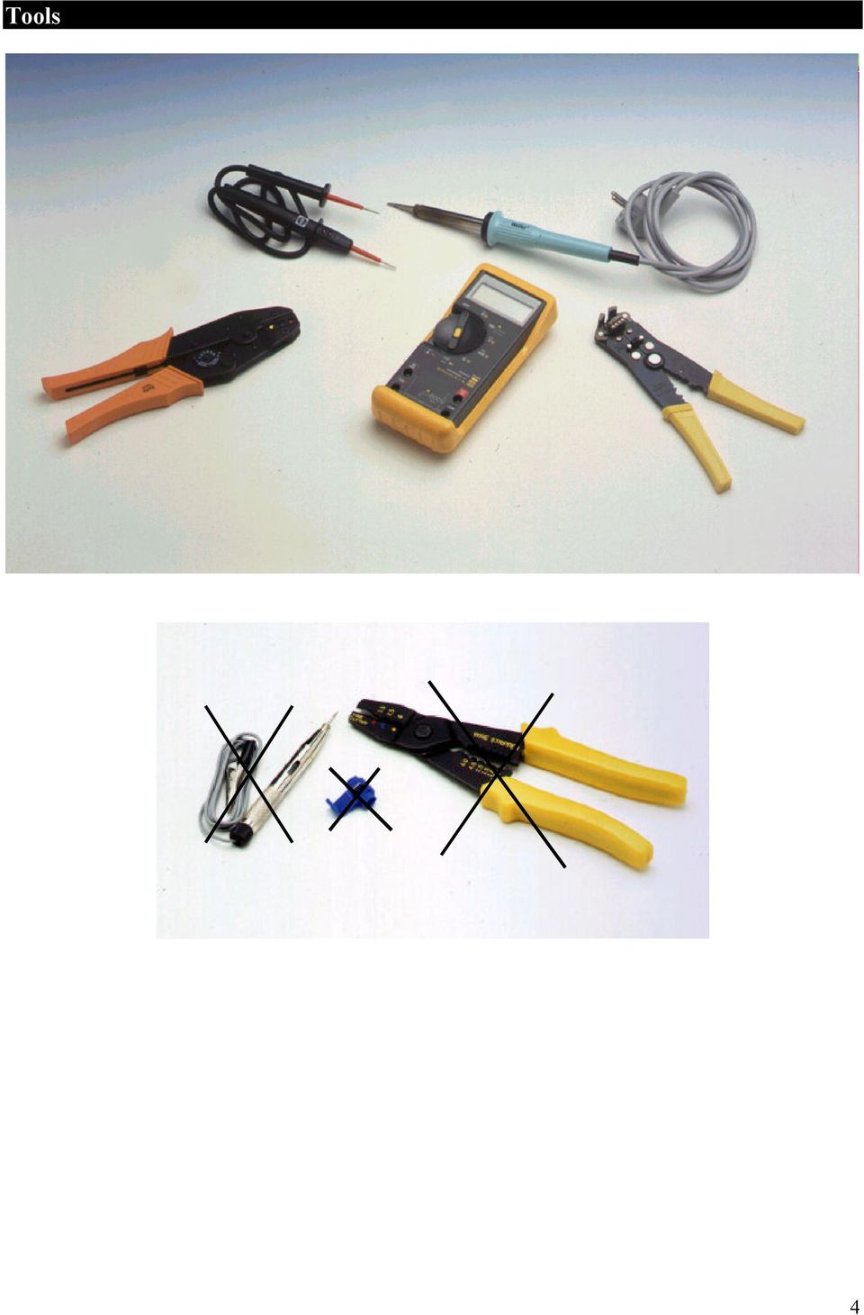
4 Tools 4
5 Contents Wiring diagram Page 3 Instructions for wiring diagram Page 6-8 Preparations for installation Page 9 Positioning of the Alarm Units Page 9-10 Attention! Page 10 User instructions Page Coding new Remote Control Units Page 13 Connection of Central Locking Page Programming of alarm Page Technical data Page 20 Approval Page 20 5

6 Instructions for the wiring diagram --- Further information, see technical manual. P-1 Connection of Central Locking cf. page 6 P-2 Multiplug, Backup Alarm, Immobilizer Module and Pager (auxiliary equipment) This is the connection for auxiliary equipment such as the DEFA Backup Alarm, the DEFA Immobilizer Module or the Pager (Remote Alarm). Cf. separate assembly instructions. P-3.1 Current supply, red lead To be connected to a distributor via a 25A fuse (fuse box). P-3.2 Input, starter kill, red/black lead (only applies to 821X models) Separate control current lead from the ignition lock to the starter (connection 50) near the ignition lock. Connect the lead end coming from the starter with P-3.2 red/black lead. P-3.3 Ground, black lead Connect directly to the vehicle body. Important: lead must not be extended. P-3.4 Output, starter kill, white/green lead (only applies to 821X models) The other lead end (50) leading to the starter is connected to P-3.4 white/green lead. P-4.1 Channel 3 Output for the Remote Control of the electric DEFA Car Heating System. When activated, the output supplies +12V until the function is deactivated again. Maximum load: 350 ma. P-4.2 Channel 2 When activated, the output is grounded until the button is pressed. Use as required. Maximum load: 350 ma. P-4.3 Channel 1 Output for electrical luggage compartment opener. When activated, the output is grounded for 1 second. This functions only when the alarm is switched off. Maximum load: 350 ma. P-4.4 Auxiliary equipment, white/red lead This alarm loop protects integrated auxiliary equipment in the car such as radio/cassette players or similar equipment. The circuit is normally closed (NC) and triggers the alarm when interrupted. P-4.5 6
. P-3.")
7 Door trigger 1, grey lead This input is normally open (NO) triggers the alarm when a contact to ground is made. Connect to the existing door switch circuit of the car. If the car has two separate circuits from the front and rear interior illumination, door trigger 2 (P-4.12) can be used for the rear doors, and input P-4.5 can be used for the front doors. P-4.6 Bonnet trigger, black/grey lead This input is normally open (NO) and triggers the alarm when connected to ground, i.e. when the bonnet is opened. Install DEFA Bonnet Switch. This should be installed in such a position as to make it inaccessible from either the underside or the front of the car. P-4.7 Light output 1, grey/red lead Connected directly to the right turn signal lamp circuit in the car. Maximum load: 7.5 amp. (90 watt). Fused with automatic circuit breaker. P-4.8 Siren Output to Siren. Connect the two Siren leads to P4.8 and P4.9. P-4.9 Siren Output to Siren. Connect the two Siren leads to P4.8 and P4.9. P-4.10 Ignition signal, white/brown lead Connect lead to ignition output of ignition switch. P-4.11 Luggage compartment trigger, white lead Connect to the normal luggage compartment switch if it is switched to ground. If it is switched to positive, a DEFA Polarity Inverter must be used. P-4.12 Door trigger 2, grey/white lead This input is normally open (NO), and triggers the alarm when contacted to ground This is an additional door switch input for NEGATIVE switches and is used particularly when there are separate circuits for the front and rear doors. P-4.13 DEFAnet This output can control DEFA Power Module. P-4.14 Light output 2, grey/black lead Connected directly to the left turn signal lamp circuit in the car. Maximum load: 7.5 amp. (90 watt). Fused with automatic circuit breaker. 7

8 P-5 Plug for auxiliary Sensors Cf. separate assembly instructions. P-6 Plug for Glassbreake Sensor Standard for all models with the letter G in the model designation. If a window is broken, the Glassbreake Microphone triggers the alarm. P-7 Plug for Microwave Sensor Standard for all models with the letter M in the model designation. If the sensor detects motion in the vehicle interior, the alarm is triggered. P-8 Plug for LED Universal LED bracket: The LED can be installed on the instrument panel, on the A-pillar, the windscreen or at any other position desired. Embedded LED bracket: Use an 8.0 mm drill if the bracket is to be embedded in metal plates, a mm drill for plastic material and a 7.0 mm drill for padding material. 8

9 Preparations for installation Further information, see technical manual. The workshop always holds complete responsibility for performing all necessary safety measures on installation of the alarm system. Observe any instructions issued by the car manufacturer. Before making any connections, use a voltmeter/multimeter to check the connection points. Always ensure that the connection points are well insulated by using, for example, shrinkdown plastic tubing or insulation tape. Avoid installing connection points or installation components in the immediate vicinity of airbag modules or other safety systems. The alarm can act on all petrol and diesel cars having a 12V power source. Important: DEFA alarm modules, series 820 (without DEFA Immobilizer), may only be installed in vehicles with approved original Immobilizers; if this is not the case, the Alarm will not be subject to type approval. A list of recognised original start lock systems is available from DEFA or the DEFA representative in your country. Positioning of the Alarm units Central Unit Attach the Central Unit below the instrument panel or at a suitable point in the vehicle interior using plastic fastening strips. The Central Unit should not be visible, and should be as inaccessible as possible. Important: The Central Unit must be installed with its plugs facing downwards to ensure that condensation water cannot run along the cables into the unit. Main fuse The main fuse (25 amp.) should be attached in the vicinity of the current power source. Siren Install in the engine compartment, exposed as little as possible to spray water and heat from exhaust or turbocharger components (minimum distance 30 cm). The Siren aperture must face downwards to prevent water accumulating in it. Important: Never install the Siren with the aperture facing upwards. The Siren must not be accessible from the underside of the car. Important: Never install the Siren with the aperture facing upwards. Glassbreake Sensor The Glassbreake Microphone is installed on the instrument panel or in the centre console. Clean the installation surface with a grease dissolving agent and then fasten the Glassbreake Sensor with the enclosed double-sided adhesive tape. LED Install in instrument panel using the embedded bracket or fasten to the instrument panel/windscreen using a universal bracket or double-sided adhesive tape. The LED must be clearly visible from outside. Microwave Sensor The preferred location is at the centre of the car roof, 40 cm from the windscreen, under the roof lining. If this is not possible, it can be installed in the centre console. The sensor can be installed behind plastic covers but not behind metal covers, as these would block the waves from the sensor. Please note that some cars have a thin metal film in the roof lining. In these cases, the sensor must not be installed behind this lining. 9

10 If the sensor is attached to the inside of the roof, the arrow with the mark UP is usually located on the underside of the sensor and points towards the rear of the car interior. If the sensor is attached to the centre console, the arrow with the mark UP is usually located on the side of the sensor facing the interior. The sensitivity of the sensor must be checked and, if necessary, adjusted after installation. Important: Loose metal objects such as keys, coins, etc., can trigger the alarm if they are too close to the sensor. Antenna feed lead The active (white) part of the antenna must be attached in as free a location as possible, and not in the vicinity of metal or other leads. The position of the antenna is a major influence on its range. Alarm signs (decals) Attach DEFA Auto Security decals to both the front side windows and to the windscreen or rear screen. Important: The decals must not obscure the driver s line of sight. The sticker with details of the alarm model is attached in the glove compartment. The relevant model is checked. Attention! The DEFA Auto Security Alarm Module should be installed in accordance with the manufactorer s instructions. The selection of a good installer is recommended. The national distributor may be contacted to indicate appropriate installers. The installation certificate supplied with the alarm shall be completed by the installer. Making any alterations or additions to the alarm will automatically invalidate the certificate of installation. 10

11 User Instructions Further information, see technical manual. Your DEFA Auto Security Alarm is activated using the two buttons (A and B) on the Remote Control. The two buttons are easy to tell apart, as button A is noticeably higher. Button A Button B «Press» means that you press the button for a maximum of 1 second. «Hold» means that you press the button for at least 2 seconds Alarm ON (arm) Press button A. The turn signal lamps flash once and the alarm siren emits a «click» to confirm that the alarm is ON. The LED illuminates for 20 seconds and then starts to flash, to confirm that the alarm and the Glassbreake/Microwave Sensor are switched ON. Press button A Temporary deactivation of Sensors You can also set the alarm to ON without activating the sensors for motion in the interior or impact against the screen. This can be necessary if, for example, a pet is left in the vehicle. Quickly switch the ignition ON and OFF again. Exit the vehicle and, within 30 seconds, press button A twice briefly (maximum 3 seconds between pressing). The LED starts flashing immediately. The turn signal lamps illuminate for approx. 1 second. The sensors are reactivated when you switch ON the alarm the next time. 11

12 Alarm OFF (disarm) Press button B. The turn signal lamps flash twice to confirm that the alarm is OFF. The LED stops flashing. Press button B If the alarm was triggered during your absence, the turn signal lamps flash five times and the alarm siren emits a «click» five times when the alarm is disarmed. The LED now flashes to indicate which sensor had triggered the alarm. (cf. table page 16). Emergency deactivation If the Remote Control is broken or lost, deactivate the alarm as follows: Your Emergency Code is: DEFA Central Unit 821X P/N:10011 D S/N: PIN-kode: X- X- X- X- X Manufactured by DEFA A.S, Norway DEFA Hotline : Unlock and open the car door. The Alarm is activated! 2. Turn the ignition ON and OFF five times in a row. The Led "flickers". 3. When you turn ON the ignition once again, the Led will blink. Let the Led blink as many times as the first digit of your PIN-kode, and turn OFF the ignition. 4. Turn ON the ignition and repeat the procedure until you have gone through every digit in your PIN-kode. The Alarm is now disarmed. If you make a mistake, start over again at step 3. Start the car immediately! A. Consult your card with the PIN code and locate your five-digit PIN code (Personal Identification Number) B. Follow the instructions on the emergency code card Important: If you make a mistake, you can repeat the procedure from 3. onwards as often as required. Important: Don t forget - keep your PIN Code on your person. Do not leave it in the car! 12

13 Coding of new Remote Control Units Further information, see technical manual. A B C D E F G Press button B to switch the alarm and the Immobilizer (if present) OFF. The emergency deactivation can also be used. Switch the ignition ON and OFF 5 times. The LED flashes rapidly. When you switch the ignition ON again, the LED should flash. Allow the LED to flash as many times as the first number of your PIN code and then switch the ignition OFF again (the LED stops flashing). Switch the ignition ON again and repeat the procedure until all digits of the PIN code have been entered. The LED flashes rapidly. If you make a mistake, start again at «C» with the first digit of the PIN code. Switch the ignition ON again and press buttons A and B of the Remote Control Unit being programmed simultaneously (one Remote Control Unit at a time). Press both buttons until you receive the sound and light confirmation. Switch the ignition OFF once all Remote Control Units have been coded. Important: Coding the keys deletes the old codes, A maximum of 4 Remote Control Units can be coded. Connection of Central Locking Further information, see technical manual. P-1 Multiplug, Central Locking Plug for connection of the Central Locking, cf. diagram, page 14 The plug for the Central Locking P-1 must be configured (assigned) for the relevant car. If the function of the Central Locking is unclear, the original circuit diagrams for the car must be consulted. Always check with a voltmeter/multimeter before making any connections. The leads in the P-1 plug which are not used must be disconnected or insulated. Important: Each relay in the Central Unit can be loaded with a maximum of 15 amps. The Central Unit can become damaged if correctly wired or overloaded. Output P-1.1 is fused by an automatic circuit breaker. P-1 Plug Function Colour P1.1 Battery + Red/white P1.2 Lock NC White/orange P1.3 Ground Black/white P1.4 Unlock COM Yellow P1.5 Lock COM White/blue P1.6 Lock NO White/brown P1.7 Unlock NO Green P1.8 Unlock NC Lilac 13

14 The circuit diagrams below show the usual circuit options. +12V UNLOCK LOCK +12V UNLOCK LOCK 15A GND 15A GND BLUE GREEN To DEFA central lock motor 1 A : LOCK AND UNLOCK 4 +12V UNLOCK LOCK +12V UNLOCK LOCK 15A GND 15A GND B : UNLOCK A : LOCK B : UNLOCK A : LOCK V UNLOCK LÅS +12V UNLOCK LOCK 15A GND 15A GND B : UNLOCK A : LOCK 3 A : LOCK AND UNLOCK 6 14

15 Programming the alarm Further information, see technical manual. The alarm contains a register that allows various functions to be programmed or altered using the Remote Control and the ignition key. Please read the detailed function description on the following pages. Function Description 1 Cause of Alarm trigger 2 Number of Remote Controls 3 Alarm sounds 4 Passive arming 5 The sensitivity of the Microwave Sensor 6 Remote Control with Slider Switch 7 Central locking - time 8 Central locking - security function 9 Starter kill/immobilizer 10 Convenience locking 11 Panic function (Remote triggering of alarm) 12 Production settings 13 Entry of PIN code for Immobilizer Definition of pressing and holding programming buttons on Remote Control : Press means: press for a maximum of 1 second. Hold means: press for at least 2 seconds. Procedure for programming: A) Switch the ignition ON and OFF five times. The LED flashes rapidly. B) Switch the ignition ON again, allow the LED to flash twice and switch the ignition OFF again. Repeat 5 times. After the fifth time, the LED will flash rapidly when the ignition is switched OFF again. C) Switch the ignition ON. Press button A to activate function 1. The function that is active is indicated by the number of sound signals. D) Pressing button A again activates the next function. Hold button A to return to the previous function. E) Once you have reached the desired function, you can program or alter the function as described on pages 16, 17, 18 and 19. F) If you want to program some more functions, press button A. You can then select the function by either pressing or holding button A. G) Once you have completed programming, switch the ignition OFF. 15
 12 Production settings 13 Entry of PIN code for")
16 Function 1: Cause of Alarm trigger Press button A to obtain information about the cause of the alarm last triggered. Press button B for information about the alarm triggered previously. Hold button B to return to the last alarm. Hold buttons A and B simultaneously to delete the trigger cause memory. The Central Unit can store up to 10 alarm events. Alarm triggered by: Number of flashes Auxiliary Sensor 1 2 Open door 3 Open bonnet 4 Open luggage compartment lid 5 Ignition 6 Attempt to remove secured object (stereo, ski box, etc.) 7 Microwave Sensor 8 Glassbreake Sensor 9 Auxiliary Sensor 2 10 Function 2: Number of Remote Control Units Press button B to learn how many Remote Control Units are connected to the alarm. The number of units is indicated by the number of flashes. Function 3: Alarm sounds Press button B to activate the set alarm sound for 5 seconds. Press button B again to select the next alarm sound and hold button B to return to the previous sound. A total of 6 different sounds are available. Function 4: Passive arming Passive arming means that the alarm is switched on 12 seconds after the ignition is switched off and the doors are closed. Press button B to indicate: 1 flash if active arming is selected 2 flashes if active arming is selected regardless of the opened door. 3 flashes if passive arming is selected. Press button B again to select the next function. The number of confirmation sounds indicates the status currently set. Function 5: The sensitivity of the Microwave Sensor For Control purposes the sensitivity level of the detector is indicated by a number (1-8) of short signals in the LED.The lowest level is 1, the highest is 8. Factory setting is 3. Press button B to indicate the valid sensitivity level. Press button B to increases the sensitivity level while holding button B reduces the level. The number of flashes in the LED indicates the level. Selected sensitivity level is confirmed by releasing the detector. Last choosen step will be selected sensitivity level. 16
 7 Microwave Sensor 8 Glassbreake Sensor 9 Auxiliary Sensor 2 10 Function 2: Number of Remote Control Units Press button B to learn how many Remote Control Units are connected to the alarm.")
17 Function 6: Setting of Remote Control with Slider Switch The Remote Control with Slider Switch can be programmed for 3 different modes: Programming Press A Hold A Press B Hold B Position of Slider Switch 1 flash Alarm ON Close windows Alarm OFF Windows open 2 flashes Alarm ON Close sliding roof or Channel 2 Alarm OFF Open sliding roof or Channel 1. (Open luggage compartment) 3 flashes (Standard) Alarm ON Close tilted sliding roof or Channel 3. (Car heating ON) Alarm OFF Tilt sliding roof or Channel 3. (Car heating OFF) Programming 1 provides the functions in line 1 of the table Programming 2 provides the functions in lines 1 and 2 of the table Programming 3 provides the functions in lines 1, 2 and 3 of the table If programming 1 is selected, the middle and top Slider Switch positions can be used to operate the alarms in 2 other cars. If programming 2 is selected, the top Slider Switch position can be used to operate the alarm in one other cars. If only the electric window winders are to be operated, the original Remote Control can be used (1:1). A Remote Control with Slider Switch is not required. A precondition for programming is that the Remote Control has been coded with the Slider Switch in the bottom position. Press button B to indicate the programming of the Slider Switch: 1 signal corresponds to point 1, 2 signals to point 2 and 3 signals to point 3. Press button B again to select the next programming procedure or hold button B to select the preceding programming procedure. The number of confirmation signals indicates the selected programming procedure. 17
 Programming 1 provides the functions in line 1 of the table Programming 2 provides the functions in lines 1 and 2 of the table Programming 3 provides the functions in lines 1, 2 and")
18 Function 7: Time for Central Locking Press button B to indicate the current Central locking pulse factor. 1 flash = 1 second pulse 2 flashes = 4 seconds pulse 3 flashes = 0.5 seconds pulse Press button B again to select the next pulse length, hold button B to select the preceding factor. The number of confirmation signals indicates the selected pulse factor programmed. Function 8: Security functions of Central locking Press button B to indicate the current setting. When this function is selected, it prohibits activation of the alarm until you have exited the vehicle. This function is intended for vehicles with a locking system for the Central Locking. 1 flash = Security function not selected (Standard) 2 flashes = Security function selected Press button B again to select the next function. The number of confirmation signals indicates the current status. Function 9: Start lock/immobilizer Press button B to indicate the current setting. Starter kill: The lock function is switched on at the same time as the alarm is armed and is deactivates as soon as the alarm is switched off again. Immobilizer: This locking function is activated automatically 30 seconds after the ignition is switched off and a door is opened. The Immobilizer is deactivated when you switch off the alarm. If you do not start the car within 30 seconds after opening the doors, the Immobilizer is activated again. 1 flash = Immobilizer is selected (standard on 823) 2 flashes = Starter kill is selected (standard on 821) Press button B again to select the Immobilizer, hold button B to select the start lock. The number of confirmation signals indicates the current status. Function 10: Convenience closing Switching on the alarm can simultaneously lock the doors and close the sliding roof. Press button B to indicate the current setting. 1 flash = Function is not selected (standard) 2 flashes = Convenience closing via the original system 3 flashes = Convenience closing via DEFA Power Module, closes only electric window winders Press button B again to select the next convenience closing mode or hold button B to select the preceding one. The number of confirmation signals indicates which convenience closing mode is selected. Application of function: Hold button A until all elements are closed. Function 11: Panic function 18

19 Press button B to indicate the current setting. 1 flash = Function is not selected 2 flashes = Panic function is active when buttons A and B are held simultaneously (standard) 3 flashes = Panic function is activated for 30 seconds after buttons A and B were held simultaneously. The buttons can be released in the meantime. Press button B again to select the next function. The number of confirmation signals indicates the current status. Function 12: Factory settings The following settings are provided ex works: Function 3: Alarm sound no. 1 Function 4: Active arming Function 6: Programming of all functions (setting 3) Function 7: Activation time of Central Locking; 0.5 seconds Function 8: Security function not selected Function 9: Start lock selected (821). Immobilizer selected (823) Function 10: Convenience closing; OFF Function 11: Panic function, active for as long as A and B buttons are held If the actual settings differ from the factory settings, they can be reset to the above settings by pressing button B. Function 13: Entry of PIN code in Immobilizer Unit If an Immobilizer module is retrofitted or replaced, the PIN code must be entered into the alarm to allow the vehicle to be started. 1. Press button B 2. Switch ignition OFF 3. Switch ignition ON, allow LED to flash the same number of time as the first digit of the Immobilizer PIN code 4. Switch ignition OFF 5. Repeat points 3 and 4 until you have entered all of the digits of your PIN code. When the ignition is switched off for the last time, the LED will flash rapidly. This means that you have completed the coding. 6. If you make a mistake, you will have to restart the procedure from the beginning. 19

20 Technical data Central Unit, 800 series Operating voltage: 9-15 V d.c. Operating temperature: -40 C to +85 C Exterior dimensions: 159 x 80 x 34 mm Power consumption Armed Disarmed 820/821X-G: 13 ma 18 ma 820/821X-M: 19 ma 18 ma 820/821X-MG: 19 ma 18 ma 820/821X-MG Backup 29 ma 35 ma 823X-MG: 19 ma 18 ma Approval The EEC approval mark will be affixed on a label that is placed on the rear side of all the units approved. 20

1R / 4-BUTTON SERIES
 Button 1 1R / 4-BUTTON SERIES VEHICLE SECURITY SYSTEM Standard Features: Two 4-Button Remote Transmitters Status indicator (LED) Valet / override switch Multi-tone siren Dual stage impact detector Remote
INSTALLATION GUIDE. www.security.soundstream.com FCC ID NOTICE
 AL.1 AUTO SECURITY SYSTEM INSTALLATION GUIDE www.security.soundstream.com FCC ID NOTICE This device complies with Part 15 of the FCC rules. Operation is subject to the following conditions: 1. This device
WIRING HARNESS FOR AS635P4. BLUE PLUG RED, BLUE, BLACK, WHITE - Plug in dual stage sensor harness
 WIRING HARNESS FOR AS635P4 ANTENNA NOT USED 5 PIN WHITE PLUG 2 PIN WHITE PLUG GREEN - PARKING BRAKE INPUT (-) BLUE - NOT USED 3 PIN BLUE PLUG RED, BLUE, BLACK, WHITE - Plug in dual stage sensor harness
e-ask electronic Access Security Keyless-entry
 e-ask electronic Access Security Keyless-entry e-fob Keyless-entry entry System Full-Function Function Installation Manual FCC ID: TV2EFOB1 (UM20 ~ 22793-02) Table of Contents Introduction... 1 e-fob Operation
Multi Function, User Configurable Remote Vehicle Security System with 4 Button Replaceable Membrane Remote Transmitter
 MODEL PRO-9744 INSTALLATION MANUAL Multi Function, User Configurable Remote Vehicle Security System with 4 Button Replaceable Membrane Remote Transmitter This System Allows The Transmitter Buttons To Be
How To Control A Car Alarm On A Car With A Remote Control System
 MODEL CA100 REMOTE CONTROL AUTO ALARM SYSTEM INSTALLATION & OPERATION INSTRUCTIONS WIRING DIAGRAM Black Antenna Wire 6 Pin 6 Pin Mini Connector Valet Switch Blue LED Indicator Blue Wire: (-) 200mA Unlock
Button 1 Button 2. Button 3 Button 4. Programmed Remote Transmitter. Button Function Condition
 WWW.STELLAR.COM ST9000 SECURITY SYSTEM Button Function Condition 1 a. Arm and lock doors b. Car finder with sound c. Temporary stop alarm from sounding d. Remote lock doors 1 for 2 sec. Panic Anytime a.
SNIPER X1 VEHICLE SECURITY SYSTEM
 SNIPER X1 VEHICLE SECURITY SYSTEM Installation Manual Table of Contents 1. FEATURES & SPECIFICATIONS... 2 2. TRANSMITTER BUTTONS:... 2 3. FUNCTION... 2 3.1 Key Function:...2 3.2 Remote Transmitter Code
Model AM2. Installation Guide
 Model AM2 Installation Guide NOTE: This product is intended for installation by a professional installer only! Any attempt to install this product by any person other than a trained professional may result
MAGICAR M870AS. Car alarm with two-way remote and remote - start system Installation guide
 MAGICAR M870AS Car alarm with two-way remote and remote - start system Installation guide EN English TABLE OF CONTENTS I. INTRODUCTION...4 II. PLACING...4 III. ADDITIONAL RELAY 12V CONNECTION...1 IV. WIRING
Car Alarm Series 2 B 2 Buttons
 Car Alarm Series 2 B 2 Buttons G22 SE (External - Shock Sensor) Version 3 Software 67 Plus www.geniuscaralarm.com 21 CAR ALARM GENIUS Series 2B 2 Buttons - G22 Se (External Shock Sensor) Module controlled
INSTALLATION MANUAL VEHICLE SECURITY SYSTEM CE-SS200
 INSTALLATION MANUAL VEHICLE SECURITY SYSTEM CE-SS200 FUSION CULTURE TABLE OF CONTENTS There s no point doing something if no one notices. We ve always believed the way to make things happen is by getting
PRO PLM Installation Instructions
 PRO PLM Installation Instructions PROFESSIONAL INSTALLATION STRONGLY RECOMMENDED Installation Precautions: Roll down window to avoid locking keys in vehicle during installation Avoid mounting components
INSTALLATION GUIDE OWNER S GUIDE
 INSTALLATION GUIDE OWNER S GUIDE KEYLESS ENTRY MODELS KE100 / KE150 / 1702 CONTENTS System Features... 1 System Components... 1 Technical Assistance... 1 Before You Begin... 1 Precautions... 1-2 Making
OPERATING INSTRUCTIONS SECURITY SYSTEM KIT NO.: 08E51-EP4-101. 2004 American Honda Motor Co., Inc. - All Rights Reserved. 1
 OPERATING INSTRUCTIONS SECURITY SYSTEM KIT NO.: 8E5-EP4-24 American Honda Motor Co., Inc. - All Rights Reserved. Contents Introduction... 3 Emergency Disarming During Alarming... 4 During the Entry Delay
INSTALLATION MANUAL 3RP / 5RP 4-BUTTON SERIES VEHICLE SECURITY SYSTEMS
 3RP / 5RP 4-BUTTON SERIES VEHICLE SECURITY SYSTEMS INSTALLATION MANUAL Before you begin the installation Read the INSTRUCTIONS! Always use a multi-meter when verifying vehicle wiring. Before mounting the
INSTALLATION GUIDE OWNER S GUIDE
 INSTALLATION GUIDE OWNER S GUIDE SECURITY SYSTEM PRO-SERIES 5002 CONTENTS System Features... 1-2 System Components... 2 Technical Assistance... 2 Before You Begin... 2 Precautions... 2-3 Making Connections...
ODYSSEY. Security System Owner s Manual. Kit No. 08E51-SHJ-100 08E55-SHJ-100. 2004 American Honda Motor Co., Inc. - All Rights Reserved.
 Kit No. 08E5-SHJ-00 08E55-SHJ-00 Security System Owner s Manual ODYSSEY 004 American Honda Motor Co., Inc. - All Rights Reserved. Contents Introduction... 3 Emergency Disarming During the Panic Alarm Activation...
HONDA ACCORD 1985-2005
 HONDA ACCORD 1985-2005 VEHICLE WIRING Copyright 2002-2004 Triple S Customs WIRING INFORMATION: 1985 Honda Accord WIRE WIRE COLOR WIRE LOCATION 12V CONSTANT WHITE or WHITE/BLACK Ignition Harness STARTER
VEHICLE SECURITY SYSTEM G25/G20
 VEHICLE SECURITY SYSTEM G25/G20 Limited Lifetime Warranty This vehicle security system is warranted to the original purchaser, to be free from defects in material and workmanship. The manufacturer will
FALCON WORLD CLASS SECURITY. Advanced Alarm System for Vehicles with CAN-Bus. Installer Manual NATIONWIDE INSTALLATION SERVICE 0800 622 474
 FALCON WORLD CLASS SECURITY FALCON PREDATOR CAN-BUS ALARM Advanced Alarm System for Vehicles with CAN-Bus Installer Manual NATIONWIDE INSTALLATION SERVICE 0800 622 474 HELPLINE: 0906 700 10 20 (All calls
PUSH BUTTON START INSTALLATION MANUAL
 PUSH BUTTON START INSTALLATION MANUAL ALTHOUGH THIS PRODUCT HAS BEEN THOROUGHLY TESTED KPIERSON TECHNOLOGIES ASSUMES NO RESPONSIBILITY FOR ANY DAMAGE THAT MAY RESULT BY THE INSTALLATION OF THIS PRODUCT.
i ChatterBox! Motorcycle Security
 i Before you Start the Installation * Please read this manual to become familiar with the requirements necessary to complete the installation. * Use a high quality multi-meter to test all wires before
TX GSM SMS Auto-dial Alarm System. Installation and User Manual
 TX GSM SMS Auto-dial Alarm System Installation and User Manual Product Features: 1. 16 wireless zones, 3 wired zones alarm system, suitable for small to medium size offices and homes. 2. The system uses
INSTRUCTION MANUAL FOR. Remote Control Car Alarm with Impact Sensor, Mini-Battery Backup Siren & Engine Immobiliser
 INSTRUCTION MANUAL FOR Remote Control Car Alarm with Impact Sensor, Mini-Battery Backup Siren & Engine Immobiliser A.C.N 001 621 610 SYDNEY / AUSTRALIA Build Date: TO ARM/DISARM ALARM The alarm is activated
TOMAHAWK CAR ALARMS. TW-9010 Two Way Car Alarm System
 TOMAHAWK TW-9010 TOMAHAWK CAR ALARMS TW-9010 Two Way Car Alarm System USER MANUAL INSTRUCTIONS FOR INSTALLATION TOMAHAWK TW-9010 1 2 3 4 5 6 7 8 9 10 11 12 13 14 15 16 17 18 19 20 21 22 23 24 25 26 27
INSTALLATION GUIDE OWNER S GUIDE
 INSTALLATION GUIDE OWNER S GUIDE TALKING ALARM MODEL 3001 CONTENTS System Features... 1 Technical Assistance... 1 Wiring Instructions... 2 Installation Instructions... 3 Operating Instructions... 4-5 Technical
4600 CAN/PLIP INSTALLATION MANUAL
 4600 CAN/PLIP INSTALLATION MANUAL Summary 1. KIT CONTENTS...3 2. INTRODUCTION & INSTALLATION METHODOLOGY (how to access to the vehicle specific technical documents, Data Linker tool, Antares software,
REMOTE TRANSMITTER LAYOUT
 Full Featured Keyless Entry System with Optional Starter Defeat and Passive Immobilize Feature SYSTEM MANUA STANDARD FEATURES Some of the system s standard features include: Two 4-button remote transmitters
Security and Remote Start Installation Guide for models: CA 6150 CA 6550
 PROFESSIONAL SERIES Security and Remote Start Installation Guide for models: CA 6150 CA 6550 2009 Audiovox Electronics Corporation. All rights reserved. 1 Table of Contents Before You Begin... 4 Wire Connection
Keys... 2-2 Master, submaster and valet key... 2-2 Key number... 2-2. Door locks... 2-3 Power door locking switches... 2-5
 Doors and locks Keys........................................................................... 2-2 Master, submaster and valet key..................................... 2-2 Key number...............................................................
HAM841K ALARM CONTROL PANEL FOR COMMERCIAL AND RESIDENTIAL SECURITY SYSTEMS
 ALARM CONTROL PANEL FOR COMMERCIAL AND RESIDENTIAL SECURITY SYSTEMS USER MANUAL USER MANUAL ALARM CONTROL PANEL FOR COMMERCIAL AND RESIDENTIAL SECURITY SYSTEMS INTRODUCTION The (HA-841K) is a complete
Vehicle Alarm System With Channel 2 Auxiliary Output Installation Instructions
 Model PRO 9842 Installation Manual Vehicle Alarm System With Channel 2 Auxiliary Output Installation Instructions This Unit Is Intended For Installation In Vehicles With 12 Volt Negative Ground Electrical
How To Set Off An Alarm On A Car With A Car Alarm On It
 AUTO SECURITY SYSTEM USER S OPERATION GUIDE FCC ID NOTICE This device complies with Part 15 of the FCC rules. Operation is subject to the following conditions: 1. This device may not cause harmful interference,
FUNCTIONS FUNCTIONS PROGRAMMABLE THROUGH THE TRANSMITTER DESCRIPTION
 DESCRIPTION The systems 7463 and 7462 are modular systems which consists of an alarm unit and one audible external siren. These alarm systems can be installed on vehicles with 12V battery with negative
SECURITY SYSTEM ADP-CAN
 INSTALLATION INSTRUCTION SECURITY SYSTEM ADP-CAN Introduction Motorcar security system ADP-CAN is for motorcars provided with CAN net. It is for the work with the motorcar factory security systems or remote
2004 Directed Electronics, Inc. Vista, CA N426V 07-04
 350HV Installation Guide NOTE: This product is intended for installation by a professional installer only! Any attempt to install this product by any person other than a trained professional may result
MAGICAR M871A. Car alarm with two-way remote User s guide
 MAGICAR M871A Car alarm with two-way remote User s guide EN MAGICAR M871A Car alarm with two-way remote User s guide TABLE OF CONTENTS Table of contents...2 1. Important notice...4 2. Introduction...4
Alarm Security Kit - NVR
 Alarm Security Kit - NVR EN The alarm configuration menu (see above right screenshot) allows you to configure and change settings for the PIR movement sensors, window/door sensors, remote controls (key
Wireless Home Security Alarm System AM 500
 Wireless Home Security Alarm System AM 500 12 MONTH GUARANTEE Installation & Operating Instructions INTRODUCTION The AM500 is a simple self-contained alarm system. It protects the home by sounding a siren
MODELS 7007 Gorilla Cycle Alarm 7017 Gorilla Cycle Alarm with 2-way pager system 1017 2-way pager system
 MODELS 7007 Gorilla Cycle Alarm 7017 Gorilla Cycle Alarm with 2-way pager system 1017 2-way pager system Remote Control Motorcycle Alarm System Installation & Operation Instructions Sistema de Alarma de
4693-4698 USER MANUAL
 4693-4698 USER MANUAL Summary 1. INTRODUCTION... 4 2. ARMING AND DISARMING THE SYSTEM...4 3. ACTIVE FUNCTIONS (functions description)...5 4. FUNCTIONS PROGRAMMABLE BY A COBRA INSTALLER (functions description)...7
Installation Instructions: Electrical System for Towing Hitch... 3
 ... 3 Installation Instructions: Electrical System for Towing Hitch... 3 321 527 391 103-002 - 51/12 VW Polo A05 RHD Westfalia 321 525 300 143 VW Polo V RHD, 06/09-321 527 300 143 VW Polo V RHD, 06/09-4
Active Speaker System LX523 AUDAC PROFESSIONAL AUDIO EQUIPMENT. Active Speaker System with remote input LX523. User Manual & Installation Guide
 Active Speaker System LX523 AUDAC PROFESSIONAL AUDIO EQUIPMENT Active Speaker System with remote input LX523 User Manual & Installation Guide AUDAC PROFESSIONAL AUDIO EQUIPMENT User Manual & Installation
MODELS 8007 Gorilla Cycle Alarm 8017 Gorilla Cycle Alarm with 2-way pager system 1018 2-way pager system
 MODELS 8007 Gorilla Cycle Alarm 8017 Gorilla Cycle Alarm with 2-way pager system 1018 2-way pager system Remote Control Motorcycle Alarm System Installation & Operation Instructions Sistema de Alarma de
Applied Electronics. Commercial Dimming System UPDATE NOTICE
 REV. A Applied Electronics Commercial Dimming System UPDATE NOTICE This notice is to inform the end user of an additional feature added to this DP12/2400 dimming unit. This unit has been outfitted with
ANTI-THEFT SYSTEM. 1995 Volvo 850 DESCRIPTION & OPERATION BASIC ALARM. 1995-96 ACCESSORIES & EQUIPMENT Volvo Anti-Theft Systems
 ANTI-THEFT SYSTEM 1995 Volvo 850 1995-96 ACCESSORIES & EQUIPMENT Volvo Anti-Theft Systems 850 DESCRIPTION & OPERATION WARNING: Deactivate air bag system before performing any service operation. For 1995
USER MANUAL V5.0 ST100
 GPS Vehicle Tracker USER MANUAL V5.0 ST100 Updated on 15 September 2009-1 - Contents 1 Product Overview 3 2 For Your Safety 3 3 ST100 Parameters 3 4 Getting Started 4 4.1 Hardware and Accessories 4 4.2
Wireless Home Security System Product Manual (Model #80355)
") Wireless Home Security System Product Manual (Model #80355) Installation Instructions During set-up, if no key is pressed for 15 seconds it will come out of the setup mode and you will have to start over.
Wireless Home Security System Product Manual (Model #80355) Installation Instructions During set-up, if no key is pressed for 15 seconds it will come out of the setup mode and you will have to start over.
PK-01. Standalone door control module. SATEL sp. z o.o. ul. Schuberta 79 80-172 Gdańsk POLAND tel. + 48 58 320 94 00
 Standalone door control module PK-01 Firmware version 1.00 pk-01_en 06/12 SATEL sp. z o.o. ul. Schuberta 79 80-172 Gdańsk POLAND tel. + 48 58 320 94 00 [email protected] www.satel.eu WARNINGS Read carefully
288-289 29024V COMPACT ALARM SYSTEMS
 288-289 29024V COMPACT ALARM SYSTEMS The system is manufactured from the highest quality components to ensure a long trouble free operating life. These instructions are intended to familiarise you with
0 Copyright 1997 Subaru of America, Inc.
 0 Copyright 1997 Subaru of America, Inc. All rights reserved. This book may not be reproduced in whole or in part without the express written permission of Subaru of America, Inc. Subaru of America, Inc.
Wireless Alarm system s manual
 MOUNTVIEW TECH AUSTRALIA PTY LTD Wireless Alarm system s manual ADS A180 Series ADS Security 1/11/2011 1. Before You Begin For your safety and the safety of others, and to ensure that you get the most
Quick Installation Guide LCD GSM ALARM SYSTEM LH http://www.usmartbuy.com
 A. Manipulation Specification Quick Installation Guide 1. Arming Arming means all-around guarded when there is no person at home. All detectors are working. Once something triggers any of the detectors,
Transporter Fitting Locations No. 804 / 1
 Page 1 of 10 Transporter Fitting Locations No. 804 / 1 Pin connector assigment of selected connections Overview: 1 - Ignition/starter switch -D- On steering column Connector assigment chapter 2 - Onboard
KEYLESS ENTRY UPGRADE SECURITY SYSTEM for 2004 TOYOTA HIGHLANDER
 KEYLESS ENTRY UPGRADE SECURITY SYSTEM for 2004 TOYOTA HIGHLANDER DEALER SERVICE AND INSTALLATION MANUAL KIT NO. 00016-30915 Contents PARTS LIST... 2 PARTS ILLUSTRATIONS... 2 VEHICLE PREPARATION... 3 INSTALLING
LMU-5000. Hardware and Installation Guide
 LMU-5000 Hardware and Installation Guide Plan The Installation Verify Power, Ground and Ignition. Be sure to check each source (power, ground and ignition) to ensure that the proper signaling exists. This
VEHICLE SECURITY SYSTEM. Car Alarm System With Command Confirmation
 VEHICLE SECURITY SYSTEM Car Alarm System With Command Confirmation About Your System Congratulations on your purchase of this state-of-the-art vehicle security system. With proper installation this system
www.sebury.com.cn Digital Keypad Use s Manual
 K3 K4 www.sebury.com.cn Digital Keypad Use s Manual Contents Introduction Introduction Specifications Intramural Interface Circuit 3 Mounting 3 Wiring 5 Power UP 7 Engineer Programming Mode 7 The K3/K4
INSTALLATION INSTRUCTIONS
 INSTALLATION INSTRUCTIONS Accessory Application Publications No. AII23628 2003 PILOT Issue Date MAY 2002 PARTS LIST Security System Kit (sold separately): P/N 08E51-S84-100 2 Remote controls Attachment
WIRELESS ALARM KIT INSTRUCTION MANUAL COMPLETE ALARM SYSTEM FOR HOME OR BUSINESS. Model Number: IT214054
 WIRELESS ALARM KIT COMPLETE ALARM SYSTEM FOR HOME OR BUSINESS Model Number: IT214054 INSTRUCTION MANUAL Warranty Details/Support This product is warranted against defects for a period of One year if the
SP-100 REMOTE CONTROL ALARM SYSTEM INSTALLATION & OPERATING INSTRUCTIONS INTRODUCTION
 SP-100 REMOTE CONTROL ALARM SYSTEM INSTALLATION & OPERATING INSTRUCTIONS INTRODUCTION CONGRATULATIONS on your choice of a Security Plus Remote Alarm System by Crimestopper Security Products Inc. This booklet
Installation Instructions
 Installation Instructions for EVS II Security and Keyless Entry Systems Note: It is recommended that this installation take place prior to rustproofing. The individual delivering the vehicle should review
MotorCycle Alarm by DEF COM 3 INSTALLATION MANUAL 80 C
 DEF COM 3 INSTALLATI MANUAL MotorCycle Alarm by IMMOBILISER (FAIL SAFE SYSTEM) Positive Logic (the relay switches over when the central unit is disarmed and ignition +15 is present.) Fig.2 Fig.3 SUPPLEMTARY
4625-4627 USER MANUAL
 4625-4627 USER MANUAL Summary 1. INTRODUCTION... 4 2. ARMING AND DISARMING THE SYSTEM WITH THE ORIGINAL VEHICLE REMOTE CONTROL OR WITH THE COBRA REMOTE CONTROL...4 3. ACTIVE FUNCTIONS (functions description)...5
by Myles H. Kitchen M.H. KITCHEN & ASSOCIATES www.auto-electronic.com (2002 X5 4.4 owner) March 2, 2004
 March 2, 2004") INSTALLING THE TEKONSHA PRODIGY ELECTRIC TRAILER BRAKE CONTROL IN THE BMW X5 by Myles H. Kitchen M.H. KITCHEN & ASSOCIATES www.auto-electronic.com (2002 X5 4.4 owner) March 2, 2004 INTRODUCTION The 2000
INSTALLING THE TEKONSHA PRODIGY ELECTRIC TRAILER BRAKE CONTROL IN THE BMW X5 by Myles H. Kitchen M.H. KITCHEN & ASSOCIATES www.auto-electronic.com (2002 X5 4.4 owner) March 2, 2004 INTRODUCTION The 2000
INSTALLATION INSTRUCTIONS
 INSTALLATION INSTRUCTIONS Accessory Application Publications No. AII 26327 2004 S2000 Issue Date OCT 2004 PARTS LIST Security System: P/N 08E51-S84-100 Attachment Kit: P/N 08E55-S2A-101 2 Remote controls
Home Security Alarm System
 Home Security Alarm System User Manual (ALM-S02) Read manual carefully before use. PiSector Inc., USA www.pisector.com Thank you for purchasing this home security alarm system. For your safety and better
TYXIA. *2702178_Rev.1* Installation and User Guide. Wireless receiver. TYXIA RF 642-1 channel
 Installation and User Guide TYXIA Wireless receiver TYXIA RF 642-1 channel DELTA DORE Bonnemain - 35270 COMBOURG - France E-mail : [email protected] Unit compliant with the requirements of directives:
Business/Home GSM Alarm System. Installation and User Manual
 Business/Home GSM Alarm System Installation and User Manual Brief Introduction: GSM 900/1800/1900 bands, can be used in most parts of the world Full duplex communication with the host Monitor the scene
Networkfleet 3500 Product Line Installation Guide
 Networkfleet 3500 Product Line Installation Guide Light/Medium Duty (L3500) Heavy Duty (H3500) Universal (U3500) www.networkcar.com/fleet Customer Care: (866) 227-7323 [email protected] Table
PROFESSIONAL HOME ALARM SYSTEM. Important! Please read these instructions carefully.
 WIRELESS AUTODIAL HOME ALARM SYSTEM AM2000 Instructions for use Important! Please read these instructions carefully. IMPORTANT 1 IDENTIFICATION PLEASE CONTACT BEFORE RETURNING THIS PRODUCT TO THE RETAILER
UPGRADE ALARM USER INSTRUCTIONS
 UPGRADE ALARM USER INSTRUCTIONS CYCL PS SECURITY SYSTEMS PROUDLY AUSTRALIAN Proudly designed and engineered in Australia by Dynamco Pty Ltd. Your emergency override PIN is Keep this number in a safe place
The Child Reminder System Installation Manual
 The Child Reminder System Installation Manual Revised June, 2006 Detailed installation information can be found at www.childreminder.com. Get through your installation quickly and easily by calling 1-888-330-6786
2003/2004/2005 TOYOTA COROLLA
 2003/2004/2005 TOYOTA COROLLA KEYLESS ENTRY UPGRADE SECURITY SYSTEM INSTALLATION INSTRUCTIONS KIT NO. 00016-30120 SPECIAL NOTE: Installation Sequences After TMS and Safety mandated preparatory steps have
SVC400P/SVC800P. 4/8 Camera Live Tracking Vehicle DVR Installation Manual. Version 1.0
 SVC400P/SVC800P 4/8 Camera Live Tracking Vehicle DVR Installation Manual Version 1.0 1. MAIN FEATURES... 2 2. PRODUCT OVERVIEW... 2 3. DIMENSIONS... 4 4. PACKAGE CONTENTS... 5 5. MOUNTING AND ENVORNMENTAL
535T Window Automation System
 535T Window Automation System Installation Guide NOTE: This product is intended for installation by a professional installer only! Any attempt to install this product by any person other than a trained
INSTALLATION INSTRUCTIONS
 Rear Vision System Tailgate Handle Camera Mirror Display 2004-2014 Ford F-150 and 2008-2015 Ford Super Duty (Kit part numbers 9002-9521) Kit Contents: Mirror Tailgate Handle with camera and harness Interior
Air conditioning, electrical testing
 just a test. Air conditioning, electrical testing 01-253 Wire and component test using VAG1598 A test box Special tools and equipment VAG 1598 A test box and VAG 1598/11 adapter cable and VAG 1598/12 VAG1526
AUTODIALLER / QUICKDIALLER - SA132
 AUTODIALLER / QUICKDIALLER - SA132 INSTRUCTION LEAFLET ENGLISH www.thermomax-group.com CONTENTS 1 SETUP AT A GLANCE... 2 2 FOREWORD....... 3 3 INSTALLATION...... 4 4 KEYPAD AND INDICATORS...... 5 SETTING
CMD-10k COMMANDER SERIES REMOTE CONTROL ENTRY SYSTEM
 CMD-10k COMMANDER SERIES REMOTE CONTROL ENTRY SYSTEM INTRODUCTION Thank you for purchasing the CMD-10k Commander from Dakota Digital. This, along with many other products that Dakota Digital has to offer,
How To Power A Power Control On An Ip40 (Ipl) With A Power Supply (Iplug) With An Ip20 Controller (Iphones) With Power Control (Power Control) With No Antenna) With The Ip20 (Power)
 With A Power Supply (Iplug) With An Ip20 Controller (Iphones) With Power Control (Power Control) With No Antenna) With The Ip20 (Power)") MODEL NUMBER: ISC910-1-0-GB-XX ISC911-5-0-GB-XX IXP20 CONTROLLER SPECIFICATIONS Working Environment Plastic Housing... Power ImproX IXP20 Controller INSTALLATION MANUAL Designed to work in an indoor (dry)
MODEL NUMBER: ISC910-1-0-GB-XX ISC911-5-0-GB-XX IXP20 CONTROLLER SPECIFICATIONS Working Environment Plastic Housing... Power ImproX IXP20 Controller INSTALLATION MANUAL Designed to work in an indoor (dry)
Fitting/Installation Guide - UNIVERSAL
 ATTENTION: This wiring information is being provided free of charge and on an as is basis, without any representation or warranty. It is your responsibility to verify any circuit before interfacing with
AM/8510 NL GB - Compact motorbike security system
 AM/8510 NL GB - Compact motorbike security system Features and operation Arming To arm the system, press the push-button n. 1 of the radio transmitter once. Arming will be confirmed by: A long flash of
GSM Home Alarm System User Manual. http://www.usmartbuy.com
 GSM Home Alarm System User Manual http://www.usmartbuy.com 1 1. Factory default Normally, all sensors in the big box have been coded (learnt) to the control host Operation Password: 0000 Long-Distance
Business/Home. GSM Alarm system
 Business/Home GSM Alarm system Installation and Users guide Profile For a better understanding of this product, please read this user manual thoroughly before using it. I. General information: GSM 900/1800/1900
Remote Engine Start System User s Information Manual
 Remote Engine Start System User s Information Manual A Few Words About Safety Your safety, and the safety of others, is very important. Operating this Remote Engine Starter System safely is an important
AL-1650-EDPB AL-1750-EDPB AL-1850-EDPB AL-1950-EDPB AL-2050-EDPB
 AL-1650-EDPB AL-1750-EDPB AL-1850-EDPB AL-1950-EDPB AL-2050-EDPB Deluxe Security & Remote Start System Installation Guide July 11, 2012 Temporary cover. Color cover is in a separate file. Installation
Business/Home GSM. Alarm System(III) Installation and Users guide
 Installation and Users guide") Business/Home GSM Alarm System(III) Installation and Users guide I. General information: GSM 900/1800/1900 bands, can be used all over the world. Full duplex communication with the base. Monitor environment
Business/Home GSM Alarm System(III) Installation and Users guide I. General information: GSM 900/1800/1900 bands, can be used all over the world. Full duplex communication with the base. Monitor environment
Business/ Home GSM Alarm System
 Business/ Home GSM Alarm System BUSINESS/HOME GSM ALARM SYSTEM POWER STATUS RECORD SIGNAL User Manual Profile For a better understanding of this product, please read this user manual thoroughly before
CMD-9000 COMMANDER SERIES REMOTE CONTROL ENTRY SYSTEM
 CMD-9000 COMMANDER SERIES REMOTE CONTROL ENTRY SYSTEM INTRODUCTION Thank you for purchasing the CMD-9000 Commander from Dakota Digital. This, along with many other products that Dakota Digital has to offer,
Installation Instructions. ThermoCall TC4. Entry/Advanced
 Installation Instructions ThermoCall TC4 Entry/Advanced Thermo Call TC4 1 2 # 24990A 965 082 AMP 3 4 # 98393A # 67769A Thermo Call TC4 5 ThermoCall TC4 Entry 1 2 3 4 5 6 7 8 9 10 11 12 sw Please refer
Installation Instructions. Thermo Call TC3
 Installation Instructions Thermo Call TC3 1 2 # 24990A 965 082 AMP 3 4 # 98393A # 67769A sw Improper installation or repair of Webasto heating and cooling systems can cause fire or the leakage of deadly
Vehicle Security System VSS3 - Alarm system remote. System Setting Guide - English
 Vehicle Security System VSS3 - Alarm system remote System Setting Guide - English Dear Customer, In this guide you will find the information and operations necessary in order to activate and deactivate
Installation Instructions: Electrical System for Towing Hitch...3
 Fehler! Textmarke nicht definiert....3 Installation Instructions:...3 317 056 391 104-002 - 22/07 Westfalia Skoda 317 056 300 153 Skoda Octavia II (1Z), 4x4, RS, RHD 3 2 1 1 2 3 4 5 6 7 2 317 056 391 104-002
DC-8706K Auto Dial Alarm System
 DC-8706K Auto Dial Alarm System User Guide Basic Contents: 1x the host unit; 1x wireless door (window) magnet; 1x wireless infrared detector; 2x remote control; 1x siren; 1x phone core; 1x AC to DC power
GSM AD05 Slave GSM Auto Dialer- Instruction Manual
 GSM AD05 Slave GSM Auto Dialer- Instruction Manual Please read these instructions before you start the installation Features LCD display Programmable 9 x 32 digit phone numbers for each trigger. 10 second
Automatic Telephone Dialer TD-101(W)
") Automatic Telephone Dialer TD-101(W) The TD-101 is an automatic dialing device which can transmit prerecorded information via the telephone line. The dialer can send two different 10 second voice messages
Automatic Telephone Dialer TD-101(W) The TD-101 is an automatic dialing device which can transmit prerecorded information via the telephone line. The dialer can send two different 10 second voice messages
HWS100 Wireless Home Security System
 4902000 HWS100 Wireless Home Security System Owner s Manual WARNING: Security system devices cannot compensate for loss of life or property. Company is not responsible for any loss or intrusion. CONTENTS
VEHICLE SECURITY SYSTEM Optional Remote Start Module and 2-way Transmitter Instructions Included
 VEHICLE SECURITY SYSTEM Optional Remote Start Module and 2-way Transmitter Instructions Included STANDARD FEATURES Some of the system s standard features include: 4-button remote transmitter LED Status