WEB log. Device connection plans
|
|
|
- Avis Pearson
- 9 years ago
- Views:
Transcription
1 WEB log LIGHT+ 20 BASIC 100 PRO unlimited Device connection plans Version *

2 Copyright Copyright for this manual remains with the manufacturer. No part of this manual may be reproduced or edited, duplicated or distributed using electronic systems, without written permission. Compensation shall be payable in the event of any copyright infringements. All brand names mentioned in this manual are the property of their respective manufacturers and are hereby acknowledged. Details regarding the manual The original document is written in German. All other language versions are translations of the original document and are hereby identified as such. All information in this operating manual has been compiled and checked with the greatest care and diligence. Nevertheless, the possibility of errors cannot be entirely excluded. The manufacturer therefore cannot accept any liability for errors or their consequences. Subject to technical alterations. *Current version The latest version of this document "Device connection plans" can be found on the manufacturer's website.

3 Contents 1. Notes on this operating manual Safety instructions for operation Intended use Personnel Overview of interfaces Cabling RS485 and RS232/ Sensors Irradiance sensors Pyranometer Temperature sensors Hygro-thermal sensors Wind speed sensors Wind direction sensors Weather stations Power quality analyzers Janitza power quality analyzers Energy meter Three-phase energy meter String measuring technology meteocontrol string measuring technology

4 1. Notes on this operating manual This manual is a key aid when it comes to ensuring proper operation of the device. It contains important information and safety notes to help you use the devices correctly, economically and in the intended manner. The manual helps to avoid dangers, to reduce repair costs and downtimes, and to increase the reliability and operating life of the devices. During installation, all the manuals for system modules and components must be taken into account. 2. Safety instructions for operation 2.1 Intended use Only the permitted signals and signal strengths may be applied to the connections of the data loggers and modules used here. Installation is only permitted indoors. For installation outdoors or in a dusty environment, the device must be installed in a standardized protective enclosure. 2.2 Personnel Installation, commissioning and maintenance of the device may only be performed by a qualified electrician. Given their specialist training, knowledge, experience and familiarity with the relevant standards and regulations, a qualified electrician is in a position not only to carry out work on electrical systems but also to recognize and avoid possible dangers unaided. The qualified electrician must comply with the occupational health and safety laws in force. Please note in particular: all national installation and set-up regulations (e.g. VDE in Germany), all generally accepted codes of practice, information on transport, installation, operation, service, maintenance and disposal given in the documentation for the devices used, specific values, limits and information relating to operating and ambient conditions on type plates and in data sheets. 2 48

5 3. Overview of interfaces Overview of interfaces (1) Analog inputs (DI1 DI4) (7) Ethernet (2) Reset button (8) RS485 (3) Digital inputs (DI1 DI4) (9) RS232/422 (4) Power supply (10) Digital output (DO1) (110 V 230 V AC) (5) RJ45 phone socket (PSTN) (11) Switch between RS232 / RS422 (6) Power supply (24 V DC) Can also be operated as RS485 for additional Modbus devices 3 48
 Power supply (24 V DC) Can also be operated as RS485 for additional Modbus")
6 4. Cabling 4.1 RS485 and RS232/422 The two RS485 and RS232/422 interfaces are used to query information recorded on various bus devices such as inverters, power quality analyzers, etc. The RS232/422 interface can also be used as an RS485 interface. In order to do this the interface has to be operated in RS422 mode (for this, please refer to the manual of your WEB log data logger). Which interface you should use to connect inverters and accessories depends on your specific driver. Please refer to the appropriate driver datasheet ( Please note the following regarding the bus cabling: All devices on a bus must use the same protocol to communicate. The data logger functions exclusively as a master on the bus. The maximum permitted number of bus devices has to be observed (see driver datasheets). The order of the bus devices on the bus is unimportant. The use of a repeater is necessary for every 32nd bus device and for long cable runs. The bus should be cabled with a twisted and shielded pair of wires. The shield of the bus cable must be grounded at one end of the connection only. The data logger does not have its own grounding When you wire the bus wires, make sure that AC and DC cables are routed separately. Do not switch the buses signal wires. Different manufacturers interpret the RS485 interface s underlying standard differently. A and B wire labels may be different for different manufacturers. The + and indicators, on the other hand, are unambiguous. To prevent reflections, the bus must always be terminated with a parallel terminator. 4 48

7 Daisy chain If you want to connect more than one device to the bus, you must daisychain the connection. This means that different devices can only be queried jointly if they use the same communication protocol and the same serial communication parameters (baud rate, data bits, parity, stop bits). The first and last device on the bus must be terminated with a resistor. The data logger is provided with integrated terminating resistors that are permanently activated. Daisy chain cabling RS485/

8 Star wiring Another possible way of operating multiple devices on the RS485 bus is called star wiring. In this wiring variant, a HUB 6 Port RS485 S (item number ) is used to seperate the bus into a serveral bus strings. To connect the HUB 6 Port RS485 S to the WEB log, please use a Connect Universal RS cable (item number: ). Various devices can only be queried together if they communicate with the same protocol and have identical serial communication parameters (baud rate, number of data bits, parity, stop bits). Each bus string can have a maximum length of 1200 m. All the devices on the same bus string are wired together in a daisy chain. The first and last device of each bus string must be terminated with a resistor. The HUB has integrated terminating resistors at each interface, which are permanently activated. In this wiring variant, the total number of bus devices may not exceed the maximum permissible number of bus devices. Star wiring for RS

9 7 48

10 5. Sensors 5.1 Irradiance sensors SI-12-TC, SI-12-TC-T Item Product name Item number Particularity Irradiance sensor Si-12-TC Connection cable: 3 m Irradiance sensor Si-12-TC Connection cable: 30 m Irradiance sensor Si-12-TC Connection cable: 15 m Irradiance sensor Si-12-TC Connection cable: 60 m Irradiance sensor Si-12-TC-T Connection cable: 3 m Irradiance sensor Si-12-TC-T Connection cable: 30 m Irradiance sensor Si-12-TC-T Connection cable: 15 m Connection Wire color Use Black Ground Red Power supply (12 24 V DC) Brown Temperature signal (0 10 V / 0 20 ma / ma) Orange Irradiance signal (0 10 V) Configuration data SI-12-TC-T Sensor Measurement Input Unit Gradient Offset Irradiance Analog 0 10 V W/m Temperature Analog 0 10 V C In the case of the sensor SI-12-TC, the brown wire for temperature measurement is not used 8 48
 Brown Temperature signal (0 10 V / 0 20 ma / 12.")
11 Sensor connection 9 48

12 SI-12-TC-LC Connection Wire color Use Black Ground Red Power supply (12 24 V DC) Orange Irradiance signal (0 10 V) Configuration data Sensor Measurement Input Unit Gradient Offset SI-12-TC-T Irradiance Analog 0 10 V W/m

13 Sensor connection 11 48

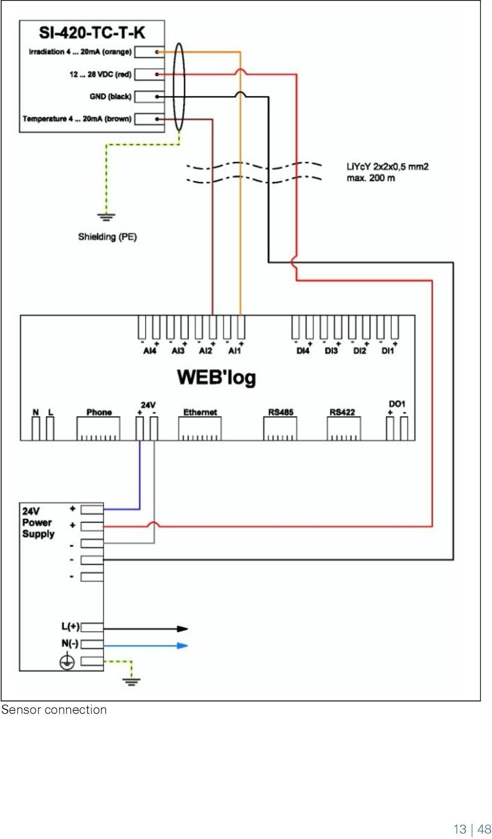
14 SI-420-TC, SI-420-TC-T Item Product name Item number Particularity Irradiance sensor Si-420-TC Connection cable: 3 m Irradiance sensor Si-420-TC-T Connection cable: 3 m Irradiance sensor Si-420-TC-T Connection cable: 15 m Connection Wire color Black Red Brown Orange Use Ground Power supply (12 24 V DC) Temperature signal ( ma) Irradiance signal (4 20 ma) Configuration data Sensor Measurement Input Unit Gradient Offset Irradiance Analog 4 20 ma W/m SI-420-TC-T Temperature Analog ma C In the case of the sensor SI-420-TC, the brown wire for temperature measurement is not used 12 48
 Irradiance signal (4 20 ma) Configuration data Sensor Measurement Input Unit Gradient Offset Irradiance Analog 4 20 ma W/m 2 75-300 SI-420-TC-T")
15 Sensor connection 13 48
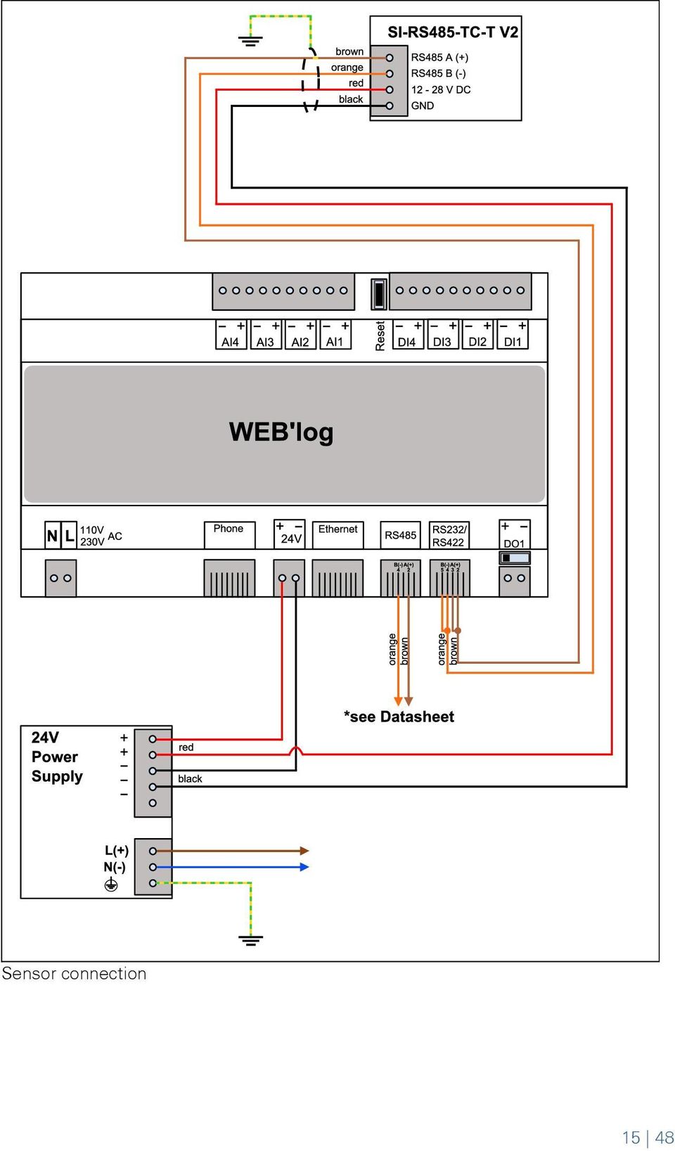
16 Si-RS485-TC-T (Modbus RTU), Si-RS485-TC-T V2 (Modbus RTU) Item Product name Item number Particularity Irradiance sensor Si-RS485-TC-T V Connection cable: 3 m Connection Wire color Use Black Ground Red Power supply (12 24 V DC) Brown RS485 Modbus interface A (+) Orange RS485 Modbus interface B (-) Set the bus address on the sensor (see sensor documentation). If the device is the last one on the RS485 bus, terminate the bus with a 120 Ω terminating resistor. Various Modbus devices can only be queried together if the serial communication parameters are identical (baud rate, number of data bits, parity, stop bits)

17 Sensor connection 15 48
18 5.2 Pyranometer Kipp & Zonen SMP10 / SMP11 (analog interface) Item Product name Item number Pyranometer SMP Connection Wire color Black White Brown Green Use Ground Power supply (5 30 V DC) Irradiance signal GND Irradiance signal (4 20 ma) Configuration data Measurement Input Unit Gradient Offset Irradiance on horizontal plane Analog 4 20 ma W/m Irradiance on module plane Analog 4 20 ma W/m The sensor outputs (power signal) must have a resistance of approx. 500 Ω for a correct measurement. Since the data logger has an internal load resistance of 70 Ω, we recommend you to install a commonly available 430 Ω load resistor on the sensor output. Pyranometers can be used to measure irradiance either on the horizontal plane or on the module plane

19 Sensor connection 17 48

20 Kipp & Zonen SMP10 / SMP11 (Modbus RTU) Item Product name Item number Pyranometer SMP Connection Wire color Use Black Ground White Power supply (5 30 V DC) Gray RS485 Modbus interface B (-) Yellow RS485 Modbus interface A (+) Blue RS485 Modbus interface GND Set the bus address on the sensor (see sensor documentation). If the device is the last one on the RS485 bus, terminate the bus with a 120 Ω terminating resistor. Various Modbus devices can only be queried together if the serial communication parameters are identical (baud rate, number of data bits, parity, stop bits). Pyranometers can be used to measure irradiance either on the horizontal plane or on the module plane
.")
21 Sensor connection 19 48
22 Kipp & Zonen CMP11 with AMPBOX Item Product name Item number Pyranometer CMP AMPBOX Connection Wire color White Green Use Power supply + 24 V DC Analog output 4 ma to 20 ma Configuration data Measurement Input Unit Gradient Offset Irradiance on horizontal plane Analog 4 20 ma W/m Irradiance on module plane Analog 4 20 ma W/m Pyranometers can be used to measure irradiance either on the horizontal plane or on the module plane. The input and output of the AMPBOX are galvanically isolated to prevent feedback and interference and to protect the data logger. The connecting cable between the AMPBOX and the pyranometer must not be lengthened or shortened. Because the AMPBOX and the pyranometer are calibrated together, both devices must always be installed together
23 Sensor connection 21 48
24 5.3 Temperature sensors PT1000 Adhesive Sensor Item Product name Item number PT1000 adhesive sensor Connection Wire color Brown White Use Ground PT1000 temperature signal Configuration data Measurement Input Unit Gradient Offset Temperature PT1000 C
25 Sensor connection 23 48
26 PT100 adhesive sensor with signal converter Item Product name Item number Particularity PT100 adhesive sensor PT100 signal converter 24 V DC Power supply: 24 V DC PT100 signal converter 230 V DC Power supply: 230 V AC Connection Wire color Red White Use Ground Temperature signal PT100 Configuration data Measurement Input Unit Gradient Offset Temperature Analog 0 10 V C The following signal converters are available for connecting the temperature sensor: PT100 Signal converter 24 V power supply PT100 Signal converter 230 V power supply 24 48
27 Sensor connection 25 48
28 5.4 Hygro-thermal sensors meteocontrol compact hygro-thermal sensor Item Product name Hygro- thermal sensor meteocontrol compact Item number Connection Wire color Yellow Black Green Brown Use Power supply for humidity sensor (24 V DC) Power supply for temperature sensor (24 V DC) Temperature signal (4 20 ma) Ambient humidity signal (4 20 ma) Configuration data Measurement Input Unit Gradient Offset Temperature Analog 4 20 ma C Relative humidity Analog 4 20 ma % r. h The sensor outputs (power signal) must have a resistance of approx. 500 Ω for a correct measurement. Since the data logger has an internal load resistance of 70 Ω, we recommend you to install commonly available 430 Ω load resistors on the sensor outputs
29 Sensor connection 27 48
30 5.5 Wind speed sensors meteocontrol compact wind speed sensor (0 10 V) / (4 20 ma) Item Product name Item number Particularity Wind speed sensor meteocontrol Output: 4 20 ma compact Wind speed sensor meteocontrol compact Output: 0 10 V Connection Wire color Use Yellow Wind speed signal ground Green Wind speed signal (4 20 ma) Gray Power supply for heater (24 V AC or DC +) Pink Heater GND (24 V DC -) White Power supply for sensor (24 V AC or DC +) Brown Sensor GND (24 V AC or DC -) Configuration data Sensor Measurement Input Unit Gradient Offset mc comp. wind speed sensor (0-10 V) Wind speed Analog 0 10 V m/s 5 0 mc comp. wind speed sensor (4-20 ma) Wind speed Analog 4 20 ma m/s
31 Sensor connection 29 48
32 5.6 Wind direction sensors meteocontrol compact wind direction sensor (0 10 V) / (4 20 ma) Item Product name Item number Particularity Wind direction sensor meteocontrol Output: 4 20 ma compact Wind direction sensor meteocontrol compact Output: 0 10 V Connection Wire color Use Yellow Wind direction signal GND Green Wind direction signal (4 20 ma) Gray Power supply for heater (24 V AC or DC +) Pink Heater GND (24 V DC -) White Power supply for sensor (24 V AC or DC +) Brown Sensor GND (24 V AC or DC -) Configuration data Sensor Measurement Input Unit Gradient Offset mc compact wind direction (0-10 V) Wind direction Analog 0 10 V 36 0 mc compact wind direction (4-20 ma) Wind direction Analog 4 20 ma
33 Sensor connection 31 48
34 5.7 Weather stations Compact weather station WS501 / WS510 / WS600 UMB (Modbus RTU) Item Product name Item number Compact weather station WS501 UMB Compact weather station WS510 UMB Compact weather station WS600 UMB Connection Wire color Use Green RS485 bus wire A (+) Yellow RS485 bus wire B (-) Brown Power supply for sensor (+24 V DC) White Sensor GND (-) Red Power supply for heater (+24 V DC) Blue Heater GND (-) Set the bus address on the compact weather station (see compact weather station documentation). If the device is the last one on the RS485 bus, terminate the bus with a 120 Ω terminating resistor. Various Modbus devices can only be queried together if the serial communication parameters are identical (baud rate, number of data bits, parity, stop bits)
35 Sensor connection 33 48
36 6. Power quality analyzers 6.1 Janitza power quality analyzers UMG604 (Modbus RTU) Item Product name Item number Particularity Power quality analyzer UMG Power supply: 230 V AC Power quality analyzer UMG Power supply: 24 V DC Set the bus address on the power quality analyzer (see power quality analyzer documentation). If the device is the last one on the RS485 bus, terminate the bus with a 120 Ω terminating resistor. To ensure sufficient query speed for the power control, it is recommended to operate the power quality analyzer as a single device on the bus
37 Sensor connection 35 48
38 7. Energy meter 7.1 Three-phase energy meter ALE3 (Modbus RTU) energy meter Item Product name Item number Energy meter ALE Set the bus address on the energy meter (see energy meter documentation). If the device is the last one on the RS485 bus, terminate the bus with a 120 Ω terminating resistor. Energy meter suitable for IPL function 36 48
39 Sensor connection 37 48
40 Energy meter ALE3 (S0) Item Product name Item number Energy meter ALE Pulse value of the S0 interface is 1000 pul/kwh Energy meter suitable for IPL function Configuring the IPL meter In the factory, the meter s S0 interface is set up in a way that allows for pulses to be transmitted in both directions (in and out), when energy is flowing. With this setting it is not possible to determine the direction of flow. To use the meter for IPL you will need to configure the S0 interface for one energy flow direction. You will need to make the following settings, depending on the recorded measurement. Measurement Use Setting Energy fed into the grid Feed-in meter Out mode Energy drawn from the grid Import meter In mode Energy used by electrical equipment Consumption meter In mode 38 48
41 Sensor connection 39 48
42 8. String measuring technology 8.1 meteocontrol string measuring technology i catcher 8-1B, i catcher 16-1B, i catcher 24-1B (Modbus RTU) Item Product name Item number i catcher 8-1B i catcher 16-1B i catcher 24-1B Set the bus address on the i'catcher (see i'catcher documentation). If this is the last bus device on the RS485 bus, set the terminating switches (Term.) to On. Various Modbus devices can only be queried together if the serial communication parameters are identical (baud rate, number of data bits, parity, stop bits)
43 (1) RJ12 connector (WEB'log), (5) Last i catcher RS485/RS422 (2) Pinout of Connect Universal RS (6) Terminating resistor 120 Ω (3) Terminals (i catcher) (7) Bus cable (4) First i catcher 41 48
44 Connection i catcher, central power supply, separate shield Connection i catcher, central power supply, connected shield 42 48
45 Connection i catcher, decentralized power supply, separate shield Connection i catcher decentralized power supply, connected shield 43 48
46 String Monitoring Units SMU 0825, SMU 1225, SMU 1625, SMU 2422 (Modbus RTU) Item Product name Item number String Monitoring Unit String Monitoring Unit String Monitoring Unit String Monitoring Unit Set the bus address on the String Monitoring Unit (see String Monitoring Unit documentation) If the device is the last one on the RS485 bus, terminate the bus with a 120 Ω terminating resistor. Various Modbus devices can only be queried together if the serial communication parameters are identical (baud rate, number of data bits, parity, stop bits)
47 Sensor connection 45 48
48 46 48
49 47 48
50 48 48
51
52 Text and illustrations represent state-of-the-art technology at the time of printing Subject to technical modifications We assume no liability for printing errors. Version
WEB log. Device connection plans
 WEB log LIGHT+ 20 BASIC 100 PRO unlimited Device connection plans Version 20151210* Copyright Copyright for this manual remains with the manufacturer. No part of this manual may be reproduced or edited,
* DISCLAIMER: Contents. How to Use This Guide: COMMERCIAL INSTALL GUIDE 2
 COMMERCIAL INSTALL GUIDE 2 Contents How to Use This Guide: The first section of this guide is designed to assist you with the installation of your DECK Monitoring hardware. The revenue grade meter and
SmartLogger1000. Quick Installation Guide. Issue 05. Date 2013-12-15 HUAWEI TECHNOLOGIES CO., LTD.
 Issue 05 Date 2013-12-15 HUAWEI TECHNOLOGIES CO., LTD. 2013. All rights reserved. No part of this document may be reproduced or transmitted in any form or by any means without prior written consent of
NC-12 Modbus Application
 NC-12 Modbus Application NC-12 1 Table of Contents 1 Table of Contents... 2 2 Glossary... 3 SCADA...3 3 NC-12 Modbus in general... 3 4 Entire system... 4 4.1 PFC to PC connection alternatives...4 4.1.1
Application/Connection Examples
 This Quick Start Guide is designed to familiarize the user with the connection and configuration of the DTS-305 DIN rail mounted single / 3 phase power & energy meter with RS-485 or TCP communications.
Technical Information POWER PLANT CONTROLLER
 Technical Information POWER PLANT CONTROLLER Content The Power Plant Controller offers intelligent and flexible solutions for the control of all PV power plants in the megawatt range. It is suitable for
WEATHER STATION FOR SOLAR FARM MONITORING
 WEATHER STATION FOR SOLAR FARM MONITORING SOLAR FARM MONITORING SYSTEM: Measures global, horizontal, & background irradiance. Measures wind speed, wind direction, ambient temperature, and relative humidity.
User Manual Revision 2.003 English
 Document code: MN67120_ENG Revision 2.003 Page 1 of 15 User Manual Revision 2.003 English RS232 / RS485 / Ethernet - Converter (Order Code: HD67120) for Website information: www.adfweb.com?product=hd67120
PCS0100en 02.2008. Persy Control Services B.V. Netherlands
 P-Bus Gateway PBGW2.128 Universal gateway between the P-bus protocol and open standard protocols. The variety of available electrical interfaces on the gateway offers a wide range of possibilities for
Technical data. General specifications. Indicators/operating means. Electrical specifications Operating voltage U B Power consumption P 0 Interface
 Release date: 06-0- 09: Date of issue: 06-0- 009_eng.xml Model Number Single head system Features Parameterization interface for the application-specific adjustment of the sensor setting via the service
WxGoos-1 Climate Monitor Installation Instructions Page 1. Connections. Setting an IP Address
 Instructions Page 1 Connections The WxGoos-1 is a self-contained web server and requires 6vdc of power at 300ma. A center-positive 2.1 mm plug is used. There are five ports: 1. 10/100 Ethernet RJ-45 receptacle
Temp-485-Pt100. A temperature sensor (Pt100 or Pt1000) communicating over the RS-485 bus with a simple communication protocol
 communicating over the RS-485 bus with a simple communication protocol") Temp-485-Pt100 A temperature sensor (Pt100 or Pt1000) communicating over the RS-485 bus with a simple communication protocol Temp-485-Pt100 Box version [600 113] Temp-485-Pt100 Cable version [600 114]
Temp-485-Pt100 A temperature sensor (Pt100 or Pt1000) communicating over the RS-485 bus with a simple communication protocol Temp-485-Pt100 Box version [600 113] Temp-485-Pt100 Cable version [600 114]
Technical Note A007 Modbus Gateway Vantage Pro2 25/09/2009 Rev. A 1 de 7
 1 de 7 1. Introduction This Technical Note explains how to configure the Modbus Gateway for Vantage Pro2. The Modbus Gateway allows the easy connection of a PLC (Programmable Logic Controller), RTU (Remote
Table of Contents. Creating a VC1000 Network... 3
 2 Table of Contents Creating a VC1000 Network... 3 Topology... 3 Unit ddressing... 4 Terminating Resistors... 5 Shielding... 5 Interconnecting the common... 6 ias Resistors... 6 VC1000 Hardware Configuration...
Model 201 Wiegand Touchpad Reader Installation Guide
 Model 201 Wiegand Touchpad Reader Installation Guide P/N 460353001C 15AUG11 2011 UTC Fire & Security. All rights reserved. This document may not be copied in whole or in part or otherwise reproduced without
INTMOD485-LH Protocol Converter
 For Use with L-GAGE LH Series Sensors Features Converts an LH Network to the 485-RTU protocol Supports baud rates up to 230,400 baud Supports LH Networks with up to 32 sensors Model Protocol Conversion
Technical data. General specifications. Indicators/operating means. 30 Hz Multiplex operation 30 Hz / n, n = number of sensors, n 5
 Model Number Single head system Features Parameterization interface for the application-specific adjustment of the sensor setting via the service program ULTRA 000 programmable switch outputs Hysteresis
Paragon Explorer Lite Communication Software
 CU-111 APRIL 11, 2013 Paragon Explorer Lite Communication Software For Fireye Paragon Scanners using Windows XP DESCRIPTION Paragon Explorer Lite, is the basic PC based configuration tool for Paragon model
Data Bulletin. Communications Wiring for POWERLINK G3 Systems Class 1210 ABOUT THIS BULLETIN APPLICATION INTRODUCTION.
 Data Bulletin 1210DB0002R3/05 03/2005 LaVergne, TN, USA Communications Wiring for POWERLINK G3 Systems Class 1210 Retain for future use. ABOUT THIS BULLETIN This data bulletin describes the proper wiring
xepi 2 Installation Guide Diagnostic Unit and Configuration Interface Doc. Version 4.0 English
 xepi 2 Diagnostic Unit and Configuration Interface Doc. Version 4.0 Installation Guide English Dear Customer, This "Installation Guide" will help you to install the hardware. If you have any further questions,
ABB Drives. User s Manual HTL Encoder Interface FEN-31
 ABB Drives User s Manual HTL Encoder Interface FEN-31 HTL Encoder Interface FEN-31 User s Manual 3AUA0000031044 Rev B EN EFFECTIVE: 2010-04-06 2010 ABB Oy. All Rights Reserved. 5 Safety instructions
Modular I/O System Analog and Digital Interface Modules
 OPERATING INSTRUCTIONS Modular I/O System Analog and Digital Interface Modules Installation Operation Maintenance Document Information Document ID Title: Operating Instructions Modular I/O System Part
EMBEDDED ACCESS CONTROL Hardware Installation Guide
 EMBEDDED ACCESS CONTROL Hardware Installation Guide Lenel goentry Hardware Installation Guide, product version 1.00. This guide is item number DOC- ENHW-ENU, revision 1.003, April 2009 Copyright 2009 Lenel
Installation Guide Solar Connect-11
 Installation Guide Solar Connect-11 Version 1.1 Contents Important Product Information 3 System Registration Form 4 Solar Connect-11 Overview 5 Internet & Power Connections 6 Single Phase CT Connections
TP32MTT.03 TP32MTT.03.1. [ GB ] Probes for soil thermal profile measurement
![TP32MTT.03 TP32MTT.03.1. [ GB ] Probes for soil thermal profile measurement](/thumbs/40/20650258.jpg "TP32MTT.03 TP32MTT.03.1. [ GB ] Probes for soil thermal profile measurement") TP32MTT.03 [ GB ] Probes for soil thermal profile measurement [ GB ] [ GB ] Description Temperature measurement at 7 levels (TP32MTT.03) or 6 levels () In accordance with the requirements of the World
TP32MTT.03 [ GB ] Probes for soil thermal profile measurement [ GB ] [ GB ] Description Temperature measurement at 7 levels (TP32MTT.03) or 6 levels () In accordance with the requirements of the World
User Manual Weather station V 0.2
 & User Manual Weather station V 0.2 Last update: July 2012 All software-related descriptions refer to the software V1279. We recommend to update older versions of the system. Small deviations in the description
SolarEdge. RS485 Expansion Kit Installation Guide. Version 1.0
 SolarEdge RS485 Expansion Kit Installation Guide Version 1.0 Disclaimers Disclaimers Important Notice Copyright SolarEdge Inc. All rights reserved. No part of this document may be reproduced, stored in
DAM Series DAM124 4DIN+8AI+4DO Module Model No.:DAM124 WebSite: www.gsm-m2m.com
 DAM Series DAM124 4DIN+8AI+4DO Module Model No.:DAM124 WebSite: www.gsm-m2m.com This handbook has been designed as a guide to the installation and operation of King Pigeon Hi-Tech.Co.,Ltd DAM series. Statements
Process modules Digital input PMI for 24 V DC inputs for 120 V AC inputs
 E031026 000823 Process modules Digital input PMI for inputs for 120 V AC inputs PMI Input E4, E5, GND L- PMI 120 V AC Input E4, E5, Common C E6, E7, GND L- E6, E7, Common C LEDs for the inputs operation
Documentation. M-Bus 130-mbx
 Documentation M-Bus 130-mbx Introduction The mx M-Bus module is part of the mx Smart Slot communications family. With the integrated SmartSlot technology, mx systems ag offers automatic consumer data read-out
Power Supply and Cabling Options. SmartTrak 100/101/140
 Power Supply and Cabling Options SmartTrak 00/0/40 2 Power Supply and Cabling Options SmartTrak 00/0/40 Table of Contents Power Supplies... Communication Cables... Accessory Options... Appendix A Communication
CPB. Doc. N MO-0279-ING MODBUS/PROFIBUS DP CONVERTER TYPE CPB. Microener - Copyright 2010 Date 20.12.2004 Rev. 0
 MODBUS/PROFIBUS DP CONVERTER TYPE CPB Microener - Copyright 2010 Date 20.12.2004 Rev. 0 INDEX 1. GENERAL 3 2. CPB SET 4 3. INSTALLATION 4 3.1 - CPB CONVERTER ASSEMBLING 4 3.2 - PROFIBUS TERMINAL DESCRIPTION.
Product Information. Gateway For Connecting EnDat Encoders to PROFIBUS-DP
 Product Information Gateway For Connecting EnDat Encoders to PROFIBUS-DP April 2012 PROFIBUS Gateway For Connecting EnDat Encoders Encoders with EnDat interface for connection via gateway All absolute
RS485 & RS422 Basics
 RUA ALVARO CHAVES, 155 PORTO ALEGRE RS BRASIL 90220-040 TEL: +55 (51) 3323 3600 FAX: +55 (51) 3323 3644 [email protected] RS485 & RS422 Basics INTRODUCTION The 422 and 485 standards, as they are known
SIMATIC S7-1200. It s the Interplay that makes the difference. Siemens AG 2010. All Rights Reserved.
 SIMATIC S7-1200 It s the Interplay that makes the difference SIMATIC S7-1200 Controller SIMATIC S7-1200 CPUs CPU 1211C 3 configurations per CPU Dimensions W x H x D (mm) CPU 1212C CPU 1214C DC/DC/DC, AC/DC/RLY,
SYSTEM 4C. C R H Electronics Design
 SYSTEM 4C C R H Electronics Design SYSTEM 4C All in one modular 4 axis CNC drive board By C R Harding Specifications Main PCB & Input PCB Available with up to 4 Axis X, Y, Z, A outputs. Independent 25
/ Our accessories complement all PV systems, simplify installation and ensure that the system meets the required safety standards.
 56 / Accessories for inverters Accessories for inverters / Our accessories complement all PV systems, simplify installation and ensure that the system meets the required safety standards. FRONIUS STRING
[USING THE NM150 WITH ADULTICIDING] July 13, 2015
![[USING THE NM150 WITH ADULTICIDING] July 13, 2015](/thumbs/30/14036548.jpg "[USING THE NM150 WITH ADULTICIDING] July 13, 2015") Reason Adulticiding 3.5 includes support for the New Mountain NM150 Weather Station. Adulticiding fogger log point details include temperature, wind speed, and wind direction. These can be recorded from
Reason Adulticiding 3.5 includes support for the New Mountain NM150 Weather Station. Adulticiding fogger log point details include temperature, wind speed, and wind direction. These can be recorded from
How To Power A Power Control On An Ip40 (Ipl) With A Power Supply (Iplug) With An Ip20 Controller (Iphones) With Power Control (Power Control) With No Antenna) With The Ip20 (Power)
 With A Power Supply (Iplug) With An Ip20 Controller (Iphones) With Power Control (Power Control) With No Antenna) With The Ip20 (Power)") MODEL NUMBER: ISC910-1-0-GB-XX ISC911-5-0-GB-XX IXP20 CONTROLLER SPECIFICATIONS Working Environment Plastic Housing... Power ImproX IXP20 Controller INSTALLATION MANUAL Designed to work in an indoor (dry)
MODEL NUMBER: ISC910-1-0-GB-XX ISC911-5-0-GB-XX IXP20 CONTROLLER SPECIFICATIONS Working Environment Plastic Housing... Power ImproX IXP20 Controller INSTALLATION MANUAL Designed to work in an indoor (dry)
Monitoring solar PV output
 Monitoring solar PV output Introduction Monitoring of your solar PV output is useful to see the actual outputs. This can be measured from the inverter and/or mains using current clamps or pulse meters
Programmable set for Ethernet Modbus/TCP in IP67 TI-BL67-PG-EN-2
 Type code Ident no. 1545065 Number of channels 2 Dimensions (W x L x H) 108 x 145 x 77.5 mm CoDeSys-programmable acc. to IEC 61131-3 Cable max. 50 m between interface and read/write head 10/100 Mbps Male
Options for ABB drives, converters and inverters. User s manual FDPI-02 diagnostics and panel interface
 Options for ABB drives, converters and inverters User s manual FDPI-02 diagnostics and panel interface Table of contents Table of contents 3 1. FDPI-02 diagnostics and panel interface Safety..............................................
User Manual Revision 1.001 English
 Document code: MN67603_ENG Revision 1.001 Pagina 1 di 23 User Manual Revision 1.001 English PROFINET / Modbus Slave - Converter (Order Code: HD67603-A1) for Website information: www.adfweb.com?product=hd67603
RC2200DK Demonstration Kit User Manual
 Demonstration Kit User Manual Table of contents TABLE OF CONTENTS... 1 QUICK INTRODUCTION... 2 INTRODUCTION... 3 DEMONSTRATION BOARD... 4 POWER SUPPLY SECTION... 5 RS-232 INTERFACE... 6 CONNECTORS... 7
EDI Distributor Control Interface Wiring and Setup Instructions
 Universal I/O EDI Distributor Control Interface Wiring and Setup Instructions EDI UNIVERSAL I/O INTERFACE MODULE The only interface needed for EDI-V5 controls Network compatible with all older EDI controls
R60 USB to CAN interface Manual (1.5 EN)
") R60 USB to CAN interface Manual (1.5 EN) General information R60 USB to CAN interface Manual Version 1.5 EN, 02/2010, DOC01586 Copyright 2010 by ; all rights reserved. Eugen-Adolff-Strasse 134, D-71522
R60 USB to CAN interface Manual (1.5 EN) General information R60 USB to CAN interface Manual Version 1.5 EN, 02/2010, DOC01586 Copyright 2010 by ; all rights reserved. Eugen-Adolff-Strasse 134, D-71522
LG Air Conditioning Multi F(DX) Fault Codes Sheet. Multi Split Units
 Fault Codes Sheet. Multi Split Units") Multi Split Units If there is a fault on any LG Multi unit, an Error mark is indicated on the display window of the indoor unit, wired-remote controller, and LED s of outdoor unit control board. A two
Multi Split Units If there is a fault on any LG Multi unit, an Error mark is indicated on the display window of the indoor unit, wired-remote controller, and LED s of outdoor unit control board. A two
SOLARCARE SERIES PRODUCT AND APPLICATION GUIDE
 SOLARCARE SERIES PRODUCT AND APPLICATION GUIDE for solar energy management LEATEC Delivering Solutions for Energy Management SOLAR ENERGY DATA CENTER BUILDING 4 to8 String Monitoring with 0.% Accuracy
Technical data. General specifications. Signal voltage 15... 30 V DC Signal duration. 1 s Input 2. Signal voltage. 1 s Analog output.
 Model Number Features Very small housing High climatic resistance 4 Bit multiturn Analog output Surge and reverse polarity protection Description This absolute rotary encoder with internal magnetic sampling
1 Serial RS232 to Ethernet Adapter Installation Guide
 Installation Guide 10/100 Mbps LED (amber color ) Link/Activity LED (green color ) 1. Introduction Thank you for purchasing this 1-port RS232 to Ethernet Adapter (hereinafter referred to as Adapter ).
User Manual Revision 1.400 English Converter / Adapter Ethernet to RS232 / RS485 (Order Code: HD67038-2 HD67038-2-M HD67038-25 HD67038-25-M)
") Document code: MN67038-2_ENG Revision 1.400 Page 1 of 25 User Manual Revision 1.400 English Converter / Adapter Ethernet to RS232 / RS485 (Order Code: HD67038-2 HD67038-2-M HD67038-25 HD67038-25-M) for
Document code: MN67038-2_ENG Revision 1.400 Page 1 of 25 User Manual Revision 1.400 English Converter / Adapter Ethernet to RS232 / RS485 (Order Code: HD67038-2 HD67038-2-M HD67038-25 HD67038-25-M) for
User Manual Revision 1.002 English
 Document code: MN67075_ENG Revision 1.002 Page 1 of 15 User Manual Revision 1.002 English Modbus RTU / Modbus ASCII - Converter (Order Code: HD67075-A1) for Website information: www.adfweb.com?product=hd67075
User Manual Revision 2.002 English
 Document code: MN67221F_ENG Revision 2.002 Page 1 of 19 User Manual Revision 2.002 English CAN / Optic Fiber Repeater Extender bus line (With filter data configurable) (Order Code: HD67221F - HD67221FS)
LMU-5000. Hardware and Installation Guide
 LMU-5000 Hardware and Installation Guide Plan The Installation Verify Power, Ground and Ignition. Be sure to check each source (power, ground and ignition) to ensure that the proper signaling exists. This
PRODUCTIVITY THROUGH INNOVATION 600 CONTROL DIRECT DRIVE TECHNICAL/OPERATION MANUAL
 Rev. D PRODUCTIVITY THROUGH INNOVATION 600 CONTROL DIRECT DRIVE TECHNICAL/OPERATION MANUAL 10 BORIGHT AVENUE, KENILWORTH NEW JERSEY 07033 TELEPHONE: 800-524-0273 FAX: 908-686-9317 TABLE OF CONTENTS Page
Zlinx Wireless I/O. Peer-to-Peer and Modbus I/O B&B ELECTRONICS PRODUCT INFORMATION
 Modular, Customizable Wire Replacement 128 / 256 Bit AES Encryption Software Selectable RF Transmit Power Software Selectable Over-the-air Data Rate Modbus ASCII /RTU Compatible Wide Operating Temperature
NMEA 0183 INSTALLATION AND OPERATING GUIDELINES
 NMEA 0183 INSTALLATION AND OPERATING GUIDELINES Revised July 2010 8.1.3 Documentation The following documentation shall be provided to the owner for each interfaced system and shall be kept on file by
MAKING MODERN LIVING POSSIBLE. AK-SC255 On-Site Installation Guide DANFOSS ELECTRONIC CONTROLS & SENSORS
 MAKING MODERN LIVING POSSIBLE AK-SC255 On-Site Installation Guide DANFOSS ELECTRONIC CONTROLS & SENSORS How to Use This Guide Read this Guide completely as you install and start up your new AK-SC 255 controller.
TX OPEN RS232/485 module
 s 8 185 8185P01 TX-I/O ; DESIGO OPEN TX OPEN RS/485 module for integrating third-party systems and devices to DESIGO (V4 or higher) TXI1.OPEN Platform to integrate third-party systems and devices to the
External temperature sensors for FSC Ultrasonic Flow Meter (thermal flow measurement function)
") Application: Heat quantity measurement This function calculates the heat quantity received and sent with liquid (water) in cooling and heating. Two 4-20mA inputs are available for temperature measurements.
Application: Heat quantity measurement This function calculates the heat quantity received and sent with liquid (water) in cooling and heating. Two 4-20mA inputs are available for temperature measurements.
SIMATIC NET. CP 243-2 AS-Interface Master B C. Preface Contents. Technical Description and Installation Instructions Interface to the User Program
 Preface Contents SIMATIC NET CP 243-2 AS-Interface Master Manual Technical Description and Installation Instructions Interface to the User Program 2 in the S7-200 CPU Access to the Data of the AS-i Slaves
TCP/IP MODULE CA-ETHR-A INSTALLATION MANUAL
 TCP/IP MODULE CA-ETHR-A INSTALLATION MANUAL w w w. c d v g r o u p. c o m CA-ETHR-A: TCP/IP Module Installation Manual Page Table of Contents Introduction...5 Hardware Components... 6 Technical Specifications...
Quick Connect. quick - simple - efficient. www.g-mw.de
 Quick Connect quick - simple - efficient www.g-mw.de Phone: +49 9103 7129-0 Fax: +49 9103 7129-207 Innovative connection technology to plug three single-phase current transformers to multifunctional power
Whale 3. User Manual and Installation Guide. DC Servo drive. Contents. 1. Safety, policy and warranty. 1.1. Safety notes. 1.2. Policy. 1.3. Warranty.
 Whale 3 DC Servo drive User Manual and Installation Guide Contents 1. Safety, policy and warranty. 1.1. Safety notes. 1.2. Policy. 1.3. Warranty. 2. Electric specifications. 2.1.Operation ranges. 3. Connections
FriendlyNet Hub 5-Port or 8-Port Ethernet Hub User s Manual
 FriendlyNet Hub 5-Port or 8-Port Ethernet Hub User s Manual Asanté Technologies, Inc. 821 Fox Lane San Jose, CA 95131 Copyright Notice Copyright 1997 by Asanté Technologies, Inc. All rights reserved. No
EZ-View Network Communications Guide www.cszindustrial.com
 Network Communications Guide EzView Network Communications Guide RevB July 2013 (V2.2) Supersedes: RevA (May 2011) Cincinnati Sub-Zero Products, LLC 513-772-8810 12011 Mosteller Road Cincinnati, Ohio 45241
PK-01. Standalone door control module. SATEL sp. z o.o. ul. Schuberta 79 80-172 Gdańsk POLAND tel. + 48 58 320 94 00
 Standalone door control module PK-01 Firmware version 1.00 pk-01_en 06/12 SATEL sp. z o.o. ul. Schuberta 79 80-172 Gdańsk POLAND tel. + 48 58 320 94 00 [email protected] www.satel.eu WARNINGS Read carefully
Integrating Digiquartz MET3 and MET3A Broadband Meteorological Systems with Leica GX1200 Series GPS Receivers
 Integrating Digiquartz MET3 and MET3A Broadband Meteorological Systems with Leica GX1200 Series GPS Receivers The standard by which other standards are measured Paroscientific, Inc. 4500 148 th Ave. N.E.
HARDWARE MANUAL. Ixx24-A 1/20. Val Controls A/S Limfjordsvej 3 DK-6715 Esbjerg N Tel. +45 7547 0600 [email protected] www.valcontrols.
 HARDWARE MANUAL Ixx24-A 1/20 Table of contents 1 General... 3 1.1 Safety instructions... 3 1.2 Environment... 3 1.3 Mounting and dimension... 3 2 Communication... 4 2.1 Control loop AI0 and Transmitter
Vroom Hardware manual ver. 1.00 Code 114VROOHWE00. Vroom CANBUS USER INTERFACE WITH LCD GRAPHIC DISPLAY AND WITH TEMPERATURE AND HUMIDITY SENSOR
 Vroom CANBUS USER INTERFACE WITH LCD GRAPHIC DISPLAY AND WITH TEMPERATURE AND HUMIDITY SENSOR ENGLISH HARDWARE MANUAL ver. 1.00 CODE 114VROOHWE00 page 1 of 22 Important Important Read these instructions
Short Form Catalogue. Alarm Systems. Reliable Supervision and Control
 Short Form Catalogue Alarm Systems Reliable Supervision and Control Alarm Monitors and Indicators The SELCO product range includes a number of alarm monitors and indicator panels for use in numerous applications.
User Manual Revision 2.001 English
 Document code: MN67020_ENG Revision 2.001 Page 1 of 11 User Manual Revision 2.001 English M-Bus Master / RS232 - Converter (Order Codes: HD67020-B2-3, HD67020-B2-10) for Website information: www.adfweb.com?product=hd67020
TDAS G5-DB Hardware User s Manual
 TDAS G5-DB Hardware User s Manual July 2003 Rev. 1A Table of Contents DTS Support... 3 Introducing the TDAS G5-DB... 4 Summary of TDAS G5-DB Features... 4 Basic Care and Handling... 4 Shock Rating...5
Communication Setup Application Note
 Communication Setup Application Note This Application Note describes how to install and set up communication between the inverter and the SolarEdge Monitoring Server. This document contains the following
SCREENLOGIC INTERFACE WIRELESS CONNECTION KIT
 SCREENLOGIC INTERFACE WIRELESS CONNECTION KIT FOR INTELLITOUCH AND EASYTOUCH CONTROL SYSTEMS INSTALLATION GUIDE IMPORTANT SAFETY INSTRUCTIONS READ AND FOLLOW ALL INSTRUCTIONS SAVE THESE INSTRUCTIONS Technical
maxon motor maxon motor control EPOS Positioning Controller Cable Starting Set Edition June 2006 part number 302287 Positioning Controller
 control EPOS Positioning Controller Cable Starting Set Edition June 2006 24/1 part number 302287 Positioning Controller Documentation Cable Starting Set 1 Table of contents 1 Table of contents... 2 2 Table
System Wiring Design Guide
 System Wiring Design Guide This guide will help demonstrate the various types of wiring solutions available when connecting video surveillance cameras to EZ Watch Pro and Armor Pro Digital Video Recorders.
Digital input modules
 8 172 TX-I/O Digital input modules TXM1.8D TXM1.16D Two fully compatible versions: TXM1.8D: 8 inputs, each with a three-color LED (green, yellow or red) TXM1.16D: As TXM1.8X, but 16 inputs, each with a
UniPi technical documentation REV 1.1
 technical documentation REV 1.1 Contents Overview... 2 Description... 3 GPIO port map... 4 Power Requirements... 5 Connecting Raspberry Pi to UniPi... 5 Building blocks... 5 Relays... 5 Digital Inputs...
USER MANUAL V5.0 ST100
 GPS Vehicle Tracker USER MANUAL V5.0 ST100 Updated on 15 September 2009-1 - Contents 1 Product Overview 3 2 For Your Safety 3 3 ST100 Parameters 3 4 Getting Started 4 4.1 Hardware and Accessories 4 4.2
Color Mark Sensor with Red or Green LED E3S-VS
 Color Mark Sensor with Red or Green LED Rugged IP67 Color Mark Sensor 1 ms response time Detects a wide variety of color marks PNP or NPN output ls Light-on/ Dark-on operation, wire selectable Vertical
Application Note - Connecting an Electricity Meter to SolarEdge Devices (Europe and APAC)
") February 2015 February 2015 Application Note - Connecting an Electricity Meter to SolarEdge Devices (Europe and APAC) This document describes how to connect an electricity meter to a SolarEdge device (inverters,
February 2015 February 2015 Application Note - Connecting an Electricity Meter to SolarEdge Devices (Europe and APAC) This document describes how to connect an electricity meter to a SolarEdge device (inverters,
Temp. & humidity Transmitter Instructions
 Temp. & humidity Transmitter Instructions AQ3485/AQ3485Y www.aosong.com 1 Product Overview AQ3485/ AQ3485Y outdoor network temperature and humidity transmitter is accurate measurement of relative humidity
User Manual Revision 1.002 English
 Document code: MN67513_ENG Revision 1.002 Page 1 of 15 User Manual Revision 1.002 English Gateway / Adapter CAN to Ethernet (Order Code: HD67513 HD67513M) HD67513 for Website HD67513 information: www.adfweb.com?product=hd67513
RS - SPM. Serial parallel translator module
 ReSatron GmbH Boisheimer Str. 162 D-41751 Viersen Telefon (+49) 02162-45 06 80 Telefax (+49) 02162-45 03 04 email: [email protected] RS - SPM Serial parallel translator module RSSPM000215SPM-021 - Subject
Using the AnyBus -X Gateway to Communicate between a DVT camera and a Profibus Master
 Using the AnyBus -X Gateway to Communicate between a DVT camera and a Profibus Master Page 1 of 13 Table of Contents 1 OVERVIEW... 3 2 INSTALLING AND CONFIGURING THE ANYBUS -X GENERIC GATEWAY AND ETHERNET
Operating instructions Capacitive sensors
 Operating instructions Capacitive sensors UK 700 / 00 0 / 009 Contents Safety instructions Functions and features Installation. Notes on flush and non-flush installation Electrical connection. Wiring.
USB Rover 2850. 2-port USB 1.1 40m Cat 5 Extender. User Guide
 USB Rover 2850 2-port USB 1.1 40m Cat 5 Extender User Guide Thank you for purchasing the USB Rover 2850, 2-port USB 1.1 40 m (131 ft) Cat 5 Extender Please read this guide thoroughly. FCC Radio Frequency
SMS Alarm Messenger. Setup Software Guide. SMSPro_Setup. Revision 090210 [Version 2.2]
![SMS Alarm Messenger. Setup Software Guide. SMSPro_Setup. Revision 090210 [Version 2.2]](/thumbs/29/13662687.jpg "SMS Alarm Messenger. Setup Software Guide. SMSPro_Setup. Revision 090210 [Version 2.2]") SMS Alarm Messenger SMSPro_Setup Revision 090210 [Version 2.2] ~ 1 ~ Contents 1. How to setup SMS Alarm Messenger?... 3 2. Install the SMSPro_Setup software... 5 3. Connection Type... 6 4. Connection Port
SMS Alarm Messenger SMSPro_Setup Revision 090210 [Version 2.2] ~ 1 ~ Contents 1. How to setup SMS Alarm Messenger?... 3 2. Install the SMSPro_Setup software... 5 3. Connection Type... 6 4. Connection Port
Practical steps for a successful. PROFIBUS Project. Presented by Dr. Xiu Ji Manchester Metropolitan University
 Practical steps for a successful PROFIBUS Project Presented by Dr. Xiu Ji Manchester Metropolitan University Basics of PROFIBUS Content Practical steps in the design and installation stages Segmentation:
Manual Serial PCI Cards
 Manual Serial PCI Cards W&T Models 13011, 13410 13411, 13610 13611, 13812 Version 1.4 Subject to error and alteration 37 01/2005 by Wiesemann & Theis GmbH Subject to errors and changes: Since we can make
Advanced Data Capture and Control Systems
 Advanced Data Capture and Control Systems Tronisoft Limited Email: [email protected] Web: www.tronisoft.com RS232 To 3.3V TTL User Guide RS232 to 3.3V TTL Signal Converter Modules P/N: 9651 Document
Measurement. SITRANS F US Inline. Transmitter FUS080/FUE080 4/219
 Siemens AG 2010 Flow Measurement Overview The transmitter is available in an IP67/NEMA X/6 enclosure and is designed for use in the flowmeters series: SONOKIT (1- or 2-track) FUS380 (2-track) FUE380 (2-track)
TMS TANK MANAGEMENT SYSTEM
 TMS TANK MANAGEMENT SYSTEM Page 1 of 9 Operating Instructions GENERAL The Tank Management System is a bespoke design to control, monitor and accommodate efficient storage and dispensing of TMS. FUNCTIONS
T0118 T2118 T3118. Instruction Manual
 Programmable indoor transmitter of temperature T0118 Programmable indoor transmitter of atmospheric pressure T2118 Programmable indoor transmitter of temperature, relative humidity and other derived humidity
Modbus and ION Technology
 70072-0104-14 TECHNICAL 06/2009 Modbus and ION Technology Modicon Modbus is a communications protocol widely used in process control industries such as manufacturing. PowerLogic ION meters are compatible
BACnet Automation Interface Module (Network Version)
") Sense +V Tx Rx LAN LINK Over ARCNET KBaud BACnet Rx BACnet Tx Archive Valid Port S Tx Port S Rx Low Battery Network- Enhanced Access Default MSTP PTP = Download Required on Rnet and Port S IP Address IP
Sense +V Tx Rx LAN LINK Over ARCNET KBaud BACnet Rx BACnet Tx Archive Valid Port S Tx Port S Rx Low Battery Network- Enhanced Access Default MSTP PTP = Download Required on Rnet and Port S IP Address IP
Temperature & Humidity SMS Alert Controller
 Temperature & Humidity Alert Controller METERS 3 simple steps starting the unit: Insert the SIM card Plug in the sensors connectors Connect the AC power cord. Specifications: AC 90~260V Auto Select Internal
Automation System TROVIS 6400 TROVIS 6493 Compact Controller
 Automation System TROVIS 6400 TROVIS 6493 Compact Controller For panel mounting (front frame 48 x 96 mm/1.89 x 3.78 inch) Application Digital controller to automate industrial and process plants for general
ABB Drives. User s Manual. Pulse Encoder Interface Module RTAC-01
 ABB Drives User s Manual Pulse Encoder Interface Module RTAC-0 Pulse Encoder Interface Module RTAC-0 User s Manual 3AFE 64486853 REV A EN EFFECTIVE:.5.00 00 ABB Oy. All Rights Reserved. Safety instructions