Contents. Operation manual of solar water controller SR868C8/SR868C8Q
|
|
|
- Rudolf Morton
- 9 years ago
- Views:
Transcription
1
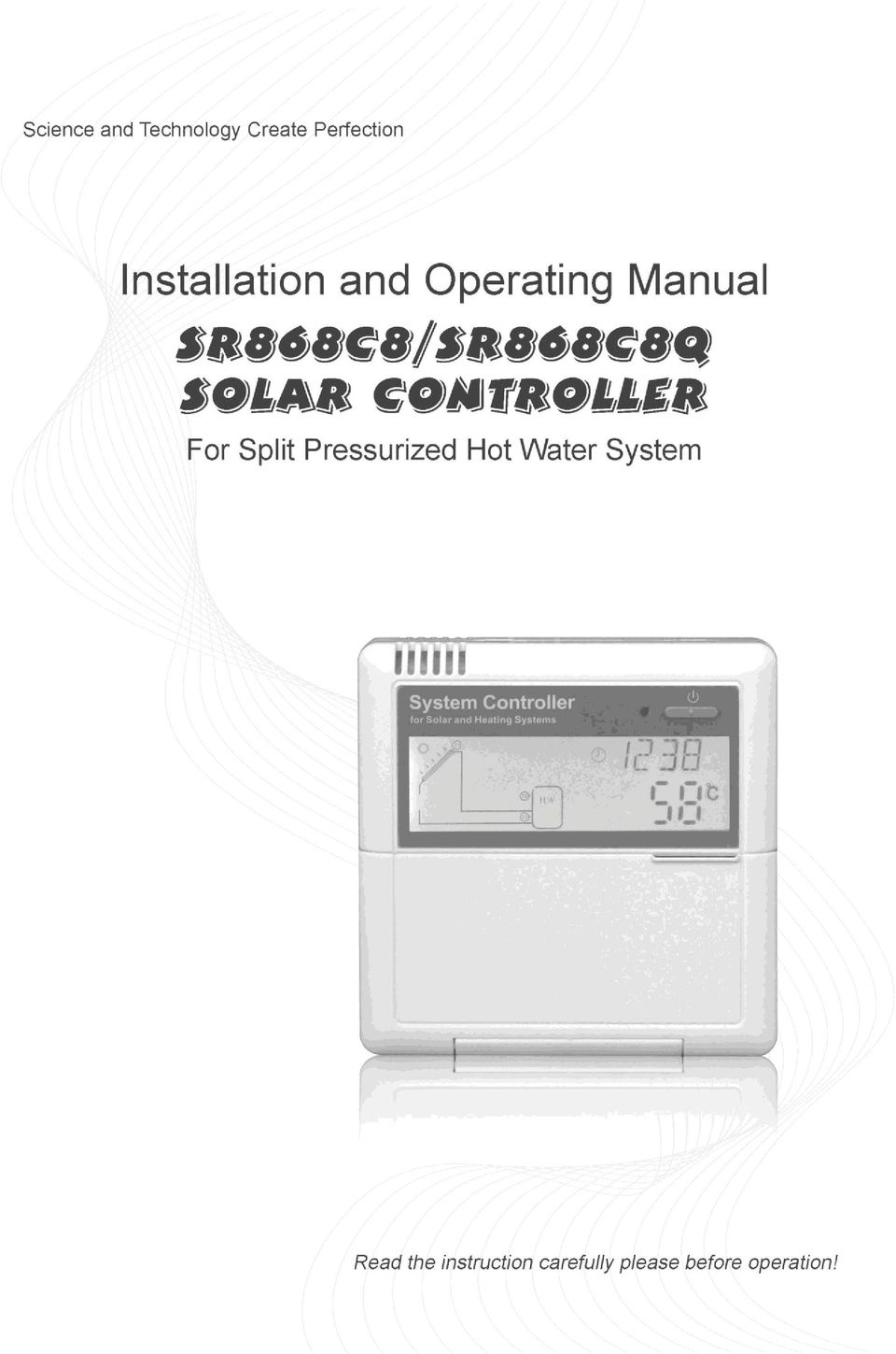
2 Contents Contents Safety information Installation and commissioning About this manual Liability waiver Important remark Description of symbols Description of operation button Installation Installing the display unit of controller Installing the control unit Preparing before wire connection Power connection Terminal connection Commissioning Set time/ week Menu structure Menu description System description Controller functions Access main menu Access submenu Main menu DT O & DT F Temperature difference function Main menu-thet timing heating TEMP Temperature main menu EM Emergency collector temperature (emergency switch-off temperature of collector) CMX Maximum limited collector temperature (collector cooling function) CMN low temperature protection of collector CFR frost protection of collector SMX Maximum temperature of tank REC Tank re-cooling function C-F Celsius and Fahrenheit temperature transferring FUN Auxiliary function DVWG Anti-Legionella function CIRC Temperature controlled hot water circulation pump nmin Solar circulation pump speed adjusting (RPM speed controlling) DTS standard temperature difference - 1 -

3 (for circuit pump s speed adjusting) RIS Temperature increase rate (for circuit pump speed adjusting) OHQM Thermal energy measuring FMAX Flow rate MEDT Type of heat transfer liquid MED% Concentration of heat transfer liquid INTV Pump interval function tstp Pump interval- time trun Pump running time BYPR High temperature by-pass function (tank temperature automatically adjusting) HND Manual mode PASS Password setting LOAD Recovery to factory setting ON/OFF button Holiday function Manual heating Temperature query function Protection function Memory Protection Anti-dry heating Protection Screen protection Troubles Shooting Trouble protection Trouble checking Quality Guarantee Technical data Delivery scope Device matchable to this controller

4 1. Safety information 1.1 Installation and commissioning - When laying cables, please ensure that no damage occurs to any of the constructional fire safety measures presented in the building. The controller must not be installed in rooms where easily inflammable gas mixtures are present or may occur. The permissible environmental conditions can t be exceeded at the site of installation. Before connecting the device, make sure that the energy supply matches the specifications that controller requires. All devices connected to the controller must conform to the technical specifications of the controller. All operations on an open regulator are only to be conducted cleared from the power supply. All safety regulations for working on the power supply are valid. Connecting and /or all operations that require opening the regulator (e.g. changing the fuse) are only to be conducted by specialists. 1.2 About this manual This manual describes the installation, function and operation of a solar thermal controller. When installing the remaining components e.g. the solar collectors, pump assemblies and the storage unit, are sure to observe the appropriate installation instructions provided by each manufacturer. Only trained professional personnel may only perform installation, electrical connection, commissioning and maintenance of the device. The professional personnel must be familiar with this manual and follow the instructions contained herein. 1.3 Liability waiver The manufacturer cannot monitor the compliance with these instructions or the circumstances and methods used for installation, operation, utilization and maintenance of this controller. Improper installation can cause damages to material and persons. This is the reason why we do not take over responsibility and liability for losses, damages or cost that might arise due to improper installation, operation or wrong utilization and maintenance or that occurs in some connection with the aforementioned. Moreover we do not take over liability for patent infringements or - 3 -

5 infringements occurring in connection with the use of this controller- on third parties rights. The manufacturer preserves the right to put changes to product, technical date or installation and operation instructions without prior notice. As soon as it becomes evident that safe operation is no longer possible (e.g. visible damage). Please immediate take the device out of operation. Note: ensure that the device cannot be accidentally placed into operation. 1.4 Important remark We have carefully checked the text and pictures of this manual and provided the best of our knowledge and ideas, however inevitable errors maybe exist. Please note that we can not guarantee that this manual is given in the integrity of image and text, they are just some examples, and they apply only to our own system. Incorrect, incomplete and erroneous information and the resulting damage we do not take responsibility. 1.5 Description of symbols Safety instruction: The safety instructions in the manual are marked with a warning triangle. They indicate measures, which can lead to personal injury and safety risks. Operation steps: small triangle is used to indicate operation step. Notes: Contains important information about operation or function. 1.6 Description of operation button - 4 -

6 2.Installation No. Button description 1 Power indicating light 2 On/off button 3 Clock button 4 Holiday button(sr868c8 have no such function) 5 Heating - manual heating button 6 Recovery button 7 ESC, exit program setup 8 SET confirm button 9 + Parameter adjust button 10 - Parameter adjust button 11 LCD display screen Controller can only be installed indoors, far away from dangerous place and away from the electromagnetic field. Controller should be equipped with an additional plug, which should have minimum 3mm distance between the pole of the plug or effective compliance with the provisions of the installation. For example, switch or fuse, please note that it should be separated between the wires, and use AC power. 2.1 Installing the display unit of controller Take away the back cover plate of display unit by screwdriver, see picture 1 Fix the back cover plate on wall; see picture 2, (Note: don t drill hole on the cover plate) Insert display into groove of back cover 12, installing the display unit on the back cover plate see picture 3 Picture 1 Picture 2 Picture Installing the control unit protection. Note: the controller can only be installed in an area having an adequate level of - 5 -

7 Fixing the hang-panel of controller Choose a suitable site Mark the position of hole Drill the fixing hole, insert the expansion screw Fix the hanging plate by using screw Press the control unit on the hanging plate 2.3 Preparing before wire connection Please switch-off the power net before opening the controller cover, and note the regulation of local electricity supply. Open/ close the cover of terminal Loosen the screw 12, move cover upwards and take away the cover Close the cover: downwards close cover fix cover by using screw Power connection Power can only be switched on when the house of controller is closed, an installer must make sure that the IP protection class of the controller is not damaged during installation. Depending on the type of installation, the cables may enter the device through the rear hole of the case 4or the lower side hole of the case 5 Cable come from the rear 4: remove the plastic flaps from the rear side of the case using an appropriate tool

8 Cable come from the below5: cut the left and right plastic flaps using an appropriate tool (e.g. knife) and break them out of the case. Notes: the flexible wire must be fastened on the case using the clamps provided 2.5 Terminal connection Before to open the terminal, please be sure to switch-off the power supplier and pay attention to the local electricity supply rules. Terminal layout Reset button:this button is on the terminal connection panel, when system program is out of working, press Reset to recover the program of system to the factory settings. Power connection Power connection terminal is: Input ports Ground line terminal is GND Display connection Port 1: connect red wire (+12V)Port 2: connect white wire ( COM) - 7 -

9 Port 3: connect black wire ( GND) Note: please lead wire into indoors, and fix the cable outdoors. Sensor input ports Input sensor ports T0, T1: for Pt1000 sensors, used for measuring the temperature of collector and measuring the heat output. Input sensor ports T2, T3, and T4: for NTC10K, B=3950 sensors, used for measuring the temperature of tank and pipe. Advice regarding the installation of temperature sensors: Only original factory equipped Pt1000 temperature sensors are approved for use with the collector, it is equipped with 1.5meter silicon cable and suitable for all weather conditions, the temperature sensor and cable are temperature resistant up to 280, not necessary to distinguish the positive and negative polarity of the sensor connection. Only original factory equipped NTC10K,B=3950 temperature sensors are approved for use with tank and pipe, it is equipped with 1.5meter PVC cable, and they are temperature resistant up to 105, not necessary to distinguish the positive and negative polarity of the sensor connection. All sensor cables carry low voltage, and to avoid inductive effects, must not be laid close to 230 volt or 400-volt cables (minimum separation of 100mm) If external inductive effects are existed, e.g. from heavy current cables, overhead train cables, transformer substations, radio and television devices, amateur radio stations, microwave devices etc, then the cables to the sensors must be adequately shielded. Sensor cables may be extended to a maximum length of ca. 100 meter, when cable s length is up to 50m, and then 0.75mm 2 cable should be used. When cable s length is up to 100m, and then 1.5mm 2 cable should be used. Output ports Output P1:For solar circuit pump, semiconductor relay (SCR relay), also suitable for RMP control, max. switching current 1A, Output P2:for hot water circuit pump, electromagnetic relay, and max. switching current 3.5A, R2 ports are always open, Output R1:for by-pass circuit pump or valve, electromagnetic relay, max. switching current 3.5A, R1 ports are always open, - 8 -

10 Output H1:for back-up electrical heater, electromagnetic relay, and max. switching current 10A, H1 connection ports are always open. 3. Commissioning Connect the sensors, pumps or switching valves to the controller before you connect the power supply! After switching on power to the controller, firstly it will ask for to set the time, password and parameters of system. 3.1 Set time/week Press Clock button, time displays on screen, hour selection area 00 blinks on display screen. Press + - button to set hour of clock Press Clock button again, minute area 00 blinks Press + - button to set minute of clock. Press Clock again, week area MO blinks Press + - button to set week. Press ESC button to exit set program, or wait for 20 seconds to exit program automatically. Code MO TU WE TH FR SA SU Week day Monday Tuesday Wednesday Thursday Friday Saturday Sunday - 9 -

11 3.2 Menu structure Menu of controller SR868C8Q Menu of controller SR868C8 Submenu: Through submenu, customer can set the parameter as desired value, please check it carefully

12 3.3 Menu description Code (Mainmenu) DT O DT F THET TEMP FUN HDN PASS LOAD Code (Subme nu) EMOF EMON CMX CMN CFR SMX REC C-F DVWG CIRC nmin OHQM INTV BYPA Code (Submenu) DTS RIS FMAX MEDT MED% tstp trun Menu Description Switch-on temperature difference Switch-off temperature difference Timing heating Temperature Collector maximum switch-off temperature Collector maximum switch-on temperature Maximum temperature of collector (Collector cooling function) Low temperature protection of collector Frost protection of collector Maximum temperature of tank Tank re-cooling function Celsius and Fahrenheit temperature transferring Auxiliary function Anti legionnaires' function Temperature controlled hot water circulation pump Speed controlling of circulation pump (RPM pump controlling) Standard temperature difference (for circulation pump speed adjust) Increase scale (circulation pump speed adjusting parameter set) Thermal energy measuring Flow rate Type of heat transfer liquid Concentration of heat transfer liquid Pump interval function Pump interval time Pump running time By pass (high temperature) Manual controlling Password set Recovery to factory set Remark Only available on controller SR868C8Q
")
13 3.4 System description 1 collector array 1 storage tank 1 pump and auxiliary heating Description: The solar circuit pump (P1) is switched on as soon as the switch-on temperature difference ( Ton) between the collector array (T1) and the storage tank (T2) is reached. If the temperature difference between the collector array (T1) and storage tank (T2) drops below the switch-off temperature difference ( Toff), or the temperature of storage tank (T3) reaches the preset maximum storage temperature, then the solar circuit pump ( R1) is switched off. Back-up heating by auxiliary boiler (detailed see paragraph 4.4): Within the preset time section of back-up heating, if the temperature T3 is below the switch-on temperature, then the circulation pump ( H1) of back-up heating is triggered, when T3 is heated to the switch-off temperature, circulation pump H1 of back-up heating is ceased. Note: T3 is alternative sensor, when no sensor (T3) is installed in the top part of tank, controller will use the signal of sensor T2 automatically to control the auxiliary heating or the circulation pump. T0: Temperature sensor for thermal energy measuring ( optional sensor) T1: Temperature sensor for collector array (PT1000) T2: Temperature sensor in the bottom part of tank 1(NTC10K)
 is switched off. Back-up heating by auxiliary boiler (detailed see paragraph 4.")
14 T3: Temperature sensor in the top part of tank (NTC10K,optional sensor) T4: Temperature sensor on hot water circulation pipe (NTC10K,optional sensor) P1: Solar circuit pump P2: Hot water circuit pump (optional output) R1: High temperature by-pass pump or valve (optional output) H1: output for back-up electrical heater 4.Controller functions 4.1 Access main menu Under standby status, doing like following access main menu Press SET button, PWD 0000 displays on screen, the left first digital blinks, ask for entering password, factory default set password is 0000 Press + - button to enter first digital of password. Press SET button again, the second digital blinks Press + - button button, to enter second digital of password Press SET button again, the third digital blinks Press + - button to enter the third digital of password Press SET button again, the fourth digital blinks Press + - button, to enter the fourth digital of password Press SET button again to access main menu Press + - button, can select the main menu Press ESC button to exit main menu 4.2 Access submenu After selecting main menu, do like following access submenu Press SET button, to access submenu Press + - button to select submenu Press SET button again to access program, can adjust parameter value now Press + - button, to adjust the value of parameter Press ESC button, exit program of submenu Press ESC button again, to exit main menu. For example: submenu

15 4.3 Main menu DT O & DT F Temperature difference function Description: Solar circuit pump P1 is triggered by the temperature difference function, so long as the temperature difference between collector and tank reaches the switch-on DT, solar circuit pump is triggered. For example: the switch-on DT is 8 o C, switch-off DT is 4 o C, if the temperature in the bottom part of tank is 20 o C, then just when collector temperature rises up to 28 o C, pump is triggered, and when collector temperature drops to 24 o C, pump is ceased. Note: the switch-on/off DT of 8 o C and 4 o C are standard system setting according to many years experience, only in special application cases it needs to be changed, (e.g far distance heat transferring), normally it is recommend to use default set. Switch-on and switch-off DT are alternating set. To avoid mistake the minimum difference between two temperature differences (ΔTon ΔToff) is set as 2 o C. Setup the switch-on temperature difference: Under standby status, access main menu DT O, Press SET button, to access settings program of DT O, DT O 08 displays on screen, 08 blinks, the switch-on temperature difference can be set. Press + - button, to adjust the value of switch-on DT, adjustable range (OFF+2 )~20,factory setting is 8 Press ESC button to exit this setting, parameter is saved automatically. Setup the switch-off temperature difference: Under standby status, access main menu DT F Press SET button, to access settings program of DT F, DT F 04 displays on screen, 04 blinks, the switch-off temperature difference can be set. Press + - button to adjust the value of switch-off DT, adjustable range 0 ~ (ON-2 ),factory set is 4. Press ESC to exit menu, or wait for 20 seconds to exit automatically, the setup parameters are saved automatically

16 4.4 Main menu - THET timing heating Description: Electrical heater, gas boiler or oil boiler can be integrated into solar system used as back-up of system, and they can be triggered automatically at preset time by preset temperature. Within a preset time section, when the temperature (T3) of top part of tank drops below the preset switching-on temperature of this function, back-up heating starts to work, when T3 rises up to the preset turning off temperature, back-up heating is stopped. Within 24 hours, three time sections can be set with this controller. Factory set: The first time section: back-up heating function starts at 4:00 and ends at 5:00 am. Within this time section, switch-on temperature is 40, switch-off temperature is 45. The second time section: from 10:00 to 10:00 am, it means there is no back-up heating in this time. The third time section: back-up heating function starts at 17:00 and ends at 22:00 pm. Within this time section, the switch-on temperature is 50, switch-off temperature is 55. The switch-on temperature adjustable range: 10 ~ (OFF-2 ) The switch-off temperature adjustable range: (ON+2 ) ~ 80 If you want to shut off one timing heating, then you can set the turning on time and turning off time same value (for example, the second time section no this function, then you can set turning on/off time is 10:00 ~ 10:00) When time is outside of the preset time section, back-up heating doesn t work automatically even when the tank temperature reaches the switch on temperature of heating. Note: When there is no sensor installed in the top part of tank (no T3 sensor), controller will take the signal of T2 (sensor in bottom of tank) automatically to control this function. The time in this controlled is 24 hours, when you set time section, the switch-off time of heating should be larger than switch-on time. For example: if you set the switch-on time of heating is at 17:00, but switch-off time of heating is 6:00, then this setting doesn t take effect, that means within this time section, heating function doesn t work. The correct set is like flowing: it should be divided into two time sections, one time section is from 17:00 to 23:59, the other time section is from 00:00 to 06:00. Under standby status, access main menu thet Press SET button, access THET program to set parameter, th 1o 04:00 displays on screen, the switch-on time and temperature for first time section of heating function

17 can be set Repress SET button, 04 of hour time blinks on screen Press + - button to adjust hour of time Repress SET button again, 00 of minute time blinks on screen Press + - button to adjust minute of time Repress SET button, temperature 40 blinks on screen Press + - button, to set the switch-on temperature of heating Then, Press ESC to exit this set and to access the switch-off time and temperature set Press + button, th 1F 05:00 displays on screen, the switch-off time and temperature for first time section of heating function can be set Press SET button, 05 of hour time blinks on screen. Press + - button to adjust hour of time Repress SET button, 00 of minute time blinks on screen Press + - button to set minute of time Repress SET button, temperature 45 blinks on screen Press + - button, to set switch-off temperature of heating Press ESC to exit this set program, parameters are saved automatically Press + button, th 2o 10:00 displays on screen, the switch-on time and temperature for the second time section of heating function can be set Press SET button, 10 of hour time blinks on screen Press + - button to adjust hour of time Repress SET button, 00 of minute time blinks on screen Press + - button to adjust minute of time Repress SET button, temperature 50 blinks on screen Press + - button to adjust switch-on temperature of heating Then press ESC to exit this set and to access the switch-off time and temperature set Press + button, th 2F 10:00 displays on screen, set the switch-off time and

18 temperature of second time section of heating function Press SET button, 10 of hour time blinks on screen Press + - button to adjust hour of time Repress SET button, 00 of minute time blinks on screen Press + - button to adjust minute of time Repress SET button, temperature 55 blinks on screen Press + - button, to adjust switch-off temperature of heating Press ESC to exit this set program, parameter is saved automatically Press + button, th 3o 17:00 displays on screen, set the switch-on time and temperature of the third time section of heating function Press SET button, 17 of hour time blinks on screen Press + - button, to adjust hour of time Repress SET button, 00 of minute time blinks on screen Press + - button, to adjust minute of time Repress SET button, temperature 50 blinks on screen Press + - button, to adjust switch-on temperature of heating Press ESC to exit this set program and to the switch-off time and temperature set Press + button, th 3F 22:00 displays on screen, the switch-off time and temperature of the third time section of heating function can be set Press SET button, 22 of hour time blinks on screen Press + - button, to adjust hour of time Repress SET button, 00 of minute time blinks on screen Press + - button to adjust minute of time Repress SET button, temperature 55 blinks on screen Press + - button to adjust switch-off temperature of heating Press ESC to exit menu, or wait for 20 seconds, set parameters are saved automatically Note: when no gas or oil boiler is installed in system, electrical heater can be installed as back-up device, when electrical heater is in operation status, signal blinks on screen

19 If customer use electrical heater as back-up, please according to the power of electrical heater to equip corresponding safety devices like contactor and breaker with this controller, we strongly recommend equipping with SR801 device with this controller, (SR801 detailed technical data see paragraph 10 spare parts) 4.5 TEMP Temperature main menu For every system, the factory set parameters are in the best condition that is fully integrated into the entire solar system. But these parameters can also be set individually to cater the special requirements, please carefully observe the operation data of system components after setting. Note: parameters that can be set depend on the selected system, not all the parameters can be adjusted in a solar system. Following submenu can be access though TEMP main menu. EM Emergency collector temperature (Emergency switch-off temperature of collector) CMX Maximum limited collector temperature (collector cooling function) CMN low temperature protection of collector CFR frost protection of collector SMX Maximum temperature of tank REC Tank re-cooling function C-F Celsius and Fahrenheit temperature transferring Function EMOF Collector maximum switch-off temperature EMON Collector maximum switch-on temperature Adjustable range (ON+3 )~ 200 OFF-3 )~ 197 Factory set Function exit temperature CMX Maximum limited collector temperature 110 ~ (collector cooling function) CMN low temperature protection of collector 0 ~90 OFF CFR frost protection of collector -10 ~10 OFF SMX Maximum temperature of tank 2 ~ REC Tank re-cooling function OFF C-F Celsius and Fahrenheit temperature transferring o C ~ o F o C

20 4.5.1 EM Emergency collector temperature(emergency switch-off function) Function description: When temperature of collector rises up to the preset maximum switch-off temperature, collector emergency switch-off function is activated. As the result of this function, solar circulation pump is stopped,it avoids the damage of system components caused by over-heated temperature. EMOF parameter is for set maximum switch-off temperature of collector (factory set: 130 o C), if the collector temperature rises up to preset EMOF temperature, solar pump is stopped;emon parameter is for set maximum switch-on temperature of collector (factory set: 120 o C),when the collector temperature drops to EMON temperature, solar pump can be triggered again, collector emergency switch-off function is deactivated automatically. EMOF collector maximum switch-off temperature Select submenu EMOF, EMOF 130 o C displays on the screen. Press SET button, parameter 130 o C blinks on the screen. Press +, - button, to adjust the EMOF temperature, adjustable range: ( ON +3 o C)~200 o C, factory set is 130 o C. Repress SET button, activate and deactivate this function, if deactivate the function, EMOF displays on screen. Press ESC button to exit menu, or wait for 20 seconds to exit automatically, set parameter is saved automatically. EMON collector maximum switch-on temperature Select submenu EMON, EMON 120 o C displays on the screen. Press SET button, parameter 120 o C blinks on the screen. Press +,- button, to adjust the EMON temperature, adjustable range: ( OFF-3 o C)~200 o C, factory set is 120 o C. Repress SET button, activate and deactivate this function, if deactivate the function, EMON- - - displays on screen. Press ESC button to exit menu, or wait for 20 seconds to exit automatically, set parameter is saved automatically. These two signals display on the screen, means collector emergency switch-off function is activated, and tank temperature rises up to its maximum permitted temperature. Only this signal displays on the screen, means this function is activated, but tank temperature doesn t rise up to its maximum temperature
,when the collector temperature drops to EMON temperature, solar pump can be triggered again, collector emergency switch-off")
21 4.5.2 CMX Maximum limited collector temperature (collector cooling function) Function description: The collector cooling function delays the vaporization of the heat transfer fluid. Shortly before reaching the maximum temperature of the collector, the solar pump starts working in order to cool down the heat transfer fluid using the heat losses occurring in pipelines and storage cylinder. When tank temperature rises to its preset maximal temperature, solar circuit pump is ceased compulsively even the temperature difference is satisfied. If the sunshine is very good, as a result collector temperature will rise continuously, when collector temperature rises up to its maximal temperature, solar pump will be triggered again even at the case that tank temperature is already to its maximal temperature. And solar pump works until the temperature of collector drops since this reversed circulation or when tank temperature rises its emergency temperature (95 o C). When displays, and blinks on the screen, it indicates that tank emergency temperature reaches, tank temperature is 95 To access main menu TEMP, then select submenu CMX CMX 110 displays on screen Press SET button, parameter 110 blinks. Press + - button, to adjust the collector protection temperature, adjustable range (100 ~190 ), factory set is 110 Repress SET button, activate and deactivate this function, if deactivate the function, CMX displays on screen. Press ESC button to exit the menu or wait for 20 seconds to exit automatically, parameters are saved automatically. CMX signal displays on screen, it indicates that this function is in activated CMN low temperature protection of collector Description: When the temperature of collector is below preset CMN temperatures, solar circuit pump is ceased, even when the temperature difference between collector and tank
22 exceeds switch-on temperature difference, solar pump doesn t work yet. When temperature of collector is 3 o C higher that the preset CMN temperature, solar circuit pump is restarted, controller exits this program. To access main menu TEMP, then select submenu CMN, CMN displays on screen, default set is off. Press SET button, default off signal blinks on screen. Repress SET button, to activate and deactivate this function Press + - button, to adjust the low protection temperature of collector CMN, adjustable range (00 ~90 ), after activate the function, factory set is 10 Press ESC button to exit the menu or wait for 20 seconds to exit automatically, parameters are saved automatically. CMN signal displays on screen, it indicates that this function is in activated CFR frost protection of collector Description: In winter when the temperature of collector is below the preset frost protection temperature (factory set is 4 o C), Solar circuit pump is triggered. Besides when tank temperature (T2) drops to 4 o C, electrical heater is triggered automatically and it is in operation until T2 is heated up to 20 o C or it is stopped when program of CFR is exited. When collector temperature rises up to 7 o C, solar circuit pump is ceased, program of CFR exits automatically. This function is used in system, which use water as heat transfer liquid, to avoid the freezing of solar heat transfer fluid. To access main menu TEMP, then select submenu CFR, CFR displays on screen, default set is off. Press SET button, default off blinks. Repress SET button, to activate or deactivate this function
23 Press + - button, to adjust the frost protection function, adjustable range is (-10 ~10 ), after function activated, default set is 4 Press ESC button to exit the menu or wait for 20 seconds to exit automatically, parameters are saved automatically. CFR signal displays on screen, it indicates that this function is in activated. Note: this function is only available in special solar system which using no-anti-freezing liquid; this kind of system is only suitable in area where the ambient temperature is near to 0 o C in only few days. If safety requirement is very high, then anti-freezing is necessary, we suggest to use suitable anti-freezing liquid to avoid frost problem SMX Maximum temperature of tank Description: When the DT between collector T1 and Tank 2 caters the switch-on DT of circulation, solar pump is triggered, but in order to avoid the high temperature inside tank, controller will check whether the temperature (T3) of top part of tank is higher than maximum temperature of tank, when T3 is higher than preset SMX temperature, solar pump is ceased even at the case that DT caters condition. When tank temperature drops and is 2 o C below the SMX, solar pump restarts when DT caters condition. To access main menu TEMP, then select submenu SMX, SMX 60 displays on screen. Press SET button, parameter 60 blinks Press + - button to adjust the value of maximum temperature of tank1 adjustable range is(2 ~95 ), default set is 60 Repress SET button to activate and deactivate this function, if function deactivated, SMX displays on the screen. Press ESC button to exit the menu or wait for 20 seconds to exit automatically, parameters are saved automatically. SMX signal displays on screen, it indicates that this function is in activated REC Tank re-cooling function Description: If tank temperature is over tank s maximum temperature, and at the same time, collector temperature is 5 o C lower than tank temperature, then solar pump is triggered, through this reversed circulation, tank temperature is reduced by heat loss occurs in
24 collector, solar pump keep in working until tank temperature drops below its maximum temperature. To access main menu TEMP, then select submenu REC, REC OFF displays on screen, default set is off. Press SET button, parameter OFF blinks on screen Repress SET button to activate or deactivate this function, after function activated; factory set is REC ON Press ESC button to exit the menu or wait for 20 seconds to exit automatically, parameters are saved automatically. REC signal displays on screen, it indicates that this function is in activated C- F Celsius and Fahrenheit temperature transferring To access main menu TEMP, then select submenu C-F, C-F displays on screen. Press SET button, parameter blinks on the screen. Press + button, to select between Celsius and Fahrenheit temperature, factory set is Press ESC button to exit menu or wait for 20 seconds to exit automatically, parameters are saved automatically. 4.6 FUN Auxiliary function The auxiliary function of this controller can be set under FUN submenu; it is possible to activate several auxiliary functions at the same time. Note: Sometimes, your selected function needs an extra signal input to connect temperature sensor or an extra output to connect pump or electromagnetic valve. in FUN submenu, some functions are deactivated. Hence, for different system, activated or deactivated status for following auxiliary functions in submenu is also different
25 Example to explain: If you set thermal energy measuring parameter (OHQM) is off, that means this function is deactivated, then, FMAX, MEDT and MED% functions are disappeared in the submenu, only when this function (OHQM) is activated, they are just appear in the submenu. (See detailed in 3.2 menu structure) Following submenu can be accessed through menu FUN DVWG Anti-Legionella function CIRC Temperature controlled hot water circulation pump nmin Solar circuit pump speed adjusting(rpm speed controlling) DTS Standard temperature difference(for circuit pump speed adjusting) RIS Increase rate (for circuit pump speed adjusting) OHQM Thermal energy measuring FMAX Flow rate MEDT Type of heat transfer liquid MED% Concentration of anti-freezing liquid INTV Pump interval function trun Pump interval time tstp Pump running time BYPA High temperature by-pass function (tank temperature automatically adjusting) DVWG Anti-Legionella function Description: In order to avoid occurring bacteria in water tank when the temperature of tank is lower for a long time, controller will check the temperature of tank every 7 days in a period automatically, if the temperature of tank is never over 70 o C during this period, then at the factory set default time of 01:00 on the seventh day of the period auxiliary heating system is triggered automatically to heat water until it rises up to 70 o C, bacteria is killed by high temperature, whereafter function is deactivated. To access main menu FUN, then select submenu DVWG, DVWG OFF displays on screen. Default set is OFF
26 Press SET button, parameter OFF blinks on the screen. Repress + - button, DVWG ON blinks on the screen, function is triggered. Press ESC button to exit the menu or wait for 20 seconds to exit automatically, parameters are saved automatically CIRC Temperature controlled hot water circulation pump Description: Solar system can provide temperature-controlled hot water circulation function; this function needs an extra hot water circulation pump (connect output port P2) and a sensor, which is installed on the return pipe of hot water (connect input port T4). When the temperature signal of sensor T4 is less than the preset turning on temperature of circulation pump, the hot water circulation pump (P2) triggers and works till the temperature exceeds the turning off temperature. Factory set: the desired hot water temperature is 40 o C, when return temperature T4 drops to 35 o C, circulation pump P2 is triggered, when T4 rises up to 40 o C, circulation pump P2 is ceased. Condition for triggering hot water circulation pump: only when tank temperature T2 is 7 o C higher than the required hot water temperature, hot water circulation pump just can be triggered. Note: in order to avoid large measuring error, the sensor T4 on hot water return pipe should be installed 1.5m far away from tank. This function isn t available in all systems. To access main menu FUN, then select submenu CIRC, CIRC displays on screen, factory set is off. Press SET button, parameter blinks on screen. Repress SET button, parameter 40 blinks on screen Press + - button, to adjust the temperature of hot water return, adjustable range: 2 ~95 ), after function is activated, factory set is 40 Press SET button again, blinks on screen, function is deactivated
27 Press ESC button to exit the menu or wait for 20 seconds to exit automatically, parameters are saved automatically nmin Solar circuit pump speed adjusting(rpm speed controlling) Note: SR868C8 doesn t have this function Description: P1 output can be configured to function either as RPM controlled output or simple switch output. When this function is activated, the output is RPM controlled output; when parameter is set as nmin 100% the output becomes a normal switch output. Normal switch output: circuit pump speed controlling is deactivated, pump is operated with a fixed speed, and flow rate is not changed. RPM control output: (speed controlling is activated), the control system attempts to maintain a constant temperature difference between collector and tank. The pump performance is continuously adjusted and the volume flow pumped is increased or reduced, depending on the temperature difference. To access main menu FUN, then select submenu nmin, nmin 30 displays on screen. Press SET button, parameter 30 blinks on the screen Press + - button, to adjust speed of circuit pump, adjustable range (30~100%), factory set is 30% Press ESC button to exit the menu or wait for 20 seconds to exit automatically, parameters are saved automatically DTS Standard temperature difference(for circuit pump s speed adjusting) Note: SR868C8 doesn t have this function Description: When the switch-on temperature difference ( T ON) reaches, solar pump is triggered, and then within 20 seconds, pump speed reaches to its minimum speed (30%). Whereafter, controller checks continuously, when the standard temperature difference (DTS) reaches, the speed of pump increases one grade (10%), temperature difference RIS increases every 1 o C, speed of pump increases 10% until it reaches to its maximum speed 100%. Through setting the temperature difference increase rate (RIS) can
28 achieve the controlling of pump speed. If temperature difference drops to the switch-off TD( T OFF), circuit pump is ceased. To access main menu FUN, then select submenu DTS, DTS 08 o C displays on the screen Press SET button, parameter 08 o C blinks on the screen Press + - button, to adjust standard TD, adjustable range (2 ~30 ), factory set is 08 o C Press ESC button to exit the menu or wait for 20 seconds to exit automatically, parameters are saved automatically RIS Temperature increase rate (for circuit pump speed adjusting) Note: SR868C8 doesn t have this function To access main menu FUN, then select submenu RIS, RIS 01 o C displays on screen. Press SET button, parameter 01 o C blinks on the screen Press + - button, to adjust increase rate of (RIS)of temperature difference, adjustable range (1 ~20 ), factory set is 1 o C Press ESC button to exit the menu or wait for 20 seconds to exit automatically, parameters are saved automatically OHQM Thermal energy measuring Note: SR868C8 doesn t have this function Description: Controller has function for measuring the thermal energy; it can measure the energy which from collector transfers to tank. For the sake of measuring, the temperature (T0, T1) on going and return pipe should be checked, and an extra flow meter should be installed on the circulation pipe, it is used for measuring the flow rate. The thermal energy through solar system is calculated with measured parameter temperature T1, T0 and flow rate. Thermal energy get in the current day displays in
29 DKWh, accumulative thermal energy displays in kwh or MWh. To access main menu FUN, then select submenu OHQM, OHQM OFF displays on screen, Factory set is OFF Press SET button, parameter OHQM OFF blinks on the screen Repress + - button, to activate this function, OHQM on blinks on the screen Press ESC button to exit the menu or wait for 20 seconds to exit automatically, parameters are saved automatically. Note: 1) Thermal energy achieved in current day, accumulative thermal energy and operation time of pump can be reset, doing like following Operation steps: under standby status, doing like following Press + - button, select to check the thermal energy of current day, DKWH XX SET displays on the screen. Press SET button for 3 seconds, buzzer makes 3 times du - - -, the daily thermal energy is cleared, and daily thermal energy is reset to 00. Press + - button, select to check accumulative thermal energy, KWH XX or MWH XX SET displays on the screen. Press SET button for 3 seconds, buzzer makes 3 times du - - -, the sum thermal energy is cleared, accumulative thermal energy is reset to 00. Press + - button, select to check operation time of pump, hp XX SET displays on the screen. Press SET button for 3 seconds, buzzer makes 3 times du - - -, the operation time of pump is cleared, and it is reset to 00. 2) Only when the thermal energy balance function is activated, operation time of circulation pump function just can be triggered FMAX Flow rate Note: SR868C8 doesn t have this function FAMX: Flow rate L/min. adjustable range: (0.1~20) L/min, increase rate 0.1L per time, factory set is 2.0L/min
30 To access main menu FUN, then select submenu FMAX, FMAX 2.0 displays on screen. Press SET button, parameter 2.0 blinks on the screen Press + - button to adjust parameter of flow rate. adjustable range(0.1~20) Press ESC button to exit the menu or wait for 20 seconds to exit automatically, parameters are saved automatically MEDT Type of heat transfer liquid Note: SR868C8 doesn t have this function MEDT: type of heat transfer liquid, adjustable range (00~03), factory set :01 Type of heat transfer liquid: 00:Water 01:Propylene glycol 02:Glycol 03:Tyfocor LS/G-LS To access main menu FUN, then select submenu MEDT, MEDT 01 displays on screen. Press SET button, parameter 01 blinks on the screen Press + - button, to adjust type of heat transfer liquid, adjustable range (00~03) Press ESC button to exit the menu or wait for 20 seconds to exit automatically, parameters are saved automatically MED% Concentration of heat transfer liquid Note: SR868C8 doesn t have this function MED% Concentration of heat transfer liquid (volume percentage %), depending on the type of heat transfer liquid, adjustable range (20 ~70), factory set 40% To access main menu FUN, then select submenu MED%, MED% 40 displays on screen. Press SET button, parameter 40 blinks on the screen
31 Press + - button to adjust concentration, adjustable range (20~70) Press ESC button to exit the menu or wait for 20 seconds to exit automatically, parameters are saved automatically INTV Pump interval function Note: SR868C8 doesn t have this function Description: This function is useful when collector sensor isn t installed in collector (sensor installed on the outlet pipe of collector). In order to measure the actual temperature of collector, within the preset interval, solar pump is triggered like pulse, so that the hot water inside collector can flow to the pipe, where sensor is mounted, as the result, the actual temperature of collector is measured. It is unnecessary to activate this function in all time, you can use it within a preset time section, default set time is 06:00 ~20:00. During the period that solar pump is in operating, (the period of running time can be set by parameter trun ), controlled check the temperature signal of sensor, if the temperature increases less than 1 o C, then solar pump is ceased automatically. After the break time (interval can be set by parameter tstp ), same process repeats. During the period that solar pump is in operating, if measured temperature increases over 1 o C, then the next interval is omitted, this omitting repeats when it caters condition and until the switch-on temperature difference is catered or no more temperature can be measured. After that, pump interval function recovers to pulse rate-controlled mode. To access main menu FUN, then select submenu INTV, INTV OFF displays on screen. Press SET button, parameter OFF displays and blinks, factory set is OFF Press + - button, to activate this function, INTV ON displays on the screen. Press ESC button to exit the menu or wait for 20 seconds to exit automatically, parameters are saved automatically
32 tstp Pump interval- time Note: SR868C8 doesn t have this function To access main menu FUN, then select submenu tstp, tstp 30 displays on screen. Press SET button, parameter 30 blinks on screen, factory set is 30 minutes. Press + - button to adjust the loading time, adjustable range: 10~60 minutes, Press ESC button to exit the menu or wait for 20 seconds to exit automatically, parameters are saved automatically trun Pump running time Note: SR868C8 doesn t have this function To access main menu FUN, then select submenu trun, trun 10 displays on screen. Press SET button, parameter 10 blinks on screen, factory set is 15 second.. Press + - button to adjust the running time, adjustable range: 5~120 seconds Press ESC button to exit the menu or wait for 20 seconds to exit automatically, parameters are saved automatically BYPA High temperature by-pass function (tank temperature automatically adjusting) Description: High-temperature bypass role is independent of the solar system's operation; the extra thermal energy of tank can be transferred to other application through this function, as a result the constant tank temperature can be kept. In order to transfer this extra energy, it needs an extra pump or electromagnetic valve. (Connect to output port R3). For example: If we set the temperature of bypass is 70 o C, then when tank temperature (T2) rises up to 71 o C, this by-pass function is triggered, electromagnetic valve or circuit pump (R1) and TD controlled circuit pump (P1) will be triggered simultaneously. When tank temperature (T2) drops to 67 o C, electromagnetic valve or circuit pump (R1) and TD controlled circuit pump (P1) will be ceased simultaneously
33 To access main menu FUN, then select submenu BYPR, BYPR displays on screen. Press SET button, blinks on screen, default set is OFF Repress SET button, to activate by-pass function, BYPR 80 displays on the screen, 80 blinks Press + - button to adjust this parameter, adjustable range (5 ~120 ) Press ESC button to exit the menu or wait for 20 seconds to exit automatically, parameters are saved automatically. This signal displays on the screen, it indicates by-pass function is activated. Application example Picture1 Picture2 4.7 HND Manual mode When using this controller first time or when debugging this controller, output of this controller (P1,P2,R1,H1)can be triggered manually. On, OFF control. To access main menu HND, Press SET button, HND1 off displays on the screen, P1 output manually set Repress SET button, HND1 on displays on the screen, R1 output is switched-on Repress SET again, HND1 off
34 displays, P1 output is switched-off Press ESC to exit R1 set program Press + button, HND2 off displays on the screen, P2 output manually set Press SET button, HND2on displays on the screen, P2 output is switched-on Repress SET again, HND2off displays, R2 output is switched-off Press ESC to exit R2 set program Press + button, HND3 off displays on the screen, R1 output manually set Press SET button, HND3 on displays on the screen, R1 output is switched-on Repress SET again, HND3 off displays, R3 output is switched-off Press ESC to exit R3 set program Press + button, HND4 off displays on the screen, H1 output manually set Press SET button, HND4 on displays on the screen, H1 output is switched-on Repress SET again, HND4 off displays, R4 output is switched-off Press ESC to exit R4 set program Note: when manual mode is activated,signal displays on the screen, after 15 minutes all outputs are switched-off, controller exits manual mode automatically. 4.8 PASS Password setting To access main menu PASS,
35 Press SET button, PWDC 0000, the left digital blinks, ask for to enter the password, factory set is 0000 Press + - button to enter the first digital Repress SET button, the second digital blinks Press + - button to enter the second digital Repress SET button, the third digital blinks Press + - button to enter the third digital Repress SET button, the fourth digital blinks Press + - button to enter the fourth digital Press SET button, PWDN 0000 displays on the screen, ask for entering a new password, doing like above to enter the new password Press SET button, PWDG 0000 displays on the screen, ask for reentering the new password, doing like above to reenter the new password, PWOK displays on the screen to indicate reentering password successfully. Press ESC button to exit set program or wait for 20 seconds to exit automatically. Warning! If the password is forgot, it is not possible to recover, but you can recover the password to factory set, then you can reedit a password like above descript steps, doing like following to recover to factory set. Open cover in the front of the display,press and hold on,then repress the recovery button,which on the dispaly plate. Buzzer makes du times, then release button. Controller recovers to factory set, a new password can be reset now. 4.9 LOAD Recovery factory setting To access main menu REST, Press SET button, YES displays on the screen
36 Hold down SET button, buzzer makes du times, then release SET button. Controller recovers to factory set, new paramters can be reset now. Press ESC button to exit set program or wait for 20 seconds to exit automatically ON/OFF button Under the standby status, Press screen. Repress button for 3 seconds; controller is switched off, OFF displays on the button, controller is switched-on again Holiday function Note: SR868C8 doesn t have this function Description: This function activates in night, solar liquid will flow from storage tank to collector to cool the tank, and therefore to prevent high thermal loads problem of the solar system due to completely heated storage tank. The function is activated at night between 10 pm and 6 am, when the collector temperature drops 8 below the storage tank temperature (T2), solar circuit pump starts to work; when the temperature of collector is 2 below the tank temperature, and solar circuit pump is ceased. Activate this function if: You intend to be absent for an extended period (holiday) No hot water is required for an extended period. Note: The function is deactivated when the temperature in lower section of storage tank falls down to 35. Activate/ deactivate this function: Press Holiday button for a long time until the signal of holiday function displays on the screen, and then holiday function is activated. Repress Holiday button, signal disappears, holiday function is deactivated. Note: This function is only activated when you are not at home for long time, when you come back; please make sure to deactivate it
37 4.12 Manual heating Description: Electrical heater, gas or oil boiler can be as back-up devices in a solar system, this controller can achieve constant temperature controlling, when controller gets temperature signal of top part tank (T3) is 2 below the preset temperature, back-up heating will be triggered. When temperature of top part tank (T3) reaches to the preset temperature, heating is ceased. Conditions for triggering manual heating function: the setting temperature should be 2 higher than tank temperature. Activate/deactivate the function: Press Heating button, temperature 60 blinks on the screen. Press + - button to adjust switch-on temperature, adjustable range 10 ~80, factory set is 60. After 20 seconds, this function is activated, signal displays on the screen, and heating signal blinks also. Press Heating button again, to switch-off manual heating function. Note: manual heating can only heat tank one time, after manual heating is triggered, when temperature of tank rises up to the preset temperature, manual heating ceases, and manual heating function will be deactivated automatically, if customer wants to heat again, you need redo according to above steps Temperature query function Under standby status, Press + - button can check the value of temperature sensors T0~ T4, pump speed (n%), accumulative operation time of circuit pump (Hp), daily thermal energy (DKWH), accumulative thermal energy (KWH) or (MWH). When checking temperature, T0 T4 will displays one by one, corresponding sensor signal blinks. Press ESC button, week and tank temperature can be displayed. Note: Value of accumulative operation time of circuit pump (Hp), daily thermal energy
38 (DKWH) and accumulative thermal energy (KWH) or (MWH) can only be checked after triggering of OHQM thermal energy balance function. Press + - button can check the value of temperature sensors T1~ T4. 5. Protection function 5.1. Memory protection In case power failure occurs, controller keeps the parameter settings unchanged Anti- dry heating protection In case that no enough water is in tank when electrical heating is in operation, in order to avoid the damage of electrical booster caused by dry heating, controller will start the anti-dry heating protection, EE displays on screen and controller switches off all outputs (H1). In this case, it ought to switch off power supply, check and resolve the problems, and then switch on the power, controller restarts to work normally. 5.3 Screen protection When no any press on button for 3 minutes, screen protection is activated automatically, and then LCD lighting lamp is switched-off. Through press any button to light LCD lamp again. 6. Trouble shooting 6.1 Trouble protection a. When there is a break or short circuit between the connection of temperature sensors, controller switches off the corresponding functions and no more output signals are given, at the same time error signals are showed on the display. If control unit does not work correctly, please check following points. Press + - button to check error code, signal displays on the LCD screen
39 Error message on LCD screen T Meaning Cause of error Error rectification T0 sensor problem Sensor wiring interrupted, Check resistance not connected or short value, replace circuit Thermal Connect T0or measuring switch-off this T0 sensor not connected function is function switched-on (OHQM) T T1 sensor problem Sensor wiring interrupted, not connected or short circuit Check resistance value, replace T T2 sensor problem Sensor wiring interrupted, not connected or short circuit Check resistance value, replace T T3 sensor problem Sensor wiring interrupted, not connected or short circuit Check resistance value, replace T4 sensor problem Sensor wiring interrupted, not connected or short circuit Check resistance value, replace T hot water Install T4 or circulation pump T4 not installing switch-off this function turn-on function 6.2 Trouble checking The controller is quality product, conceived for years of continuous trouble-free operation. If a problem occurs, the cause of the problem very often lies not in the controller but in the peripheral components. The following description of some well-known problems should help the installer and operator to isolate the problem, so that the system can be place back into operation as quickly as possible and to avoid
40 unnecessary costs. Of course, not all possible problems can be listed here. However, most of the normal problems encountered with the controller can be found in the list below, only return the controller to seller when you are absolutely sure that none of the problems listed below is responsible for the fault. Symptoms Secondary symptoms Possible cause Procedure Controller does not appear to Display shows nothing, no display illumination Controller power supply is interrupted or Check the controller power cable Press reset button function at all program is out of work The solar pump doesn t The pump symbol in the display blinks Pump power supply is Check the pump power cable operate, despite the fact that switch-on conditions are satisfied interrupted Pump doesn t The pump symbol in The maximum No fault operate the display doesn t blink. Lighted storage tank temperature (SMX) has been reached The maximum or blinks collector temperature (EM) has been reached. T Error message displays on the screen Fault (short circuit or open circuit) in a temperature sensor On the controller, request the current values from all connected temperature sensors, replace all defective sensors and /or cabling
41 The solar The pump symbol in Holiday function or No problem, it is pumps the display blinks. Frost protection normal. If necessary operated, function or tank to deactivate the despite the re-cooling function corresponding fact that the is activated. functions. switch-on conditions are not satisfied. One function There is no function All inputs and No fault on controller can t be selection in submenu outputs are used; activated inputs and outputs can t be used doubly. Warning! Remove the device from the mains supply before opening the case A potentially defective sensor can be checked using an ohmmeter. To do this, the sensor must be disconnected, its resistance measured, and the value compared with the figures in the table below, small deviation (±1%) is acceptable, PT1000 resistance value Ω NTC 10K B=3950 resistance value Ω Quality Guarantee Manufacturer provides following quality responsibilities to end-users: within the period of quality responsibilities, manufacturer will exclude the failure caused by production and material selection. A correct installation will not lead to failure. When a user takes incorrect handling way, incorrect installation, improper or crud handling, wrong connection of sensor in system and incorrect operation, the quality responsibility is invalid for them. The warrantee expires within 24 months after the date of purchasing the controller
42 8. Technical data Type Specification SR868C8Q SR868C8 Appearance of controller 120mm 120mm 18mm 120mm 120mm 18mm Power supply AC230V±10% AC230V±10% Power consumption < 3W < 3W Accuracy of temperature measuring ±2 o C ±2 o C Range of collector temperature -10~220 o C -10~220 o C measuring Range of tank temperature 0~110 o C 0~110 o C measuring Suitable power of pump 3 个, 600W 3 个, 600W Suitable power of electrical heater 1 个, 1500W 1 个, 1500W Inputs Outputs 2 x Pt1000 sensor ( 500 o C) for collector (silicon cable 280 o C), 3 x NTC10K, B3950 sensor ( 135 o C) for tank, (PVC cable 105 o C), 3 relays, for circulation pumps or 3-way electromagnetic valve 1 relay for electrical heater 1 x Pt1000 sensor ( 500 o C) for collector (silicon cable 280 o C), 2 x NTC10K, B3950 sensor ( 135oC) for tank, (PVC cable 105 o C), 3 relays, for circulation pumps or 3-way electromagnetic valve 1 relay for electrical heater Ambient temperature -10~50 o C -10~50 o C Water proof grade IP40 IP
43 9. Delivery scope Type Lists SR868C8Q SR868C8 Display 1 1 Controller 1 1 Operation manual 1 1 PT1000 sensor (size:ф 6*50mm,cable length1.5m) 2 1 NTC10K(size:Ф 6*50mm,cable length1.5m) 3 2 Plastic expansion screw 5 5 Screw 5 5 Strain-relief clamp Device matchable to this controller Sensor for collector: high accuracy PT1000 sensor(a01) Parameter: PT1000, Ф 6X50mm Sensor for tank: high accuracy NTC 10K sensor (A02) Parameter: NTC10K,B=3950, Ф 6X50mm Thermowell of sensor: stainless thermowell ( A05) Parameter: 1/2' male thread, Ф 8X200mm. Contactor unit of high power: SR801 When user selects electrical heater as back-up device, we recommend using SR801 unit connecting controller and electrical heater. Technical data of SR801: Dimension: 250mmx185mmx130mm Power supply:ac110v / AC230V Suitable power: 6000W Available ambient temperature: -10 ~ 50 o C Water proof grade: IP
1. Safety information
 ---- Contents 1. Safety information... 4 1.1 Installation and commissioning... 4 1.2 About this manual... 4 1.3 Liability waiver... 4 1.4 Important remark... 5 1.5 Description of symbols... 5 1.6 Description
Manual of Solar Pump Station SR882 for Split Pressurized Solar Hot water System 2011.07.07
 Manual of Solar Pump Station SR882 for Split Pressurized Solar Hot water System 2011.07.07 Contents Solar pump station installation and operation manual Contents... 1 Solar pump station installation and
Operating manual For split pressurized solar hot water system controller
 Operating manual For split pressurized solar hot water system controller Model SR1188 2011.03.26 Contents Contents... 1 1. Safety information... 4 1.1 Installation and commissioning... 4 1.2 About this
1 General information
 1 General information 1.1 About this manual This manual describes the installation, function and operation of an integrated solar control system, which is suitable for split pressurized solar heating system.
Split Controller. User Manual SM-SS-F 2009/01/04
 Split Controller SM-SS-F User Manual 2009/01/04 Table of contents 1. Parts illustration.... 1 2. Electrical technical data...... 2 3. Electrical connection...3 4. Assemble parts...4 4.1 Assemble the fixed
EK908FHL - Thermostat for floor heating
 EK908FHL - Thermostat for floor heating EK908FHL is a programmable thermostat designed for floor warming application or helping to limit floor temperature. This thermostat can be used for hot water radiant
RESOL DeltaSol A. Mounting Connection Operation Examples. Manual
 RESOL DeltaSol A Mounting Connection Operation Examples www.resol.dedeltasol A Manual Thanks for buying a RESOL controller. Read this manual carefully to get the best performance from this unit. Contents
AN500T, AN1000, AN1000T, AN1500, AN1500T AN2000, AN2000T
 Product Instruction Manual Accona AN500T, AN1000, AN1000T, AN1500, AN1500T AN2000, AN2000T Panel heater v16.5/5 Version 3.2 Jan 2015 Contents 1. Important safety points 2. Installation 2.1. Wall mounting
ETHERNET IRRIGATION CONTROLLER. Irrigation Caddy Model: ICEthS1. User Manual and Installation Instructions
 ETHERNET IRRIGATION CONTROLLER Irrigation Caddy Model: ICEthS1 User Manual and Installation Instructions I R R I G A T I O N C A D D Y M O D E L : I C E T H S 1 User Manual and Installation Instructions
Drayton Digistat +2RF/+3RF
 /+3RF Programmable Room Thermostat Wireless Model: RF700/22090 Model: RF701/22092 Power Supply: Battery - Thermostat Mains - Digistat SCR Invensys Controls Europe Customer Service Tel: 0845 130 5522 Customer
Alpha Climatic Programmable Modulating Boiler Energy Manager. Installation and User Instructions
 Alpha Climatic Programmable Modulating Boiler Energy Manager Part No 3.022144 (Hard Wired) Part No 3.022143 (Radio Frequency) Installation and User Instructions 1. Description The Alpha Climatic energy
Sensi TM. Wi-Fi Programmable Thermostat MANUAL OPERATION. Version: March 2016 2016 Emerson Electric Co. All rights reserved.
 Sensi TM Wi-Fi Programmable Thermostat MANUAL OPERATION Version: March 2016 2016 Emerson Electric Co. All rights reserved. Contents MANUAL OPERATION GUIDE Buttons and Icons 3 Basic Functionality 4 Manual
ELECTRIC CENTRAL HEATING FLOW BOILER
 ELECTRIC CENTRAL HEATING FLOW BOILER EKCO.T Used product can t be treated as general communal waste. Disassembled appliance has to be delivered to the collection point of electrical and electronic equipment
Wireless 7 Day Programmable Room Thermostat
 Wireless 7 Day Programmable Room Thermostat Cat. No. TRT037 Transmitter Receiver Operating & Installation Instructions What is a programmable room thermostat? an explanation for householders A programmable
Art.S001-S002 SOLAR MODULE WITH DELIVERY AND RETURN CONNECTIONS
 Art.S001-S002 SOLAR MODULE WITH DELIVERY AND RETURN CONNECTIONS Technical Information sheet 0001/07/Rev01 ENG FUNCTION Series S001 and S002 circulation units are applied to the primary circuit of solar
AUTODIALLER / QUICKDIALLER - SA132
 AUTODIALLER / QUICKDIALLER - SA132 INSTRUCTION LEAFLET ENGLISH www.thermomax-group.com CONTENTS 1 SETUP AT A GLANCE... 2 2 FOREWORD....... 3 3 INSTALLATION...... 4 4 KEYPAD AND INDICATORS...... 5 SETTING
Owner s Guide Guide du propriétaire Guía para el usuario TH115-AF-GB-10. Programmable thermostat Thermostat programmable Termostato programable
 Owner s Guide Guide du propriétaire Guía para el usuario TH115-AF-GB-10 Programmable thermostat Thermostat programmable Termostato programable Read and save these instructions. Veuillez lire le mode d
GeyserWise TSE. thermostat instruction manual. SANS 181 compliant
 GeyserWise TSE thermostat instruction manual SANS 181 compliant Before operating and installation, carefully read all instructions. Do not discard this manual. Index Warranty Components About the GeyserWise
Max primary circuit temperature 90ºC Max primary circuit temp. 90ºC Max secondary circuit temperature 45ºC Max secondary circuit temp.
 EGLISH 1 Product description exchanger equipped with an electronic control unit and circulation pump for the primary circuit. All Aqua-Mex variants can be ordered with an interior coil of either titanium
RDJ10RF/SET. Wireless room temperature controller with 24-hour time switch and LCD. Programmable, for heating systems
 3 072 RDJ10RF RCR10/433 Wireless room temperature controller with 24-hour time switch and LCD Programmable, for heating systems RDJ10RF/SET Operating modes: Automatic, Comfort, Energy Saving, and Frost
GSM Alarm System User Manual
 GSM Alarm System User Manual For a better understanding of this product, please read this user manual thoroughly before using it. Quick Guider After getting this alarm system, you need to do the following
HERZ-Thermal Actuators
 HERZ-Thermal Actuators Data Sheet 7708-7990, Issue 1011 Dimensions in mm 1 7710 00 1 7710 01 1 7711 18 1 7710 80 1 7710 81 1 7711 80 1 7711 81 1 7990 00 1 7980 00 1 7708 11 1 7708 10 1 7708 23 1 7709 01
User manual. 086U6297 Rev. 9 EN
 User manual Atria Atria Duo Atria Duo Optimum Atria Optimum Comfort Diplomat Diplomat Duo Diplomat Duo Optimum Diplomat Duo Optimum G2 Diplomat Optimum Diplomat Optimum G2 086U6297 Rev. 9 EN Thermia Värme
Time Recorder. User Manual. PDF created with FinePrint pdffactory trial version www.pdffactory.com
 Time Recorder User Manual 1 (1) Specifications: 1. Power supply 100, 110, 200, 220, 230 V AC (as designated), 50/60 Hz, single phase. 2. Power consumption Normal 2W (MAX 30W) 3. Standard time signal Quartz
User manual. Atec. 086L0130 Rev. 1 EN
 User manual Atec 086L0130 Rev. 1 EN Thermia Värme AB reserves the right to make changes to components and specifications without prior notice. 2010 Thermia Värme AB. The Swedish language is used for the
AIR CONDITIONER INSTALLATION MANUAL
 INSTALLATION MANUAL AIR CONDITIONER Please read this installation manual completely before installing the product. Installation work must be performed in accordance with the national wiring standards by
Rain+Birdt. Simple To Set Timer (SST) Setup & Operation Instructions. English. 1-800- RAIN BIRD (800-724-6247) or visit www.rainbird.
 Setup & Operation Instructions. English. 1-800- RAIN BIRD (800-724-6247) or visit www.rainbird.") Rain+Birdt Simple To Set r (SST) Setup & Operation Instructions English Installation...2 Tools and Supplies Needed...2 Step 1. Mount r...2 Step 2. Connect Power...2 Indoor r...2 Outdoor r...2 Step 3. Connect
Rain+Birdt Simple To Set r (SST) Setup & Operation Instructions English Installation...2 Tools and Supplies Needed...2 Step 1. Mount r...2 Step 2. Connect Power...2 Indoor r...2 Outdoor r...2 Step 3. Connect
RF 1. Contents: Connecting diagram. Detailed information:
 Contents: Introduction UFH-ZONE-R UFH-EXTRAZONE -R Connection of a thermostat (UFH-THERM-R) o Joining of a thermostat with UFH-ZONE-R or UFH-EXTRAZONE-R Connection of a digital thermostat (UFH-THERM -RD)
T0118 T2118 T3118. Instruction Manual
 Programmable indoor transmitter of temperature T0118 Programmable indoor transmitter of atmospheric pressure T2118 Programmable indoor transmitter of temperature, relative humidity and other derived humidity
TRANSMITTER RECEIVER THESE INSTRUCTIONS APPLY IN THE UK ONLY THESE INSTRUCTIONS ARE TO BE LEFT WITH THE USER OR AT THE APPLIANCE. Digistat Optimiser
 FITTING AND OPERATING INSTRUCTIONS FOR DIGISTAT OPTIMISER PROGRAMMABLE 7 DAY ROOM THERMOSTAT SYSTEM General information is given in the users instruction leaflet despatched with the appliance and/or on
Installation Guide. VisionPRO. TH8000 Series. Need Help? This manual covers the following models. System Types
 Installation Guide VisionPRO TH8000 Series Touch-screen Programmable Thermostat This manual covers the following models TH8110U: For 1 Heat/1 Cool systems TH8320U: For up to 3 Heat/2 Cool systems TH8321U:
ecomax Instructions for use Wall hung room sealed fan assisted condensing boilers For the user
 For the user Instructions for use ecomax Wall hung room sealed fan assisted condensing boilers ecomax 63/ E ecomax 68/ E ecomax 6/ E ecomax 635 E ecomax 84/ E ecomax 88/ E ecomax 835 E GB Table of contents
Programmable Thermostat MODEL 3312026.XXX With Dehumidify 3312024.XXX With Out Dehumidify
 Comfort Control Center 2 Thermostat Operating Instructions Programmable Thermostat MODEL 3312026.XXX With Dehumidify 3312024.XXX With Out Dehumidify TABLE OF CONTENTS About your new thermostat Features...2
Vroom Hardware manual ver. 1.00 Code 114VROOHWE00. Vroom CANBUS USER INTERFACE WITH LCD GRAPHIC DISPLAY AND WITH TEMPERATURE AND HUMIDITY SENSOR
 Vroom CANBUS USER INTERFACE WITH LCD GRAPHIC DISPLAY AND WITH TEMPERATURE AND HUMIDITY SENSOR ENGLISH HARDWARE MANUAL ver. 1.00 CODE 114VROOHWE00 page 1 of 22 Important Important Read these instructions
INSTALLATION GUIDE. Card Reader & Controller with KIM Swipe Reader for Solitaire 850 / 950 / 850L Learnlok PK2930
 INSTALLATION GUIDE Card Reader & Controller with KIM Swipe Reader for Solitaire 850 / 950 / 850L Learnlok PK2930 Card Reader and Controller Model 3.5 with KIM Swipe Reader Table of Contents 1. Features..................................
Overheating limit control
 Pahlén electric heater Maxi Heat with digital control is a compact and effective heater for swimming pools. It consists of a glassfibre reinforced polypropylene tank containing resistance-type heating
User Manual THR840DUK Digital Thermostat
 User Manual THR840DUK Digital Thermostat 50051982-001 Rev. A WARNING: This product must be correctly installed and configured to work properly (see pages 12-24). If you are not experienced in wiring electrical
SERVICE MANUAL FOR 6535 SERIES TWO TON HIGH EFFICIENCY PACKAGED HEAT PUMPS
 SERVICE MANUAL FOR 6535 SERIES TWO TON HIGH EFFICIENCY PACKAGED HEAT PUMPS TABLE OF CONTENTS 1. Warnings...2 2. Accessibility Of Appliance...3 3. Unit Dimensions And Specifications...3 4. Unit Specifications
MOUNTING AND OPERATING INSTRUCTIONS
 MOUNTING AND OPERATING INSTRUCTIONS CF 51/55 1. Delivery CF 51/55-1 calculator with battery (optionally with mains power supply) - 1 wall mounting bracket - package with material for sealing, screws, wall
Zenith Solar thermal 4.5m pump station Installation manual
 Zenith Solar thermal 4.5m pump station Installation manual Product code: 20026145 INSTALLATION MANUAL WATER RETURN GROUP This instruction manual is an integral part of the installation and maintenance
User Guide Reflow Toaster Oven Controller
 User Guide Reflow Toaster Oven Controller Version 1.5-01/10/12 DROTEK Web shop: www.drotek.fr SOMMAIRE 1. Introduction... 3 2. Preparation of THE REFLOW CONTROLLER... 4 2.1. Power supply... 4 2.2. USB
Applied Electronics. Commercial Dimming System UPDATE NOTICE
 REV. A Applied Electronics Commercial Dimming System UPDATE NOTICE This notice is to inform the end user of an additional feature added to this DP12/2400 dimming unit. This unit has been outfitted with
Model: 616-146v2 Quick Setup Guide DC: 071015 Atomic Projection Alarm with Indoor and Outdoor Temperature
 Model: 616-146v2 Quick Setup Guide DC: 071015 Atomic Projection Alarm with Indoor and Outdoor Temperature Snooze/Backlight BUTTONS Time, Alarm with Snooze, & Calendar Projection Arm Rotates 180 Indoor/Outdoor
GSM HOME SECURITY SYSTEM
 Cell /Mobile phone home security system GSM HOME SECURITY SYSTEM Model : GSM-120 TABLE OF CONTENTS 1. FEATURES... 1 2. APPLICATION... 2 3. SPECIFICATIONS... 3 4. FRONT PANEL & LAYOUT DESCRIPTION...6 5.
INSTALLATION AND OPERATION MANUAL
 ECO-WORTHY INSTALLATION AND OPERATION MANUAL INSTALLATION AND OPERATION MANUAL www.eco-worthy.com ECO-WORTHY Solar tracker ECO-WORTHY 400 Solar Tracker Owner s Manual Manual User Installation instructions
ALL IN ONE. Heat Pump Water Heater
 ALL IN ONE Heat Pump Water Heater INSTALLATION AND OPERATION INSTRUCTIONS Please read this user s manual carefully before operate the unit. www.airtradecentre.com CONTENTS A. IMPORTANT REMARKS ------------------------------------------------------------------------------------------------
ELECTRONIC THERMOSTAT AND THERMOMETER With SPEED CONTROL
 148 OLD CONCORD TURNPIKE, BARRINGTON NH 03825 USA TEL (603) 868-5720 FAX (603) 868-1040 1-800-435-6708 E-Mail:[email protected] www.seafrost.com ELECTRONIC THERMOSTAT AND THERMOMETER With SPEED CONTROL
B/S/H/ Error codes and service programmes PH
 1 ERROR CODES AND APPLIANCE MESSAGES... 3 1.1 Complete overview of all error codes (in order)... 3 Automatic switch-off... 3 Display is dark and any individual LEDs are lit... 3 E 005... 3 E 011... 3 E
SERVICE INSTRUCTION R410A. WALL MOUNTEDtype INVERTER SPLIT TYPE ROOM AIR CONDITIONER. Models Indoor unit Outdoor unit
 SERVICE INSTRUCTION SPLIT TYPE ROOM AIR CONDITIONER WALL MOUNTEDtype INVERTER Models Indoor unit Outdoor unit ASYG07LECA ASYG09LECA ASYG12LECA ASYG14LECA AOYG07LEC AOYG09LEC AOYG12LEC AOYG14LEC R410A CONTENTS
Data logger. Installation and operating instructions. Read carefully before installation, commissioning and operation.
 Data logger Installation and operating instructions SOREL Connect Read carefully before installation, commissioning and operation 1.1. - Specifications Description of data logger Electrical specifications:
INSTALLATION & SERVICE MANUAL. Display Panel
 INSTALLATION & SERVICE MANUAL Display Panel The PowerLine EMS TM is a specialized power distribution and energy management system intended to be used in recreational vehicles. The Control Module is housed
12 Volt 30 Amp Digital Solar Charge Controller Installation & Operation Manual
 12 Volt 30 Amp Digital Solar Charge Controller Installation & Operation Manual This 30Amp charge controller is designed to protect your 12Volt Lead-acid or Gel-cell battery from being overcharge by solar
User s Manual Before using the inverter, you need to read and save the safety instructions.
 User s Manual Before using the inverter, you need to read and save the safety instructions. STI SERIES (STI200, STI300, STI500, STI700, STI1000) Power Frequency Pure Sine Wave Inverter The information
High Efficiency Vaporizing System and Highly Durable Heaters Ensure 25% Increased Output.
 High Efficiency Vaporizing System and Highly Durable Heaters Ensure 25% Increased Output. Modular Design for Easy, Cost Effective Maintenance. Standardized Interface Allows Interchangeable Control Modules
DUAL SENSING DIGITAL THERMOSTAT PRODUCT INSTRUCTIONS. Construction Automotive Industry
 DUAL SENSING DIGITAL THERMOSTAT PRODUCT INSTRUCTIONS www.rehau.com Construction Automotive Industry SCOPE This guide gives instruction regarding REHAU Programmable Digital Thermostat installation and operation.
Manual Ranging MultiMeter
 Owner s Manual Manual Ranging MultiMeter Model 82345 CAUTION: Read, understand and follow Safety Rules and Operating Instructions in this manual before using this product.! Safety! Operation! Maintenance!
Aerona Air Source Heat Pumps
 ADDENDUM to INSTALLATION INSTRUCTIONS for Aerona Air Source Heat Pumps DOC.87-05/05 Rev.04 March 2013 ATTENTION INSTALLERS - UPDATED INFORMATION! Your Grant Aerona Air Source Heat Pump has a number of
Technical Manual. FAN COIL CONTROLLER COOLING or HEATING ANALOG or PWM Art. 119914 631001A
 COOLING or HEATING ANALOG or PWM Art. 119914 631001A TOTAL AUTOMATION GENERAL TRADING CO. LLC SUITE NO.506, LE SOLARIUM OFFICE TOWER, SILICON OASIS, DUBAI. UAE. Tel. +971 4 392 6860, Fax. +971 4 392 6850
Operating Instructions DT, PRT, PRT/HW PRT-R, PRT-R2
 Operating Instructions DT, PRT, PRT/HW PRT-R, PRT-R2 Heatmiser UK td Tel: +44(0)1254 776343 Primrose House www.heatmiser.co.uk Primrose Street Darwen ancashire BB3 2DE Contents Contents 1 Installation
IN-OUT Thermometer with Cable Free Sensor and Clock
 IN-OUT Thermometer with Cable Free Sensor and Clock MODEL: RAR232 USER'S MANUAL INTRODUCTION Congratulations on your purchase of the RAR232 In-Out Thermometer with 433MHz cable free sensor and calendar
its ELECTRIC POSITION for electric heat, or set the units fan control appropriately to ELECTRIC or another appropriate setting.
 Troubleshooting Poor Temperature Regulation This page lists problems that may affect the temperature performance of your LUX thermostat with suggested resolutions. For more detailed information please
Model 53603. Owner s Manual. Español - P. 19 Français - P. 39
 Model 53603 Owner s Manual Español - P. 19 Français - P. 39 Table of Contents I. Introduction............................ 1 Sample Watering Plan.......................... 1 II. Installation...........................
HEAT PUMP PROGRAMMABLE THERMOSTAT
 HEAT PUMP PROGRAMMABLE THERMOSTAT SA PM 3 COOL TEMP Form 44014-01 r010408 Model 43168 Owners Manual 1 Congratulations! Heat Pump Programmable Thermostat Model 43168 THERMOSTAT CONTROLS Switches & Buttons...15
Luna 3 Comfort Troubleshooting Guide June 2008
 Luna 3 Comfort Troubleshooting Guide June 2008 For Technical Assistance Call: (800)461-4657 WARNING! THIS DOCUMENT IS INTENDED ONLY AS AN EDUCATIONAL TOOL This Troubleshooting Guide, and the instructions
SWIMMING POOL HEAT PUMP Owners Manual
 SWIMMING POOL HEAT PUMP Owners Manual This manual refers to the 17.0kw and 21.0kw models only. The heat pump unit is sold with a 1 year warranty. In addition there is a 2 year parts warranty on the compressor
USER MANUAL WARNING! CONTENTS MODEL 1 SPECIFICATIONS READ ALL INSTRUCTIONS BEFORE PROCEEDING. Non-Programmable Single Stage Heat/Cool Thermostat
 Builder MODEL 1010 Series Non-Programmable Single Stage Heat/Cool Thermostat USER MANUAL Compatible with low voltage single stage gas, oil or electric heating or cooling systems, including single stage
AutoRanging Digital MultiMeter
 Owner's Manual AutoRanging Digital MultiMeter Model No. 82139 CAUTION: Read, understand and follow Safety Rules and Operating Instructions in this manual before using this product. Safety Operation Maintenance
PART 8: FIELD WIRING. n WARNING NOTICE. Boiler Manual
 PART 8: FIELD WIRING A. INSTALLATION MUST COMPLY WITH: 1. National Electrical Code and any other national, state, provincial or local codes or regulations. 2. In Canada, CSA C22.1 Canadian Electrical Code
AGRI-ALERT 800T / AGRI-ALERT 800 ALARM SYSTEM USER MANUAL
 AGRI-ALERT 800T / AGRI-ALERT 800 ALARM SYSTEM USER MANUAL Manufacturer: Viatron Electronics 3514 1st Street, St-Hubert (Quebec) Canada J3Y 8Y5 WARNING: the warranty can be void if the Agri-Alert 800T or
Contents. Introduction
 TION Contents Introduction...1 Basics...2 Main Menu Structure...3 Time Schedule Menu...4 Settings Menu...5 Reports Menu...6 Date / Time Adjustment Menu...7 Introduction TION is an advanced control device
THERMONET UNDERFLOOR HEATING STANDARD THERMOSTAT KIT STOCK CODE 5260
 THERMONET UNDERFLOOR HEATING STANDARD THERMOSTAT KIT STOCK CODE 5260 STANDARD THERMOSTAT KIT 1.0 KIT CONTENTS Parts included: 1 x Thermostat 1 x Wall plate 2 x Mounting box screws 1 x Floor temperature
Service manual. Website: www.andico.com.au CAUTION - BEFORE SERVICING THE UNIT, READ THE SAFETY - PRECAUTIONS IN THIS MANUAL.
 Website: www.andico.com.au Service manual CAUTION - BEFORE SERVICING THE UNIT, READ THE SAFETY - PRECAUTIONS IN THIS MANUAL. - ONLY FOR AUTHORISED SERVICE PERSONNEL. MODELS: MPK1-09CR-QB8 MPK1-12ER-QB6
LG Air Conditioning Multi F(DX) Fault Codes Sheet. Multi Split Units
 Fault Codes Sheet. Multi Split Units") Multi Split Units If there is a fault on any LG Multi unit, an Error mark is indicated on the display window of the indoor unit, wired-remote controller, and LED s of outdoor unit control board. A two
Multi Split Units If there is a fault on any LG Multi unit, an Error mark is indicated on the display window of the indoor unit, wired-remote controller, and LED s of outdoor unit control board. A two
REMOTE CONTROL MANUAL
 REMOTE CONTROL MANUAL ENGLISH CONTENT PRECAUTIONS...1-2 USING THE REMOTE CONTROL UNIT...3 OPERATION...4-9 Thank you for purchasing our Room Air Conditioner. Before using your air-conditioner, please read
RVR Hybrid System Installer Instructions - 10052012. RVR Hybrid System Controller Installation Instructions
 RVR Hybrid System Controller Installation Instructions 1 Introduction to Hybrid Systems The RVR Hybrid system uses a combination of the Immergas Audax range of heat pumps with gas or oil boilers to create
LK Electric Boiler - 4,5
 LK Electric Boiler -, Design LK Electric Boiler, kw is a wall-mounted electric boiler, intended primarily for low-temperature heating systems, e.g. under floor heating. LK Electric Boiler, kw is delivered
PRODUCT PRODUCT CODE TECHNICAL INSTRUCTIONS PAGE
 Table of Contents PRODUCT PRODUCT CODE TECHNICAL INSTRUCTIONS PAGE # Electric Room Comfort Controller NEW! RDY2000 Room Comfort Controller RDY 129-905 D-3 Electric for Specialized Applications Surface
INTELLIGENT CONTROL MODULE SA-2000-II HARDWARE MANUAL. Access Technologies International, Inc.
 SA-2000-II HARDWARE MANUAL Access Technologies International, Inc. 1 Table of Contents 1. Introduction 3 2. Features 3 3. Specification 4 4. Identifying Supplied Parts 4 5. Panel Description 5 6. Connection
Failure code manual. content
 Failure code manual content 一 wall split AC series 2 二 floor standing AC series. 4 三 portable AC series.. 5 四 dehumidifer 6 五 DC inverter single split series...7 六 DC inverter multi-split series 10 1 一
Technical Information
 Technical Information Interface with DDC 6 720 642 841-00.1RS Logamatic LON-Gateway For heating contractors during project planning 6 720 643 554 (11/2010) US/CA Contents Contents 1 Explanation of symbols
INSTALLING A/C ADAPTER
 WS 6502 INTRODUCTION 1. SNOOZE/LIGHT BUTTON 2. BASE 3. ALM SET BUTTON 4. + / C/F BUTTON 5. HISTORY BUTTON 6. MODE BUTTON 7. CHANNEL BUTTON 8. - / RCC BUTTON 9. MAX/MIN BUTTON 10. BATTERY COMPARTMENT 11.
ENGLISH INSTRUCTION & INSTALLATION MANUAL DUCTLESS MINI SPLIT AIR CONDITIONING SYSTEMS
 ENGLISH INSTRUCTION & INSTALLATION MANUAL DUCTLESS MINI SPLIT AIR CONDITIONING SYSTEMS Céliera Corporation. All rights reserved. Unauthorized duplication, reproduction prohibited. CONTENTS SAFETY PRECAUTIONS...
Operation Guide 3M-22
 Operation Guide 3M-22 TEMP UP Target Temp Time Reset TEMP DOWN Control Panel Heat/Cool Mode Switch Fan Switch Battery Compartment Statement of use: The 3M-22 can be used with - millivolt, 24VAC single
ELECTRIC POSITION for electric heat, then confirm with Fan Test below.
 Troubleshooting Poor Temperature Regulation This page lists problems that may affect the temperature performance of your LUX thermostat with suggested resolutions. For more detailed information please
RI-215A Operator s Manual. Part Number: 71-0045RK Revision 0 Released: 10/3/05
 RI-215A Operator s Manual Part Number: 71-0045RK Revision 0 Released: 10/3/05 Warranty RKI Instruments, Inc., warrants gas alarm equipment sold by us to be free from defects in materials and workmanship,
Daker DK 1, 2, 3 kva. Manuel d installation Installation manual. Part. LE05334AC-07/13-01 GF
 Daker DK 1, 2, 3 kva Manuel d installation Installation manual Part. LE05334AC-07/13-01 GF Daker DK 1, 2, 3 kva Index 1 Introduction 24 2 Conditions of use 24 3 LCD Panel 25 4 Installation 28 5 UPS communicator
What you can expect from your Solar Hot Water System
 Owner s Manual Your Solar Hot Water System Thank you for your investment in the FAFCO Solar Hot Water System. Since 1969 our goal has been to design, test, and produce solar heating systems that save you
PART 11: START-UP PROCEDURES FOR THE INSTALLER
 PART 11: START-UP PROCEDURES FOR THE INSTALLER NOTICE It is important to note that the user can adjust the heat curve down by adjusting the central heating temperature to a lower setting. 212 CENTRAL HEATING
SPY-BATT Battery Tutor Device Installation Manual Rev. 1.1-07/04/2016
 SPY-BATT Battery Tutor Device Installation Manual Rev. 1.1-07/04/2016 1. GENERAL DESCRIPTION The SPY-BATT is a device that allows to monitor the state of your battery. The SPY-BATT stores over time the
Technical data. Danfoss DHP-A
 Technical data Danfoss DHP-A An air heat pump which produces both heat and hot water Can operate efficiently down to -0 C Danfoss TWS tank gives plenty of hot water quickly and with low operating costs
Programmable Room Thermostat 7 Day (5-2 Day) Models: 22083 / 22087 Power Supply: Battery / Mains
 Models: 22083 / 22087 Power Supply: Battery / Mains") Drayton Programmable Room Thermostat 7 Day (5-2 Day) Models: 22083 / 22087 Power Supply: Battery / Mains Invensys Controls Europe Technical Helpline: +44 (0) 845 130 7722 www.draytoncontrols.co.uk Installation
Drayton Programmable Room Thermostat 7 Day (5-2 Day) Models: 22083 / 22087 Power Supply: Battery / Mains Invensys Controls Europe Technical Helpline: +44 (0) 845 130 7722 www.draytoncontrols.co.uk Installation
UM-X Field display for continous level sensors
 Technical Documentation Field display for continous level sensors 10/2007 Edition: 1 Item No.: 207120 FAFNIR GmbH Bahrenfelder Str. 19 D-22765 Hamburg Telephone: +49 (0)40-39 82 07-0 Fax: +49 (0)40-3 90
Installation instructions. For the competent person. Installation instructions. VRT 350f. VRT 350f GB, IE
 Installation instructions For the competent person Installation instructions VRT 350f VRT 350f GB, IE Legal information Document type: Product: Target group: Language: Installation instructions VRT 350f
Advantium 2 Plus Alarm
 ADI 9510-B Advantium 2 Plus Alarm INSTALLATION AND OPERATING INSTRUCTIONS Carefully Read These Instructions Before Operating Carefully Read These Controls Corporation of America 1501 Harpers Road Virginia
User manual. Solid (FR 98,),
,") User manual Solid (FR 98,), If these instructions are not followed during installation and service, Thermia Värme ABliability according to the applicable warranty is not binding. Thermia Värme AB retains
User manual Solid (FR 98,), If these instructions are not followed during installation and service, Thermia Värme ABliability according to the applicable warranty is not binding. Thermia Värme AB retains
BlueSolar Pro Remote Panel For BlueSolar PWM-Pro charge controllers 12/24V 5, 10, 20, 30A Article number SCC900300000
 Manual EN BlueSolar Pro Remote Panel For BlueSolar PWM-Pro charge controllers 12/24V 5, 10, 20, 30A Article number SCC900300000 Contents EN 1.Important safety instructions... 2 2. Installation... 2 3.Product
COMPUTHERM Q7 Programmable, digital room thermostat. Operating Instructions
 COMPUTHERM Q7 Programmable, digital room thermostat Operating Instructions GENERAL DESCRIPTION OF THE THERMOSTAT The COMPUTHERM Q7 type switched-mode room thermostat is suitable to regulate the overwhelming
Installation Guide. LR-HWLV-HVAC TouchPRO Wireless. System Types
 Installation Guide LR-HWLV-HVAC TouchPRO Wireless Touchscreen Thermostat System Types Gas, oil, or electric heat with air conditioning Warm air, hot water, high efficiency furnaces, heat pumps, steam,
USER MANUAL OPERATION AND USE OF CAR WITH. Diego G3 / NEVO SEQUENTIAL GAS INJECTION SYSTEM
 USER MANUAL OPERATION AND USE OF CAR WITH Diego G3 / NEVO SEQUENTIAL GAS INJECTION SYSTEM Page 2 z 7 Table of contents 1. STARTING THE ENGINE... 3 2. CONTROL PANEL... 3 2.1 Indication of the current level
User Guide. RX-406 LED Keypad For CAPTAIN-I Ver.5.5 & up
 RX-406 LED Keypad For CAPTAIN-I Ver.5.5 & up User Guide PIMA Electronic Systems Ltd. 5 Hatzoref Street, Holon 58856, Israel +972-3-6506444 +972-3-5500442 [email protected] http://www.pima-alarms.com