ORIONTM LIMITED USE / LIMITED APPLICATION ELEVATOR
|
|
|
- Antony Emil Phillips
- 9 years ago
- Views:
Transcription
1 ORIONTM LIMITED USE / LIMITED APPLICATION ELEVATOR Planning Guide Limited Use / Limited Application Elevator Applicable Codes: ASME A17.1, Section 5.2 CAN/CSA B44, Section 5.2 Part No m

2 TABLE OF CONTENTS GENERAL 3 PRODUCT DESCRIPTION 4 ORION LU/LA ELEVATOR SPECIFICATIONS 5 CAB TYPE SELECTION SHEET 6 MACHINE ROOM OPTIONS 7 MACHINE ROOM DIMENSIONS 8 HOISTWAY AND PIT ELECTRICAL NOTES 9 CONTROLLER TANK SPECIFICATIONS 10 ORION 48 X 54 TYPE 1 WITH 2 SPEED DOORS 11 ORION 48 X 54 TYPE 2 WITH 2 SPEED DOORS 12 ORION 48 X 54 TYPE 3 (4) WITH 2 SPEED DOORS 13 ORION 42 X 60 TYPE 1 WITH 2 SPEED DOORS 14 ORION 42 X 60 TYPE 2 WITH 2 SPEED DOORS 15 ORION 48 X 54 TYPE 1 WITH SWING DOORS 16 ORION 48 X 54 TYPE 2 WITH SWING DOORS 17 LOADS ON BUILDING AND PIT LOADING 18 ENTRANCE MOUNTING DETAILS FOR 2 SPEED DOORS WITH DRYWALL CONSTRUCTION 19 ENTRANCE MOUNTING DETAILS FOR 2 SPEED DOORS WITH DRYWALL CONSTRUCTION 20 ENTRANCE MOUNTING DETAILS FOR 2 SPEED DOORS WITH MASONRY CONSTRUCTION 21 ENTRANCE MOUNTING DETAILS FOR 2 SPEED DOORS WITH MASONRY CONSTRUCTION 22 2 SPEED AUTOMATIC DOOR AND GUIDE RAIL INFORMATION 23 PIT AND OVERHEAD CLEARANCE DETAILS 24 ORION STANDARD NOTES 25 SPECIFICATIONS FOR PART 5.3 COMPLIANCE Savaria Concord Lifts, Inc. Page 2 of 27

3 This planning guide is designed to assist architects, contractors and lift professionals in planning for a Orion Elevator to meet the requirements of the following codes and standards: ASME A17.1/CSA B , Section 5.2 ASME A17.1/CSA B , Section 5.2 ASME A , Addendum 2005, Section 5.2 ASME A17.1/CSA B , Section 5.2 ASME A17.1/CSA B , Addendum 2008, Section 5.2 ASME A17.1/CSA B , Section 5.2 ASME A17.1/CSA B , Section 5.2 This unique elevator is designed to help solve accessibility problems in commercial buildings, and meets state and national codes covering the Limited Use/Limited Application (LULA) elevators. We strongly recommend you contact the Authority Having Jurisdiction (AHJ) in the region where the equipment will be installed. Become familiar with all requirements governing the installation and use of elevators in public and private buildings. It is extremely important for you to know and adhere to all regulations concerning installation and use of elevators. Initial Release - September 1, 2006 Revised - May 22, 2008 Revised - December 4, 2009 Revised - March 12, 2010 Revised - November 3, 2010 Revised - December 7, 2011 Revised - November 14, 2012 Revised - July 9, 2013 Revised - August 19, 2013 Revised - October 21, 2013 Revised - November 29, 2013 Revised - March 12, 2014 Revised - October 21, 2014 Revised - November 5, 2014 Revised - January 13, 2015 Revised - January 29, 2015 Revised - February 4, 2015 Revised - February 19, 2015 Revised - March 10, 2015 Revised - September 24, 2015 Revised - October 15, 2015 Revised - March 7, 2016 Revised - March 7, 2016 GENERAL DOCUMENT REVISION HISTORY IMPORTANT NOTICE This Planning Guide provides nominal dimensions and specifi cations useful for the INITIAL planning of an elevator project. BEFORE beginning actual construction, be sure to receive application drawings customized with specifi cations and dimensions for your specifi c project. NOTE: The cab dimensions provided in this manual are based on a PLAM cab. Lift confi gurations and dimensions are in accordance with our interpretation of the standards set forth by AASME A Section 5.2 and CAN/CSA B Please consult Savaria or the authorized Savaria dealer in your area for more specifi c information pertaining to your project, including any discrepancy between referenced standards and those of any local codes or laws (AHJ). The dimensions and specifi cations in this Planning Guide are subject to change (without notice) due to product enhancements and continually evolving codes and product applications. Determine customer s intention for use. Determine code requirements of site. Determine installation parameters of site. Use page 6 to determine the car type and hoistway size requirements. Use pages 7, 8 and 25 to plan for machine room and electrical requirements. Page 3 of 27
 elevators.")
4 PRODUCT DESCRIPTION Overhead Clearance Hydraulic Cylinder Guide Rails ⅜ Wire Rope Cables Cab Operating Panel Cab Pit Orion in Hoistway Meets (ADA) Americans with Disabilities Act Requirements The Orion meets the requirements of the ADA Accessibility Guidelines as a means to provide public building access. Design Assistance With over 30 years of experience. Savaria has the expertise to provide solutions to practically every design challenge you face. Please call our Customer Service Department for professional advice at (800) or (905) Page 4 of 27

5 Load Capacity Rated Speed Power Supply (circuit by others) Lighting Supply (circuit by others) Drive System ORION LU/LA ELEVATOR SPECIFICATIONS 1400 lb (635 kg) 30 fpm (0.15 mps) 208 Volt, three-phase, 30 Amps, 60 Hz or 240 Volt, single-phase, 40 Amps, 60 Hz 115 Volt, 15 Amps, 60 Hz 1:2 cable hydraulic with slack cable safety device 5 hp submersed motor Two ⅜ diameter steel aircraft cables Rope wedge sockets Cab Size W48 x 54 x H84 (1219 mm x 1371 mm x 2134 mm), Type 1, 2, 3, 4 W42 x L60 x H84 (1067 mm x 1524 mm x 2134 mm), Type 1, 2, 3, 4 W51 x L51 x H84 (1295 mm x 1295 mm x 2134 mm), Type 3, 4 Cab Panel Finish Steel panel cab with optional laminates Maximum Travel 18 inches (457 mm) to 25 feet (7.6 m) ANSI, up to 40 feet residential and CSA Control System Automatic user interface; Programmable Logic Controller (PLC) Noise level (typical installation) 73.2 dba; measured at a height of 1m, distance of 1m, in front of tank, in closed machine room Daily cycle Maximum machine room temperature Levels and Openings Pit Depth Required Minimum Overhead Clearance Hall Station and Control Panel Finish Standard Features Options Normal: 30, Heavy: 75, Excessive: 100 Maximum starts in 1 hour on standard installation: 15 NOTE: Please consult your Sales Representative if there a chance you may exceed these amounts. 120 degrees F (49 degrees C); tank generating ~ 3200 BTU/HR to 6400 BTU/HR Up to 6 stops (maximum 6 landing doors on all cab types) 14 inches (355 mm) minimum up to 96 inches (2438 mm) 108 inches (2743 mm) Rectangular stainless steel (standard) or brass (optional) 8 lb/ ft or 16 lb/ft T-rail system Anti-creep device Architectual white ceiling Automatic cab ON/OFF lighting Car top stop switch and car top prop (where required) Data plates, capacity tags and rope tags Digital fl oor and directional indicator Emergency manual lowering, stop key switch and alarm buttons Emergency battery back-up for lighting, alarm and emergency lowering Floor specifi c battery lowering Illuminated cab operating buttons Limited warranty covers the repair or replacement of any defective parts for a period of 36 months from date of shipment Magnetic fl oor selection, stopping and re-levelling Manual reset slack rope safety switch Maintenance pit props Pit switch Pit clearance switch Presentation drawings Pump run timer Rail sections (8 ft standard or 16 ft optional) Recessed incadescent down lights in stainless steel or brass color Recessed plywood fl oor Two 12 V, 4 AH, sealed no maintenance batteries with 24 V, 4 Amp Smart Charge battery charge Variable speed pressure compensated valve with manual lowering Upper and lower terminal limits 2 speed sliding doors for drywall or Masonry hoistway fi nish 2 speed steel doors with infrared closing sensors in black, architectural white or stainless steel Steel panels with plastic laminate in a variety of colors 15 ft, 20 ft, or 25 ft hose with fl ow control 90 degree entry/exit cab Automatic cab gate operator and automatic hoistway door operator Automatic home landing to pre-selected fl oor Brass COP, hall call stations, handrail and recessed down lights Buffer springs, 15 (381 mm) minimum pit depth required Conductor cable for hoistway to pump wiring, 40 ft (12.19 m), 60 ft (18.29 m) or 80ft (24.38 m) Fire rated manual or automatic swing doors with automatic or manual accordion style cab gates (dependable on applicable code year) fi refi ghter service - phase 1 and 2 (dependable on applicable code year) Flow control, overspeed valve and pipe rupture valve Hands-free telephone Overspeed governor Fire recall service Raised plastic laminated panels in a choice of 7 colors Recessed stainless steel or brass telephone cabinet The Orion meets the requirements of multiple ASME A17 code years for a LU/LA Elevator. Contact sales for further information. Page 5 of 27
, Type 3, 4 Cab Panel Finish Steel panel cab with optional laminates Maximum Travel 18 inches (457 mm) to 25 feet (7.")
6 CAB TYPE SELECTION SHEET Type 1 Type 2 Type 3 and 4 IMPORTANT Finished hoistway dimensions must include the drywall. Determine the fi re rating of the hoistway, the type and layers of sheet rock and build only off the fi nal shop drawings specifi c to your project. Page 6 of 27

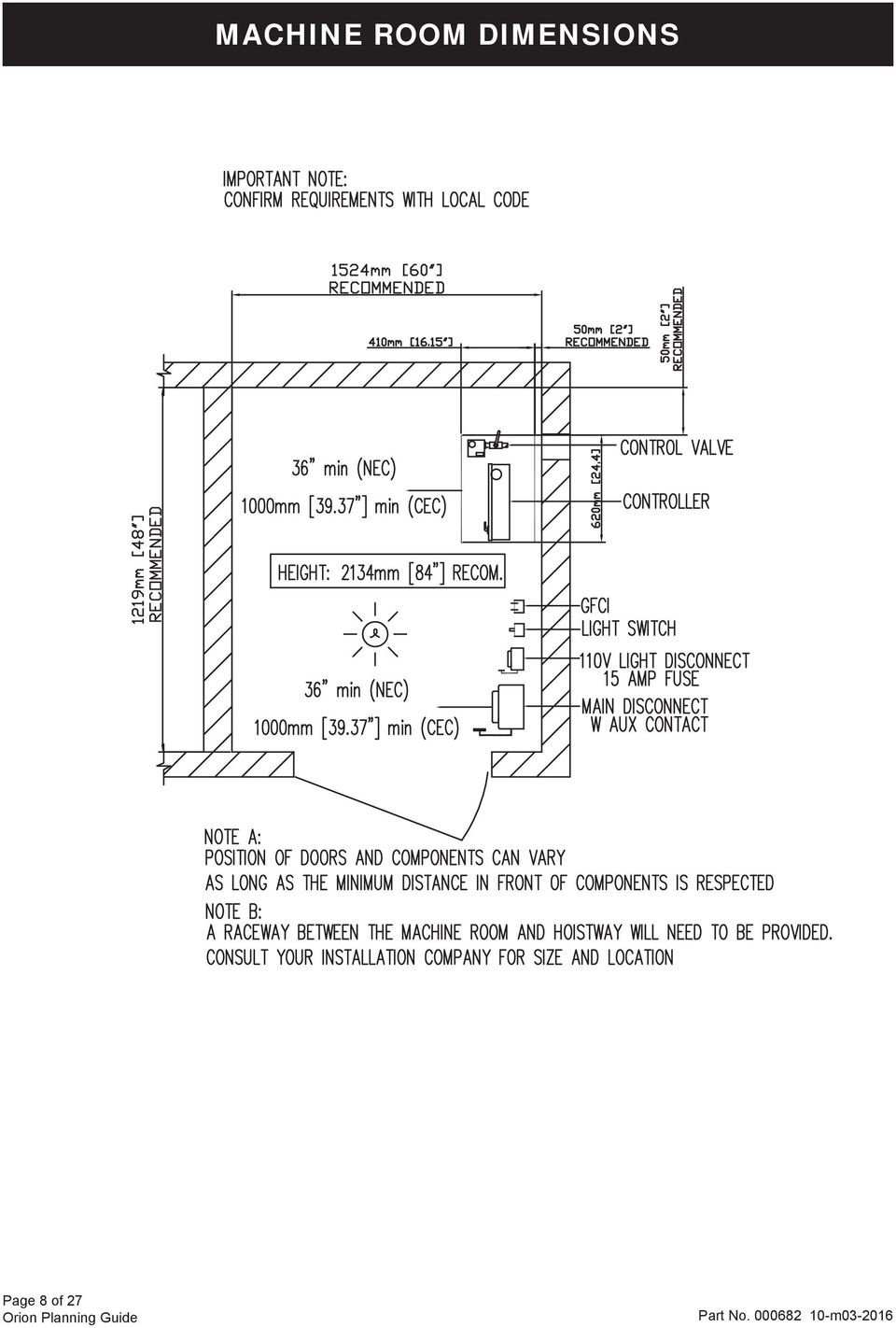
7 MACHINE ROOM OPTIONS 5 ft 0 in. min. 230/208 Disconnect 115 V Cab Lighting Disconnect Machine Room Light Switch GFI Duplex Wall Recetacle 5 ft 0 in. min. Left Hand Position Right Hand Position Back Position Remote Position o Machine room must be built in accordance with elevator manufacturer and applicable building codes and regulations. Adequate ventilation is required to maintain a temperature of 50 to 120 F for output of 3600 BTU per hour. o A convenience outlet of 115 VAC 15 Amp single-phase with G.F.I. shall be located next to the light switch in the machine room (provided and installed by others). o Provide lockable, in open position, fused disconnect switches located adjacent to the elevator controller. Fusing must be selectively coordinated. Fuse either 208V three-phase w/30 Amp or 240V single-phase w/40 Amp service; fuse 115V for 15 Amp service for cab lighting. (Must comply with applicable codes.) o The electrical circuit provided shall be either 30 Amp 208V three-phase or 40 Amp 240V single-phase, dedicated circuit with equipment ground. The circuit shall terminate on the line side terminal lugs of the disconnect. The electrical circuit is provided and installed by others. o Disconnect switch to have auxiliary normally open interlock switch. Interlock equal to Square D EK-300-Z. o 30 wide x 36 deep work space required in front of the disconnects and the elevator controller. o Machine room lighting shall be a minimum of 19 foot-candles (204 lux) at working surfaces. The switch for the light must be within 18 of the strike side of the machine room door. The light must be guarded to prevent accidental breakage or contact with the hot bulb. The switch, light, wiring, and guard are provided and installed by others. o A telephone line circuit is to be provided and installed by others. This circuit shall be brought to the machine room controller in conduit. This circuit must be connected to a dedicated outside line or a 24 hour central exchange. o The elevator controller/pump unit dimensions wide x 62.8 high x deep with 39 clear space in front. o Machine room access door must be self closing, self locking, key locked and have a spring return latch. o Consult local building codes for door construction. The door and hardware are both provided and installed by others. o Machine room is required to be free of all pipes, wiring and obstructions not related to the operation of the elevator. Provide a 4 inch conduit from the lift shaft to the remote machine room. Page 7 of 27

8 MACHINE ROOM DIMENSIONS Page 8 of 27
9 HOISTWAY AND PIT ELECTRICAL NOTES o A load bearing wall is required to sustain rail reactions. See page 18 for rail reactions. o Suggested hoistway pit fl oor construction consists of an 8 (203 mm) concrete slab poured on a natural or compacted soil with a minimum allowable bearing pressure of 1.0 KSF. o The minimum compressive strength of the concrete at 28 days must be no less than 3000 PSI. #5 reinforcing steel (grade 60) must be placed at the bottom of the slab in 2 traverse directions and at a spacing of 12 (305 mm). o Hoistway pit fl oor to support a load of 10 kips (10,000 lbs)/44.48kn (includes impact). o 120 (3048 mm) overhead clearance required above the top landing fl oor with top prop (existing construction). o 134 (3404 mm) overhead clearance required above the top landing fl oor without top prop (new construction). o 14 (356 mm) minimum pit. (A clearance device is provided to attain required 36 (914 mm) refuge space). o Hoistway sizes refl ect running and access clearances only. Consult your local AHJ to assure compliance with local codes. o Hoistway is required to be free of all pipes, wiring and obstructions not related to the operation of the elevator. o If a dedicated pit light is required by your local AHJ, please follow the guidelines below for accommodating this in your hoistway 8¼ 5 Approximate space available for a dedicated light with guard. We recommend mounting the light after the elevator doors have been installed to ensure adequate clearance. 15¾ 10 Type 1 Cab 5 GFI 9 The dedicated GFI outlet is approximately 24 up from the lower landing fi nished fl oor light switch mounted directly above. Type 2 Cab 9 Clear Distance (from inside fi nished surface of hoistway to edge of electrical box). 9 GFI Page 9 of 27
 must be placed at the bottom of the slab in 2 traverse directions and at a spacing of 12 (305 mm). o Hoistway pit fl oor to support a load of 10 kips (10,000 lbs)/44.")
10 CONTROLLER TANK SPECIFICATIONS Dimensions (inches) H 57 x W 28 x D 17 (approx.) Minimum Required Clearance in Front (inches) 39 Valve and Manual Lowering Handle Location Inside tank Rupture Valve Test T-fi tting factory installed Tank to Controller Wiring Quick connect valve and motor wiring Controller Layout PLC Keyed Lock to Tank Yes Machine Room Required Yes Tank Capacity (gal/ltr) gal/57-63 ltr Max. Dry Weight (lbs/kgs) 147 lbs/55 kg Max. Filled Weight (lbs/kgs) 312 lbs/117 kg Operating Environment 50 F - 80 F /10 C - 27 C Operating Volume 57 dba Controller Tank Features Hydraulic hose connection ports on either side of the tank Built in handles on either side of the tank Isolation mounting of pump motor valve assembly minimizes operating noise 36.40" 6.21" 20.39" " " Page 10 of 27 PLC Controller Tank
 312 lbs/117 kg Operating Environment 50 F - 80 F /10 C - 27 C Operating Volume 57 dba Controller Tank Features Hydraulic hose connection ports on either side of the tank Built")
11 ORION 48 X 54 TYPE 1 WITH 2 SPEED DOORS Type 1 Finished hoistway dimensions must include the drywall (where applicable). Determine the fi re rating of the hoistway, the type and layers of sheet rock. Build only from shop drawings specifi c to your project. For Metric Equivalents Multiply inches times 25.4 for mm Example: x 25.4 = mm Type 1-48 x 54 w/ 2 Speed Doors For Masonry or Drywall Entrance Details, refer to drawings on pages NOTE Plan view drawing can be reversed for Right Hand applications. The cab dimensions provided in this manual are based on a PLAM cab. Page 11 of 27

12 ORION 48 X 54 TYPE 2 WITH 2 SPEED DOORS Type 2 Finished hoistway dimensions must include the drywall (where applicable). Determine the fi re rating of the hoistway, the type and layers of sheet rock. Build only from shop drawings specifi c to your project. For Metric Equivalents Multiply inches times 25.4 for mm Example: x 25.4 = mm Type 2-48 x 54 w/ 2 Speed Doors For Masonry or Drywall Entrance Details, refer to drawings on pages NOTE The cab dimensions provided in this manual are based on a PLAM cab. Page 12 of 27

13 ORION 51 X 51 TYPE 3 (4) WITH 2 SPEED DOORS Type 3 or 4 Finished hoistway dimensions must include the drywall (where applicable). Determine the fi re rating of the hoistway, the type and layers of sheet rock. Build only from shop drawings specifi c to your project. For Metric Equivalents Multiply inches times 25.4 for mm Example: x 25.4 = mm Type 3 (4) 51 x 51 w/ 2 Speed Doors For Masonry or Drywall Entrance Details, refer to drawings on pages NOTE Plan view drawing can be reversed for Type 4 applications. The cab dimensions provided in this manual are based on a PLAM cab. Page 13 of 27
 51 x 51 w/ 2 Speed Doors For Masonry or Drywall Entrance Details, refer to drawings on pages 19-22 NOTE Plan view drawing can be")
14 ORION 42 X 60 TYPE 1 WITH 2 SPEED DOORS Type 1 Finished hoistway dimensions must include the drywall (where applicable). Determine the fi re rating of the hoistway, the type and layers of sheet rock. Build only from shop drawings specifi c to your project. For Metric Equivalents Multiply inches times 25.4 for mm Example: x 25.4 = mm Type 1-42 x 60 w/ 2 Speed Doors For Masonry or Drywall Entrance Details, refer to drawings on pages NOTE Plan view drawing can be reversed for Right Hand applications. The cab dimensions provided in this manual are based on a PLAM cab. Page 14 of 27

15 ORION 42 X 60 TYPE 2 WITH 2 SPEED DOORS Type 2 Finished hoistway dimensions must include the drywall (where applicable). Determine the fi re rating of the hoistway, the type and layers of sheet rock. Build only from shop drawings specifi c to your project. For Metric Equivalents Multiply inches times 25.4 for mm Example: x 25.4 = mm Type 2-42 x 60 w/ 2 Speed Doors For Masonry or Drywall Entrance Details, refer to drawings on pages NOTE The cab dimensions provided in this manual are based on a PLAM cab. Page 15 of 27

16 ORION 48 X 54 TYPE 1 WITH SWING DOORS Type 1 Finished hoistway dimensions must include the drywall (where applicable). Determine the fi re rating of the hoistway, the type and layers of sheet rock. Build only from shop drawings specifi c to your project. For Metric Equivalents Multiply inches times 25.4 for mm Example: x 25.4 = mm Type 1-48 x 54 w/ Swing Doors NOTE Plan view drawing can be reversed for Right Hand applications. The cab dimensions provided in this manual are based on a PLAM cab. Page 16 of 27

17 ORION 48 X 54 TYPE 2 WITH SWING DOORS Type 2 Finished hoistway dimensions must include the drywall (where applicable). Determine the fi re rating of the hoistway, the type and layers of sheet rock. Build only from shop drawings specifi c to your project. For Metric Equivalents Multiply inches times 25.4 for mm Example: x 25.4 = mm Type 2-48 x 54 w/ Swing Doors NOTE The cab dimensions provided in this manual are based on a PLAM cab. Page 17 of 27

18 LOADS ON BUILDING AND PIT LOADING Seismic zones 0 and 1 Seismic zone 2 Seismic zone 3 or greater 720 lbf 260 lbf 1200 lbf 300 lbf 2400 lbf 400 lbf Rail reactions do not include safety factors. Applicable safety factors must be considered in hoistway design. Rails Rail Bracket Dimensions Support Wall Orientation R3- Condition I: when fully loaded car hits buffer (bumper) R4 - Condition II: when safeties engage on rails with 110% loaded car at governor tripping speed R5 - Condition III: normal running with 1.2 times impact for starting and stopping jerks Page 18 of 27

19 ENTRANCE MOUNTING DETAILS FOR 2 SPEED DOORS WITH DRYWALL CONSTRUCTION Page 19 of 27

20 ENTRANCE MOUNTING DETAILS FOR 2 SPEED DOORS WITH DRYWALL CONSTRUCTION Contractor please note: Grouting at the sill may be required after the door frames are set. Page 20 of 27

21 ENTRANCE MOUNTING DETAILS FOR 2 SPEED DOORS WITH MASONRY CONSTRUCTION Page 21 of 27
22 ENTRANCE MOUNTING DETAILS FOR 2 SPEED DOORS WITH MASONRY CONSTRUCTION Contractor please note: Grouting at the sill may be required after the door frames are set. Page 22 of 27
23 2 SPEED AUTOMATIC DOOR AND GUIDE RAIL INFORMATION min. to 8 max. 80 Clear Inside 82 2 Spd Frame 88 Lintel Measured from Top of Finished Floor For Metric Equivalents Multiply inches times 25.4 for mm 2 Speed Door Rough Opening For Swing Doors the rough opening is 46 Wide Example: x 25.4 = mm Door Frame Elevation Notes: 1. See hoistway requirements for the location of the door centerline. 2. Door panels and frame are primed for painting. Rails ands Sling in Hoistway Page 23 of 27
24 PIT AND OVERHEAD CLEARANCE DETAILS 14 Pit Depth A minimum pit depth of 14 is required. 120 Overhead for Existing Constructions 134 Overhead for New Constructions Page 24 of 27
25 ORION STANDARD NOTES o o o o o o o o HOISTWAY The hoistway must be designed and built in accordance with the Safety Code for Elevators and Escalators (ASME A17.1) and all state and local codes. Due to close running clearances, the owner/agent must ensure that the hoistway and pit (where provided) are level, plumb and square and are in accordance with the dimensions on these drawings. MINIMUM OVERHEAD CLEARANCE Owner/agent must ensure the minimum overhead clearance is in compliance with codes. CONSTRUCTION SITE Owner/agent to provide all masonry, carpentry and drywall work as required and shall patch and make good (including fi nish painting) all areas where walls/fl oors may need to be cut, drilled or altered in any way to permit the proper installation of the lift. DIMENSIONS Contractor/customer to verify all dimensions and report any discrepancies to our offi ce immediately. STRUCTURAL Structural engineer to assure that the building and shaft will safely support all loads imposed by the lift equipment. Refer to the tables on the installation drawings for loads imposed by the equipment. Suitable lintels must be provided by the owner/agent. Door frames are not designed to support overhead wall loads. ELECTRICAL Power supply with a lockable fused disconnect and auxiliary contact to brake the battery feed, or circuit breakers with a 3-pole breaker for battery feed required in compliance with electrical code (contact your Savaria dealer or refer to the table below for OEM part numbers). Disconnect Switch Types & Accessories Cutler Hammer Federal Pioneer Siemens 1 PHASE 5 H.P. Pump Unit 2 Pole Solid Neutral 240V 1 PH 1HD222N 1622SN ID322 Required Auxiliary Contact DS16CP E1K-1AEV-W94 MSSAK 116 Required Type D Fuse (Buss type FRN or equal) 2@40 amp 2@40 amp 2@40 amp 3 PHASE 5 H.P. Pump Unit 3 Pole Solid Neutral 208V 3 PH 1HD321N 1332SN ID321 Required Auxiliary Contact DS16CP E1K-1AEV-W94 MSSAK 116 Required Type D Fuse (Buss type FRN or equal) 3@30 amp 3@30 amp 3@30 amp Cab Lighting 1 Pole Solid Neutral 120V 1 PH GP 111N CFN 211 Required Type D Fuse (Buss type T or equal) 1@15 amp 1@15 amp 1@15 amp o o o o Permanent power of 240V single-phase 40 Amp or 208V three-phase 30 Amp must be supplied by others before installation. Remote hall call (when supplied) to be installed by the owner/agent at 42 from the landing fl oor. ENTRANCES Entrance assemblies must be adjusted to align with the platform and interlock equipment. Others to allow an adequate rough opening. Entrance assembly must be securely fastened to walls by the elevator contractor. Page 25 of 27
26 SPECIFICATIONS FOR PART 5.3 COMPLIANCE PART 1 GENERAL 1.01 SUMMARY A. The product described herein, manufactured by Savaria is an elevator designed and dimensioned to provide Limited Use/Limited Application (LULA) elevator to suit individual building requirements for use by persons with disabilities. 1.2 REFERENCES A. Elevator shall be designed, manufactured and installed in accordance with the following standards: 1. American National Standards Institute (ANSI). 2. American Society of Mechanical Engineers (ASME). 3.National Electrical Code (NEC) Canadian Electrical Code (CEC) 4. American Society for Testing Materials (ASTM). 5. American Welding Society (AWS). Canadian Welding Bureau (CWB) 1.3 SYSTEM DESCRIPTION A. 5 hp submersed motor and pump with electronic proportional valve assembly; Programmable logic controller with collective operation; 1:2 roped hydraulic single stage cylinder with line rupture valve. B. Number of Stops: (specify:) Two to Four. C. Car Confi guration: (specify:) straight-thru, 90 side exit or enter/exit same side. D. Maximum Travel: (specify:) Up to 25 (7.62 m) E. Rated Load: (specify:) 1400 lbs. (635 kg) F. Rated Speed: 30 fpm (.15m/s) G. Car Size: x 54 (1219 mm x 1372 mm) platform (standard) (2134 mm) high ceiling H. Car Walls: (specify:) Steel panels (black or architectural white)with (optional) raised plastic laminate panels (contact Savaria for colors). I. Car Ceiling: White panel. J. Car Lighting: Four recessed lights. K. Operating Features: 1. Car Operating Panel: (specify:) Brushed stainless steel or brushed brass panel with illuminated automatic controls, keyed light switch, emergency stop switch and alarm button 2. Hall Stations: (specify:) Brushed stainless steel or brushed brass panel with illuminated button and (specify option:) key lock provided at each landing. 3. Car Door(s): Fully automatic, side opening, sliding car door with electromechanical interlocks, obstruction sensor, and automatic re-open system. 4. Hoistway Doors: 1 ½ hour fi re rated fully automatic side opening, sliding hoistway doors with two side opening panels in steel frame with electromechanical interlocks. 5. Handrail: (specify:) Stainless steel or brass. 6. Pit Switch 7. Car top inspection station with UP and DOWN test switches, emergency stop, light outlet 8. Automatic homing to the lowest fl oor (optional) 9. Slack rope safety. 10. Anti-creep device. 11. Overspeed governor (may not be required) consult AHJ 12. Dual direction leveling. Upper and lower terminal limit. Pump run timer. Pit clearance device (where required) Automatic battery powered and manual emergency lowering control devices. Minimum pressure switch. Maintenance stop blocks. (specify option:) Fire Fighters Service (available). (specify option:) Hall lanterns with chime. (specify option:) Recessed telephone cabinet (brushed stainless steel or brushed brass). (specify option:) Buffer springs (requires 24 pit). 1.4 QUALITY ASSURANCE A. Manufacturer: Provide elevator manufactured by a fi rm with a minimum of 10 years experience in fabrication of elevators equivalent to those specifi ed. B. All designs, clearances, workmanship and material, unless specifi cally accepted, shall be in accordance with all codes having legal jurisdiction. C. All load ratings and safety factors shall meet or exceed those specifi ed by all governing agencies with jurisdiction and shall be certifi ed by a professional engineer. D. Elevator shall be subject to applicable state, local and city approval prior to installation and subject to inspection after installation. Determination of and adherence to these regulations is the responsibility of the elevator contractor. E. Welders certifi ed in accordance with requirements of AWS D1.1 or CWB shall perform all welding of all parts. F. Substitutions: No substitutions permitted. 1.5 WARRANTY A. Warranty: Manufacturer shall warrant component parts of the Orion elevator for a period of 36 months from shipping date. This warranty only applies to products installed and maintained by a Savaria Authorized Dealer in conformance with all applicable local and national codes. The warranty is void if regular inspection and maintenance of product is not being carried out by an Authorized Savaria Dealer in accordance with the recommendations contained in the Owner s Manual. It is the Owner s responsibility to keep records of all such service. Page 26 of 27
27 PART 2 PRODUCT 2.1 MANUFACTURER Provide the Orion Commercial LU/LA Elevator manufactured by Savaria. Toll Free Number (800) Phone (905) Fax (905) Web site: MATERIAL Guide Rail: Dual 8 lbs./ft. machined steel T-rail system. Wire Rope: Two 3/8 diameter 7 x 19 ga. IWRC aircraft cables with rope wedge sockets. Sling: Structural and formed steel plates with guide shoes. Platform Floor: Unfi nished plywood fl ooring. 2.3 FINISHES A. Components shall be prepared with 1) pre-treatment, 2) alkaline detergent wash, 3) clear water rinse, 4) iron phosphate coating, 5) clear water rinse and fi nished with electrostatically applied and baked thermostatic powder coat fi nish. Standard color is architectural white. 3.2 EXAMINATION A. Use fi eld dimensions and approved manufacturer s shop drawings to examine substrates, supports and other conditions under which this work is to be performed. Do not proceed with work until unsatisfactory conditions are corrected. 3.3 INSTALLATION A. The Orion elevator shall be installed in accordance with manufacturer s instructions and as specifi ed and approved by architect. 3.4 DEMONSTRATION A. The elevator contractor shall make a fi nal check of the elevator s operation with the Owner or Owner s representative present prior to turning the elevator over for use. The elevator contractor shall determine that operating and safety devices are functioning properly. END OF SECTION Intent of specifi cation is to broadly outline equipment required but does not cover details of design and construction. Dimensions and specifi cations are subject to constant change and continually evolving codes and product applications. For additional technical information, contact Savaria at (800) or ELECTRICAL SYSTEMS A. The electrical contractors shall provide: V three phase 30 AMP 60 Hz or 230 V single phase 40 AMP 60 Hz source in the machine area with manually operated fused line disconnect VAC, single phase, 15 amp, 60 Hz, single phase power source with manually operated fused line disconnect for car lighting and a light outlet inside the hoistway. 3. Telephone circuit in the machine area. PART 3 EXECUTION 3.1 ACCEPTABLE INSTALLERS A. Installers shall be experienced in performing work of this section who have specialized in work comparable to that required for this project. B. Installers shall be certifi ed and trained by the manufacturer. Page 27 of 27
28 2 Walker Drive Brampton, ON Canada L6T 5E1 Phone: Fax: Sales:
Roped Hydraulic Residential Elevator Specifications
 January 1, 2004 Roped Hydraulic Residential Elevator Specifications P.O. Box 749, 5191 Stump Rd., Plumsteadville, PA 18949 Toll Free: 888-443-2800, Phone: 215-766-3380, Fax: 215-766-3385 CONTENTS Part
PUBLIC VERTICAL PLATFORM LIFT PLANNING GUIDE
 Multilift PUBLIC VERTICAL PLATFORM LIFT PLANNING GUIDE Applicable Codes: ASME A17.1 ASME A18.1 CSA B613 CSA B355-09 19-m01-2015 Part No. 000790 Copyright 2015 Savaria Corporation All rights reserved. Printed
V1504 Vertical Platform Lift OWNER S MANUAL
 V1504 Vertical Platform Lift OWNER S MANUAL (To Be Retained by Owner After Installation by Authorized Savaria Dealer) Part No. 000692 01-m03-2016 2 IMPORTANT Ensure that only an authorized Savaria Dealer
P.A.L. S SPECIFICATIONS
 PART 1- GENERAL 1.1 SCOPE To furnish all labor, materials and equipment necessary or required to complete the installation of the lift as indicated on the Drawings and Specifications. This specification
(B613) VERTICAL PLATFORM LIFT PLANNING GUIDE
 VERTICAL PLATFORM LIFT PLANNING GUIDE") Multilift (B613) VERTICAL PLATFORM LIFT PLANNING GUIDE Applicable Codes: CSA B613 01-m06-2011 Part No. 000790 Copyright 2011 Savaria Corporation All rights reserved. Printed in Canada Purpose of this guide
Multilift (B613) VERTICAL PLATFORM LIFT PLANNING GUIDE Applicable Codes: CSA B613 01-m06-2011 Part No. 000790 Copyright 2011 Savaria Corporation All rights reserved. Printed in Canada Purpose of this guide
V1504 Vertical Platform Lift OWNER S MANUAL
 V1504 Vertical Platform Lift OWNER S MANUAL (To Be Retained by Owner After Installation by Authorized Savaria Dealer) Part No. 000692 03-m12-2013 2 IMPORTANT Ensure that only an authorized Savaria Dealer
LOADING DOCK EQUIPMENT. A. Section 03100 - Concrete Forms and Accessories: Placement of anchors into concrete.
 LOADING DOCK EQUIPMENT PART 1 GENERAL 1.1 SECTION INCLUDES A. Loading dock equipment of the following types: 1. Dock lifts. 2. Control stations. 1.2 RELATED SECTIONS A. Section 03100 - Concrete Forms and
All work must conform to the National Electric Code, latest edition, and all other applicable codes and regulations.
 DIVISION 16 ELECTRICAL SECTION 16100 - ELECTRICAL PART 1 - GENERAL SCOPE All electrical work as shown on the drawings and as necessary to provide a complete electrical system. Include primary service,
SECTION 14 20 10 - FREIGHT & PARKING GARAGE ELEVATORS PART I - GENERAL
 SECTION 14 20 10 - FREIGHT & PARKING GARAGE PART I - GENERAL 1.1 SECTION INCLUDES [NOTE to AE: The following lists requirements that are specific to freight elevators. These requirements are in addition
Pump Specifications 250 Series Submersible Sump / Effluent Pump 2 Solids handling
 Pump Specifications 250 Series Submersible Sump / Effluent Pump 2 Solids handling 250_P1 R10/7/2015 Copyright 2015 Liberty Pumps Inc. All rights reserved. Specifications subject to change without notice.
ITEM DESCRIPTION SPECIFICATION TENDER OFFER
 TECHNICAL SPECIFICATIONS PL1 & PL2 PLEASE TICK IF YOU COMPLY. SPECIFY YOUR OPTION IF YOU DON'T. ITEM DESCRIPTION SPECIFICATION TENDER OFFER Make (please specify) 1.0 Type Duplex Passenger Lift 2.0 Minimum
CITY AND COUNTY OF DENVER POLICY DENVER FIRE DEPARTMENT SUBMITTAL OF CONVEYANCE INSTALLATION/ALTERATION PLANS
 Subject: SUBMITTAL OF CONVEYANCE INSTALLATION/ALTERATION PLANS Reference: Denver Fire Code Section 105.7.29 Approved: Joseph L. Gonzales, Division Chief, Fire Prevention Division Number: 105-1 Effective
SECTION 08360 SECTIONAL OVERHEAD DOORS 521 SERIES ALUMINUM SECTIONAL OVERHEAD DOORS
 SECTION 08360 SECTIONAL OVERHEAD DOORS 521 SERIES ALUMINUM SECTIONAL OVERHEAD DOORS Display hidden notes to specifier by using Tools / Options / View / Hidden Text. On newer versions of Microsoft Word
SECTION 08332 COILING COUNTER DOORS. Display hidden notes to specifier. (Don't know how? Click Here)
") SECTION 08332 COILING COUNTER DOORS Display hidden notes to specifier. (Don't know how? Click Here) PART 1 GENERAL 1.1 SECTION INCLUDES A. Coiling Metal Counter Doors. B. Coiling Counter Fire Doors. 1.2
SECTION 08332 COILING COUNTER DOORS Display hidden notes to specifier. (Don't know how? Click Here) PART 1 GENERAL 1.1 SECTION INCLUDES A. Coiling Metal Counter Doors. B. Coiling Counter Fire Doors. 1.2
Machine Room Less (MRL) Elevators. Evolution in elevator design.
 Elevators. Evolution in elevator design.") Machine Room Less (MRL) Elevators. Evolution in elevator design. By: Bill Glas, Product Manager, Schindler Elevator Corporation Machine Room Less (MRL) elevators are an emerging yet proven technology and
Machine Room Less (MRL) Elevators. Evolution in elevator design. By: Bill Glas, Product Manager, Schindler Elevator Corporation Machine Room Less (MRL) elevators are an emerging yet proven technology and
IRRIGATION PUMPING Table of Contents - Section 900
 IRRIGATION PUMPING Table of Contents - Section 900 PARAGRAPH 900.1 GENERAL 1 900.2 METERING REQUIREMENTS 1 900.3 CUSTOMER S CONTROL EQUIPMENT 2 900.4 SERVICE CONDUCTOR REQUIREMENTS 2 900.5 RECOMMENDATIONS
Utility Distribution Systems
 Utility Distribution Systems 6/2012 A0011037 1 WARRANTY This equipment is warranted to be free from defects in materials and workmanship, under normal use and service, for a period of 12 months from date
26 3213.13 Diesel Engine Driven Generators Page 1 of 6
 Last Update: December 8, 2014 A. Description of System Consultant s Handbook Page 1 of 6 1. Provide a diesel engine driven electric generating unit, factory assembled, tested and certified to operate at
CLEAR-DIVISIONS CENTERFOLD
 CLEAR-DIVISIONS CENTERFOLD Introduction: The following three (3) part specification offers the Standard and Optional features for the CLEAR-DIVISIONS CENTERFOLD moveable The yellow highlighted areas in
Contractors Guide Central Inverter System Installation
 Contractors Guide Central Inverter System Installation Step By Step Procedures 2,200 Watt/VA 6 Step Installation 1. Mount Bottom Cabinet 2. Mount Top Cabinet 3. Install Batteries 4. Install Conduit 5.
MODEL 300505 INSTALLATION INSTRUCTIONS
 WWW.BURCAM.COM 2190 Boul. Dagenais West TEL: 514.337.4415 LAVAL (QUEBEC) FAX: 514.337.4029 CANADA H7L 5X9 [email protected] Your pump has been carefully packaged at the factory to prevent damage during shipping.
METER REQUIREMENTS GENERAL REQUIREMENTS SECTION D
 12 - ELECTRIC SERVICE HANDBOOK SECTION D METER REQUIREMENTS This chapter gives you information on Central Lincoln s metering requirements. It's divided into three sections: General requirements This section
BUILT-IN DISHWASHER INSTALLATION INSTRUCTIONS
 BUILT-IN DISHWASHER INSTALLATION INSTRUCTIONS PLEASE READ COMPLETE INSTRUCTIONS BEFORE YOU BEGIN LEAVE INSTALLATION INSTRUCTIONS AND USER'S GUIDE WITH OWNER ALL ELECTRIC WIRING AND PLUMBING MUST BE DONE
2. Division 05 Structural Steel Framing for steel framework requirements
 SECTION 131200 - CLIMBING WALLS PART 1 GENERAL 1.1 SUMMARY A. This section includes the following: 1. GFRC Rock Realistic Climbing Wall System B. Related Sections 1. Division 04 Unit Masonry 2. Division
Planning Information. Passenger and Freight Elevators.
 A company of ThyssenKrupp Elevator Thyssen Aufzüge tk This planning information will give you an overview of the most important planning criteria of passenger and freight elevators. However you should
ELECTRICAL CONTRACTORS THE UNIVERSITY OF TENNESSEE KNOXVILLE, TENNESSEE SECTION 16050 PAGE 1
 KNOXVILLE, TENNESSEE SECTION 16050 PAGE 1 PART 1 - GENERAL 1.01 RELATED DOCUMENTS: SECTION 16050 A. Drawings and general provisions of Contract, including General and Supplementary Conditions and Division-1
DEPARTMENT OF CORRECTIONS
 Elevator Consulting, LLC. Post Office Box 464 Mequon, WI 53092-0464 Voice/Fax: 262-242-3077 Mobile No: 262-853-1054 E-mail: [email protected] DEPARTMENT OF CORRECTIONS MILWAUKEE SECURE DETENTION
SECTION 10680 MediaStation Model 125 Electric Lateral Files (ELF)
") SECTION 10680 MediaStation Model 125 Electric Lateral Files (ELF) PART 1-GENERAL 1.01 RELATED WORK SPECIFIED IN OTHER SECTIONS A. Electrical connections see electrical specifications. 1.02 SUBMITTALS A.
SECTION 10680 MediaStation Model 125 Electric Lateral Files (ELF) PART 1-GENERAL 1.01 RELATED WORK SPECIFIED IN OTHER SECTIONS A. Electrical connections see electrical specifications. 1.02 SUBMITTALS A.
Fire Pump Plan Review March 2010
 Fire Pump Plan Review March 2010 Date of Review: / / Permit Number: Business/Building Name: Address of Project: Designer Name: Designer s Phone: Contractor: Contractor s Phone: Occupancy Classification:
MOBILE FIRE - RESCUE DEPARTMENT FIRE CODE ADMINISTRATION
 MOBILE FIRE - RESCUE DEPARTMENT FIRE CODE ADMINISTRATION Fire Pump Plan Review 2009 International Fire Code and NFPA 20 Date of Review / / BLD201 - Project Address: Project Name: Contractor s Business
CCU Engineering Specifications. Section 003300 PRECAST CONCRETE PRODUCTS
 CCU Engineering Specifications Section 003300 Effective Date: Nov. 1st, 2011 Page 1 of 5 PRECAST CONCRETE PRODUCTS PART 1 - GENERAL The following specification is intended for use for the design, selection
301.7D. Mini Hydraulic Excavator
 301.7D Mini Hydraulic Excavator Engine Weights Gross Power (ISO 14396) 17.9 kw 24.3 hp Operating Weight with Canopy 1610 kg 3,550 lb Net Power 13.2 kw 17.7 hp Operating Weight with Cab 1720 kg 3,792 lb
SECTION 1 GENERAL REQUIREMENTS
 Page 1 of 6 SECTION 1 GENERAL REQUIREMENTS 1. SCOPE OF WORK: The work to be performed under the provisions of these documents and the contract based thereon includes furnishing all labor, equipment, materials,
freight elevators 2008 planning guide ThyssenKrupp Elevator Americas Business Unit
 freight elevators 2008 planning guide ThyssenKrupp Elevator mericas usiness Unit TK Our ommitment To You ependable. Tough. Efficient. The qualities you need in your freight elevators are the qualities
DESIGN CLARIFICATION (DC)
") DESIGN CLARIFICATION (DC) Owner: Victor Valley Wastewater Reclamation Authority Date: 03/03/2015 Contractor: W M Lyles Carollo Project No.: 8299A.20 Project Name: Subregional WRPs DC No.: 001 DC Title:
DESIGN CLARIFICATION (DC) Owner: Victor Valley Wastewater Reclamation Authority Date: 03/03/2015 Contractor: W M Lyles Carollo Project No.: 8299A.20 Project Name: Subregional WRPs DC No.: 001 DC Title:
CLEAR-DIVISIONS VARIOFOLD
 CLEAR-DIVISIONS VARIOFOLD Introduction: The following three (3) part specification offers the Standard and Optional features for the CLEAR-DIVISIONS VARIOFOLD moveable The yellow highlighted areas in the
Pump Specifications 405 Series Commercial Drain Pump (High-Temp) 2 Solids handling
 2 Solids handling") Pump Specifications 405 Series Commercial Drain Pump (High-Temp) 2 Solids handling 405_P1 R1/27/2012 Copyright 2012 Liberty Pumps Inc. All rights reserved. Specifications subject to change without notice.
Pump Specifications 405 Series Commercial Drain Pump (High-Temp) 2 Solids handling 405_P1 R1/27/2012 Copyright 2012 Liberty Pumps Inc. All rights reserved. Specifications subject to change without notice.
Select Radiators Installation Guide
 Select Radiators Installation Guide Table of Contents Informational Symbols...3 Before You Begin...4 Select Rough-In... 5 Connection Installation...6 Optional Piping Arrangements...7 Conventional Wall
Sports and High Mast Lighting Poles Phone: (866) 474-7200 Fax: (817) 924-7049
 474-7200 Fax: (817) 924-7049") Sports and High Mast Lighting Poles 4 High Mast Lighting Poles General American LitePole offers a raising and lowering system that allows for ease of maintaining the lighting system at ground level. Ideal
Sports and High Mast Lighting Poles 4 High Mast Lighting Poles General American LitePole offers a raising and lowering system that allows for ease of maintaining the lighting system at ground level. Ideal
Electrical for Detached Garages: Updated Feb 19, 2016 for 2015 CE Code in force Jan. 1, 2016. Underground branch circuit feeding a detached garage:
 Electrical for Detached Garages: Updated Feb 19, 2016 for 2015 CE Code in force Jan. 1, 2016 * Garage construction requires permits (electrical, building) * Permits must be applied for at the time. * Dial
Recommended Product Specifications Fuel Day Tank System Tramont UTRS Fuel Day Tank
 Recommended Product Specifications Fuel Day Tank System Tramont UTRS Fuel Day Tank This specification describes requirements for a Diesel Fuel Day Tank System consisting of one or more fuel tanks, an Electronic
Procurement Specification for a High Security Lift Arm Barrier (HSLAB) EB950 CR Armstrong High Security Lift Arm Barrier
 EB950 CR Armstrong High Security Lift Arm Barrier") Procurement Specification for a High Security Lift Arm Barrier (HSLAB) EB950 CR Armstrong High Security Lift Arm Barrier A. Requirement This document is to be used to specify the physical and operational
Procurement Specification for a High Security Lift Arm Barrier (HSLAB) EB950 CR Armstrong High Security Lift Arm Barrier A. Requirement This document is to be used to specify the physical and operational
CLEAR-DIVISIONS APERTO
 CLEAR-DIVISIONS Introduction: The following three (3) part specification offers the Standard and Optional features for the CLEAR-DIVISIONS moveable glass wall system. The yellow highlighted areas in the
BLADDER SURGE CONTROL SYSTEM
 PART I GENERAL 1.01 Description BLADDER SURGE CONTROL SYSTEM This specification describes the requirements for a Bladder Surge Control System. The purpose of the system is to minimize transient pressures
Automatic Door Openers and ADA Devices Rev. 0 Bid # 48240056. Scope of Work
 Scope of Work I. Scope of Solicitation II. Instructions to Offerors III. Scope of Work / Specifications IV. Terms and Conditions - Special I. SCOPE OF SOLICITATION Clemson is seeking to initiate a turnkey
Phoenix-3W Series One-Way Security Revolving Doors
 Phoenix-3W Series One-Way Security Revolving Doors ONE-WAY SECURITY REVOLVING DOOR SPECIFICATIONS ARCHITECTURAL SPECIFICATIONS Phoenix-3W Series One-Way Security Revolving Door Division 8 Doors and Windows
Magnum Mobile Generator MMG55 Specifications
 Empowering Real People Magnum Mobile Generator MMG55 Specifications ENGINE John Deere PE5030TF270 - turbocharged, diesel engine o Prime - 72 hp @ 1800 rpm o Standby - 80 hp @ 1800 rpm o 4 cylinder o 3.0
MODEL HSR-007 Direct Drive Rolling Steel
 MODEL HSR-007 Direct Drive Rolling Steel 200 Fairview Road, Unit #2, Barrie, Ontario L4N 8Z8 Tel: 866-792-9968 or 705-792-9968 Fax: 705-735-9564 www.tnrdoors.com email: [email protected] Model HSR-007
INSTRUCTIONS FOR COORDINATION SECTION 06651 SOLID SURFACE FABRICATIONS
 INSTRUCTIONS FOR COORDINATION SECTION 06651 SOLID SURFACE FABRICATIONS 1. Paragraph 1.02 Provide solid surface countertops at sinks locations. Provide solid surface window sills at drywall framing walls.
PLEASE NOTE. For more information concerning the history of these regulations, please see the Table of Regulations.
 PLEASE NOTE This document, prepared by the Legislative Counsel Office, is an office consolidation of this regulation, current to August 1, 2013. It is intended for information and reference purposes only.
-1- SPECIFICATIONS 002085 CONE SETTER PLATFORM ATTACHMENT INDEX
 -1-002085 CONE SETTER PLATFORM ATTACHMENT INDEX I. GENERAL EQUIPMENT : A. Intent Statement B. Cone Setter Platform II. III. 1. Understructure Frame 2. Mounting Components 3. Paint 4. Basket 5. Labels 6.
Electrical. This section applies to the design and installation of building power distribution systems.
 Basis of Design This section applies to the design and installation of building power distribution systems. Design Criteria This section contains the architectural, structural and mechanical provisions
SECTION 08 5656 GUARDA SECURITY WINDOW SCREENS
 Page 1 of 5 SECTION 08 5656 GUARDA SECURITY WINDOW SCREENS Guarda Security Window Screens in this specification are appropriate for use in windows, storefronts, curtain walls, vents, and any other applications
Automatic Door Selection Guide
 Automatic Door Selection Guide AAADM 1300 Sumner Avenue Cleveland, OH 44115 P: 216-241-7333 F: 216-241-0105 [email protected] Automatic Door Selection Guide General: The members of AAADM manufacture an assortment
SWIMMING POOL, SPA, & HOT TUB GUIDELINES
 SWIMMING POOL, SPA, & HOT TUB GUIDELINES Pool permit cost is based on the total value of the project. See Permit Fee Schedule Table 1A. A. Adopted construction codes and installation requirements 1. 2015
MISCELLANEOUS ELECTRICAL JOBS REQUIRING PERMITS
 MISCELLANEOUS ELECTRICAL JOBS REQUIRING PERMITS 01. SAFETY INSPECTION of service equipment at FPL Power Source 02. Construction GFI power outlets (Temp Pole for Construction) 03. 90 day temporary power
SPECIFICATIONS FOR THE INSTALLATION OF FIRE ALARM SYSTEMS, SPRINKLER SYSTEMS, AND MASTER BOXES IN THE POQUONNOCK BRIDGE FIRE DISTRICT
 SPECIFICATIONS FOR THE INSTALLATION OF FIRE ALARM SYSTEMS, SPRINKLER SYSTEMS, AND MASTER BOXES IN THE POQUONNOCK BRIDGE FIRE DISTRICT The purpose of these specifications is to insure that there are minimum
SPECIFICATIONS FOR TENDER NO: PSNR/SCP/VKS/E 1635 ANNEXURE I TECHNICAL SPECIFICATIONS FOR LIGHTING HIGH MAST
 TECHNICAL SPECIFICATIONS FOR LIGHTING HIGH MAST ANNEXURE I Sl.No. Description for BHEL Requirement Offered Deviation Scope of supply, erection and commissioning: 1 The scope of this specification covers
SECTION 15410 GROUND WATER STORAGE TANKS
 SECTION 15410 GROUND WATER STORAGE TANKS PART 1 GENERAL.01 SCOPE A. Section Includes Requirements for designing, fabricating, and erecting a welded steel ground storage tank..02 SYSTEM DESCRIPTION A. Design
ATS Overhead Table Shelf System INSTRUCTION MANUAL
 ATS Overhead Table Shelf System INSTRUCTION MANUAL ATS Overhead Table Shelf System Instruction Manual Warranty Newport Corporation warrants this product to be free of defects in material and workmanship
MANAGEMENT SOLUTION (P.A.M.S.)
") DOORKING SYSTEMS ACCESS CONTROL SOLUTIONS PERIMETER ACCESS MANAGEMENT SOLUTION (P.A.M.S.) Revision N, updated 01.12 PERIMETER ACCESS MANAGEMENT SOLUTION (P.A.M.S.) Design Concept How the System Works TYPICAL
DOORKING SYSTEMS ACCESS CONTROL SOLUTIONS PERIMETER ACCESS MANAGEMENT SOLUTION (P.A.M.S.) Revision N, updated 01.12 PERIMETER ACCESS MANAGEMENT SOLUTION (P.A.M.S.) Design Concept How the System Works TYPICAL
BUILDING PERMIT SPECIFICATIONS
 BUILDING PERMIT SPECIFICATIONS The below noted requirements are based upon La Plata County Building Code. These specifications are not intended as a complete set of requirements, but are intended to provide
MA BUILDING CODES ON SWIMMING POOLS SECTION 780 CMR 120.M
 MA BUILDING CODES ON SWIMMING POOLS SECTION 780 CMR 120.M APPENDIX 120.M SWIMMING POOLS, SPAS AND HOT TUBS SECTION 120.M101 GENERAL 120.M101.1 General. The provisions of this appendix shall control the
Doc Ref: 2015.06.01.002. 602.783.1112 baselayer.com 2015 BASELAYER TECHNOLOGY, LLC
 TM 602.783.1112 baselayer.com 2015 BASELAYER TECHNOLOGY, LLC TM D400E Data Module (60Hz) The EDGE D400E is designed to meet high power density requirements for both the HPC and Web Scale environments while
FIRE ALARM AND DETECTION SYSTEMS SECTION 16721
 PART 1 - GENERAL 1.01 WORK INCLUDED FIRE ALARM AND DETECTION SYSTEMS SECTION 16721 A. Provide a complete fully addressable, power limited, fire detection and evacuation system. The system shall be connected
Lift and Escalator Installations
 Buildings Department Practice Note for Authorized Persons, Registered Structural Engineers and Registered Geotechnical Engineers APP-29 Lift and Escalator Installations Building Works Requirements The
SECTION 15076 CEMENT-MORTAR LINED AND COATED STEEL PIPE
 SECTION 15076 CEMENT-MORTAR LINED AND COATED (CML&C) STEEL PIPE PART 1 GENERAL 1.01 DESCRIPTION This section designates the requirements for steel pipe fabrication, test in shop, installation of steel
Oil and Coolant Circulating Heating System. Model - OCSM
 Oil and Coolant Circulating Heating System Model - OCSM Installation & Operation Manual 216280-000 REV 2 Identifying Your System The HOTSTART heating system is designed to heat fluids for use in marine
CEILING CASSETTE FAN COIL UNIT
 CEILING CASSETTE FAN COIL UNIT Operation and Installation Manual MHCFC4W-04, 08, 12, 16 Four way ceiling cassette fan coil unit Please read this manual before using the fan coil unit. Installation and
S WORK CATALOGUE FAA29100H_BWC
 MACHINE ABOVE - 2, m/s BUILDER S WORK CATALOGUE FAA29100H_BWC 07-04-15 Version: a-e 800 kg 0 kg Otis Elevator Company 2007, All rights reserved MAIN 2/38 This catalogue summarizes useful information for
American Fireglass Outdoor Fire pit kit information. General instructions/warnings for outdoor gas pan and burner systems
 American Fireglass Outdoor Fire pit kit information General instructions/warnings for outdoor gas pan and burner systems We strongly recommend that our burner products be installed by a licensed and certified
Cardok Sàrl CP37 CH-1295 Tannay Switzerland Phone: 0041 22 77 66 051 [email protected]
 CARDOK CARLIFT Fast access to underground garages Fast, Silent, Discreet, Design, High-Tech Installation to replace an access ramp on private property Dimensions: (Built to measure, all dimensions can
Andersen Electric Window Opener for Andersen Awning and Roof Windows
 W A Electric Window Opener Electric Window Opener for Awning and Roof Windows Congratulations! You have just purchased one of the many fine products. For ease of installation and continued enjoyment of
SECTION 02845 GUARDRAILS
 SECTION 02845 GUARDRAILS PART 1 - GENERAL 1.01 SCOPE OF WORK A. Furnish all labor, materials, equipment and incidentals necessary and repair, replace or install all types of guardrails as specified herein
Morgue refrigeration unit
 Morgue refrigeration unit The Morgue refrigeration units are made of sturdy, self-supporting walls, floor and ceiling elements. They are delivered in separate components and are to be assembled on site
Mechanical Installation
 Page -1-1. INTRODUCTION AND PURPOSE 1.1. This specification covers the installation, testing and precommissioning of mechanical equipment. Work is to be performed in conjunction with the manufacturer s
AutoLink Three-Phase Sectionalizer Specifications. Scope. General. Applicable Standards. Operating principle
 Scope This specification stipulates the minimum requirements for mechanically linked three-phase electronic sectionalizers, for use on outdoor medium voltage overhead lines of 15, 27, and 38 kv. Electronic
CONSOLIDATED EDISON CO. OF NEW YORK, INC. 4 IRVING PLACE NEW YORK, NY 10003 DISTRIBUTION ENGINEERING DEPARTMENT SUBSTATION & EQUIPMENT SECTION
 CONSOLIDATED EDISON CO. OF NEW YORK, INC. 4 IRVING PLACE NEW YORK, NY 10003 DISTRIBUTION ENGINEERING DEPARTMENT SUBSTATION & EQUIPMENT SECTION SPECIFICATION EO-5023 REVISION 3 MARCH 2003 REQUIREMENTS FOR
PUBLIC RESTROOMS, DESIGN INTENT
 PUBLIC RESTROOMS, DESIGN INTENT 1.01 STRUCTURAL A. Where feasible, metal stud partitions will be constructed on a 6 high concrete curb. 1.02 MECHANICAL A. Restrooms will have a minimum of 15 air changes
Our professional elevator support staff and emergency elevator repair technicians are available to serve you 24 hours a day, seven days a week.
 Applied Elevator Service, Sales and Installation Applied Elevator delivers unparalleled customer service, proactive maintenance programs and dependability that will exceed your expectations. With more
Installation Manual. Toilet Partitions, Dressing Compartments & Shower Stalls
 Installation Manual Toilet Partitions, Dressing Compartments & Shower Stalls Metpar Corp 95 State Street, Westbury, New York, USA, 11590 Tel: 516-333-2600 Fax: 516-333-2618 Internet: http://www.metpar.com
Introduction. Safety Guidelines. Part Numbers. Operation and Maintenance Manual. Operation and Maintenance Manual
 Operation and Maintenance Manual Introduction Read all instructions thoroughly. Installation of the OilTector must comply with all Federal, State and Local Codes, Regulations and Practices. The OilTector
2a. IEM Indoor Metal Clad Medium Voltage Switchgear 15KV 16346-1. 2a. Section 16346 INDOOR METAL CLAD MEDIUM VOLTAGE SWTICHGEAR (Std.
 2a. IEM Indoor Metal Clad Medium Voltage Switchgear 15KV 16346-1 2a. Section 16346 INDOOR METAL CLAD MEDIUM VOLTAGE SWTICHGEAR (Std. Relays) Part 1 General 1.1 CONDITIONS AND REQUIREMENTS: A. Refer to
Commercial Electric Water Heater
 MODEL SE Commercial Electric Water Heater 6-120 Gallon Capacity, up to 58 KW in all Three Phase Voltages, Over 6 KW in all Single Phase Voltages Features Heavy Duty Construction Hydrastone cement lining
Commercial Gas Furnace Upflow
 Commercial Gas Furnace Upflow Model G24-200 80% A.F.U.E. 200,000 Btuh Input Heating Cap. 7.5 or 10 Tons Nominal Add-On Cooling GUK FEATURES Certified by A.G.A./C.G.A. Laboratories. Heavy gauge painted
Light Duty Commercial Electric Water Heater
 Features Heavy Duty Construction Hydrastone cement lining provides longer tank life Copper-silicon tappings cannot rust or corrode High impact composite jacket eliminates damage during installation and
REFRIGERATION. Standard Features & Accessories. Model Options. Built-In 30 W. Full-Height Wine Cellar. All models include. VCWB300 Professional
 Standard Features & Accessories All models include Capacity accommodates up to 150 full-size bottles o 84 H./24 D. Exclusive TriTemp storage system o Three independent temperature zones o Settings are
Mobile Home Pre-Inspection Checklist
 Mobile Home Pre-Inspection Checklist TWO (2) STEP INSPECTION PROCESS STEP ONE: CALL FOR THE FIRST INSPECTION WHEN THESE ITEMS ARE COMPLETE. 1. Septic tank installed and plumbing complete. (SEE PLUMBING
HEAT WAVE DUCT KIT KIT # 946-568
 HEAT WAVE DUCT KIT KIT # 946-568 www.regency-fire.com Approved for use with Models: P36, P36D, P42, P48, P90, P95, L676S, P33S & HZ54 WARNING: Improper installation, adjustment, alteration, service or
Single Family Residential Basement Finish
 How to Use This Guide Building Guide Pottawattamie County Planning & Development Department Building & Safety Division Single Family Residential Basement Finish Provide two (2) sets of plans and complete
Line to Refrigerator Ice/Water Dispenser
 Standard 18 Line to Refrigerator Ice/Water Dispenser Pump Module Bottled Water How The System Works The FLOJET Bottled Water Dispensing System was designed to pump water from a commercially available 5-gallon
OWNER S MANUAL FORCE 10 MARINE COMPANY 23080 HAMILTON ROAD RICHMOND, BC CANADA V6V 1C9 TEL: (604) 522-0233 FAX: (604) 522-9608
 522-0233 FAX: (604) 522-9608") Electric Water Heater OWNER S MANUAL FORCE 10 MARINE COMPANY 23080 HAMILTON ROAD RICHMOND, BC CANADA V6V 1C9 TEL: (604) 522-0233 FAX: (604) 522-9608 If your water Heater is Damaged or you have questions
Electric Water Heater OWNER S MANUAL FORCE 10 MARINE COMPANY 23080 HAMILTON ROAD RICHMOND, BC CANADA V6V 1C9 TEL: (604) 522-0233 FAX: (604) 522-9608 If your water Heater is Damaged or you have questions
ELECTRIC METERING COMMERCIAL & INDUSTRIAL
 ELECTRIC METERING COMMERCIAL & 1.0 INDEX 1.0 INDEX 2.0 SCOPE 3.0 GENERAL REQUIREMENTS 4.0 METER LOCATIONS 5.0 UNDERGROUND TERMINATIONS 6.0 METERING TRANSFORMER ENCLOSURES 7.0 SINGLE CUSTOMER METER INSTALLATIONS
Security Systems Intrusion Alarm
 Dufferin-Peel Catholic District School Board STANDARD TEXT GUIDELINE FOR Security Systems for SECONDARY AND ELEMENTARY SCHOOLS Prepared by the Plant Department With Assistance from Vision Dynamics Formatted
NO-TOUCH WASHROOM ACCESSORIES. ASI is the Solution to Making Your Bathrooms Better
 NO-TOUCH WASHROOM ACCESSORIES ASI is the Solution to Making Your Bathrooms Better Multiple Models and Finishes More choices Sanitary All are no-touch operation Easy Installation Installs quickly with standard
Sapa: SECTION 05520 ARCHITECTURAL ALUMINUM HANDRAILS AND RAILINGS
 PART 1 GENERAL Sapa: SECTION 05520 ARCHITECTURAL ALUMINUM HANDRAILS AND RAILINGS 1.1 SECTION INCLUDES A. Aluminum and Glass Handrails B. Aluminum Railings 1.2 RELATED SECTIONS A. Section 05700 - Ornamental
09/07/07 GLASSFIBER REINFORCED CEMENT (GRC) C. S. I. Spec 03500 Master Spec. 03 49 00 Page 1
 C. S. I. Spec 03500 Master Spec. 03 49 00 Page 1") C. S. I. Spec 03500 Page 1 PART 1 - GENERAL 1.01 SUMMARY:.01 Provide special glassfiber reinforced cement (GRC) shapes in accordance with the requirements of the contract documents..02 The installing contractor
C. S. I. Spec 03500 Page 1 PART 1 - GENERAL 1.01 SUMMARY:.01 Provide special glassfiber reinforced cement (GRC) shapes in accordance with the requirements of the contract documents..02 The installing contractor
8146/5 Series Breaker Panelboards
 8146/5 Series Breaker Panelboards DISTRIBUTION BREAKER PANELBOARDS FOR HAZARDOUS & CORROSIVE ENVIRONMENTS Breaker Panels Features: Wide variety of Flameproof branch circuit breakers for Zone 1 & Division
Generator DoCKInG StatIonS
 Generator DOCKING STATIONS TRYSTAR Portable Power Cable Cam to cam cable extensions 2000V, 100A-400A rated to NEC table 400.5 (B) All portable power cable sold is highly flexible and UL & C-UL or CSA Listed