Wisconsin Building Products Evaluation
|
|
|
- Amos Parrish
- 9 years ago
- Views:
Transcription
1 Safety & Buildings Division 201 West Washington Avenue P.O. Box 2658 Madison, WI Evaluation # O Wisconsin Building Products Evaluation Material Best Management Standards for Foundation Repair Manufacturer Wisconsin Association of Foundation Repair Professionals (WAFRP) SCOPE OF EVALUATION GENERAL: This report evaluates the Best Management Standards for Foundation Repair for compliance with the requirements of the current edition of the Wisconsin Uniform Dwelling Code for 1- and 2-family dwellings and the current edition of the Wisconsin Enrolled Commercial Building Code. The Standards were prepared specifically for the Wisconsin Association of Foundation Repair Professionals (WAFRP) in cooperation with the Building Inspectors Association of Southeastern Wisconsin to address various conditions and foundation repair standards. The Comm requirements below in accordance with the current Wisconsin Uniform Dwelling Code for 1- and 2-family dwellings: Soil Lateral Loads: The engineered foundation products were evaluated in accordance with the foundation requirements of s. Comm 21.18(1)(c). Masonry Foundation Walls: The engineered foundation products were evaluated in accordance with the structural requirements of s. Comm 21.18(3)(b). Floor Design: The engineered foundation products were evaluated in accordance with the floor design requirements of s. Comm Concrete Floors: The engineered foundation products were evaluated in accordance with the concrete floor requirements of s. Comm Precast Concrete Floors: The engineered foundation products were evaluated in accordance with the precast concrete floor requirements of s. Comm The IBC requirements below in accordance with the current Wisconsin Amended ICC Code: Soil Lateral Loads: The engineered foundation products were evaluated in accordance with the soil lateral load requirements of s. IBC Soils and Foundations: The engineered foundation products were evaluated in accordance with the soil and foundation requirements of s. IBC Foundation and Soils Investigation: The engineered foundation products were evaluated in accordance with the foundation and soil investigation requirements of s. IBC Footings and Foundations: The engineered foundation products were evaluated in accordance with the footing and foundation requirements of s. IBC SBD-5863 (R. 10/00)

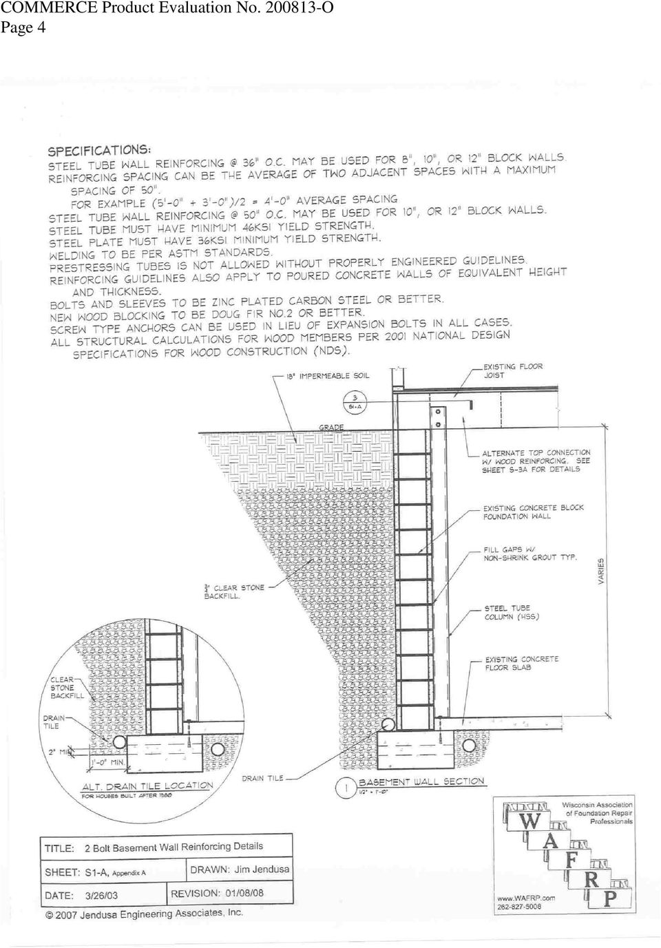
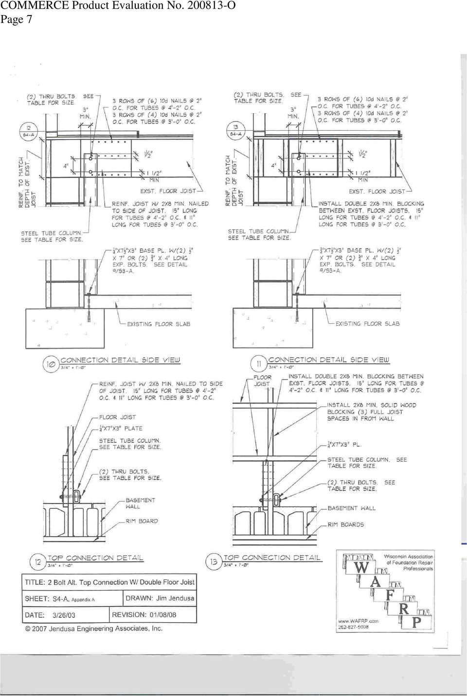
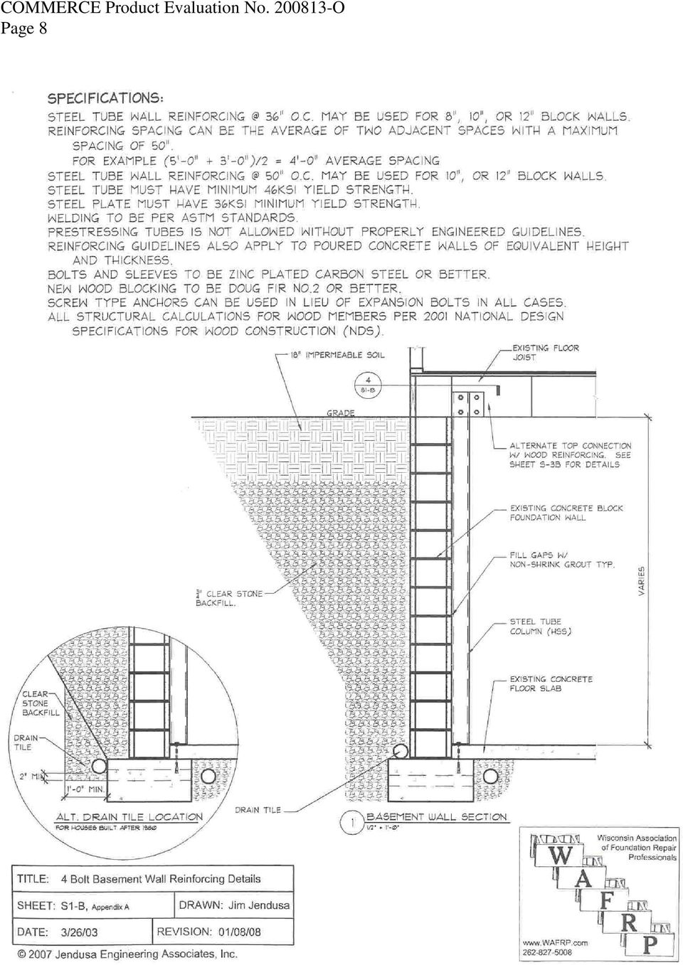
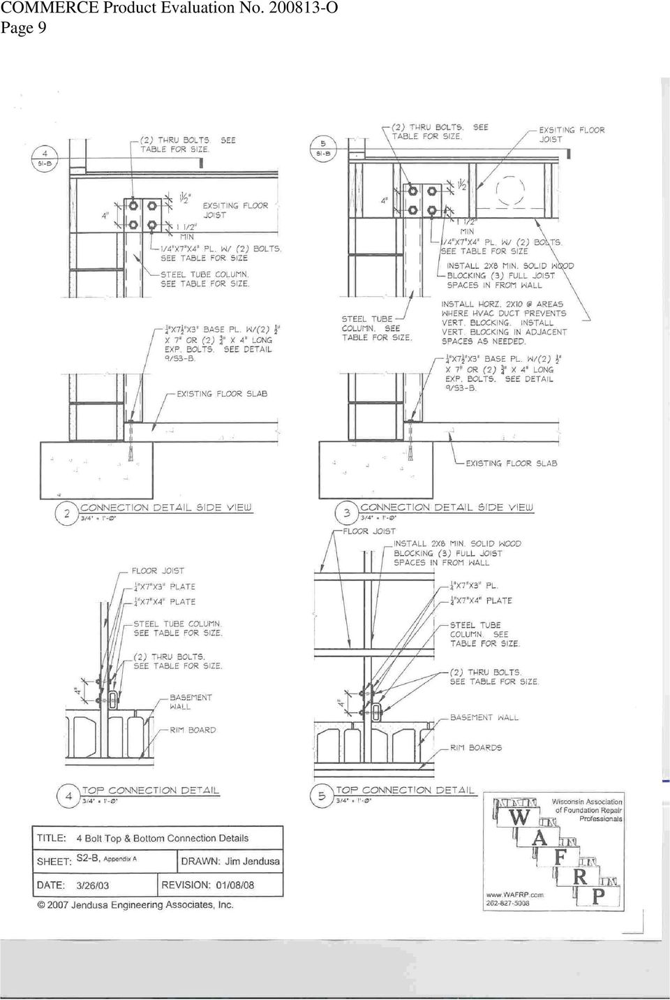
2 Page 2 Anchorage to Concrete Allowable Stress Design: The engineered foundation products were evaluated in accordance with the anchorage to concrete allowable stress design requirements of s. IBC Design Methods: The engineered foundation products were evaluated in accordance with the design method requirements of s. IBC Bolting: The engineered foundation products were evaluated in accordance with the bolting requirements of s. IBC Structural Steel: The engineered foundation products were evaluated in accordance with the structural steel requirements of s. IBC Wood: The engineered foundation products were evaluated in accordance with the general wood requirements of s. IBC General Construction Requirements: The engineered foundation products were evaluated in accordance with the general construction requirements of s. IBC Allowable Stress Design: The engineered foundation products were evaluated in accordance with the allowable stress requirements of s. IBC Conventional Light-Frame Construction: The engineered foundation products were evaluated in accordance with the conventional light-frame construction requirements of s. IBC DESCRIPTION AND USE The EFP Parts are installed at the top and bottom of each steel wall reinforcing column. The wall reinforcing is located at the on center spacing per engineering specifications located in Table 1. The EFP Parts are designed to be used with 2 inch wide steel tubes at various depths per engineering standards. Seismic forces need not be considered for the EFP Parts. This product does not affect the lateral force resisting system of the structure. ENGINEERED FOUNDATION PRODUCTS (EFP) Part 1: Saddle Top Connection: This part is a steel saddle that fits around a steel reinforcing tube. The saddle connection has (2) plates that fit on either side of a floor joist. The part is then bolted into place with (2) 5/8'' diameter bolts through the steel plates and floor joist and (1) 3/8'' diameter lag screw into the bottom of the floor joist. Part 2: Z Top Connection: This part consists of (2) steel plates. One plate is bent into a Z shape that fits against a steel reinforcing tube and floor joist. The other piece is a flat plate that sits on the back side of the floor joist. There are triangular teeth that push into the floor joist and holes for (2) 1/2'' diameter bolts that bolt through the plates and the floor joist. Part 3: Bottom Bracket: This part is a steel base plate with a vertical tab that fits into a steel reinforcing tube. There are (2) holes for anchor bolts to go through the base plate and into either a concrete floor slab or footing. Part 4: Offset Top Connection: This part is an offset extension accessory that is used with the saddle top connection or Z top connection when there is an obstruction preventing the placement of the top connection directly against the steel reinforcing tube. The extension is a steel tube that fits into the bottom of the saddle and has a U-shaped bent steel plate on the other end to fit around the basement wall reinforcing tube. The extension tube is held in place with 3/8'' diameter lag screws installed through the tube and into the bottom of the floor joist. The top connection is then secured with either a saddle or Z connector as described above. Part 5: Alternate Offset Top Connection: This part is an offset extension accessory that is used with the saddle top connection or Z top connection when there is an obstruction at the top of the wall. The extension is an L shaped steel tube. The vertical leg of the tube fits into the saddle top connection or a Z top connection. The horizontal leg of the tube sits on the top of the wall reinforcing tube. There are (2) 1/4'' thick steel plates on either side of the tubes fastening the wall reinforcing tube and the L tube with (4) 1/4'' TEK screws into both sides of each tube. The top connection is then secured with either a saddle or Z connector as described above. Part 6: Alternate Bottom Bracket: This part is a cast aluminum base plate with a vertical tab that fits into the steel tube. There are (2) holes for anchor bolts to go through the base plate and into either a concrete floor slab or footing. TESTS AND RESULTS Wisconsin Testing Laboratories, LLC conducted load tests on engineered foundation products Wall Restraint Top Connector Alternate #1. Test Results: The test specimen gradually rotated in the plane of loading, and the rotation became noticeable after the 6,500-lb. load level. The test was terminated at about 7,500-lbs. or, twice the design load of the product. After the load test was released, examination of the test specimen revealed that it had remained intact and firmly attached to the joist. The only observable deformation was a change in the angle of attachment between the horizontal attachment plate and the vertical portion of the unit. Conclusions: The ultimate load capacity of the product is at least twice the design load of 3,750-lbs. Wisconsin Testing Laboratories, LLC conducted load tests on engineered foundation products Wall Restraint Top Connector Alternate #2.

3 Page 3 Test Results: No significant deformation of the test specimen was noted at the 2,500, 5,000 and 6,500 lb. load levels. At about 7,500 lbs. or, twice the design load of the product, the wood joist failed. After the load test was released, examination of the test specimen revealed that it had remained intact, although a noticeable bending had occurred in the steel plate at the ends of the triangular stiffeners. The steel plate on the side holding the tube section had slid down the joist about ¼-inch, while the steel plate on the other side of the joist had not moved. Conclusions: The ultimate load capacity of the product is at least twice the design load of 3,750-lbs. Table 1 BASEMENT WALL REINFORCEMENT DESIGN (Table based on a 90 PCF soil pressure) STEEL SIZE SPACING and BLOCK SIZE 4'' x 2'' x 1/4'' 36'' Max. Spacing 8'', 10'' or 12'' 5'' x 2'' x 3/16'' 50'' Max. Spacing 10'' or 12'' SINGLE JOIST SIDE MOUNT (2) 1'' Dia. Bolts See Details 2-5 on S2-A (4) 1/2'' Dia. Bolts See Details 2-5 on S2-B (4) 5/8'' Dia. Bolts See Details 2-5 on S2-B WALL HEIGHT* 10 Courses (up to 6' -10'') DOUBLE JOIST SINGLE JOIST Or 2x8 min. nailed With SADDLE to side of joist (2) 5/8'' Dia. Bolts See Details on S4-A (2) 3/4'' Dia. Bolts See Details on S4-B (4) 1/2'' Dia. Bolts See Details on S4-B (2) 1/2'' Dia. Bolts See Details on S6 (2) 5/8'' Dia. Bolts See Details on S6- TJI JOIST (2) 1'' Dia. Bolts See Details 6-7 on S3-A (4) 5/8'' Dia. Bolts See Details 6-7 on S3-B STEEL SIZE SPACING and BLOCK SIZE 5'' x 2'' x 3/16'' 36'' Max. Spacing 8'', 10'' or 12'' 6'' x 2'' x 3/16'' 50'' Max. Spacing 10'' or 12'' SINGLE JOIST SIDE MOUNT (2) 1'' Dia. Bolts See Details 2-5 on S2-A (4) 1/2'' Dia. Bolts See Details 2-5 on S2-B (4) 3/4'' Dia. Bolts See Details 2-5 on S2-B WALL HEIGHT 11 Courses (6' -10'' to 7' -6'') DOUBLE JOIST SINGLE JOIST Or 2x8 min. nailed With SADDLE to side of joist (2) 5/8'' Dia. Bolts See Details on S4-A (2) 1'' Dia. Bolts See Details on S4-A (4) 1/2'' Dia. Bolts See Details on S4-B (2) 5/8'' Dia. Bolts See Details on S6 (2) 3/4'' Dia. Bolts See Details on S6- TJI JOIST (2) 1'' Dia. Bolts See Details 6-7 on S3-A (4) 3/4'' Dia. Bolts See Details 6-7 on S3-B STEEL SIZE SPACING and BLOCK SIZE 5'' x 3'' x 1/4'' 36'' Max. Spacing 8'', 10'' or 12'' 6'' x 3'' x 1/4'' 50'' Max. Spacing 10'' or 12'' SINGLE JOIST SIDE MOUNT (4) 5/8'' Dia. Bolts See Details 2-5 on S2-A (4) 3/4'' Dia. Bolts See Details 2-5 on S2-B WALL HEIGHT 12 Courses (7' -6''to 8' -2'') DOUBLE JOIST SINGLE JOIST Or 2x8 min. nailed With SADDLE to side of joist (2) 3/4'' Dia. Bolts See Details on S4-B (4) 1/2'' Dia. Bolts See Details on S4-B (2) 1'' Dia. Bolts See Details on S4-B (4) 5/8'' Dia. Bolts See Details on S4-B *Wall Height is top of floor to bottom of joist **Bottom Anchors : Min. (2) 1/2'' dia. x 7'' long expansion bolts into footing or (2) 3/4'' dia. x 4'' long expansion bolts min. 3'' into slab (2) 5/8'' Dia. Bolts See Details on S6 (2) 1'' Dia. Bolts See Details on S6- TJI JOIST (4) 5/8'' Dia. Bolts See Details 6-7 on S3-B (4) 3/4'' Dia. Bolts See Details 6-7 on S3-B

4 Page 4
5 Page 5

6 Page 6

7 Page 7
8 Page 8
9 Page 9
10 Page 10

11 Page 11

12 Page 12

13 Page 13

14 Page 14

15 Page 15

16 Page 16

17 Page 17 LIMITATIONS OF APPROVAL The Comm limitation requirements below are in accordance with the current Wisconsin Uniform Dwelling Code (UDC), for 1- & 2-family dwellings: Soil Lateral Loads: The engineered foundation products shall be installed in accordance with the foundation requirements of s. Comm 21.18(1)(c). Masonry Foundation Walls: The engineered foundation products shall be installed in accordance with the structural requirements of s. Comm 21.18(3)(b). Floor Design: The engineered foundation products shall be installed in accordance with the floor design requirements of s. Comm and this evaluation. Concrete Floors: The engineered foundation products shall be installed in accordance with the concrete floor requirements of s. Comm and this evaluation. Precast Concrete Floors: The engineered foundation products shall be installed in accordance with the precast concrete floor requirements of s. Comm and this evaluation. The IBC requirements below in accordance with the current Wisconsin Amended ICC Code: Soil Lateral Loads: The engineered foundation products shall be installed in accordance with the soil lateral load requirements of s. IBC and this evaluation. Soils and Foundations: The engineered foundation products shall be installed in accordance with the soil and foundation requirements of s. IBC 1801 and this evaluation. Foundation and Soils Investigation: The engineered foundation products shall be installed in accordance with the foundation and soil investigation requirements of s. IBC 1802 and this evaluation. Footings and Foundations: The engineered foundation products shall be installed in accordance with the footing and foundation requirements of s. IBC 1805 and this evaluation. Anchorage to Concrete Allowable Stress Design: The engineered foundation products shall be installed in accordance with the anchorage to concrete allowable stress design requirements of s. IBC and this evaluation. Bolting: The engineered foundation products shall be installed in accordance with the bolting requirements of s. IBC and this evaluation. Structural Steel: The engineered foundation products shall be installed in accordance with the structural steel requirements of s. IBC and this evaluation. Wood: The engineered foundation products shall be installed in accordance with the general wood requirements of s. IBC and this evaluation. General Construction Requirements: The engineered foundation products shall be installed in accordance with the general construction requirements of s. IBC 2304 and this evaluation. Allowable Stress Design: The engineered foundation products shall be installed in accordance with the allowable stress requirements of s. IBC 2306 and this evaluation. Conventional Light-Frame Construction: The engineered foundation products shall be installed in accordance with the conventional light-frame construction requirements of s. IBC 2308 and this evaluation. This approval will be valid through December 31, 2013, unless manufacturing modifications are made to the product or a re-examination is deemed necessary by the department. The product approval is applicable to projects approved under the current edition of the applicable codes. This approval may be void for project approvals made under future applicable editions. The Wisconsin Building Product Evaluation number must be provided when plans that include this product are submitted for review. DISCLAIMER The department is in no way endorsing or advertising this product. This approval addresses only the specified applications for the product and does not waive any code requirement not specified in this document. Revision Date: Approval Date: O.doc August 12, 2008 By: Lee E. Finley, Jr. Product & Material Review Integrated Services Bureau

The Do s and Don ts of Foundation Beam Installation. Presented By WAFRP Members:
 The Do s and Don ts of Foundation Beam Installation Presented By WAFRP Members: John Voight,, B-Dry B Systems of Milwaukee Robert Zidar, CRC Concrete Raising Corporation Jim Jendusa, Jendusa Design & Engineering
Residential Deck Safety, Construction, and Repair
 Juneau Permit Center, 4 th Floor Marine View Center, (907)586-0770 This handout is designed to help you build your deck to comply with the 2006 International Residential Building code as modified by the
Chapter 3 Pre-Installation, Foundations and Piers
 Chapter 3 Pre-Installation, Foundations and Piers 3-1 Pre-Installation Establishes the minimum requirements for the siting, design, materials, access, and installation of manufactured dwellings, accessory
BEST MANAGEMENT STANDARDS FOR FOUNDATION REPAIR
 BEST MANAGEMENT STANDARDS FOR FOUNDATION REPAIR MARCH 00 REVISED JANUARY 8, 008 Prepared in cooperation with the Building Inspectors Association of Southeastern Wisconsin www.biasew.org. /6/00 rev. 0/08/008
TEST REPORT. Rendered to: INTEX MILLWORK SOLUTIONS, LLC. For: Rigid Cellular PVC Guardrail System Hampton RS40
 TEST REPORT Rendered to: INTEX MILLWORK SOLUTIONS, LLC For: Rigid Cellular PVC Guardrail System Hampton RS40 Report No: Report Date: 07/26/13 130 Derry Court York, PA 17406-8405 phone: 717-764-7700 fax:
ICC-ES Evaluation Report
 ICC-ES Evaluation Report ESR-2369 Reissued May 1, 2010 This report is subject to re-examination in one year. www.icc-es.org (800) 423-6587 (562) 699-0543 A Subsidiary of the International Code Council
6 RETROFITTING POST & PIER HOUSES
 Retrofitting Post & Pier Houses 71 6 RETROFITTING POST & PIER HOUSES by James E. Russell, P.E. 72 Retrofitting Post & Pier Houses Retrofitting Post & Pier Houses 73 RETROFITTING POST AND PIER HOUSES This
LEGACY REPORT ER-5110. www.icc-es.org. ICC Evaluation Service, Inc. Reissued November 1, 2003. Legacy report on the 1997 Uniform Building Code
 LEGACY REPORT Reissued November 1, 2003 ICC Evaluation Service, Inc. www.icc-es.org Business/Regional Office # 5360 Workman Mill Road, Whittier, California 90601 # (562) 699-0543 Regional Office # 900
TYPICAL PATIO COVERS 111
 City of Laguna Niguel Building Division 30111 Crown Valley Pkwy Laguna Niguel, CA 92677 (949) 362-4360 FAX 362-4369 www.cityoflagunaniguel.org TYPICAL PATIO COVERS 111 PLEASE NOTE: This information Bulletin
Guidelines for Earthquake Bracing of Residential Water Heaters
 Guidelines for Earthquake Bracing of Residential Water Heaters Department of General Services Division of the State Architect 1102 Q Street, Suite 5100 Sacramento, CA 95814 Phone: (916) 324-7099 Fax: (916)
STRUCTURAL CONCEPT FOR LIGHT GAUGE STEEL FRAME SYSTEM
 Chapter 9 STRUCTURAL CONCEPT FOR LIGHT GAUGE STEEL FRAME SYSTEM 9.1 BACKGROUND Steel is widely used in the construction of multi-storey buildings. However, steel construction is seldom used and is traditionally
The Stabilizer TM. Benefits. www.griptite.com. Supplemental support system for sagging beams and floor joists within a crawl space
 The Stabilizer TM Supplemental support system for sagging beams and floor joists within a crawl space Pre-drilled holes in steel plate allow for connection to beam or floor joists. Benefits Levels and
COMMONLY USED RESIDENTIAL BUILDING CODES
 COMMONLY USED RESIDENTIAL BUILDING CODES INTERNATIONAL RESIDENTIAL CODE (2009) form revised 5/10 FOUNDATION 1. DESIGN OF FORMWORK. Section 1906.1 IBC 2009, Section R404.1.2.3.6 IRC 2009, ACI 318 Section
Uncovered Decks & Porches
 Uncovered Decks & Porches Building Guides for Homeowners Why Do I need a Permit? D I D Y O U K N O W? As owner-builder you are the responsible party of record on such a permit. If your work is being performed
Residential Decks. Planning and Development Services Department
 Building Safety Division 8500 Santa Fe Drive Overland Park, KS 66212 (913) 895-6225 Fax (913) 895-5016 Email: [email protected] Planning and Development Services Department Residential Decks
Detailing of Reinforcment in Concrete Structures
 Chapter 8 Detailing of Reinforcment in Concrete Structures 8.1 Scope Provisions of Sec. 8.1 and 8.2 of Chapter 8 shall apply for detailing of reinforcement in reinforced concrete members, in general. For
Mark Cramer Inspection Services, Inc.
 Mark Cramer Inspection Services, Inc. 492 Twentieth Avenue, Indian Rocks Beach, FL 34635-2970 (727) 595-4211 Fax (727) 596-7583 Certified Member #12085 American Society of Home Inspectors Construction
Seismic Technical Guide
 Technical Document Seismic Technical Guide Hanger Wire Attachment Code Requirements 1 The International Building Code (IBC) defines the requirement for hanger wire and their supports and attachment methods.
Guidelines for Earthquake Bracing Residential Water Heaters
 Guidelines for Earthquake Bracing Residential Water Heaters Department of General Services Division of the State Architect In accordance with the Health and Safety Code Section 19215, the Division of the
Top 10+ Mistakes of DWV plumbing design
 Top 10+ Mistakes of DWV plumbing design Listed below are the some of the most frequently missed items, noticed by our inspectors, at plumbing rough-in when non-plumbers attempt plumbing design. Most of
Policy on Water Heater Installations Policy No. UPC 510-1-94 Effective: September 1, 1995 Revised: February 10, 1996
 CITY OF SAN JOSE BUILDING DIVISION POLICY Policy on Water Heater Installations Policy No. UPC 510-1-94 Effective: September 1, 1995 Revised: February 10, 1996 All new and replacement water heaters installed
STANDARD OPEN PATIO COVER
 STANDARD OPEN PATIO COVER BUILDING & SAFETY DIVISION 201 E. LA HABRA BLVD. LA HABRA, CA 90631 62-90-9710 Call Before You Dig 1-800-227-2600 PLEASE NOTE: This information Bulletin is made available to assist
Formwork for Concrete
 UNIVERSITY OF WASHINGTON DEPARTMENT OF CONSTRUCTION MANAGEMENT CM 420 TEMPORARY STRUCTURES Winter Quarter 2007 Professor Kamran M. Nemati Formwork for Concrete Horizontal Formwork Design and Formwork Design
CPA Steel Stud Framing Page 1 of 11
 CPA Steel Stud Framing Page 1 of 11 STEEL STUD FRAMING General Requirements City of Palo Alto (CPA) Building Inspection Division 285 Hamilton Ave. Inspection Request: 650 329-2496 Building Division IVR#
Featuring TJ Rim Board and TimberStrand LSL
 #TJ-8000 SPECIFIER S GUIDE TRUS JOIST RIM BOARD Featuring TJ Rim Board and TimberStrand LSL Multiple thicknesses, grades, and products to cover all your rim board needs 1¼" Thickness matches lateral load
INSTALLING SEISMIC RESTRAINTS FOR MECHANICAL EQUIPMENT
 VISCMA 412/August 2014 INSTALLING SEISMIC RESTRAINTS FOR MECHANICAL EQUIPMENT August 2014 Developed originally by the Vibration Isolation and Seismic Control Manufacturers Association under a cooperative
HURRICANE MITIGATION RETROFITS FOR EXISTING SITE-BUILT SINGLE FAMILY RESIDENTIAL STRUCTURES
 HURRICANE MITIGATION RETROFITS FOR EXISTING SITE-BUILT SINGLE FAMILY RESIDENTIAL STRUCTURES 101 Retrofits Required. Pursuant to Section 553.844 553.884, Florida Statutes, strengthening of existing site-built,
June 2007 CHAPTER 7 - CULVERTS 7.0 CHAPTER 7 - CULVERTS 7.1 GENERAL
 7.0 7.1 GENERAL For the purpose of this manual, culverts are defined as structures that are completely surrounded by soil and located below the surface of the roadway parallel to the general direction
Designed and Engineered to Perform
 History EARTH CONTACT PRODUCTS, L.L.C., is a family owned company, based in Olathe, Kansas. This company was built upon Don May s U.S. Patented fourth-generation Steel Piering System that has led to the
TEST REPORT. Rendered to: FAIRWAY BUILDING PRODUCTS, LP. For: LandMarke Railing System. PVC Guardrail System "Patent Number 7,487,941"
 TEST REPORT Rendered to: FAIRWAY BUILDING PRODUCTS, LP For: LandMarke Railing System PVC Guardrail System "Patent Number 7,487,941" Report No: Report Date: 05/25/10 130 Derry Court York, PA 17406-8405
Wood Projects Outdoors. Post Hole Specifications. Deck Span Tables. www.jon Eakes.com
 Wood Projects Outdoors Post Hole Specifications & Deck Span Tables www.jon Eakes.com Building Fences The depth of the fence posts into the ground must be at least one foot below the frost level for your
RESIDENTIAL FOUNDATION GUIDELINE Johnson County, KS
 RESIDENTIAL FOUNDATION GUIDELINE Johnson County, KS Johnson County Building Officials Association January 2008 Residential Foundation Guideline Foundation designs for one-and two-family dwellings may use
MEZZANINE SPECIFICATIONS PART 1 GENERAL 1.1 SCOPE 1.2 APPROVED MANUFACTURER 1.3 REGULATORY ORGANIZATIONS AND GROUPS 1.4 QUALITY ASSURANCE
 MEZZANINE SPECIFICATIONS PART 1 GENERAL 1.1 SCOPE This specification is intended to describe the general requirements applicable to a proper structural mezzanine design. In addition, it is to serve as
1997 Uniform Administrative Code Amendment for Earthen Material and Straw Bale Structures Tucson/Pima County, Arizona
 for Earthen Material and Straw Bale Structures SECTION 70 - GENERAL "APPENDIX CHAPTER 7 - EARTHEN MATERIAL STRUCTURES 70. Purpose. The purpose of this chapter is to establish minimum standards of safety
Introduction...COMB-2 Design Considerations and Examples...COMB-3
 SECTION DIRECTORY General Information Introduction...COMB-2 Design Considerations and Examples...COMB-3 Combination Assembly Recommendations and Limitations Composite Configurations...COMB-4 Typical Sealant
K. D. FRAME ASSEMBLY FOR CLOSED STEEL STUD WALLS...Ins 10. FRAME INSTALLATION DETAILS FOR CLOSED STEEL STUD WALLS...Ins 11
 K. D. FRAME ASSEMBLY FOR MASONRY WALLS...........................Ins 2 FRAME INSTALLATION DETAILS FOR MASONRY WALLS......................Ins 3 INSTALLING EXISTING MASONRY WALL ANCHORS IN FRAME..................Ins
POST AND FRAME STRUCTURES (Pole Barns)
") POST AND FRAME STRUCTURES (Pole Barns) Post and frame structures. The following requirements serve as minimum standards for post and frame structures within all of the following structural limitations:
POST AND FRAME STRUCTURES (Pole Barns) Post and frame structures. The following requirements serve as minimum standards for post and frame structures within all of the following structural limitations:
9.8.1.1. General (1) This Section applies to the design and construction of interior and exterior stairs, steps, ramps, railings and guards.
 This Section applies to the design and construction of interior and exterior stairs, steps, ramps, railings and guards.") Section 9.8. Stairs, Ramps, Handrails and Guards 9.8.1. Application 9.8.1.1. General (1) This Section applies to the design and construction of interior and exterior stairs, steps, ramps, railings and
Section 9.8. Stairs, Ramps, Handrails and Guards 9.8.1. Application 9.8.1.1. General (1) This Section applies to the design and construction of interior and exterior stairs, steps, ramps, railings and
TEST REPORT. Rendered to: LMT-Mercer Group, Inc. For: PRODUCT: 4" x 4" and 5" x 5" PVC Porch Posts with Aluminum Reinforcing
 TEST REPORT Rendered to: LMT-Mercer Group, Inc. For: PRODUCT: 4" x 4" and 5" x 5" PVC Porch Posts with Aluminum Reinforcing Report No.: Report Date: 01/28/14 Test Record Retention Date: 12/20/17 130 Derry
PUMP JACK SYSTEM AND ACCESSORIES
 Pump Jack Model # 2200 A low cost, easy to operate, safe, portable scaffolding built of rugged steel. It's perfect for shingling, siding, sheathing, insulating, painting, building, roofing, home repair
Foundations 65 5 FOUNDATIONS. by Richard Chylinski, FAIA and Timothy P. McCormick, P.E. Seismic Retrofit Training
 Foundations 65 5 FOUNDATIONS by Richard Chylinski, FAIA and Timothy P. McCormick, P.E. 66 Foundations Foundations 67 FOUNDATIONS Let's assume that the retrofit has been done correctly from the roofline
SECTION 26 05 49 VIBRATION AND SEISMIC CONTROLS FOR ELECTRICAL SYSTEMS
 SECTION 26 05 49 VIBRATION AND SEISMIC CONTROLS FOR ELECTRICAL SYSTEMS PART 1 - GENERAL 1.1 SUMMARY A. This Section includes seismic restraints and other earthquake-damage-reduction measures for electrical
symptoms of a faulty foundation
 symptoms of a faulty foundation How does drought impact your home's foundation? For many Texas families, their home becomes the single largest investment and also the family fortune. The home's foundation
Owner's Manual & Assembly Instructions
 Owner's Manual & Assembly Instructions PM01 BASE KIT Model No. FDN1014 717090311 CAUTION: SOME PARTS HAVE SHARP EDGES. CARE MUST BE TAKEN WHEN HANDLING THE VARIOUS PIECES TO AVOID A MISHAP. FOR SAFETY
This handout is a guide only and does not contain all of the requirements of the Minnesota State Building Code or city ordinances.
 Residential Decks Community Development Department Building Inspections Division 5200 85 th Avenue North / Brooklyn Park, MN 55443 Phone: (763) 488-6379 / Fax: (763) 493-8171 6/15 www.brooklynpark.org
What is Seismic Retrofitting?
 What is Seismic Retrofitting? SEISMIC RETROFITTING A Seismic Retrofit provides existing structures with more resistance to seismic activity due to earthquakes. In buildings, this process typically includes
Foundation Code compliance and Best Practices By Michael Coello
 Foundation Code compliance and Best Practices By Michael Coello Background Graduated cum laude in 1992 with a Bachelor of Science degree in finance from University of Wisconsin - Parkside Started poured
ICC-ES Evaluation Report Reissued September, 2010 This report is subject to re-examination in one year.
 ICC-ES Evaluation Report ESR-2270 Reissued September, 2010 This report is subject to re-examination in one year. www.icc-es.org (800) 423-6587 (562) 699-0543 A Subsidiary of the International Code Council
Draft Table of Contents. Building Code Requirements for Structural Concrete and Commentary ACI 318-14
 Draft Table of Contents Building Code Requirements for Structural Concrete and Commentary ACI 318-14 BUILDING CODE REQUIREMENTS FOR STRUCTURAL CONCRETE (ACI 318 14) Chapter 1 General 1.1 Scope of ACI 318
Ceiling Mounted Folding Attic Ladders Installation Instructions
 Ceiling Mounted Folding Attic Ladders Installation Instructions WARNING Before you start installing your new Louisville Ceiling Mounted Folding Attic Ladder, you must read and understand the following:
LAYING BLOCK AND BRICK
 LAYING BLOCK AND BRICK Products highlighted in this section: SAKRETE Type N Mortar Mix SAKRETE Type S Mortar Mix Brick And Block Laying Basics The first step in building a brick or block wall is to construct
WHI 90-Minute Rated Veneered Door Frame Installation Instructions
 No. 940-03-10 INSTALLATION INSTRUCTIONS 90 MINUTE RATED VENEERED DOOR FRAME DOOR REQUIREMENTS: Consult the door manufacturer to make sure that the doors are qualified for the hardware to be installed,
SINGLE-FAMILY EARTHQUAKE (SEISMIC) RETROFITS
 RETROFITS") CITY OF BEAVERTON Community Development Department Building Division 12725 SW Millikan Way / PO Box 4755, Beaverton, OR 97076 Phone: (503) 526-2493 Fax: (503) 526-2550 General Information (503) 526-2222
CITY OF BEAVERTON Community Development Department Building Division 12725 SW Millikan Way / PO Box 4755, Beaverton, OR 97076 Phone: (503) 526-2493 Fax: (503) 526-2550 General Information (503) 526-2222
EXTeRUS. EXTeRUS - With patented design, able to join technology. and quality of materials with a charming shape. Unique
 EXTeR US G L A S S - With patented design, able to join technology and quality of materials with a charming shape. Unique thanks to its outstanding loading capability with 150 kg maximum weight and height
Chapter 3 FOUNDATIONS AND FOUNDATION WALLS
 Chapter 3 FOUNDATIONS AND FOUNDATION WALLS This chapter discusses foundations and foundation walls constructed using the two most common foundation materials concrete and masonry. Although the IRC permits
Chapter 6 ROOF-CEILING SYSTEMS
 Chapter 6 ROOF-CEILING SYSTEMS Woodframe roof-ceiling systems are the focus of this chapter. Cold-formed steel framing for a roof-ceiling system also is permitted by the IRC but will not be discussed;
REPORT HOLDER: JENWEST ENTERPRISES LLC, DBA ADVANCED CONNECTOR SYSTEMS 321 SOUTH 1240 WEST #15 LINDON, UTAH 84042 EVALUATION SUBJECT:
 0 ICC ES Report ICC ES (800) 423 6587 (562) 699 0543 www.icc es.org 000 Most Widely Accepted and Trusted ESR 3635 Reissued 04/2016 This report is subject to renewal 04/2018. DIVISION: 03 00 00 CONCRETE
FRAME PROFILE MASONRY METAL DOOR FRAME FLUSH MASONRY KD MITER CORNER JOINT. #8 Screw (MS002485) Required on all fire rated KD frames. Bend Tabs.
 Required on all fire rated KD frames. Bend Tabs.") FRAME PROFILE MASONRY FLUSH MASONRY KD MITER CORNER JOINT Bend Tabs Head #8 Screw (MS002485) Required on all fire rated KD frames Corner Assembly 2" (50.8) Head Jamb Head Break Away Corner Clip Spot Welds
FRAME PROFILE MASONRY FLUSH MASONRY KD MITER CORNER JOINT Bend Tabs Head #8 Screw (MS002485) Required on all fire rated KD frames Corner Assembly 2" (50.8) Head Jamb Head Break Away Corner Clip Spot Welds
4. ANCHOR BOLTS AND STRAPS a. ½" anchor bolts shall be embedded 7" into concrete a maximum of 6' on center and 12" from corners and ends of plates.
 GENERAL CODE REQUIREMENTS (BASEMENTS) 1. FOOTINGS a. Footings shall be below frost line depth (42"). b. For an 8" foundation wall, footings shall be no less than 8" deep and 16" wide. c. Steel reinforcement
Connection Solutions
 Connection Solutions DESIGN BUILD SYSTEM Connection Solutions for Cold formed Steel Construction Complies with; AS/NZS 4600:2005 AISI S100:2007 AS/NZ 1397 ASTM A653 DESIGN & BUILD SYSTEM FRAMECAD Construction
Timber Decks. Technical Note. March 2007
 Timber Decks Technical Note. March 2007 This Technical Note contains general information for residential timber decks and floor frame structures for veranda s, patios etc which are exposed to the weather.
necessary for years of satisfactory service. SmartBlock insulating form concrete walls share the
 Chapter 7 PLUMBING AND ELECTRICAL 7.1 Introduction to Plumbing and Electrical Consideration of support services such as plumbing and electrical systems from the preliminary schematics phase through final
MEDIUM FLAT PANEL DISPLAY STATIC MOUNT MSR Series
 INSTALLATION INSTRUCTIONS MEDIUM FLAT PANEL DISPLAY STATIC MOUNT The static mount accommodates medium flat panel displays weighing up to 125 lbs (57 kgs). The teardrop holes in the mount allow for quick
MANUFACTURED HOME INSTALLATION FOR PERMANENT FOUNDATIONS (TRANSVERSE FLOORS) (SUPPLEMENT TO MANUFACTURED HOME INSTALLATION MANUAL)
 (SUPPLEMENT TO MANUFACTURED HOME INSTALLATION MANUAL)") MANUFACTURED HOME INSTALLATION FOR PERMANENT FOUNDATIONS (TRANSVERSE FLOORS) (SUPPLEMENT TO MANUFACTURED HOME INSTALLATION MANUAL) NOTE: THIS MANUAL IS INTENDED TO INSTRUCT AND TO ASSIST ALREADY QUALIFIED
MANUFACTURED HOME INSTALLATION FOR PERMANENT FOUNDATIONS (TRANSVERSE FLOORS) (SUPPLEMENT TO MANUFACTURED HOME INSTALLATION MANUAL) NOTE: THIS MANUAL IS INTENDED TO INSTRUCT AND TO ASSIST ALREADY QUALIFIED
PRE-ASSEMBLED INSTALLATION INSTRUCTIONS FOR PACB SERIES COAL FIRED OVENS
 PRE-ASSEMBLED INSTALLATION INSTRUCTIONS FOR PACB SERIES COAL FIRED OVENS OVENS MANUFACTURED BY: EARTHSTONE OVENS-6717 SAN FERNANDO RD GLENDALE CA 91201 TELEPHONE: 800-840-4915 818-553-1134 FAX: 818-553-1133
Report on. Wind Resistance of Signs supported by. Glass Fiber Reinforced Concrete (GFRC) Pillars
 Pillars") Report on Wind Resistance of Signs supported by Glass Fiber Reinforced Concrete (GFRC) Pillars Prepared for US Sign and Fabrication Corporation January, 2006 SUMMARY This study found the attachment of
Report on Wind Resistance of Signs supported by Glass Fiber Reinforced Concrete (GFRC) Pillars Prepared for US Sign and Fabrication Corporation January, 2006 SUMMARY This study found the attachment of
BEST MANAGEMENT STANDARDS FOR FOUNDATION REPAIR MARCH 2003 REVISED JUNE 13, 2012
 BEST MANAGEMENT STANDARDS FOR FOUNDATION REPAIR MARCH 2003 REVISED JUNE 13, 2012 Prepared in cooperation with the Building Inspectors Association of Southeastern Wisconsin www.biasew.net 1 BEST MANAGEMENT
Perforated Shearwall Design Method 1
 Perforated Shearwall Design Method 1 Philip Line, P.E., Bradford K. Douglas, P.E., American Forest & Paper Association, USA Abstract Wood frame shearwalls are traditionally designed using full-height shearwall
LEGACY REPORT. www.icc-es.org (800) 423-6587 (562) 699-0543 A Subsidiary of the International Code Council. *Corrected March 2014
 423-6587 (562) 699-0543 A Subsidiary of the International Code Council. *Corrected March 2014") ICC-ES Legacy Report PFC-3700* Issued October 2003 www.icc-es.org (00) 423-57 (52) 99-0543 A Subsidiary of the International Code Council Legacy report on the 1997 Uniform Building Code and the 2000 International
ICC-ES Legacy Report PFC-3700* Issued October 2003 www.icc-es.org (00) 423-57 (52) 99-0543 A Subsidiary of the International Code Council Legacy report on the 1997 Uniform Building Code and the 2000 International
The minimum reinforcement for the stem wall is the placement of:
 PolySteel creates an ideal insulated stem wall for concrete slabs that can make this part of your project easier and faster, in addition to making your finished project more energy-efficient. Figures 3.20
The better way to build TM. Installation Manual. FOUNDATION SIPs & FROST WALLS SIPs
 The better way to build TM Installation Manual FOUNDATION SIPs & FROST WALLS SIPs February 2016 PWF FOUNDATION & FROST WALL SIPs Installation Manual Table of Contents Topics General Requirements...................................
HUS-H Screw Anchor. Technical data. Seismic design data. HUS-H Carbon steel screw anchor. HUS-H diameter 8, 10, 14. Seismic design data
 Technical data HUS-H Carbon steel screw anchor HUS-H diameter 8, 10, 14 10 / 011 Version 011-10 1 HUS-H screw anchor seismic design data Anchor version Carbon steel screw Benefits - Quick and easy setting
DESIGN OF SLABS. 3) Based on support or boundary condition: Simply supported, Cantilever slab,
 Based on support or boundary condition: Simply supported, Cantilever slab,") DESIGN OF SLABS Dr. G. P. Chandradhara Professor of Civil Engineering S. J. College of Engineering Mysore 1. GENERAL A slab is a flat two dimensional planar structural element having thickness small compared
DESIGN OF SLABS Dr. G. P. Chandradhara Professor of Civil Engineering S. J. College of Engineering Mysore 1. GENERAL A slab is a flat two dimensional planar structural element having thickness small compared
Removable Aluminium posts
 Post Solent Sail Shades Ltd 120 Billington Gardens Hedge End Southampton SO30 2RT Tel/Fax: 01489 788243 www.solentsailshades.co.uk Email: [email protected] Removable Aluminium posts Single Pole
CONCRETE FLOOR SLAB & CASTING BED CONSTRUCTION
 CONCRETE FLOOR SLAB & CASTING BED CONSTRUCTION General 7 www.meadowburke.com 877-518-7665 MB1109 CONCRETE FLOOR SLAB AND CASTING BED CONSTRUCTION Quality Construction Begins at Ground Level Everything
Residential Foundations and Basements
 Residential Foundations and Basements Disclaimer All of the following information is based on the 2006 International Residential Code with Kentucky Amendments. As some information is paraphrased, article
Foundation Experts, LLC Specializes in Foundation Repair and Waterproofing
 1 Most basements show some signs of leaking and cracking. Through the years, problems with water, poor soils, grading, drainage and possible settling affect the integrity of a basement. Being able to recognize
ATI Evaluation Service A Division of Architectural Testing Certification Services
 ATI Evaluation Service A Division of Architectural Testing Certification Services Subject to Renewal: 09/01/2016 Issued: 09/04/2015 Visit www.ati-es.com for current status Page 1 of 17 UFP Ventures II,
CH. 2 LOADS ON BUILDINGS
 CH. 2 LOADS ON BUILDINGS GRAVITY LOADS Dead loads Vertical loads due to weight of building and any permanent equipment Dead loads of structural elements cannot be readily determined b/c weight depends
Aluminium systems profile selection
 Aluminium systems profile selection The purpose of this document is to summarise the way that aluminium profile selection should be made, based on the strength requirements for each application. Curtain
WORKPLACE SHELVING STORAGE RACKS SHOP FURNITURE & SPECIALTY STORAGE
 WORKPLACE SHELVING STORAGE RACKS SHOP FURNITURE & SPECIALTY STORAGE Look to Tri-Boro for: Outstanding Quality Affordable Pricing & Ontime Delivery Online PDF Catalog Pages Tri-Boro Shelving and Partition
SECTION 7 Engineered Buildings Field Investigation
 SECTION 7 Engineered Buildings Field Investigation Types of Data to Be Collected and Recorded A field investigator looking at engineered buildings is expected to assess the type of damage to buildings.
Installation guide for the SafeLine type anchorage device. Tested in compliance with EN 795: 1996. No.: SE-...
 Installation guide for the SafeLine type anchorage device Tested in compliance with EN 795: 1996 No.: SE-... Version: 09.10.2008 SE 67 Subject to technical alterations! Contents 1. General information
Cover. When to Specify Intermediate Precast Concrete Shear Walls. 10.10 Rev 4. White Paper WP004
 Cover Introduction In regard to precast concrete systems, the addition of two new categories of Seismic Force Resisting Systems (SFRS) in IBC 2006 has created some confusion about whether to specify intermediate
T-14 Tilt-Up Wall Braces
 T-14 Tilt-Up Wall s The Dayton Superior T-14 Tilt-Up Wall s are all steel, heavy duty wall braces designed to quickly and easily align and brace tilt-up wall panels. Rough adjustment of the T-14 braces
TEST REPORT. Report No.: A9814.01 109 44. Rendered to: BAMCO INC. Middlesex, New Jersey. PRODUCT TYPE: Wall Cladding System SERIES/MODEL: Dry Concept
 Architectural Testing TEST REPORT Report No.: A9814.01 109 44 Rendered to: BAMCO INC. Middlesex, New Jersey PRODUCT TYPE: Wall Cladding System SERIES/MODEL: Dry Concept AAMA 508 07, Voluntary Test Method
Chapter 3 - Structural Design
 Chapter 3 - Structural Design 3.0 General 3.0.1 Design Overview Greenhouse buildings are a complete structure including the structural support and enclosure elements. The primary structural system includes:
Superform Products Ltd.
 TYPICAL CORNER REINFORCING NOTE : SEE ENGINEERED REBAR SCHEDULES SUPPLIED BY THE MANUFACTURER STEEL REINFORCEMENT WALL CORNER 90 Copyright 2012 Sept. 2012 5.1.1 Rebar Spacing 6" 12" Max. Load LB./FT. 2000
Chapter. Earthquake Damage: Types, Process, Categories
 3 Chapter Earthquake Damage: Types, Process, Categories Earthquakes leave behind a trail of damage and destruction. People s lives are affected by the loss of loved ones, destruction of property, economic
4.3.5 - Breakaway Walls
 4.3.5 - Breakaway Walls Elevation of a structure on a properly designed foundation reduces the potential for water damage from flooding. When the space below the lowest elevated floor is maintained free
Trusted SECTION: 04 HILTI, INC. TULSA, Conformity! ICC-ES Evaluation. not specifically. Copyright 2015
 0 ICC ES Report ICC ES (800) 42 6587 (562) 699 054 www.icc es.orgg 000 Most Widely Accepted and Trusted ESR 2269 Reissued 02/205 This report is subject to renewal 02/207. DIVISION: 0 00 00 CONCRETE SECTION:
Services Enclosures and Protected Shafts - Maintaining Compartmentation
 Introduction When a fire resisting element is used to provide fire compartmentation, every opening that allows services to pass through the element must be adequately protected by sealing, or fire stopping
This mount uses concrete parking bumpers and a Davis tripod to create a mounting solution for nonpenetrable
 NON-PENETRATING FLAT ROOF MOUNT Application Note 18 For Any Davis Weather Station Installed on a Mounting Tripod Introduction This application note describes various mounting solutions for non-penetrable
INSTALLATION INSTRUCTIONS
 Turbo Tube Slide INSTALLATION INSTRUCTIONS C A U T I O N Do not climb on the outside of the slide This slide is designed for home use only, not for Public Playgrounds PlayCore, Inc. 2004 Copyrighted Material.
HUS-A 6 / HUS-H 6 / HUS-I 6 / HUS-P 6 Screw anchor in precast prestressed hollow core slabs
 HUS-A 6 / HUS-H 6 / HUS-I 6 / HUS-P 6 Screw anchor in precast Anchor version HUS-A 6 Screw with hex head HUS-H 6 Screw with hex head HUS-I 6 Screw with hex head Benefits - Quick and easy setting - Low
National Council of Examiners for Engineering and Surveying. Principles and Practice of Engineering Structural Examination
 Structural Effective Beginning with the April 2011 The structural engineering exam is a breadth and exam examination offered in two components on successive days. The 8-hour Vertical Forces (Gravity/Other)
DIY ALL STEEL SHED FRAMES
 DIY ALL STEEL SHED FRAMES FAST FIT FRAMES & CONNECTOR PRICES BELOW THE BEST BUILDINGS START WITH A STEEL BUILDING FRAME ALLOW 10-21 WORKING DAYS FROM DATE ORDERED FOR PRODUCTION & SHIPMENT READY PRICES
HORIZONTAL INSTALLATION
 THERMO/SOLAR Žiar s.r.o. MANUAL FOR INSTALLATION PV SUPPORTING FRAMES HORIZONTAL INSTALLATION Technical alternation reserved A1410 1 12/2014 CONTENT ORD.NO. PAGE Mounting information 3 Mounting, flat roof
Wood Decks Zoning and construction requirements for open non-sheltered wood decks for residential dwellings.
 PLANNING, PROPERTY AND DEVELOPMENT DEPARTMENT Wood Decks Zoning and construction requirements for open non-sheltered wood decks for residential dwellings. September 2015 2 contents General Information