Electrical Essentials for HVAC&R Engineers. Wednesday, October 7
|
|
|
- Abigayle Osborne
- 9 years ago
- Views:
Transcription
1 Electrical Essentials for HVAC&R Engineers Wednesday, October 7

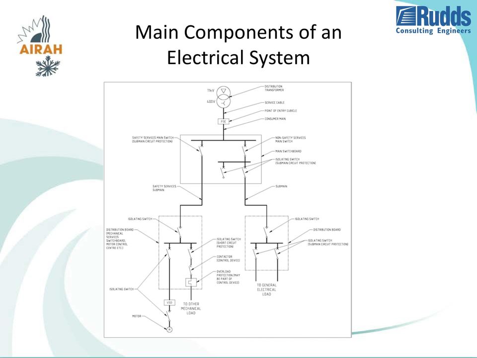
2 Main Components of an Electrical System
3 Accessibility of Switchboards AS/NZS REQUIRES SWITCHBOARDS TO HAVE ADEQUATE SPACE TO ALLOW EQUIPMENT TO BE SAFELY OPERATED AND ADJUSTED AND WITH SUFFICIENT EXIT FACILITIES TO ALLOW A PERSON TO LEAVE IN EMERGENCY CONDITIONS IN VERY SIMPLE TERMS THIS REQUIRES 600 mm CLEARANCE ALL AROUND WITH DOORS IN THE OPEN POSITIONS

4 FIGURE 2.16 FROM AS/NZS

5 FIGURE 2.17 FROM AS/NZS

6 FIGURE 2.15 FROM AS/NZS

7 FIGURE 2.16 FROM AS/NZS

8 Large Switchboards AS/NZS 3000 requires that any large switchboard be located in a room with two egress paths. What is a large switchboard? A current rating of over 800 Amps. A short circuit current of over 16kA. A length of over 3m. Multiple switchboards located side by side over 3m are considered to be a large switchboard. Exception: FAQ 030/2009: AS/NZS 3000:2007 CLAUSE (c)(ii) allows a large switchboard to have only a single egress path if a clearance of 3 metres is provided around the switchboard and its equipment, including switchboard doors, in all normal positions of operating, opening and withdrawal.

9 Diversity and Maximum Demand What is diversity? Diversity is an allowance that all connected equipment will not operate at full load at the same time. Maximum Demand is the sum of the connected loads with diversity applied. How to determine diversity? AS/NZS 3000 Table C2 provides diversity calculations.

10 Diversity and Maximum Demand

11 Maximum Demand How to determine the full load of a motor? 1. Use the motor AOM rated power. Maximum that can be drawn by the motor. Will result in oversized electrical infrastructure. 4.4kW from fan data. 2. Use the motor IEC power from nameplate. Will be conservative but closer to the operating point than AOM. Will still result in oversized electrical infrastructure but not as much. 4kW from data sheet. 3. Calculate operating point from data sheet. Is the maximum that the fan will draw in the design condition. Gives the best match of electrical infrastructure to mechanical demand. Calculated by taking the fan absolute power and dividing by motor efficiency. 3.23/0.896 = 3.6kW from data sheet. Redundant or duty/standby equipment Calculate maximum demand only on equipment that operates. If a system is N+1 then calculate maximum demand on N. If duty/standby then calculate maximum demand using only the duty unit. High duty installations Make the electrical designers aware if multiple items will operate at full load together e.g. Data centre, be aware of Table C in these environments.

12 Voltage Drop What is voltage drop? The reduction in voltage caused by current flow in the cables. Determined by ohms law, V = IR. Also dependent on power factor, typically lower power factor gives higher voltage drop. Why is voltage drop a problem? AS/NZS 3000 mandates maximum voltage drop of either 5% or 7%. 5% for shared and off-site substations. 7% for dedicated on-site substations. Can stop DOL or delta-star motors from starting. Too high a volt drop results in insufficient torque to start the motor. DOL motors in particular have high starting current and low power factor resulting in high volt drop. Correct voltage drop calculations require a knowledge of the entire electrical system from the substation to the load. Can be a problem for mechanical contractors if the electrical data is not provided.

13 Harmonics What are harmonics? Higher frequency components that add together to create a distorted waveform. Are always multiples of the fundamental frequency of 50Hz. Usually referred to by their harmonic number. 3 rd harmonic = 3 x 50Hz = 150Hz 4 th harmonic = 4 x 50Hz = 200Hz 5 th harmonic = 5 x 50Hz = 250Hz etc. Usually only odd numbered harmonics are present; 3, 5, 7, 9 etc. Why are harmonics a problem? High frequency components cause excessive power loss and heating in motors, capacitors, transformers etc. Triplen harmonics (multiples of 3 such as 3, 9, 15 etc.) add in neutral cables and can cause overloads.

14 Harmonics What are the sources of harmonics? VSDs are the number one source of harmonics in a typical building.

15 /// Harmonic Solutions Summary Passive: DC-Inductors AC-inductors Built-in as Standard Practical / Easy Active: /// Sizable High mitigation Retrofit-able Efficient (sleep mode) d D y 12 & 18-pulse Low cost Robust Active filter & Low Harmonic Drive D +20% -20% 0% Advanced Harmonic Filters Low cost Robust Efficient /// Active Front End Compact Easy to spec. High mitigation 100% Regenerative VSD Design Best Practice 26 May

16 Introduction Sources of EMI Harmonics RFI Harmonics cover frequencies from 50Hz to 2.5kHz (50 th harmonic) Standard: AS RFI is Conducted up to 30MHz, airborne over 30MHz Standard: AS (up to 30MHz) VSD Design Best Practice 26 May

17 Effects Worst case scenario Equipment Malfunction Potential bearing damage Without a screen the motor cable radiates RFI Common mode currents travel back to the drive via the earth connections, through the motor (potential bearing failure) This also causes problems for sensitive equipment on the mains supply also connected to the earth point i.e. instrumentation VSD Design Best Practice 26 May

18 Solutions Limiting conducted RFI Conducted RFI from the motor travels back to its source along the motor cable screen therefore motor cable screen MUST BE TERMINATED AT BOTH ENDS RFI filter provides a low impedance path for the RFI noise to travel back to it s source i.e. the d ive. Without F the R I filter Fthe R I noise tries to travel back to source through the mains Reduction of Capacitive and Inductive coupling into other cables (comms / signal) can be achieved by physical separation of cables VSD Design Best Practice 26 May

19 Solutions EMC glands Pigtails Pigtails need to be avoided as they: Act as antennae radiating noise Increase the screen impedance, and so increase conducted noise on mains supply On signal cables Pigtails receive EMI from other circuits EMC cable glands ensure a good highfrequency connection of the shield EMC cable glands should be used at the motor terminal box VSD Design Best Practice 26 May

20 EMC Standards IEC/EN Environments VSD Design Best Practice 26 May

21 EMC Standards Category Classification AS/NZS CISPR11 / EN55011 is a standard which defines limits according to the basic environment, it used to be the only standard which could be applied to electrical drives AS (AKA EN/IEC ) is a specific standard for electrical drive systems Facility operators must comply with AS/NZS CISPR11 / EN55011 Drive manufacturers must comply with EN VSD Design Best Practice 26 May
22 Earthing What is earthing? The connection of the general electrical installation to the ground. Why earth the electrical system? To protect against indirect contact by the automatic disconnection of supply. Indirect contact is contact with conductive parts that are not normally live but may become live in a fault situation such as a phase to earth fault. Automatic disconnection of supply is the tripping of a protective device such as a circuit breaker or fuse by the current produced by a phase to earth fault (earth fault loop). How is the electrical system earthed? By a continuous conductor connected to the exposed conductive part to an earth stake or earth mat. By the connection of the electrical system neutral conductor to earth at a single point in the electrical installation (MEN link). Equipotential bonding Electrical connections intended to bring exposed conductive parts or extraneous conductive parts to the same or approximately the same potential, but not intended to carry current in normal service.
23 The earth fault loop is the series of conductors that the current generated by an earth fault must pass through. Earth Fault Loop
24 Earth Fault Loop Impedance What is earth fault loop impedance? The impedance to current flow of the earth loop. Determines how much current flows for an earth fault. Determines the disconnect time in conjunction with the protective device setting.
25 Earth Fault Loop Disconnect Times AS/NZS 3000 mandates disconnect times for various parts of the electrical installation. An earth fault must be disconnected within 0.4s (400ms) for: Socket-outlets having rated currents not exceeding 63 A; or hand-held Class I equipment (equipment have a conductive outer case connected to earth); or (iii) portable equipment intended for manual movement during use. An earth fault must be disconnected within 5s for all other equipment.
26 How to Determine Disconnect Times AS/NZS 3000 Table 8.1 shows maximum line impedances for various types of breakers. Line impedances can be determined by measurement. Only provides 0.4s times for thermal magnetic breakers. For 0.4s disconnect times on electronic trip units set the short time setting at or below the earth fault current. Earth fault current = 230/Zs from ohms law (V=IR). For 5s disconnect times need to use breaker trip curves.
27 Overload and Short-circuit Protection AS/NZS 3000 requires that all cables be protected against both over load and short-circuit. Overload and short circuit protection may be combined in a device (circuit breaker or fuse) or by separate devices (thermal overload and circuit breaker or fuse). Overload protection is usually provided at the start of the cable but may be provided at the end under certain conditions (AS/NZS 3000 clause ) or even omitted (AS/NZS 3000 clause ). Short-circuit protection is provided at the start of the cable but may be provided within 3m of the start of the cable under certain conditions (AS/NZS 3000 clause ) or even omitted (AS/NZS 3000 clause ).
28 Protection Grading and Discrimination What is protection grading? Protection grading is ensuring that the protective device closest to the overload and short-circuit disconnects first to minimise the impact of the fault on the electrical system. Discrimination, selectivity and protection grading all describe the same thing. Total discrimination Total discrimination is when a smaller protective device is guaranteed to operate before a larger protective device under any circumstance. Only achievable by manufacturer s test between devices of the same manufacturer. Deemed Discrimination AS/NZS 3000 clause deems discrimination is achieved for certain settings.
29 Protection Settings Circuit breakers have various dials to adjust the protection settings. Long time settings. Long time settings protect against overload (low level currents) and may consist of a current setting and a time setting Short time settings Short time settings protect against high level currents and also may consist of a current setting and a time setting Instantaneous settings Instantaneous settings protect against very high level currents and also may consist of a current setting and a time setting
30 Protection Grading
31 Cascading Cascading is the use of protective devices with a fault current lower than the prospective fault current. Relies on an upstream device limiting the let through energy to below the rating of the device. Proven by manufacturer s testing. Only valid for the equipment that has been tested. Can t change manufacturer in system that rely on cascading. Systems that rely on cascading should be identified by labels in the switchboard This switchboard relies on cascading protection Do not use different manufacturer circuit breakers
32 Why does all this matter?
33 How did this happen?
34
35 How do you fix it?
36
37 Regulatory Regimes Generally building work including mechanical work is regulated through the building act and the national construction code
38 Electrical work is regulated via a different and independent system through the occupations licencing act and the electrical safety act
39 The construction occupations act covers ten occupations Asbestos Assessor Builder Building Assessor Building Surveyor Drainer Electrician Gasfitter Plumber Plumbing plan certifier Works Assessor
40 ELECTRICAL SAFETY ACT Calls up AS/NZS 3000 as the primary technical compliance standard. Requires electrical work to be carried out by someone who is licensed Punitive in application and defines offences if conditions are not met. The key features are Electrical work must be inspected tested and passed by an inspector before connection to the electricity network Electrical work must be carried out by licensed person Electrical work must be registered and notified to the registrar. (Access Canberra) Electrical work must be registered and as a result can be inspected Penalties apply for unsafe work Unsafe work can be disconnected. The act also defines roles and powers of inspectors, rectification of unsafe installations and covers electrical equipment approvals
41 AS/NZS Importantly the electrical safety act calls up AS/NZS as the primary standard for electrical work Unlike the National Construction Code that is a performance based code, AS/NZS is a prescriptive set of rules designed for application by electricians and electrical contractors.
42 WHY IS THIS IMPORTANT Electrical engineers and designers have no role whatsoever in the electrical approval process Regardless of an engineering design the electrical contractor is legally responsible for the electrical safety and compliance of electrical installations Electrical inspection in the act is very diligent The prescriptive nature of AS/NZS means that electrical designs need to be fully compatible with the standard. This raises potential for: Rejection of final installation by the inspector Delay in connection of supply Contract variations in order to achieve compliance.
43 SAFETY SERVICES EMERGENCY SYSTEMS ESSENTIAL LIFE SAFETY PLANT An understanding of safety services is important as it can influence mechanical plant layout and design Definitions: AS/NZS specifically uses the term SAFETY SERVICES This includes Fire and Smoke Control Equipment Fire hydrant pumps Fire detection and alarm systems Sprinkler pumps Air Handling systems that exhaust and control the spread of fire and smoke. Lifts and Items nominated as EMERGENCY EQUIPMENT in the NCC Building Code of Australia Just to make things interesting AS/NZS uses the term ESSENTIAL SERVICES
44 Control and Isolation Safety Services must be arranged so that control is separate from the control of other equipment Circuits for Safety services must be separate from other circuits Failure or fault on one safety service must not result in the loss of other safety services Faults in the general installation must not result in the loss of supply to safety services protection grading. There must be a metal barrier in the switchboard between safety services section and other sections of the switchboard
45 Control and Isolation Implications Avoid mechanical control panels that mix safety services and non-safety services Leave space for separate conduits or spacing between cable reticulation. Be careful in the design of electrical protection (see slides on discrimination)
46 Wiring Systems All wiring systems must have a WS classification in accordance with AS/NZS The selection of WS classification is determined by the relevant Standard The NCC BCA typically calls up WS 52W AS Appendix E describes wiring for Smoke controls The base requirement is for 120 minutes fire rating
47 APPENDIX E from AS/NZS
48 Wiring Systems AS/NZS AS/NZS 3013 is a test specification that allows cabling and other systems to be tested and certified for fire rating and mechanical strength. The first numeral is the fire rating. The second numeral describes mechanical resistance to impact A third item W can be added to include spraying with water after the fire test. The basic 2 hour fire rating is WS 5X Typically WS 52 is the commonly specified cabling system.
49 Wiring Systems AS/NZS Important things to know Access Canberra have a very literal and strict interpretation of fire rating of submains. Electrical contractors have to provide a dossier that supports the cable selection and the CABLE SUPPORT SYSTEM. This dossier must include certification of the cable and support system as well as certification that the system is supported from a 2 hour fire rated building element. There are very few certified cable support systems on the market In other words if it hasn t undergone a fire test to AS/NZS don t use it.
50 Wiring Systems AS/NZS Implications Natspec the standard standard clauses pass the responsibility on to the contractor. If you specify a cable type or document cable tray systems, you need to make sure that it is an approved system. The certified systems are expensive and bulky. Therefore you need to allow space for them in your planning. Existing cable systems although compliant when installed, may not meet current Standards AS/NZS 3013 has been amended and re-issued over time with revised testing and certification. Many existing systems that were certified in the past won t necessarily have certification to the current AS/NZS (MIMS cables are an example)
51 Generators and Redundancy ISSUES TO CONSIDER Types of transfer switch based on location Generators that back up safety services have additional conditions. Brief that require no break return to mains
52 Types of Transfer Switch 3 POLE 3 POLE Only used at a Main Switchboard Fig 2.2 from AS.NZS 3010
53 Types of Transfer Switch 3 POLE 4 POLE Used within an electrical installation away from the main Switchboard Fig 2.8 from AS.NZS 3010
54 4 POLE 4 POLE Only use this when you deliberately want to create a separated system. (Make sure the design is by an experienced electrical engineer) Fig 2.9 from AS.NZS 3010 Types of Transfer Switch
55 Transfer Switches Dangers and Risks if you get it wrong Circulating Neutral Currents Current can flow in the neutrals of circuits that have been isolated (safety risk) Currents can flow in earth cables. (Safety risk) Incorrect neutral connection Fault loop can be increased to the extent that protection doesn t trip on earth fault Incorrect use of 4 pole 4 pole Loss of neutral/earth reference if transfer switch fails in open position Loss of neutral/earth reference during transfer (Problem with down stream UPS)
56 Transfer Switches Types Location and Connection A good rule is to ensure that the specification references AS/NZS 3010
57 Considerations for Generators that support Safety Services THE GENERATOR ROOM MUST MEET 2 HOUR FIRE SEPARATION Generator room Supply Air and exhaust for generator cooling Fuel system THE CABLING SYSTEMS FROM THE GENERATOR TO THE SAFETY SERVICES MUST ACHIEVE WS 5X MINIMUM THE LOCATION OF THE GENERATOR CONNECTION IS LIMITED BY AS/NZS At the Main Switch Board At the safety services control panel
58 No Break Transfer BRIEFS THAT SPECIFY NO BREAK TRANSFER INTRODUCE ADDITIONAL REQUIREMENTS The ActewAGL service and installation rules will allow this under very strict conditions. If the transfer takes more than 400 milliseconds the system is considered to be an embedded generator. This requires a detailed formal submission to ActewAGL and imposes very strict control and protection requirements on the generator system. Typically costing $60,000 in protection and controls Short time parallel systems still require a formal submission but may not need the backup protection system. For these briefs make sure you engage qualified and experienced designer.
59 Questions
CHECKING AND TESTING ELECTRICAL INSTALLING WORK
 CHECKING AND TESTING ELECTRICAL INSTALLING WORK Department of Consumer and Employment Protection Energy Safety Preface It is a requirement of the Electricity (Licensing) Regulations 1991 that all electrical
DOMESTIC ELECTRICAL INSTALLATION CERTIFICATE (Requirements for Electrical Installations BS 7671 IEE Wiring Regulations)
") DOMESTIC ELECTRICAL INSTALLATION CERTIFICATE (Requirements for Electrical Installations BS 7671 IEE Wiring Regulations) DETAILS OF THE CLEINT Client and address ADDRESS OF THE INSTALLATION Installation
DOMESTIC ELECTRICAL INSTALLATION CERTIFICATE (Requirements for Electrical Installations BS 7671 IEE Wiring Regulations) DETAILS OF THE CLEINT Client and address ADDRESS OF THE INSTALLATION Installation
Comparative study for cables and busbars
 Comparative study for cables and busbars Preliminary considerations To compare the prices of two categories of product as different as traditional cables and busbars, it is necessary to make some preliminary
Unified requirements for systems with voltages above 1 kv up to 15 kv
 (1991) (Rev.1 May 2001) (Rev.2 July 2003) (Rev.3 Feb 2015) Unified requirements for systems with voltages above 1 kv up to 15 kv 1. General 1.1 Field of application The following requirements apply to
Specifying a Variable Frequency Drive s
 Specifying a Variable Frequency Drive s Put on by Bruce Reeves and Jeremy Gonzales Dykman Electrical Covering the Western US For all of your VFD and Soft Start and Motor Needs How To Specify a Variable
Release: 2. UEENEEJ194A Solve problems in low voltage refrigeration circuits
 Release: 2 UEENEEJ194A Solve problems in low voltage refrigeration circuits UEENEEJ194A Solve problems in low voltage refrigeration circuits Modification History Not Applicable Unit Descriptor Unit Descriptor
Video Camera Installation Guide
 Video Camera Installation Guide The intent of this guide is to provide the information needed to complete or modify a video camera installation to avoid lightning and induced power surge damage. This guide
415V DISTRIBUTION FOR GREEN DATA CENTERS
 White Paper: HMRP-WP001-A5 June 5, 2012 415V DISTRIBUTION FOR GREEN DATA CENTERS Prepared by: Anthony (Tony) Hoevenaars, P. Eng President and CEO Mirus International Inc. Copyright 2012 Mirus International
415V DISTRIBUTION FOR GREEN DATA CENTERS
 White Paper: HMRP-WP001-A1 October 1, 2010 415V DISTRIBUTION FOR GREEN DATA CENTERS Prepared by: Anthony (Tony) Hoevenaars, P. Eng President and CEO Mirus International Inc. Copyright 2005 Mirus International
VLT Series 3500 Adjustable Frequency Drive Instruction Manual
 Adjustable Frequency Drive Instruction Manual VLT Series 3500 Instruction Manual 175R5237 - Document Version 5.00 This manual applies to all VLT Series 3502-3800 Adjustable Frequency Drives with software
HARMONIC DISTORTION IN THE ELECTRIC SUPPLY SYSTEM
 Technical Note No.3 March 2000 HARMONIC DISTORTION IN THE ELECTRIC SUPPLY SYSTEM This Technical Note discusses harmonic distortion, its causes and adverse effects, what levels are unacceptable and how
GUIDE TO THE AM2 EXAM
 AM2 GUIDE TO THE AM2 EXAM What is AM2? AM2 or the Achievement Measurement 2 is a practical performance skill test administered by the National Electrotechnical Training (NET). You must take the AM2 test
Fundamentals of Power
 Fundamentals of Power Fundamentals of Power 2008 American Power Conversion Corporation. All rights reserved. All trademarks provided are the property of their respective owners. Learning Objectives At
White Paper: Electrical Ground Rules
 Acromag, Incorporated 30765 S Wixom Rd, Wixom, MI 48393 USA Tel: 248-295-0880 Fax: 248-624-9234 www.acromag.com White Paper: Electrical Ground Rules Best Practices for Grounding Your Electrical Equipment
Electrical Practices for Construction Work
 1. Purpose Electrical Practices for Construction Work The purpose of this Code is to provide practical guidance and set minimum safety requirements for electrical practices on all construction sites in
Transformerless UPS systems and the 9900 By: John Steele, EIT Engineering Manager
 Transformerless UPS systems and the 9900 By: John Steele, EIT Engineering Manager Introduction There is a growing trend in the UPS industry to create a highly efficient, more lightweight and smaller UPS
Technical Article. EMC filters for medical devices
 Technical Article EMC filters for medical devices September 2010 EMC filters for medical devices Schaffner, the market leader in EMC filters and power quality, has supplemented its proven IEC inlet filter
Power Quality for Information Technology System
 Power Quality for Information Technology System ITS OBVIOUS THE TOLERANCE IS DIFFRENT But What isn t Tobvious? HOW MANY OF YOU HAVE : A COMPUTER AT HOME? = Computers are not screens and Keyboards COMPUTERS
Low Voltage Products
 Low Voltage Products ABB Power Quality Filters: The most efficient solution for active filtering of harmonics, smooth reactive power compensation and load balancing. Enabling trouble-free and efficient
Drayton Digistat +2RF/+3RF
 /+3RF Programmable Room Thermostat Wireless Model: RF700/22090 Model: RF701/22092 Power Supply: Battery - Thermostat Mains - Digistat SCR Invensys Controls Europe Customer Service Tel: 0845 130 5522 Customer
Specification guide no. 9 Active harmonic conditioner from 20 to 480 A
 Active harmonic conditioner from 20 to 480 A Contents 1 - Installations concerned... 2 1.1 - New installations... 2 1.2 - Existing installations... 2 2 - General... 2 2.1 - Scope... 2 2.2 - Applicable
Electrical safety of grid-connected solar installations in Western Australia December 2011
 Electrical safety of grid-connected solar installations in Western Australia December 2011 Level 1, 303 Sevenoaks Street (cnr Grose Avenue) Cannington, Western Australia 6107 PO Box 135 Cannington WA 6987
SIZING THE PRIMARY POWER SYSTEM FOR RESISTANCE WELDERS
 SIZING THE PRIMARY POWER SYSTEM FOR RESISTANCE S By Jack Farrow, May, 2004 WELDING TECHNOLOGY CORPORATION ABSTRACT Information on how to select the correct size of substation transformer and 480V bus to
11. Assessment of service 12. S-phase supply 13. Water heaters NORTHERN TERRITORY OF AUSTRALIA ELECTRICITY BY-LAWS T ABLE OF PROVISIONS
 NORTHERN TERRITORY OF AUSTRALIA ELECTRICITY BY-LAWS T ABLE OF PROVISIONS By-law PART I - PRELIMINARY 1. Citation 2. Repeal 3. Interpretation 4. Qualifications of inspector PART II - INSPECTORS PART III
POWERING IN-FLIGHT ENTERTAINMENT EQUIPMENT FOR COMMERCIAL AIRCRAFT
 POWERING IN-FLIGHT ENTERTAINMENT EQUIPMENT FOR COMMERCIAL AIRCRAFT WHITE PAPER: TW0061 December 2008 R. DeLuca L. Rozenblat 1 About the Authors Ron DeLuca Ron DeLuca is Vice President - Engineering of
PROTECTION AGAINST ELECTRIC SHOCK by John Ware
 16 become live under fault conditions. The potential of the metal enclosure is higher than that of the main earthing terminal of the installation (and that of Earth) because of a potential difference created
12 SOLAR PHOTOVOLTAIC POWER SUPPLY SYSTEMS by John Ware. PV modules are current-limiting
 12 SOLAR PHOTOVOLTAIC POWER by John Ware IT IS PLANNED for BS 7671:2008 to include a new Section 712 providing additional requirements for safety applicable to solar photovoltaic (pv) power supply systems.
UNDERSTANDING AND CONTROLLING COMMON-MODE EMISSIONS IN HIGH-POWER ELECTRONICS
 Page 1 UNDERSTANDING AND CONTROLLING COMMON-MODE EMISSIONS IN HIGH-POWER ELECTRONICS By Henry Ott Consultants Livingston, NJ 07039 (973) 992-1793 www.hottconsultants.com [email protected] Page 2 THE BASIC
NZECP 14: 1995 ISSN 0114-0663 COVER PAGE
 NZECP 14: 1995 ISSN 0114-0663 COVER PAGE NZECP 14:1995 NEW ZEALAND ELECTRICAL CODE OF PRACTICE FOR CONTROL PROTECTION AND SWITCHBOARDS Issued by the Office of The Chief Electrical Engineer, Energy and
Harmonics and Noise in Photovoltaic (PV) Inverter and the Mitigation Strategies
 Inverter and the Mitigation Strategies") Soonwook Hong, Ph. D. Michael Zuercher Martinson Harmonics and Noise in Photovoltaic (PV) Inverter and the Mitigation Strategies 1. Introduction PV inverters use semiconductor devices to transform the
Soonwook Hong, Ph. D. Michael Zuercher Martinson Harmonics and Noise in Photovoltaic (PV) Inverter and the Mitigation Strategies 1. Introduction PV inverters use semiconductor devices to transform the
Trouble-shoot and repair faults in low voltage electrical apparatus and circuits
 UEENEEG108A Trouble-shoot and repair faults in low voltage electrical apparatus and circuits AS3000:2007 & AS3017:2007 Summary MANUFACTURING AND ENGINEERING DIVISI M & E UEENEEG108A TESTING Before any
Neutral Wire Facts and Mythology. White Paper #21
 Neutral Wire Facts and Mythology White Paper #21 Executive Summary This Technical Note discusses many common misunderstandings about the function of the neutral wire and its relation to power problems.
UNDERSTANDING POWER FACTOR AND INPUT CURRENT HARMONICS IN SWITCHED MODE POWER SUPPLIES
 UNDERSTANDING POWER FACTOR AND INPUT CURRENT HARMONICS IN SWITCHED MODE POWER SUPPLIES WHITE PAPER: TW0062 36 Newburgh Road Hackettstown, NJ 07840 Feb 2009 Alan Gobbi About the Author Alan Gobbi Alan Gobbi
Technical Description. Transistor D.C. Chopper Controller Type GS 24 S
 Technical Description Transistor D.C. Chopper Controller Type GS 24 S Table of contents 1. Getting started guide 2. General information 2.1. Characteristics 2.2. Accessories 3. Information about the Machine
employed to ensure the continuing reliability of critical systems.
 4 Regulations 1989, Regulation 4, places a duty on employers to provide safe systems for their workers: Regulation 4 of the Electricity at Work Regulations 1989 Systems, work activities and protective
Line Reactors and AC Drives
 Line Reactors and AC Drives Rockwell Automation Mequon Wisconsin Quite often, line and load reactors are installed on AC drives without a solid understanding of why or what the positive and negative consequences
Data Bulletin Variable Frequency Drives and Short-Circuit Current Ratings
 Data Bulletin Variable Frequency Drives and Short-Circuit Current Ratings 8800DB1203 03/2013 Retain for future use. Introduction Short-circuit current s (SCCRs) for variable frequency drives (VFDs) is
Type: DILM115(RAC240) Article No.: 239548 Sales text Contactor,55kW/400V,AC operated. Ordering information
 Article No.: 239548 Sales text Contactor,55kW/400V,AC operated. Ordering information") Type: DILM115(RAC240) Article No.: 239548 Sales text Contactor,55kW/400V,AC operated Ordering information Connection technique Description Description Rated operational current Screw terminals 3 pole AC
Type: DILM115(RAC240) Article No.: 239548 Sales text Contactor,55kW/400V,AC operated Ordering information Connection technique Description Description Rated operational current Screw terminals 3 pole AC
SUBJECT: How to wire a motor starter Number: AN-MC-004 Date Issued: 2/08/2005 Revision: Original
 SUBJECT: How to wire a motor starter Number: AN-MC-004 Date Issued: 2/08/2005 Revision: Original A motor starter is a combination of devices to allow an induction motor to start, run and stop according
Grounding Demystified
 Grounding Demystified 3-1 Importance Of Grounding Techniques 45 40 35 30 25 20 15 10 5 0 Grounding 42% Case 22% Cable 18% Percent Used Filter 12% PCB 6% Grounding 42% Case Shield 22% Cable Shielding 18%
Listed are common requirements that apply to existing solar installations when altered, added to or reconfigured.
 SOLAR ALTERATIONS REQUIREMENTS August 2015 These requirements address typical alterations to solar installations; they cannot address every scenario. In Victoria, an alteration to a solar installation
ARCO Electric Products Installation and Maintenance Manual Low Voltage Automatic Power Factor Correction Capacitor Systems 2013
 ARCO Electric Products Installation and Maintenance Manual Low Voltage Automatic Power Factor Correction Capacitor Systems 2013 READ CAREFULLY These instructions are intended to cover good practices in
Sentron Series Circuit Breakers
 Sentron Series Circuit Breakers Siemens Sentron Series circuit breakers are available in nine frame sizes: ED, FD, JD, LD, LMD, MD, ND, PD, and RD. Sentron Series circuit breakers have a wide range of
more than a breaker it s a breakthrough Compact NSX
 Compact NSX, more than a breaker it s a breakthrough Compact NSX 100-630 A Intelligent outlook Today, we are living in an increasingly booming and fast changing world where energy is key. More than ever,
FL ballasts Electronic dimming. PCA T5 BASIC lp Y II, 14 80 W BASIC T5
 T5 TC-L PCA T5 BASIC lp Y II, 1 80 W BASIC T5 Product description Processor-controlled ballast with y II inside Highest possible energy class CELMA EEI = A1 BAT 1 Noise-free precise control via DSI signal,
TIG INVERTER INSTRUCTION MANUAL
 TIG INVERTER INSTRUCTION MANUAL Contents Warning General Description Block Diagram Main Parameters Circuit Diagram Installation and Operation Caution Maintenance Spare Parts List Troubleshooting 3 4 4
PROPER SELECTION OF CONTROL CIRCUIT TRANSFORMERS WHITE PAPER BULLETIN 1497, 1497A, AND 1497B
 WHITE PAPER PROPER SELECTION OF CONTROL CIRCUIT TRANSFORMERS BULLETIN 1497, 1497A, AND 1497B CONTROL CIRCUIT TRANSFORMERS The proper selection of the control circuit transformers is important for suitable
EMC STANDARDS STANDARDS AND STANDARD MAKING BODIES. International. International Electrotechnical Commission (IEC) http://www.iec.
 http://www.iec.") EMC STANDARDS The EMC standards that a particular electronic product must meet depend on the product application (commercial or military) and the country in which the product is to be used. These EMC regulatory
EMC STANDARDS The EMC standards that a particular electronic product must meet depend on the product application (commercial or military) and the country in which the product is to be used. These EMC regulatory
conventional system operation
 conventional system operation detection line operation Conventional detection systems normally operate on a 24VDC line. In the standby condition, the detectors will draw a low current, typically less than
Use of Residual Current Devices in Departmental Infrastructure
 Technical Note TN145 Use of Residual Current Devices in Departmental Infrastructure July 2015 Copyright http://creativecommons.org/licenses/by/3.0/au/ State of Queensland (Department of Transport and Main
Current valve. for AC 24 V pulse/pause control of electrical loads up to 30 kw
 4 937 DESIO Current valve for AC 24 V pulse/pause control of electrical loads up to 30 kw SEA45.1 Use The current valve is used for the control of electric heating elements in heating, ventilation and
EMC Standards: Standards of good EMC engineering
 Electromagnetic Compatibility (EMC) IEEE Definition Origin, control, and measurement of electromagnetic effects on electronic and biologic systems. IEEE EMC Society Areas of Interest EMC Standards: Standards
Current Probes. User Manual
 Current Probes User Manual ETS-Lindgren L.P. reserves the right to make changes to any product described herein in order to improve function, design, or for any other reason. Nothing contained herein shall
Heading FACT SHEET. Overview. www.safeworkaustralia.gov.au
 ELECTRICAL RISKS AT THE WORKPLACE Heading FACT SHEET Overview This fact sheet provides general guidance for persons conducting a business or undertaking (PCBUs) and workers on managing electrical risks
HVAC Applications. VFD considerations for HVAC systems...
 HVAC Applications VFD considerations for HVAC systems... 1 COMMON TERMINOLOGY VFD (VARIABLE FREQUENCY DRIVES) AFC (ADJUSTABLE FREQ. CONTOLLER) ASD (ADJUSTABLE SPEED DRIVES) VSD (VARIABLE SPEED DRIVES)
Contractor Connect Scheme Electrical Contractor and Worker Handbook
 Contractor Connect Scheme Electrical Contractor and Worker Handbook January 2016 Document release information Document number 13553681 Document title Revision status Contractor Connect Scheme handbook
EVC40 EMERGENCY VOICE COMMUNICATION SYSTEM
 EVC40 EMERGENCY VOICE COMMUNICATION SYSTEM INSTALLATION MANUAL Protec Fire Detection PLC, Protec House, Churchill Way, Nelson, Lancashire, BB9 6RT. Telephone: +44 (0) 1282 717171 Fax: +44 (0) 1282 717273
ESP 120 M1, ESP 208 M1, ESP 240 M1, ESP 415 M1, ESP 277 M1, ESP 480 M1 and M1R variants. Installation instructions ESP M1/M1R mains protectors
 ESP 120 M1, ESP 208 M1, ESP 240 M1, ESP 415 M1, ESP 277 M1, ESP 480 M1 and M1R variants Installation instructions Contents Key points of installation Before installation Installation Installation check
ES281 COMPANY-SPECIFIC APPENDICES TO ENA ENGINEERING RECOMMENDATION G81 PART 1
 ES281 COMPANY-SPECIFIC APPENDICES TO ENA ENGINEERING RECOMMENDATION G81 PART 1 Design and Planning Specification for New Low Voltage Installations for Housing Developments 1. SCOPE This appendix to ENA
SIRIUX. SINGLE AND DOUBLE HIGH EFFICIENCY CIRCULATORS Heating Air-conditioning OPERATING LIMITS APPLICATIONS. 28 m 3 /h* Heads up to: Flows up to:
 OPERATING LIMITS Flows up to: m /h* Heads up to: m C Max operating pressure: bars Temperature range: - à + C Max ambient temperature: + C ND of orifices: à * m /h: parallel operation SIRIUX SINGLE AND
vacon ac drives for mining & minerals
 vacon ac drives for mining & minerals 1 strong experience in mining & minerals Vacon AC drives are robust to handle your most demanding requirements from simple ventilation to the most complex load sharing
LIMITING SHORT-CIRCUIT CURRENTS IN MEDIUM-VOLTAGE APPLICATIONS
 LIMITING SHORT-CIRCUIT CURRENTS IN MEDIUM-VOLTAGE APPLICATIONS Terence Hazel Senior Member IEEE Schneider Electric 38050 Grenoble France Abstract The power requirements for large industrial sites is increasing.
Residual Current Circuit Breaker
 Introduction Residual Current Circuit Breaker / ELCB The Fault current overloads and short circuits can be detected by circuit breakers like MCB s MCCB s & HRC Fuses etc. But, Circuit breakers don t detect
Electrical Shore Connections / Cold Ironing
 STANDARD FOR CERTIFICATION No. 2.25 Electrical Shore Connections / Cold Ironing JULY 2014 The electronic pdf version of this document found through http://www.dnv.com is the officially binding version
Customer Installation Safety Plan. March 2015
 Customer Installation Safety Plan March 2015 Document History Issue No. Date Approved By Summary of Changes 1 June 2014 Chief Engineer Updated and revised in line with requirement for biennial review under
Part 1 System Modeling & Studies for Existing Systems
 Part 1 System Modeling & Studies for Existing Systems Operation Technology, Inc. Copyright 2009 Result of rapid release of energy due to an arcing fault between two conductors. Bus voltages > 208V Temperatures
Protect your home and family with Advanced Technology from Cutler-Hammer
 Protect your home and family with Advanced Technology from Cutler-Hammer Residential Home Fire Statistics Annually - over 415,000 Residential Fires Annually - over 40,000 electrical fires over 350 deaths
SUGGESTED SPECIFICATION for Series 185 Service Entrance Rated Automatic Transfer Switches
 SUGGESTED SPECIFICATION for Series 185 Service Entrance Rated Automatic Transfer Switches PART 1 GENERAL 1.01 Scope Optional Standby Power Generator Systems A. Furnish and install automatic transfer switches
ELECTRICAL INSTALLATION CONDITION REPORT (Requirements for Electrical Installations BS 7671 IEE Wiring Regulations)
") Original Certificate DETAILS OF THE CLIENT Certificate reference: ELECTRICAL INSTALLATION CONDITION REPORT (Requirements for Electrical Installations BS 7671 IEE Wiring Regulations) Name: Address: PURPOSE
Original Certificate DETAILS OF THE CLIENT Certificate reference: ELECTRICAL INSTALLATION CONDITION REPORT (Requirements for Electrical Installations BS 7671 IEE Wiring Regulations) Name: Address: PURPOSE
Chapter 5. Components, Symbols, and Circuitry of Air-Conditioning Wiring Diagrams
 Chapter 5 Components, Symbols, and Circuitry of Air-Conditioning Wiring Diagrams Objectives Upon completion of this course, you will be able to: Explain what electrical loads are and their general purpose
Trial Exams C. Standards and Regulations. Examination No: GH-08-C- 1 hour and 5 minutes plus 10 minutes reading time
 Trial Exams C Standards and Regulations Examination No: GH-08-C- This test is intended to gauge your knowledge of essential information contained within AS/CA S009:2013. To qualify for an allpication to
Trade of Electrician. Three-phase Distribution Boards And Socket Circuits
 Trade of Electrician Standards Based Apprenticeship Three-phase Distribution Boards And Socket Circuits Phase 2 Module No. 2.3 Unit No. 2.3.2 COURSE NOTES Created by Charlie Walsh - Athlone TC Revision
PLEASE NOTE. For more information concerning the history of these regulations, please see the Table of Regulations.
 PLEASE NOTE This document, prepared by the Legislative Counsel Office, is an office consolidation of this regulation, current to August 1, 2013. It is intended for information and reference purposes only.
Power Quality Standards for Electric Service
 Power Quality Standards for Electric Service Effective June 1, 2008 A transition period will exist from June 1 through December 31, 2008 in which installations may be approved and connected as long as
CEMEP UPS. The high environmental performance solution for power supply to high-availability data centers
 CEMEP UPS The high environmental performance solution for power supply to high-availability data centers Exchanges of information and communication needs are growing at an exponential rate. That growth
Fire. The Fire Installers Mate. A guide to fire alarm systems design
 Fire The Fire Installers Mate A guide to fire alarm systems design BS 5839 Part 1:2002 A guide to BS 5839 Part 1:2002 Disclaimer This booklet is not intended to be a comprehensive guide to all aspects
6 ELECTRICAL PARAMETERS
 6 ELECTRICAL PARAMETERS For power, low voltage and medium voltage cables, cross section nominal areas are calculated in taking into account several parameters as: permissible current carrying capacities
Electrical Safety Tips. Help us keep you safe
 Electrical Safety Tips Help us keep you safe To help you stay safe when using electricity, ActewAGL has compiled these electrical safety tips. For natural gas safety tips please see ActewAGL s natural
Installation and safety instructions for AC/DC built-in devices
 The device type and date of manufacture (week/year) can be found on the device rating plate. In the event of any queries about the device, please quote all the details given on the rating plate. For further
NFPA 70E 2012 Rolls Out New Electrical Safety Requirements Affecting Data Centers
 NFPA 70E 2012 Rolls Out New Electrical Safety Requirements Affecting Data Centers A market position paper from the experts in Business-Critical Continuity TM Executive Summary Electrocutions are the fourth
Harmonics in your electrical system
 Harmonics in your electrical system What they are, how they can be harmful, and what to do about them Abstract Harmonic currents, generated by non-linear electronic loads, increase power system heat losses
ARC FLASH HAZARD OVERVIEW. Presented August 13, 2015 WWOA Lake Michigan District by Mead & Hunt, Inc.
 ARC FLASH HAZARD OVERVIEW Presented August 13, 2015 WWOA Lake Michigan District by Mead & Hunt, Inc. ARC FLASH EXPERIENCE Christopher J. DeWaal, MS, MEM, PE, LEED AP, HACCP How did I get involved? A client
S/PDIF D/A Converter. User Manual. Rev.B, December 2011 Audial d.o.o Belgrade, Serbia www.audialonline.com, [email protected]
 S/PDIF D/A Converter User Manual Rev.B, December 2011 Audial d.o.o Belgrade, Serbia www.audialonline.com, [email protected] IMPORTANT PRECAUTIONS 1. Do not expose this device to rain or moisture,
Circuit Electrical Testing
 Safe Isolation Procedure Circuit Electrical Testing Site Safety Management It is essential from the outset that effective management and control of the system, apparatus and equipment used on site is achieved
3-PHASE LOW VOLTAGE NETWORK LOAD BALANCER : A COST EFFECTIVE SOLUTION TO LINE VOLTAGE VARIATIONS
 3-PHASE LOW VOLTAGE NETWORK LOAD BALANCER : A COST EFFECTIVE SOLUTION TO LINE VOLTAGE VARIATIONS Pierre FRISTOT Olivier CONSTANT Catherine MONCET Omegawatt - France Omegawatt - France SDET - France [email protected]
Balanced vs. Unbalanced Audio Interconnections
 Revised 7/2/08 Balanced vs. Unbalanced Audio Interconnections In discussing the characteristics and performance of various interconnect systems; two points should be kept in mind. Balance is defined in
Cable Solutions for Servo and Variable Frequency Drives (VFD)
") Cable Solutions for Servo and Variable Frequency Drives (VFD) Electric drive systems with continuous torque and speed control are widespread today. They allow an optimal adjustment of the drive with respect
Cable Solutions for Servo and Variable Frequency Drives (VFD) Electric drive systems with continuous torque and speed control are widespread today. They allow an optimal adjustment of the drive with respect
SELECTION OF FINAL CIRCUIT PROTECTION
 SELECTION OF FINAL CIRCUIT PROTECTION By Phil Williams, Product Marketing Manager, Power Distribution Components, Eaton Executive summary The selection of devices for final circuit protection in electrical
Generator Stator Protection, under/over voltage, under /over frequency and unbalanced loading. Ramandeep Kaur Aujla S.NO 250447392
 1 Generator Stator Protection, under/over voltage, under /over frequency and unbalanced loading By Ramandeep Kaur Aujla S.NO 250447392 ES 586b: Theory and applications of protective relays Department of
The following table shows approximate percentage wise the
 SHORT-CIRCUIT CALCULATION INTRODUCTION Designing an electrical system is easy and simple, if only the normal operation of the network is taken into consideration. However, abnormal conditions which are
CONTROLS DATA MANAGEMENT PROCESS AUTOMATION EUROCUBE. General purpose single phase thyristors and solid state relays Product data.
 425 CONTROLS DATA MANAGEMENT PROCESS AUTOMATION EUROCUBE General purpose single phase thyristors and solid state relays Product data abc 425 EUROCUBE A complete range of low cost solid state relays and
Thyristor-controlled power supplies and battery chargers
 Thyristor-controlled power supplies and battery chargers Input voltage: 115 / 230 VAC, single phase, 50 / 60 Hz or 208 / 400 / 480 VAC, three phases, 50 / 60 Hz Output voltage: 12 / 24 / 48 / 60 / 72 /
CONTINUOUS MONITORING AND AVOIDANCE OF RESIDUAL CURRENTS IN DATA CENTRES WITH RCM White paper Revision 2
 IT Power Solutions CONTINUOUS MONITORING AND AVOIDANCE OF RESIDUAL CURRENTS IN DATA CENTRES WITH RCM White paper Revision 2 Thomas B. Jones 1 Introduction Operators and managers consider outages, operational
Type: DILM50(230V50HZ,240V60HZ) Article No.: 277830
 Article No.: 277830") Type: DILM50(230V50HZ,240V60HZ) Article No.: 277830 Ordering information Rated operational current AC 3 400 V I e A 50 Max. rating for three phase motors, 50 60 Hz AC 3 230 V Max. rating for three phase
Type: DILM50(230V50HZ,240V60HZ) Article No.: 277830 Ordering information Rated operational current AC 3 400 V I e A 50 Max. rating for three phase motors, 50 60 Hz AC 3 230 V Max. rating for three phase
A1000 Cheat Sheet (Open Loop Vector)
") A1000 Cheat Sheet (Open Loop Vector) The following procedure is a supplement to supplied with this equipment and will guide the user in properly wiring the A1000 and. It will also show the user how to
A1000 Cheat Sheet (Open Loop Vector) The following procedure is a supplement to supplied with this equipment and will guide the user in properly wiring the A1000 and. It will also show the user how to
EMI in Electric Vehicles
 EMI in Electric Vehicles S. Guttowski, S. Weber, E. Hoene, W. John, H. Reichl Fraunhofer Institute for Reliability and Microintegration Gustav-Meyer-Allee 25, 13355 Berlin, Germany Phone: ++49(0)3046403144,
Power Supplies 3. SDN-P DIN Rail Series
 SDN-P DIN Rail Series The SDN DIN Rail power supplies provide industry leading performance. Sag Immunity, transient suppression and noise tolerant, the SDN series ensures compatibility in demanding applications.
CONTRACTOR INDUCTION HANDBOOK
 CONTRACTOR INDUCTION HANDBOOK POLICY The health and safety of all school employees and contractor employees is a vital concern at the school. Contract personnel will be treated in a manner consistent with
Considering the effects of UPS operation with leading power factor loads
 Considering the effects of UPS operation with leading power factor loads Over the past five years, a new generation of data processing and communications equipment has become prevalent in modern data centers
Electrical Grounding. Appendix C
 Appendix C Electrical Grounding Low-Voltage Equipment Grounding The most frequently cited Office of Safety and Health Administration (OSHA) electrical violation is improper occupational grounding of equipment