Electronic Multi-Measuring Instrument
|
|
|
- Lizbeth Wilkins
- 9 years ago
- Views:
Transcription
1 MITSUBISHI Electronic Multi-Measuring Instrument Programming Manual (CC-Link) For ver.1 remote device station Model ME96NSR-MB or ME96NSR with Optional Plug-in Module : ME-0040C-NS96 ME96SSH-MB or ME96SSR-MB with Optional Plug-in Module : ME-0040C-SS96

2 CONTENTS 1. General Description Specification Configuration Conditions of CC-Link System Remote net ver.1 mode Remote net ver.2 mode Programming Programming Procedure Parameter Settings Procedure from Parameter Settings to Data Link Startup CPU Parameter Area and Master Module Parameter Memory Procedure for Parameter Settings to Data Link Startup with GX Developer Example of Parameter Settings with GX Developer Master Station Network Parameter Settings Communication Between the Master Station and ME Communication Guideline Initial Communication Error Communication Normal Communication Remote I/O and Remote Register Remote Input RX, Remote Output RY Remote input RX Remote Output RY Remote Register (RWr, RWw) Supported Commands Details of Commands Data format Multiplying Factor About Error Occurrence Abbreviations and Special Terms Program Example Program Content System Configuration Device Allocation Parameter Settings Network Parameter Settings and Auto Refresh Parameter Settings Operational Settings Station Information Settings Program Example Test Mode ME96SSH-MB/ME96SSR-MB ME96NSR (2/n)

3 1. General Description This manual describes the programming methods that should be created by the user for monitoring measurement value of the Electronic Multi-Measuring Instrument (called ME96 from here on) with the Control & Communication Link (abbreviated as CC-Link from here on). In programming, read the following related manuals in addition to this mannual. Table 1.1 Related Manuals Manual Name CC-Link System Master/Local Module User's Manual type QJ61BT11 CC-Link System Master/Local Module User's Manual type QJ61BT11N MELSEC-L CC-Link System Master/Local Module User's Manual FX2N-16CCL-M USER'S MANUAL FX3U-16CCL-M USER'S MANUAL User s Manual for ME96 Manual No. SH (13JL91) SH E (13JR64) SH ENG (13JZ41) JY992D93101 (09R710) JY997D43601 (09R724) Supplied with product or download. NOTICE When using ME96, Optional Plug-in Module ME-0040C-NS96 or ME-0040C-SS96 is necessary. CC-Link communication is not available without the optional plug-in module. In this manual, ME96NSR, ME96SSH-MB or ME96SSR-MB means the main device of ME96 with the optional plug-in module. POINT ME96SSH-MB/ME96SSR-MB must be handled after setting of the remote device station version. Set the remote device station version with the Setting Menu 2 of the ME96SSH-MB/ME96SSR-MB. Use the following as a guideline in setting the remote device station version and set the version at ME96. Mode select setting Guideline for selection Ver.1 remote device station Select this when utilizing the conventional program, because of (Ver.1 compatible slave station) compatibility with ME96NSR. Ver.2 remote device station Select this when configuring a new system or the being newly (Ver.2 compatible slave station) added to the existing system in combination with the applicable master module. This programming manual is for ver.1 remote device station. For use in the ver.2 remote device station (Ver.2 compatible slave station), refer to the following manual. Electronic Multi-Measuring Instrument Programing Manual (CC-Link)(For ver.2 remote device station)... LEN (3/n)

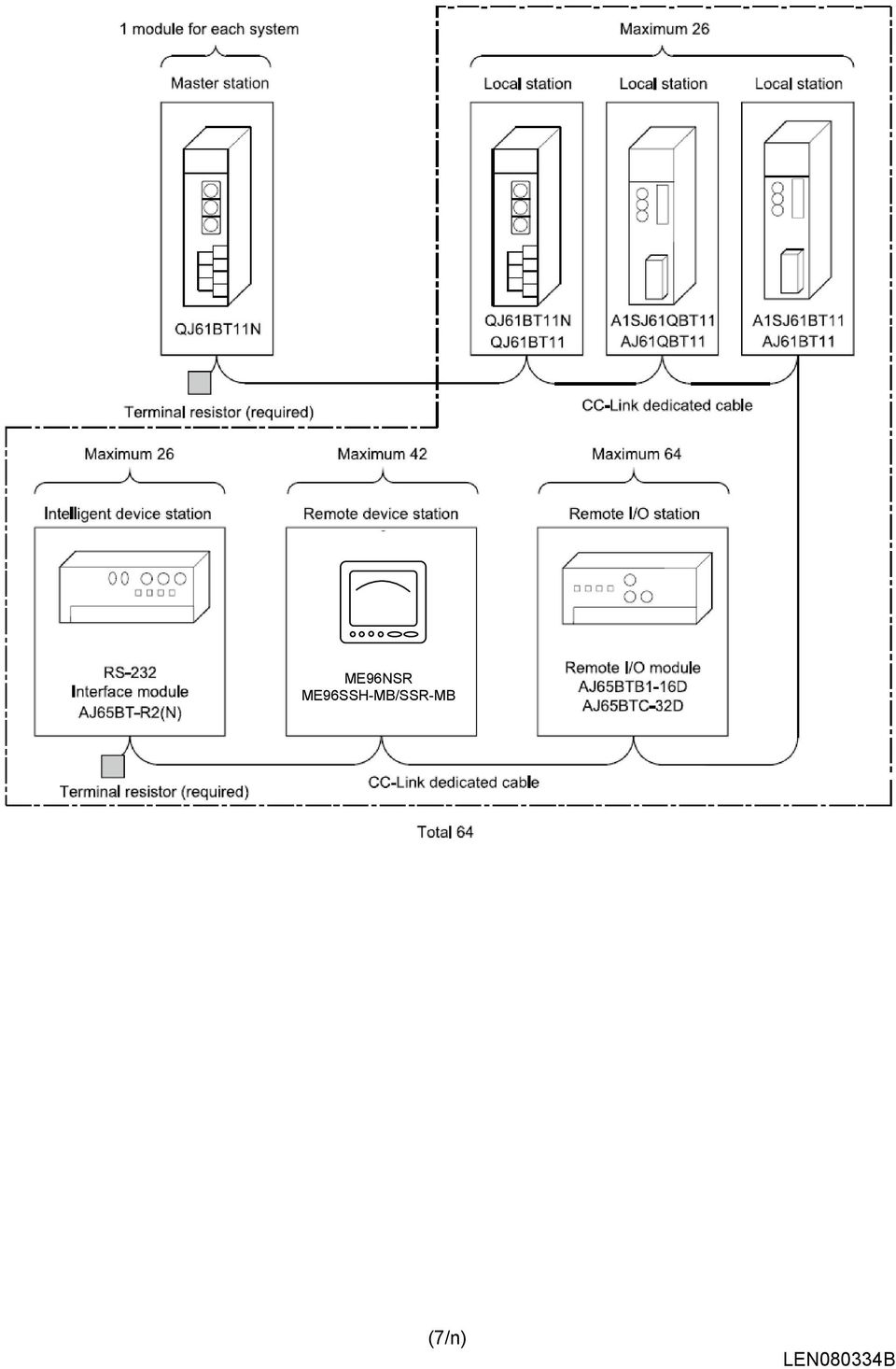
4 2. Specification ME96 specification is shown in Table 2.1. Table 2.1 CC-Link Specification Item CC-Link station type Number of occupied stations Maximum number of stations per master station Transmission speed Remote I/O (RX, RY) Remote register (RWw, RWr) Specification Remote device station (ver.1 remote device station) 1 station 42 stations ( In case of connecting only remote device station occupied by 1 station.) 156kbps/625kbps/2.5Mbps/5Mbps/10Mbps 32 points each 4 points each Master station ME96 ME96 ME96 Maximum number of connection is 42. (In case of ME96 connection.) ME96 ME96 ME96 System Configration (CC-Link) (4/n)
 Remote register (RWw, RWr) Specification Remote device station (ver.")
5 3. Configuration Conditions of CC-Link System 3.1 Remote net ver.1 mode A total of 64 remote I/O stations, remote device stations, local stations, standby master stations, or intelligent device stations can be connected to a single master station. However, the following conditions must all be satisfied. Condition 1 {(1 a)+(2 b)+(3 c)+(4 d)} 64 Condition 2 {(16 A) + (54 B) + (88 C)} 2304 a: Number of modules occupying 1 station (ME96 is applied) b: Number of modules occupying 2 stations c: Number of modules occupying 3 stations d: Number of modules occupying 4 stations A: Number of remote I/O stations 64 B: Number of remote device stations (ME96 is applied) 42 C: Number of local stations, standby master stations and intelligent device stations 26 ME96NSR ME96SSH-MB/SSR-MB (5/n)
+(2 b)+(3 c)+(4 d)} 64 Condition 2 {(16 A) + (54 B) + (88 C)} 2304 a: Number of modules occupying 1 station (ME96 is applied) b: Number of modules occupying 2 stations c: Number")
6 3.2 Remote net ver.2 mode A total of 64 remote I/O stations, remote device stations, local stations, standby master stations, or intelligent device stations can be connected to a single master station. However, the following conditions must all be satisfied. {(a+a2+a4+a8) a: The total number of ver.1 compatible slave stations that +(b+b2+b4+b8) 2 occupy 1 station, and ver.2 compatible slave stations Condition 1 +(c+c2+c4+c8) 3 that occupy 1 station which are set to Single. (ME96 is applied) +(d+d2+d4+d8) 4} 64 b: The total number of ver.1 compatible slave stations that [{(a 32)+(a2 32)+(a4 64)+(a8 128)} occupy 2 stations, and ver.2 compatible slave stations +{(b 64)+(b2 96)+(b4 192)+(b8 384)} that occupy 2 stations which are set to Single. Condition 2 +{(c 96)+(c2 160)+(c4 320)+(c8 640)} +{(d 128)+(d2 224)+(d4 448)+(d8 896)}] 8192 c: The total number of ver.1 compatible slave stations that occupy 3 stations, and ver.2 compatible slave stations that occupy 3 stations which are set to Single. Condition 3 [{(a 4)+(a2 8)+(a4 16)+(a8 32)} +{(b 8)+(b2 16)+(b4 32)+(b8 64)} +{(c 12)+(c2 24)+(c4 48)+(c8 96)} d: The total number of ver.1 compatible slave stations that occupy 4 stations, and ver.2 compatible slave stations that occupy 4 stations which are set to Single. a2: The number of ver.2 compatible stations that occupy 1 station which are set to Double. b2: The number of ver.2 compatible stations that occupy 2 stations which are set to Double. c2: The number of ver.2 compatible stations that occupy 3 stations which are set to Double. d2: The number of ver.2 compatible stations that occupy 4 stations which are set to Double. a4: The number of ver.2 compatible stations that occupy 1 station which are set to Quadruple. b4: The number of ver.2 compatible stations that occupy 2 +{(d 16)+(d2 32)+(d4 64)+(d8 128)}] stations which are set to Quadruple c4: The number of ver.2 compatible stations that occupy 3 stations which are set to Quadruple. d4: The number of ver.2 compatible stations that occupy 4 stations which are set to Quadruple. a8: The number of ver.2 compatible stations that occupy 1 station which are set to Octuple. b8: The number of ver.2 compatible stations that occupy 2 stations which are set to Octuple. c8: The number of ver.2 compatible stations that occupy 3 stations which are set to Octuple. d8: The number of ver.2 compatible stations that occupy 4 stations which are set to Octuple. A: Number of remote I/O stations 64 B: Number of remote device stations (ME96 is applied) Condition 4 {(16 A) + (54 B) + (88 C)} C: Number of local stations, standby master stations and intelligent device stations 26 (6/n)
 3 that occupy 1 station which are set to Single. (ME96 is applied) +(d+d2+d4+d8) 4} 64 b: The total number of ver.")
7 ME96NSR ME96SSH-MB/SSR-MB (7/n)
8 4. Programming 4.1 Programming Procedure Create a program which executes the Monitoring of the measurement valus by following the procedure below: START Parameter setting Set the CPU parameter to start the data link. (Refer to Section 5) Selecting Commands Select the command to transmit to the ME96. (Refer to Section 7.2.2) Initial Communication Initialize the ME96. (Refer to Section 6.2) Required Normal Communication Transmit and receive the command to monitor the measurement value. (Refer to Section 6.4,Section 7.2.2) Error Communication Check the error status flag and error code. (Rerer to Section6.3, Section 7.2.5) Convert the data Convert the measurement data using the effective range and multiplying factor. (Refer to Section 7.2.2) In nesessary End (8/n)
 Required Normal Communication Transmit and receive the command to monitor the measurement value. (Refer to Section 6.4,Section 7.2.2) Error Communication Check the error status flag and error code.")
9 5. Parameter Settings 5.1 Procedure from Parameter Settings to Data Link Startup The following explains the procedure from setting the parameters to stating the data link CPU Parameter Area and Master Module Parameter Memory (1) CPU Parameter Area This area is used to set the basic values for controlling the programmable controller system and the network parameters that control the CC-Link system. (2) Master Station Parameter Memory This area stores the network parameters for the CC-Link system. When the module is powered OFF or the programmable controller CPU is reset, the network parameters are erased. Programmable controller CPU Parameter area CC-Link system network parameter area Power ON CPU reset Master station Parameter memory CC-Link system network parameter area Procedure for Parameter Settings to Data Link Startup with GX Developer Follow the procedure below for parameter settings to data link startup: GX Developer Programmable controller CPU Master station The GX Developer is used to create network parameters and automatic refresh parameters, which are then written to the programmable controller CPU. Network parameters Automatic refresh parameters CC-Link system parameter area Network parameters Automatic refresh parameters Parameter memory Network parameters When the programmable controller system is powered ON or the programmable controller CPU is reset, the network parameters in the programmable controller CPU are transferred to the master station and the data link is automatically started. GX Developer Network parameters Automatic refresh parameters Programmable controller CPU CC-Link system parameter area Network parameters Automatic refresh parameters Master station Parameter memory Network parameters (9/n)
 Master Station Parameter Memory This area stores the network parameters for the CC-Link system.")
10 5.2 Example of Parameter Settings with GX Developer This section explains the parameter settings using the GX Developer. For more details on the GX Developer operation, refer to the GX Developer Operating Manual. The explanations in this section are based on the following example of the system configuration. Master station (X00 to X1F) (Y00 to Y1F) Station number 1 Station number 2 ME96 (occupies 1 station) ME96 (occupies 1 station) Master Station Network Parameter Settings 1) Double-click on the Network param. 2) Double-click on the CC-Link on the Network parameter screen. 3) Set the parameters as required. The follwing describes an example of the parameter settings. 3) 1) 2) (10/n)
 (Y00 to Y1F) Station number 1 Station number 2 ME96 (occupies 1 station) ME96 (occupies 1 station) 5.2.1 Master Station Network Parameter Settings 1) Double-click on the Network param.")
11 Setting Item No.of boads in module Start I/O No Operational settings Description Set the "No. of boards in module " for which the network parameters are to be set. Set the "Start I/O No." for the master station. Set the following: Parameter name Data link err station setting Case of CPU Stop setting Block data assurance per station 1 Example for settings 0000 Refer to next page. Type Set the station type. Master station Set the CC-Link mode. Remote net Mode (Ver.1 mode) All connect count Remote input (RX) Remote output (RY) Remote register (RWr) Remote register (RWw) Special relay (SB) Special register (SW) Retry count Automatic reconnection station count Standby master station No. PLC down select Scan mode setting Delay information setting Station information settings Set the total number of connected stations in the CC-Link system including reserved stations. Set the remote input (RX) refresh device. Set the remote output (RY) refresh device. Set the remote register (RWr) refresh device. Set the remote register (RWw) refresh device. Set the link special relay (SB) refresh device. Set the link special register (SW) refresh device. Set the number of retries for "Retry count", when a communication error occurs. Set the number of modules that can return to system operation by a single link scan. Set the station number for the standby master station Set the data link status for "PLC down select", when a master station programmable controller CPU error occurs. Set whether the link scan for the sequence scan is synchronous or asynchronous. Set for the link scan delay time. Set the station data. 2 (modules) X100 Y100 W300 W400 SB0 SW0 3 1 Blank Stop Asynchronous 0 Refer to the next page. Remarks Even if the Parameter name is not set, this will not affect the operation of the CC-Link system Remote net ver.2 mode and Remote net additional mode can be also used in case of the QJ61BT11N. Device name - Select from X, M, L, B, D, W, R or ZR. Device number - Within the range of the device points that the CPU has. Device name - Select from Y, M, L, B, T, C, ST, D, W, R or ZR. Device number - Within the range of the device points that the CPU has. Device name - Select from M, L, B, D, W, R, or ZR. Device number - Within the range of the device points that the CPU has. Device name - Select from M, L, B, T, C, ST, D, W, R, or ZR. Device number - Within the range of the device points that the CPU has. Device name - Select from M, L, B, D, W, R, SB or ZR. Device number - Within the range of the device points that the CPU has. Device name - Select from M, L, B, D, W, R, SW or ZR. Device number - Within the range of the device points that the CPU has. Blank: No standby master station specified. (11/n)
 All connect count Remote input (RX) Remote output (RY) Remote register (RWr) Remote register (RWw) Special relay (SB) Special register (SW) Retry count Automatic reconnection station count")
12 POINT (1) For the automatic refresh parameter setting, set the start device only. Devices are automatically assigned until the last station number including reserved stations and occupied stations. In the example of the system configuration in this section, the last station number is "2". Therefore, total of remote I/O points is 64 points (32 x 2 = 64) and total of remote register points is 8 points (4 x 2 = 8). If refresh device of remote input (RX) is set to "X100" and that of remote register (RWr) is set to "W300", the end devices will be "X13F" and "W307" respectively. (2) When setting X, Y, B, W, SB and SW as refresh devices, make setting so that they do not overlap with the device numbers used on the other networks, etc. Example for Operational settings Setting Item Parameter name Data link disorder satation setting Case of CPU Stop setting Block data assurance per station Description Set the Parameter name. Set the input status for the data link error station. Set the slave station refresh/compulsory clear setting at programmable controller CPU STOP. Set the block guarantee of cyclic data per station. Example for settings SAMPLE Clear ("Hold input data" not checked) Refresh ("Clears compulsorily " not checked) Disable ("Enable setting" not checked) Remarks Even if the Parameter name is not set, this will not affect the operation of the CC-Link system (12/n)
 is set to \"X100\" and that of remote register (RWr) is set to \"W300\", the end devices will be \"X13F\" and \"W307\" respectively.")
13 Example for Station information settings Station type Setting Item Number of occupied stations * Remote station points Reserved/invalid station select Description Set the station data. Example for settings Remote device station Occupies 1 station 32 points [when occupies 1 station] No setting Remarks Set the remote device station in case of the ME96. (If setting of Mode is remote net(ver.2 mode, Set the Ver.1 Remote device station.) Set the Occupies 1 station in case of the ME96. Cannot be changed. * "Number of exclusive stations" on the screen is described as "Number of occupied stations" in this manual. "Exclusive station 1" on the screen is described as "Occupies 1 station" in this manual (13/n)
![Example for settings Remote device station Occupies 1 station 32 points [when occupies 1 station] No setting Remarks Set the remote device station in case of the ME96.](/docs-images/48/18360606/images/page_13.jpg "(If setting of Mode is remote net(ver.2 mode, Set the Ver.1 Remote device station.) Set the Occupies 1 station in case of the ME96. Cannot be changed.")
14 6. Communication Between the Master Station and ME Communication Guideline There are three communication statuses (Initial Communication, Normal Communication, Error Communication) between the Master station and ME96. The following can be performed at normal communication. Monitoring of the measurement values such as the current, voltage and energy, etc. Monitoring of the bit data of the alarm state and the digital input state. Setting the set data of the time constant for current demand. ME96 has a special-purpose command for each measurement items and each setting items. It becomes possible to monitor measurement value or to set the setting value by writing the command into the remote register RWw of the master station. Overview of the Command Communication to ME96 PLC CPU Master station ME96 Word device(ex:w) Command/Data 1 Remote register(rww) Command/Data 2 Remote register (RWw) Command/Data Bit device(ex:y) Command 3 Remote output(ry) Command 4 Remote output(ry) Command execution request Bit device(ex:x) Automatic refresh execution request Remote input(rx) Link scan execution request Command execute Remote input(rx) Command 6 Command 5 Command completion reply completion reply completion reply Word device(ex:w) Remote register(rwr) Remote register(rwr) Reply data to command 8 Reply data to command 7 Reply data to command 1 By automatic refresh, command and data stored in the word device of PLC CPU are stored in the remote register RWw of the master station. 2 By link scan, command and data stored in the remote register RWw of the master station are sent to ME96, and is stored in the remote register RWw of the ME96. 3 By automatic refresh, command execution request stored in the bit device of PLC CPU is stored in the remote output RY of the master station. 4 By link scan, command execution request stored in the remote output RY of the master station is sent to ME96, and is stored in the remote output RY of the ME96. And then ME96 executes the command and data. 5 By link scan, command completion reply stored in the remote input RX of the ME96 is sent to the master station, and is stored in the remote input RX of the master station. 6 By automatic refresh, command completion reply stored in the remote input RX of the master station is stored in the bit device of the PLC CPU. 7 By link scan, reply data to command stored in the remote register RWr of the ME96 is sent to the master station, and is stored in the remote register RWr of the master station. 8 By automatic refresh, reply data to command stored in the remote register RWr of the master station is stored in the word device of the PLC CPU. (14/n)

15 6.2 Initial Communication Initial communication is performed at the beginning after the power supply is turned on or hardware is reset. Refer to section 7.1 about the remote input RX and the remote output RY. RX(n+1)8 (Initial data processing request flag) RY(n+1)8 (Initial data setting completion flag) 3 RX(n+1)B (Remote READY) 1After the power supply is turned on, or hardware is reset, the initial data processing request flag is turned on by ME96. 2After the initial data processing request flag is turned on, turn on the initial data setting completion flag. 3After the initial data setting completion flag is turned on, the initial data processing request flag is turned off and the remote READY is turned on. 4After the initial data processing request flag is turned off, turned off the initial data setting completion flag. 6.3 Error Communication RX(n+1)A (Error status flag) Error occurrence RY(n+1)A (Error reset request flag) 2 2 Remote register (RWr) Error code 3 RX(n+1)B Remote READY 1 1When an error occurs in ME96, error status flag is turned on and the remote READY is turned off. 2When the error status flag is turned on, read the error code from the remote register RWr. Eliminate the cause of the error while referring to the red error code. When resuming communication with ME96, turn on the error reset request flag. 3After the error reset request flag is turned on, the error status flag is turned off. Also, the remote READY is turned on. 4After the error status flag is turned off, turn off the error reset request flag. Note: Refer to About error occurrence for error code. (15/n)

16 6.4 Normal Communication After initial data processing is complete, the normally communication is performed to monitor the measurement values and to set the parameters. Remote register (RWw) RYnF (Command execution request flag) Command and related data RXnF (Command completion reply flag) Remote register (RWr) 3 Reply data 1After writing the command and related data into the remote register RWw, turn on the command execution request flag. 2After receiving the reply data corresponding to the command, the command completion reply flag turned on. 3After the command completion reply flag is turned on, read the reply data from the remote register RWw. 4After reading the reply data, cancel the command execution request by turning off the command execution request flag. 5After the command execution request flag is turned off, the command completion reply flag is turned off. Note: When sending commands successively, repeat 1 to 5 above. The command can be sent only when the remote READY is ON. (16/n)

17 7. Remote I/O and Remote Register 7.1 Remote Input RX, Remote Output RY The remote input RX and remote output RY are used to communicate for bit data between the master station and ME Remote input RX The allocation of the remote input RX of ME96 is shown in the table below. Device ME96NSR Description Signal name No. ME96SSR ME96SSH OFF(0) ON(1) Note RXn0 Digital Input 1 (DI1) OFF ON RXn1 Digital Input 2 (DI2) OFF ON RXn2 Digital Input 3 (DI3) OFF ON RXn3 Digital Input 4 (DI4) OFF ON RXn4 Reserved RXn5 Alarm (Total) Non-Alarm state Alarm state RXn6 Alarm of Current Demand Non-Alarm state Alarm state RXn7 Alarm of Active power Demand - Non-Alarm state Alarm state RXn8 Alarm of Voltage Non-Alarm state Alarm state RXn9 Alarm of Current Non-Alarm state Alarm state RXnA Alarm of Active power Non-Alarm state Alarm state RXnB Alarm of Reactive power Non-Alarm state Alarm state RXnC Alarm of Frequency Non-Alarm state Alarm state RXnD Alarm of Power factor Non-Alarm state Alarm state RXnE Alarm of T.H.D (Voltage) Non-Alarm state Alarm state RXnF Command completion reply flag No receiving of reply date Receiving of reply data *1, *2 RX(n+1)0 Reserved RX(n+1)1 Reserved RX(n+1)2 Reserved RX(n+1)3 Reserved RX(n+1)4 Reserved RX(n+1)5 Reserved RX(n+1)6 Reserved RX(n+1)7 Reserved RX(n+1)8 Initial data processing Power OFF, remote READY Power supply is turned ON request flag ON, or error status flag ON or hardware reset *1 RX(n+1)9 Reserved RX(n+1)A Error status flag No error occurrence Error occurrence *1 RX(n+1)B Remote READY Normally communication Command sending not status (Command sending possible possible) *1 RX(n+1)C Reserved RX(n+1)D Reserved RX(n+1)E Reserved RX(n+1)F Reserved *1: For the details, refer to 6.Communication Between the Master Station and ME *2: Alarm of harmonic current cannot be shown by remote input RX. Note 1: RX is bit data which is stored the input status of ME96. Note 2: The n in the table is determined by the station number of ME96. (Refer to the next page) (17/n)
 Non-Alarm state Alarm state RXn6 Alarm of Current Demand Non-Alarm state Alarm state RXn7 Alarm of Active power Demand - Non-Alarm state Alarm state RXn8 Alarm of Voltage Non-Alarm")
18 (1) Relationships between programmable controller CPU, master module and ME96(RX) 1) The input status of ME96 is stored automatically (for each link scan) in the master station's "remote input RX" buffer memory. 2) The input status stored in the "remote input RX" buffer memory is stored in the CPU device set with the automatic refresh parameters. Programmable controller CPU Master module ME96tation number 1) Device X ME96 X100~X10F (Station number1) X110~X11F ME96 X120~X12F (Station number2) X130~X13F ME96 X140~X14F (Station number3) X150~X15F to 2) 2) 2) Remote input(rx) RX00~RX0F RX10~RX1F RX20~RX2F RX30~RX3F RX40~RX4F RX50~RX5F to 1) 1) 1) Remote input(rx) RX00~RX0F RX10~RX1F ME96(Station number 2) Remote input(rx) RX00~RX0F RX10~RX1F ME96(Station number 3) ME96 X620~X62F (Station number42)x630~x63f 2) RX520~RX52F RX530~RX53F 1) Remote input(rx) RX00~RX0F RX10~RX1F to ME96(Station number 42) Remote input(rx) RX00~RX0F RX10~RX1F Station Station Station Device No. Device No. number number number Device No. 1 X100 to X11F 15 X2C0 to X2D9 29 X480 to X49F 2 X120 to X13F 16 X2E0 to X2F9 30 X4A0 to X4B9 3 X140 to X15F 17 X300 to X31F 31 X4C0 to X4D9 4 X160 to X17F 18 X320 to X33F 32 X4E0 to X4F9 5 X180 to X19F 19 X340 to X35F 33 X500 to X51F 6 X1A0 to X1B9 20 X360 to X37F 34 X520 to X53F 7 X1C0 to X1D9 21 X380 to X39F 35 X540 to X55F 8 X1E0 to X1F9 22 X3A0 to X3B9 36 X560 to X57F 9 X200 to X21F 23 X3C0 to X3D9 37 X580 to X59F 10 X220 to X23F 24 X3E0 to X3F9 38 X5A0 to X5B9 11 X240 to X25F 25 X400 to X41F 39 X5C0 to X5D9 12 X260 to X27F 26 X420 to X43F 40 X5E0 to X5F9 13 X280 to X29F 27 X440 to X45F 41 X600 to X61F 14 X2A0 to X2B9 28 X460 to X47F 42 X620 to X63F Device No. is determined to X100 to X63F if refresh device of remote input (RX) is set to X100. (18/n)
 2) 2) Remote input(rx) RX00~RX0F RX10~RX1F RX20~RX2F RX30~RX3F RX40~RX4F RX50~RX5F to 1) 1) 1) Remote input(rx) RX00~RX0F RX10~RX1F ME96(Station number 2) Remote input(rx) RX00~RX0F")
19 7.1.2 Remote Output RY Device No. The allocation of the remote output RY of ME96 is shown in the table below. Signal name ON(1) OFF(0) Description OFF(0) ON(1) RYn0 Reserved - - RYn1 Reserved - - RYn2 Reserved - - RYn3 Reserved - - RYn4 Reserved - - RYn5 Reserved - - RYn6 Reserved - - RYn7 Reserved - - RYn8 Reserved - - RYn9 Reserved - - RYnA Reserved - - RYnB Reserved - - RYnC Reserved - - RYnD Reserved - - RYnE Reserved - - RYnF Command execution request flag Cancel command request Command request *1 RY(n+1)0 Reserved - - RY(n+1)1 Reserved - - RY(n+1)2 Reserved - - RY(n+1)3 Reserved - - RY(n+1)4 Reserved - - RY(n+1)5 Reserved - - RY(n+1)6 Reserved - - RY(n+1)7 Reserved - - RY(n+1)8 Initial data Cancel normal communication Normal communication setting completion flag request request *1 RY(n+1)9 Reserved - - RY(n+1)A Error reset request flag Cancel error reset request Error reset request *1 RY(n+1)B Reserved - - RY(n+1)C Reserved - - RY(n+1)D Reserved - - RY(n+1)E Reserved - - RY(n+1)F Reserved - - Note *1: For the details, refet to 6.Communication Between the Master Station and ME Note 1: The n in the table is determined by the station number of ME96. (Refer to the next page) Point Do not read or write to reserved remote registers. If reading or writing is performed, the functions of ME96 are not guaranteed. (19/n)
0 Reserved - - RY(n+1)1 Reserved - - RY(n+1)2 Reserved - - RY(n+1)3 Reserved - - RY(n+1)4 Reserved - - RY(n+1)5 Reserved - - RY(n+1)6 Reserved - - RY(n+1)7 Reserved - - RY(n+1)8 Initial data")
20 (1) Relationships between programmable controller CPU, master module and ME96(RY) 1) The on/off data of the CPU device set with the automatic refresh parameters is stored in the "remote output RY" buffer memory. 2) Remote output RY is automatically set to on/off (for each link scan) according to the output status stored in the "remote output RY" buffer memory. Programmable controller CPU Master module ME96(Station number 1) Device Y ME96 Y100~Y10F (Station number1) Y110~Y11F ME96 Y120~Y12F (Station number2) Y130~Y13F ME96 Y140~Y14F (Station number3) Y150~Y15F to 1) 1) 1) Remote output(ry) RY00~RY0F RY10~RY1F RY20~RY2F RY30~RY3F RY40~RY4F RY50~RY5F to 2) 2) 2) Remote output(ry) RY00~RY0F RY10~RY1F ME96(Station number 2) Remote output(ry) RY00~RY0F RY10~RY1F ME96(Station number 3) ME96 Y620~Y62F (Station number42) Y630~Y63F 1) RY520~RY52F RY530~RY53F 2) Remote output(ry) RY00~RY0F RY10~RY1F to ME96(Station number 42) Remote output(ry) RY00~RY0F RY10~RY1F Station Station Station Device No. Device No. number number number Device No. 1 Y100 to Y11F 15 Y2C0 to Y2D9 29 Y480 to Y49F 2 Y120 to Y13F 16 Y2E0 to Y2F9 30 Y4A0 to Y4B9 3 Y140 to Y15F 17 Y300 to Y31F 31 Y4C0 to Y4D9 4 Y160 to Y17F 18 Y320 to Y33F 32 Y4E0 to Y4F9 5 Y180 to Y19F 19 Y340 to Y35F 33 Y500 to Y51F 6 Y1A0 to Y1B9 20 Y360 to Y37F 34 Y520 to Y53F 7 Y1C0 to Y1D9 21 Y380 to Y39F 35 Y540 to Y55F 8 Y1E0 to Y1F9 22 Y3A0 to Y3B9 36 Y560 to Y57F 9 Y200 to Y21F 23 Y3C0 to Y3D9 37 Y580 to Y59F 10 Y220 to Y23F 24 Y3E0 to Y3F9 38 Y5A0 to Y5B9 11 Y240 to Y25F 25 Y400 to Y41F 39 Y5C0 to Y5D9 12 Y260 to Y27F 26 Y420 to Y43F 40 Y5E0 to Y5F9 13 Y280 to Y29F 27 Y440 to Y45F 41 Y600 to Y61F 14 Y2A0 to Y2B9 28 Y460 to Y47F 42 Y620 to Y63F Device No. is determined to Y100 to Y63F if refresh device of remote output (RY) is set to Y100. (20/n)
 1) 1) Remote output(ry) RY00~RY0F RY10~RY1F RY20~RY2F RY30~RY3F RY40~RY4F RY50~RY5F to 2) 2) 2) Remote output(ry) RY00~RY0F RY10~RY1F ME96(Station number 2) Remote output(ry)")
21 7.2 Remote Register (RWr, RWw) The remote register RWr and RWw are used to communicate word data between the master station and ME96. Because it occupiers 1 station, the remote registers RWr and RWw each have 4 words in length. ME96 has the special-purpose commands for each measurement items and setting items.it becomes possible to monitor each measurement values or set each parameters by writing into the remote register RWw of the master station command and the related data allocated to the item you want to monitor or set. (21/n)
22 (1) Relationships between programmable controller CPU, master module and ME96(RWr) 1) The remote register RWr data of a remote device station is automatically stored in the "remote register Rwr" buffer memory of the master station. 2) The remote register RWr data of ME96 stored in the "remote register RWr" buffer memory is stored in the CPU device set with the automatic refresh parameters. Programmable controller CPU Master module ME96(Station number 1) ME96 (Station number1) ME96 (Station number2) Device No. W300 W301 W302 W303 W304 W305 W306 W307 to 2) 2) Remote register(rwr) RWr0 RWr1 RWr2 RWr3 RWr4 RWr5 RWr6 RWr7 to 1) 1) Remote register(rwr) RWr0 RWr1 RWr2 RWr3 ME96(Station number 2) Remote register(rwr) RWr0 RWr1 RWr2 RWr3 ME96 (Station number42) W3A4 W3A5 W3A6 W3A7 2) RWrA4 RWrA5 RWrA6 RWrA7 1) to ME96(Station number 42) Remote register(rwr) RWr0 RWr1 RWr2 RWr3 Station Station Station Device No. Device No. number number number Device No. 1 W300 to W W338 to W33B 29 W370 to W373 2 W304 to W W33C to W33F 30 W374 to W377 3 W308 to W30B 17 W340 to W W378 to W37B 4 W30C to W30F 18 W344 to W W37C to W37F 5 W310 to W W348 to W34B 33 W380 to W383 6 W314 to W W34C to W34F 34 W384 to W387 7 W318 to W31B 21 W350 to W W388 to W38B 8 W31C to W31F 22 W354 to W W38C to W38F 9 W320 to W W358 to W35B 37 W390 to W W324 to W W35C to W35F 38 W394 to W W328 to W32B 25 W360 to W W398 to W39B 12 W32C to W32F 26 W364 to W W39C to W39F 13 W330 to W W368 to W36B 41 W3A0 to W3A3 14 W334 to W W36C to W36F 42 W3A4 to W3A7 Device No. is determined to W300 to W3A7 if refresh device of remote register (RWr) is set to W300. (22/n)
23 (2) Relationships between programmable controller CPU, master module and ME96(RWw) 1) The transmission data of the CPU device set with the automatic refresh parameters is stored in the "remote register RWw" buffer memory. 2) The data stored in the "remote register RWw" buffer memory is automatically sent to the remote register RWw of each remote device station. Programmable controller CPU Master module ME96(Station number 1) ME96 (Station number1) ME96 (Station number2) Device No. W400 W401 W402 W403 W404 W405 W406 W407 to 1) 1) Remote register(rww) RWw0 RWw1 RWw2 RWw3 RWw4 RWw5 RWw6 RWw7 to 2) 2) Remote register(rww) RWw0 RWw1 RWw2 RWw3 ME96(Station number 2) Remote register(rww) RWw0 RWw1 RWw2 RWw3 ME96 (Station number42) W4A4 W4A5 W4A6 W4A7 1) RWwA4 RWwA5 RWwA6 RWwA7 2) to ME96(Station number 42) Remote register(rww) RWw0 RWw1 RWw2 RWw3 Station Station Station Device No. Device No. number number number Device No. 1 W400 to W W438 to W43B 29 W470 to W473 2 W404 to W W43C to W43F 30 W474 to W477 3 W408 to W40B 17 W440 to W W478 to W47B 4 W40C to W40F 18 W444 to W W47C to W47F 5 W410 to W W448 to W44B 33 W480 to W483 6 W414 to W W44C to W44F 34 W484 to W487 7 W418 to W41B 21 W450 to W W488 to W48B 8 W41C to W41F 22 W454 to W W48C to W48F 9 W420 to W W458 to W45B 37 W490 to W W424 to W W45C to W45F 38 W494 to W W428 to W42B 25 W460 to W W498 to W49B 12 W42C to W42F 26 W464 to W W49C to W49F 13 W430 to W W468 to W46B 41 W4A0 to W4A3 14 W434 to W W46C to W46F 42 W4A4 to W4A7 Device No. is determined to W400 to W4A7 if refresh device of remote register (RWw) is set to W400. (23/n)
24 7.2.1 Supported Commands The commands supported by ME96 are listed in the table below. For the details of each commands, refer to Details of Commands. Table 7.1 Suppoted Commands Command Name Descriprion Note page 1H Data Monitor For monitoring measurement 25 2H Data Set For setting measurement 37 Note) 1: The command can be sent only when the remote READY is ON. 2: The command execution request flag and command completion reply flag are used to send the command and receive replay data. For details of each flag, refer to 6.4 Normal Communication. 3: In case of monitoring the present value and its maximum continuously according to the renewal data timing of ME96, the maximum may be smaller than the present value. (24/n)
25 7.2.2 Details of Commands The details of the command and reply data supported by ME96 are described here. (1) Data Monitor Command (1H) 1H Data Monitor The measurement items are assigned Unit No., Group No. and Channel No.. (Refer to Table 7.2 to Table 7.12.) After writing the command as shown below into the remote register RWw, set the command excution request flag to ON(1). When the command completion reply frag is turned on, the item specified is reset. The details of the data format are shown in the section The monitering item is changed with the setting of phase wire system. (Refer to Table 7.2 to Table 7.12.) Remote register RWw (Programmable controller ME96) b15 b8 b7 b4 b3 b0 1H m Group No. Unit No. (Command) m+1 00H Channel No. m+2 00H 00H m+3 00H 00H ( )0H and 1H is used in the unit No. of ME96 Remote register RWr (ME96 Programmable controller) b15 b8 b7 b0 n Channel No. Group No. n+1 Index number 00H n+2 Low data n+3 High data m, n : Address is allocated to the master module by the station number setting. Note: ME96 can monitor the value of the measurement items which are not displayed. *1: It is described as 8 bits data by combining the unit No. (high 4 bits) and the command (low 4 bits). b7 b4 b3 b0 Command: data range 0H~7H Unit No.: data range 0H~7H 0H and 1H are used in ME96 For example, When the unit No. is 0H and the command is 1H, it becomes 01H. (25/n)
26 Table 7.2 Group Channel List (1/11) Unit Group Channel ME96SSH-MB ME96SSR-MB ME96NSR Data Name of Cannel No. (h) (h) 3P4W 3P3W 3P3W 1P2W 3P4W 1P3W 1P3W 1P2W 3P4W 3P3W type Note 0 F0 02 Model code 6 0 E0 11 Primary current 5 0 E0 12 Primary voltage(l-l) 5 0 E0 1B Primary voltage(l-n) E0 1C Secondary voltage(l-n) 5 *2,*3 0 E0 13 Phase & Wiring 6 0 E0 1D Frequency E0 1E Secondary current E0 18 Alarm items 7 0 E0 19 Byte monitor 6 0 E0 1A Attribute monitor E0 Time constant for current demand sec E4 Interval time constant min E5 Subinterval time constant min Average current A Inst Phase 1 current A Inst Phase 2 current A Inst Phase 3 current A Inst Phase N current A Inst Average current A max Phase 1 current A max Phase 2 current A max Phase 3 current A max Phase N current A max Average current A min Phase 1 current A min Phase 2 current A min Phase 3 current A min Phase N current A min Average current demand A Inst Phase 1 current demand A Inst Phase 2 current demand A Inst Phase 3 current demand A Inst Phase N current demand A Inst Average current demand A max Phase 1 current demand A max Phase 2 current demand A max Phase 3 current demand A max Phase N current demand A max Average current demand A min Phase 1 current demand A min Phase 2 current demand A min Phase 3 current demand A min Phase N current demand A min Average L-L voltage V Inst voltage V Inst voltage V Inst voltage V Inst Average L-L voltage V max voltage V max voltage V max voltage V max Average L-L voltage V min voltage V min voltage V min voltage V min Note: Measurement data correspond as follows according to setting of phase wiring. (Maximum / Minimum data and harmonic data are same.) Name of channel Phase wiring 3P3W 1P3W(1N3) 1P3W(1N2) 1P2W 1-2 voltage 1-2 voltage 1-N voltage 1-N voltage Voltage 2-3 voltage 2-3 voltage 3-N voltage 2-N voltage voltage 3-1 voltage 1-3 voltage 1-3 voltage - Phase 1 current Phase 1 current Phase 1 current Phase 1 current Current Phase 2 current Phase 2 current Phase N current Phase N current - Phase 3 current Phase 3 current Phase 3 current Phase 2 current - (26/n)
27 Table 7.3 Group Channel List (2/11) Unit Group Channel ME96SSH-MB ME96SSR-MB ME96NSR Data Name of Cannel No. (h) (h) 3P4W 3P3W 3P3W 1P2W 3P4W 1P3W 1P3W 1P2W 3P4W 3P3W type Note Average L-N voltage V Inst N voltage V Inst N voltage V Inst N voltage V Inst Average L-N voltage V max N voltage V max N voltage V max N voltage V max Average L-N voltage V min N voltage V min N voltage V min N voltage V min Total active power kw Inst Phase 1 active power kw Inst Phase 2 active power kw Inst Phase 3 active power kw Inst Total active power kw max Phase 1 active power kw max Phase 2 active power kw max Phase 3 active power kw max Total active power kw min Phase 1 active power kw min Phase 2 active power kw min Phase 3 active power kw min Total rolling demand kw Inst Total rolling demand kw max Total reactive power kvar Inst Phase 1 reactive power kvar Inst Phase 2 reactive power kvar Inst Phase 3 reactive power kvar Inst Total reactive power kvar max Phase 1 reactive power kvar max Phase 2 reactive power kvar max Phase 3 reactive power kvar max Total reactive power kvar min Phase 1 reactive power kvar min Phase 2 reactive power kvar min Phase 3 reactive power kvar min B 01 Total apparent power kva Inst B 21 Phase 1 apparent power kva Inst B 41 Phase 2 apparent power kva Inst B 61 Phase 3 apparent power kva Inst B 02 Total apparent power kva max B 22 Phase 1 apparent power kva max B 42 Phase 2 apparent power kva max B 62 Phase 3 apparent power kva max B 05 Total apparent power kva min B 25 Phase 1 apparent power kva min B 45 Phase 2 apparent power kva min B 65 Phase 3 apparent power kva min (27/n)
28 Table 7.4 Group Channel List (3/11) Unit Group Channel ME96SSH-MB ME96SSR-MB ME96NSR Data Name of Cannel No. (h) (h) 3P4W 3P3W 3P3W 1P2W 3P4W 1P3W 1P3W 1P2W 3P4W 3P3W type Note 0 0D 01 Total power factor % Inst D 21 Phase 1 power factor % Inst D 41 Phase 2 power factor % Inst D 61 Phase 3 power factor % Inst D 02 Total power factor % max D 22 Phase 1 power factor % max D 42 Phase 2 power factor % max D 62 Phase 3 power factor % max D 05 Total power factor % min D 25 Phase 1 power factor % min D 45 Phase 2 power factor % min D 65 Phase 3 power factor % min F 01 Frequency Hz Inst F 02 Frequency Hz max F 05 Frequency Hz min harmonic voltage V Inst. Total D harmonic voltage V Inst. 1st F harmonic voltage V Inst. 3rd harmonic voltage V Inst. 5th harmonic voltage V Inst. 7th harmonic voltage V Inst. 9th harmonic voltage V Inst. 11th harmonic voltage V Inst. 13th B harmonic voltage V Inst. 15th D harmonic voltage V Inst. 17th F harmonic voltage V Inst. 19th harmonic voltage V Inst. 21st harmonic voltage V Inst. 23rd harmonic voltage V Inst. 25th harmonic voltage V Inst. 27th harmonic voltage V Inst. 29th A 1-2 harmonic voltage V Inst. 31st voltage THD % Inst. Total voltage harmonic distortion % Inst. 3rd voltage harmonic distortion % Inst. 5th voltage harmonic distortion % Inst. 7th voltage harmonic distortion % Inst. 9th B 1-2 voltage harmonic distortion % Inst. 11th D 1-2 voltage harmonic distortion % Inst. 13th F 1-2 voltage harmonic distortion % Inst. 15th voltage harmonic distortion % Inst. 17th voltage harmonic distortion % Inst. 19th voltage harmonic distortion % Inst. 21st voltage harmonic distortion % Inst. 23rd voltage harmonic distortion % Inst. 25th voltage harmonic distortion % Inst. 27th voltage harmonic distortion % Inst. 29th A 1-2 voltage harmonic distortion % Inst. 31st (28/n)
29 Table 7.5 Group Channel List (4/11) Unit Group Channel ME96SSH-MB ME96SSR-MB ME96NSR Data Name of Cannel No. (h) (h) 3P4W 3P3W 3P3W 1P2W 3P4W 1P3W 1P3W 1P2W 3P4W 3P3W type Note harmonic voltage V Inst. Total D harmonic voltage V Inst. 1st F harmonic voltage V Inst. 3rd harmonic voltage V Inst. 5th harmonic voltage V Inst. 7th harmonic voltage V Inst. 9th harmonic voltage V Inst. 11th harmonic voltage V Inst. 13th B harmonic voltage V Inst. 15th D harmonic voltage V Inst. 17th F harmonic voltage V Inst. 19th harmonic voltage V Inst. 21st harmonic voltage V Inst. 23rd A 2-3 harmonic voltage V Inst. 25th C 2-3 harmonic voltage V Inst. 27th E 2-3 harmonic voltage V Inst. 29th harmonic voltage V Inst. 31st C 2-3 voltage THD % Inst. Total voltage harmonic distortion % Inst. 3rd B 2-3 voltage harmonic distortion % Inst. 5th D 2-3 voltage harmonic distortion % Inst. 7th F 2-3 voltage harmonic distortion % Inst. 9th voltage harmonic distortion % Inst. 11th voltage harmonic distortion % Inst. 13th voltage harmonic distortion % Inst. 15th voltage harmonic distortion % Inst. 17th voltage harmonic distortion % Inst. 19th B 2-3 voltage harmonic distortion % Inst. 21st voltage harmonic distortion % Inst. 23rd A 2-3 voltage harmonic distortion % Inst. 25th C 2-3 voltage harmonic distortion % Inst. 27th E 2-3 voltage harmonic distortion % Inst. 29th voltage harmonic distortion % Inst. 31st DE L-L voltage THD % max. Total D A2 L-L harmonic voltage V max. 1st CB L-L voltage harmonic distortion % max. 3rd CD L-L voltage harmonic distortion % max. 5th CF L-L voltage harmonic distortion % max. 7th D1 L-L voltage harmonic distortion % max. 9th D3 L-L voltage harmonic distortion % max. 11th D5 L-L voltage harmonic distortion % max. 13th D7 L-L voltage harmonic distortion % max. 15th D9 L-L voltage harmonic distortion % max. 17th DB L-L voltage harmonic distortion % max. 19th DD L-L voltage harmonic distortion % max. 21st CA L-L voltage harmonic distortion % max. 23rd CC L-L voltage harmonic distortion % max. 25th CE L-L voltage harmonic distortion % max. 27th D0 L-L voltage harmonic distortion % max. 29th D2 L-L voltage harmonic distortion % max. 31st (29/n)
30 Table 7.6 Group Channel List (5/11) Unit Group Channel ME96SSH-MB ME96SSR-MB ME96NSR Data Name of Cannel No. (h) (h) 3P4W 3P3W 3P3W 1P2W 3P4W 1P3W 1P3W 1P2W 3P4W 3P3W type Note 0 4B 21 1-N harmonic voltage V Inst. Total N harmonic voltage V Inst. 1st N harmonic voltage V Inst. 3rd N harmonic voltage V Inst. 5th B 21 1-N harmonic voltage V Inst. 7th D 21 1-N harmonic voltage V Inst. 9th F 21 1-N harmonic voltage V Inst. 11th N harmonic voltage V Inst. 13th N harmonic voltage V Inst. 15th N harmonic voltage V Inst. 17th N harmonic voltage V Inst. 19th N harmonic voltage V Inst. 21st A 02 1-N harmonic voltage V Inst. 23rd A 04 1-N harmonic voltage V Inst. 25th A 06 1-N harmonic voltage V Inst. 27th A 08 1-N harmonic voltage V Inst. 29th A 0A 1-N harmonic voltage V Inst. 31st N voltage THD % Inst. Total N voltage harmonic distortion % Inst. 3rd N voltage harmonic distortion % Inst. 5th N voltage harmonic distortion % Inst. 7th N voltage harmonic distortion % Inst. 9th B 1-N voltage harmonic distortion % Inst. 11th D 1-N voltage harmonic distortion % Inst. 13th F 1-N voltage harmonic distortion % Inst. 15th N voltage harmonic distortion % Inst. 17th N voltage harmonic distortion % Inst. 19th N voltage harmonic distortion % Inst. 21st A 72 1-N voltage harmonic distortion % Inst. 23rd A 74 1-N voltage harmonic distortion % Inst. 25th A 76 1-N voltage harmonic distortion % Inst. 27th A 78 1-N voltage harmonic distortion % Inst. 29th A 7A 1-N voltage harmonic distortion % Inst. 31st B 41 2-N harmonic voltage V Inst. Total N harmonic voltage V Inst. 1st N harmonic voltage V Inst. 3rd N harmonic voltage V Inst. 5th B 41 2-N harmonic voltage V Inst. 7th D 41 2-N harmonic voltage V Inst. 9th F 41 2-N harmonic voltage V Inst. 11th N harmonic voltage V Inst. 13th N harmonic voltage V Inst. 15th N harmonic voltage V Inst. 17th N harmonic voltage V Inst. 19th N harmonic voltage V Inst. 21st A 18 2-N harmonic voltage V Inst. 23rd A 1A 2-N harmonic voltage V Inst. 25th A 1C 2-N harmonic voltage V Inst. 27th A 1E 2-N harmonic voltage V Inst. 29th A 20 2-N harmonic voltage V Inst. 31st (30/n)
31 Table 7.7 Group Channel List (6/11) Unit Group Channel ME96SSH-MB ME96SSR-MB ME96NSR Data Name of Cannel No. (h) (h) 3P4W 3P3W 3P3W 1P2W 3P4W 1P3W 1P3W 1P2W 3P4W 3P3W type Note C 2-N voltage THD % Inst. Total N voltage harmonic distortion % Inst. 3rd B 2-N voltage harmonic distortion % Inst. 5th D 2-N voltage harmonic distortion % Inst. 7th F 2-N voltage harmonic distortion % Inst. 9th N voltage harmonic distortion % Inst. 11th N voltage harmonic distortion % Inst. 13th N voltage harmonic distortion % Inst. 15th N voltage harmonic distortion % Inst. 17th N voltage harmonic distortion % Inst. 19th B 2-N voltage harmonic distortion % Inst. 21st A 88 2-N voltage harmonic distortion % Inst. 23rd A 8A 2-N voltage harmonic distortion % Inst. 25th A 8C 2-N voltage harmonic distortion % Inst. 27th A 8E 2-N voltage harmonic distortion % Inst. 29th A 90 2-N voltage harmonic distortion % Inst. 31st B 61 3-N harmonic voltage V Inst. Total N harmonic voltage V Inst. 1st N harmonic voltage V Inst. 3rd N harmonic voltage V Inst. 5th B 61 3-N harmonic voltage V Inst. 7th D 61 3-N harmonic voltage V Inst. 9th F 61 3-N harmonic voltage V Inst. 11th N harmonic voltage V Inst. 13th N harmonic voltage V Inst. 15th N harmonic voltage V Inst. 17th N harmonic voltage V Inst. 19th N harmonic voltage V Inst. 21st A 2E 3-N harmonic voltage V Inst. 23rd A 30 3-N harmonic voltage V Inst. 25th A 32 3-N harmonic voltage V Inst. 27th A 34 3-N harmonic voltage V Inst. 29th A 36 3-N harmonic voltage V Inst. 31st B2 3-N voltage THD % Inst. Total F 3-N voltage harmonic distortion % Inst. 3rd A1 3-N voltage harmonic distortion % Inst. 5th A3 3-N voltage harmonic distortion % Inst. 7th A5 3-N voltage harmonic distortion % Inst. 9th A7 3-N voltage harmonic distortion % Inst. 11th A9 3-N voltage harmonic distortion % Inst. 13th AB 3-N voltage harmonic distortion % Inst. 15th AD 3-N voltage harmonic distortion % Inst. 17th AF 3-N voltage harmonic distortion % Inst. 19th B1 3-N voltage harmonic distortion % Inst. 21st A 9E 3-N voltage harmonic distortion % Inst. 23rd A A0 3-N voltage harmonic distortion % Inst. 25th A A2 3-N voltage harmonic distortion % Inst. 27th A A4 3-N voltage harmonic distortion % Inst. 29th A A6 3-N voltage harmonic distortion % Inst. 31st (31/n)
32 Table 7.8 Group Channel List (7/11) Unit Group Channel ME96SSH-MB ME96SSR-MB ME96NSR Data Name of Cannel No. (h) (h) 3P4W 3P3W 3P3W 1P2W 3P4W 1P3W 1P3W 1P2W 3P4W 3P3W type Note 0 77 DE L-N voltage THD % max. Total A2 L-N harmonic voltage V max. 1st CB L-N voltage harmonic distortion % max. 3rd CD L-N voltage harmonic distortion % max. 5th CF L-N voltage harmonic distortion % max. 7th D1 L-N voltage harmonic distortion % max. 9th D3 L-N voltage harmonic distortion % max. 11th D5 L-N voltage harmonic distortion % max. 13th D7 L-N voltage harmonic distortion % max. 15th D9 L-N voltage harmonic distortion % max. 17th DB L-N voltage harmonic distortion % max. 19th DD L-N voltage harmonic distortion % max. 21st A CA L-N voltage harmonic distortion % max. 23rd A CC L-N voltage harmonic distortion % max. 25th A CE L-N voltage harmonic distortion % max. 27th A D0 L-N voltage harmonic distortion % max. 29th A D2 L-N voltage harmonic distortion % max. 31st Phase 1 harmonic current A Inst. Total 1 0 1D 21 Phase 1 harmonic current A Inst. 1st 1 0 1F 21 Phase 1 harmonic current A Inst. 3rd Phase 1 harmonic current A Inst. 5th Phase 1 harmonic current A Inst. 7th Phase 1 harmonic current A Inst. 9th Phase 1 harmonic current A Inst. 11th Phase 1 harmonic current A Inst. 13th 1 1 2B 21 Phase 1 harmonic current A Inst. 15th D 21 Phase 1 harmonic current A Inst. 17th F 21 Phase 1 harmonic current A Inst. 19th Phase 1 harmonic current A Inst. 21st Phase 1 harmonic current A Inst. 23rd Phase 1 harmonic current A Inst. 25th Phase 1 harmonic current A Inst. 27th Phase 1 harmonic current A Inst. 29th A Phase 1 harmonic current A Inst. 31st Phase 1 current THD % Inst. Total 1 1/ Phase 1 current harmonic distortion % Inst. 3rd 1 *2 1/ Phase 1 current harmonic distortion % Inst. 5th 1 *2 1/ Phase 1 current harmonic distortion % Inst. 7th 1 *2 1/ Phase 1 current harmonic distortion % Inst. 9th 1 *2 1/0 75 7B Phase 1 current harmonic distortion % Inst. 11th 1 *2 1/0 75 7D Phase 1 current harmonic distortion % Inst. 13th 1 * F Phase 1 current harmonic distortion % Inst. 15th Phase 1 current harmonic distortion % Inst. 17th Phase 1 current harmonic distortion % Inst. 19th Phase 1 current harmonic distortion % Inst. 21st Phase 1 current harmonic distortion % Inst. 23rd Phase 1 current harmonic distortion % Inst. 25th Phase 1 current harmonic distortion % Inst. 27th Phase 1 current harmonic distortion % Inst. 29th A Phase 1 current harmonic distortion % Inst. 31st (32/n)
33 Table 7.9 Group Channel List (8/11) Unit Group Channel ME96SSH-MB ME96SSR-MB ME96NSR Data Name of Cannel No. (h) (h) 3P4W 3P3W 3P3W 1P2W 3P4W 1P3W 1P3W 1P2W 3P4W 3P3W type Note Phase 2 harmonic current A Inst. Total *1 0 1D 41 Phase 2 harmonic current A Inst. 1st *1 0 1F 41 Phase 2 harmonic current A Inst. 3rd * Phase 2 harmonic current A Inst. 5th * Phase 2 harmonic current A Inst. 7th * Phase 2 harmonic current A Inst. 9th * Phase 2 harmonic current A Inst. 11th * Phase 2 harmonic current A Inst. 13th *1 1 2B 41 Phase 2 harmonic current A Inst. 15th *1 1 2D 41 Phase 2 harmonic current A Inst. 17th *1 1 2F 41 Phase 2 harmonic current A Inst. 19th * Phase 2 harmonic current A Inst. 21st * Phase 2 harmonic current A Inst. 23rd * A Phase 2 harmonic current A Inst. 25th * C Phase 2 harmonic current A Inst. 27th * E Phase 2 harmonic current A Inst. 29th * Phase 2 harmonic current A Inst. 31st * C Phase 2 current THD % Inst. Total *1 1/ Phase 2 current harmonic distortion % Inst. 3rd *1,*2 1/0 75 8B Phase 2 current harmonic distortion % Inst. 5th *1,*2 1/0 75 8D Phase 2 current harmonic distortion % Inst. 7th *1,*2 1/0 75 8F Phase 2 current harmonic distortion % Inst. 9th *1,*2 1/ Phase 2 current harmonic distortion % Inst. 11th *1,*2 1/ Phase 2 current harmonic distortion % Inst. 13th *1,* Phase 2 current harmonic distortion % Inst. 15th * Phase 2 current harmonic distortion % Inst. 17th * Phase 2 current harmonic distortion % Inst. 19th * B Phase 2 current harmonic distortion % Inst. 21st * Phase 2 current harmonic distortion % Inst. 23rd * A Phase 2 current harmonic distortion % Inst. 25th * C Phase 2 current harmonic distortion % Inst. 27th * E Phase 2 current harmonic distortion % Inst. 29th * Phase 2 current harmonic distortion % Inst. 31st * Phase 3 harmonic current A Inst. Total D 61 Phase 3 harmonic current A Inst. 1st F 61 Phase 3 harmonic current A Inst. 3rd Phase 3 harmonic current A Inst. 5th Phase 3 harmonic current A Inst. 7th Phase 3 harmonic current A Inst. 9th Phase 3 harmonic current A Inst. 11th Phase 3 harmonic current A Inst. 13th B 61 Phase 3 harmonic current A Inst. 15th D 61 Phase 3 harmonic current A Inst. 17th F 61 Phase 3 harmonic current A Inst. 19th Phase 3 harmonic current A Inst. 21st E Phase 3 harmonic current A Inst. 23rd Phase 3 harmonic current A Inst. 25th Phase 3 harmonic current A Inst. 27th Phase 3 harmonic current A Inst. 29th Phase 3 harmonic current A Inst. 31st (33/n)
34 Table 7.10 Group Channel List (9/11) Unit Group Channel ME96SSH-MB ME96SSR-MB ME96NSR Data Name of Cannel No. (h) (h) 3P4W 3P3W 3P3W 1P2W 3P4W 1P3W 1P3W 1P2W 3P4W 3P3W type Note 0 75 B2 Phase 3 current THD % Inst. Total /0 75 9F Phase 3 current harmonic distortion % Inst. 3rd *2 1/0 75 A1 Phase 3 current harmonic distortion % Inst. 5th *2 1/0 75 A3 Phase 3 current harmonic distortion % Inst. 7th *2 1/0 75 A5 Phase 3 current harmonic distortion % Inst. 9th *2 1/0 75 A7 Phase 3 current harmonic distortion % Inst. 11th *2 1/0 75 A9 Phase 3 current harmonic distortion % Inst. 13th * AB Phase 3 current harmonic distortion % Inst. 15th AD Phase 3 current harmonic distortion % Inst. 17th AF Phase 3 current harmonic distortion % Inst. 19th B1 Phase 3 current harmonic distortion % Inst. 21st E Phase 3 current harmonic distortion % Inst. 23rd A0 Phase 3 current harmonic distortion % Inst. 25th A2 Phase 3 current harmonic distortion % Inst. 27th A4 Phase 3 current harmonic distortion % Inst. 29th A6 Phase 3 current harmonic distortion % Inst. 31st Phase N harmonic current A Inst. Total D 81 Phase N harmonic current A Inst. 1st F 81 Phase N harmonic current A Inst. 3rd Phase N harmonic current A Inst. 5th Phase N harmonic current A Inst. 7th Phase N harmonic current A Inst. 9th Phase N harmonic current A Inst. 11th Phase N harmonic current A Inst. 13th B 81 Phase N harmonic current A Inst. 15th D 81 Phase N harmonic current A Inst. 17th F 81 Phase N harmonic current A Inst. 19th Phase N harmonic current A Inst. 21st Phase N harmonic current A Inst. 23rd Phase N harmonic current A Inst. 25th Phase N harmonic current A Inst. 27th A Phase N harmonic current A Inst. 29th C Phase N harmonic current A Inst. 31st Phase N current THD A max. Total D 82 Phase N current harmonic distortion A max. 1st F 82 Phase N current harmonic distortion A max. 3rd Phase N current harmonic distortion A max. 5th Phase N current harmonic distortion A max. 7th Phase N current harmonic distortion A max. 9th Phase N current harmonic distortion A max. 11th Phase N current harmonic distortion A max. 13th B 82 Phase N current harmonic distortion A max. 15th D 82 Phase N current harmonic distortion A max. 17th F 82 Phase N current harmonic distortion A max. 19th Phase N current harmonic distortion A max. 21st B 44 Phase N current harmonic distortion A max. 23rd B 46 Phase N current harmonic distortion A max. 25th B 48 Phase N current harmonic distortion A max. 27th B 4A Phase N current harmonic distortion A max. 29th B 4C Phase N current harmonic distortion A max. 31st (34/n)
35 Table 7.11 Group Channel List (10/11) Unit Group Channel ME96SSH-MB ME96SSR-MB ME96NSR Data Name of Cannel No. (h) (h) 3P4W 3P3W 3P3W 1P2W 3P4W 1P3W 1P3W 1P2W 3P4W 3P3W type Note 0 33 A2 Harmonic current A max. Total 1 0 1D A2 Harmonic current A max. 1st 1 0 1F A2 Harmonic current A max. 3rd A2 Harmonic current A max. 5th A2 Harmonic current A max. 7th A2 Harmonic current A max. 9th A2 Harmonic current A max. 11th A2 Harmonic current A max. 13th 1 1 2B A2 Harmonic current A max. 15th D A2 Harmonic current A max. 17th F A2 Harmonic current A max. 19th A2 Harmonic current A max. 21st A Harmonic current A max. 23rd C Harmonic current A max. 25th E Harmonic current A max. 27th Harmonic current A max. 29th Harmonic current A max. 31st Active energy import kwh count 2 * Active energy export kwh count 2 * Active energy import kwh count expand 2 * Active energy export kwh count expand 2 * Reactive energy import lag kvarh count 2 * Reactive energy export lag kvarh count 2 * Reactive energy import lead kvarh count 2 * Reactive energy export lead kvarh count 2 * Reactive energy import lag kvarh count expand 2 * Reactive energy export lag kvarh count expand 2 * Reactive energy import lead kvarh count expand 2 * Reactive energy export lead kvarh count expand 2 * Apparent energy kvah count *3 0 8B 01 Periodic active energy(period 1) kwh count *3 0 8C 01 Periodic active energy(period 2) kwh count * Operating time1 h count Operating time2 h count B0 01 Active energy import Wh count unit fixed *3 1 B0 04 Active energy export Wh count unit fixed *3 1 B0 07 Reactive energy import lag varh count unit fixed *3 1 B0 0A Reactive energy export lag varh count unit fixed *3 1 B0 0D Reactive energy import lead varh count unit fixed *3 1 B0 10 Reactive energy export lead varh count unit fixed *3 1 B0 13 Apparent energy VAh count unit fixed *3 1 B0 16 Periodic active energy(period 1) Wh count unit fixed *3 1 B0 19 Periodic active energy(period 2) Wh count unit fixed *3 1 B0 02 Active energy import kwh count unit fixed *3 1 B0 05 Active energy export kwh count unit fixed *3 1 B0 08 Reactive energy import lag kvarh count unit fixed *3 1 B0 0B Reactive energy export lag kvarh count unit fixed *3 1 B0 0E Reactive energy import lead kvarh count unit fixed *3 1 B0 11 Reactive energy export lead kvarh count unit fixed *3 1 B0 14 Apparent energy kvah count unit fixed *3 1 B0 17 Periodic active energy(period 1) kwh count unit fixed *3 1 B0 1A Periodic active energy(period 2) kwh count unit fixed *3 1 B0 03 Active energy import MWh count unit fixed *3 1 B0 06 Active energy export MWh count unit fixed *3 1 B0 09 Reactive energy import lag Mvarh count unit fixed *3 1 B0 0C Reactive energy export lag Mvarh count unit fixed *3 1 B0 0F Reactive energy import lead Mvarh count unit fixed *3 1 B0 12 Reactive energy export lead Mvarh count unit fixed *3 1 B0 15 Apparent energy MVAh count unit fixed *3 1 B0 18 Periodic active energy(period 1) MWh count unit fixed *3 1 B0 1B Periodic active energy(period 2) MWh count unit fixed *3 (35/n)
36 Table 7.12 Group Channel List (11/11) Unit Group Channel ME96SSH-MB ME96SSR-MB ME96NSR Data Name of Cannel No. (h) (h) 3P4W 3P3W 3P3W 1P2W 3P4W 1P3W 1P3W 1P2W 3P4W 3P3W type Note Current upper limit A Alarm Current lower limit A Alarm Current upper limit A Alarm PhaseN Current demand upper limit A Alarm Current demand lower limit A Alarm Current demand upper limit A Alarm PhaseN Voltage upper limit(l-l) V Alarm Voltage lower limit(l-l) V Alarm Voltage upper limit(l-n) V Alarm Voltage lower limit(l-n) V Alarm Active power upper limit kw Alarm Active power lower limit kw Alarm Rolling demand upper limit kw Alarm Reactive power upper limit kvar Alarm Reactive power lower limit kvar Alarm 1 0 0D 14 Power factor upper limit % Alarm 1 0 0D 15 Power factor lower limit % Alarm 1 0 0F 14 Frequency upper limit Hz Alarm 1 0 0F 15 Frequency lower limit Hz Alarm E1 H.V(L-N) upper limit % Alarm Total E1 H.V(L-L) upper limit % Alarm Total E1 H.A upper limit A Alarm Total F1 H.A upper limit(phase N) A Alarm Total A0 31 Alarm state Alarm 4 0 A0 35 Alarm state2 Alarm 4 Inst.: Instantaneous value, max.: maximum value, min.: minimum value. Unit No. *1: in the table means that it is applicable when the setting of phase wiring is 3P3W_3CT only. *2: Unit number is 0 when the setting of phase wiring is 1P2W, 1P3W or 3P3W. *3: About the reply data of active energy(wh), reactive energy(varh) and apparent energy(vah), refer to follows. Example) In case of active energy(import) data is 876,543,210,987,654,321mWh, each reply data are follows. GWh MWh kwh Wh mwh Data= Group (h) Chann el (h) Name of Cannel Total power[kw] Note Active energy import Active energy import (expand) less than or more and less than or more and less than or more and less than or more and less than or more less than or more and less than or more and less than or more and less than or more and less than or more Active energy import 1 B (unit fixed: Wh) Active energy import 1 B *2 (unit fixed: kwh) Active energy import 1 B (unit fixed: MWh) *1: The data of energy wil change according to the total load setting of ME96. (This matches to display of ME96NSR.) Multiplying the receving data by the multiplying factor of section gives the actual value (unit:kwh). *2: The data of energy of selected unit will reply regardless to the total load setting of ME96. (This matches to the additional display(9 digits) of ME96SSH/ME96SSR. *1 (36/n)
37 (2) Data Set Command (2H) 2H Data Set After writing the command as shown below into the remote register RWwm, set the command execution request flag to ON (1). When the command completion reply flag is turned on, the specified item is set. The details of the data written into the remote resister RWw are shown in the section After writing the setting value, about 2 seconds (max 4 seconds) is needed to restart the measurement based on new set-up value. Remote register RWw (Programmable controller ME96) b15 b8 b7 b4 b3 b0 m Group No. 0H (Unit.No) 2H m+1 Index number Channel No. m+2 Low data m+3 High data ( )At data set, Unit No. is fixed 0H in ME96. (Command) Remote register RWr (ME96 Programmable controller) b15 b8 b7 b0 n Channel No. Group No. n+1 00H 00H n+2 00H 00H n+3 00H 00H m, n : Address is allocated to the master module by the station number setting. (37/n)
38 Table 7.13 List of Group and Channel for Setting Group Channel ME96SSH-MB ME96SSR-MB ME96NSR Data Name of Cannel Setting range (h) (h) 3P4W 3P3W 3P3W 1P2W 3P4W 1P3W 1P3W 1P2W 3P4W 3P3W type Note E0 11 Primary current 1.0A to A 5 *1 E0 12 Primary voltage(l-l) 60V~750000V 5 *2 E0 1B Primary voltage(l-n) 60V~750000V *3 E0 1C Scondary voltage (Refer to *4) 5 *4 E0 13 Phase wiring Refer to data type 6 6 E0 1D Frequency 50Hz, 60Hz E0 1E Secondary current 5A, 1A E0 18 Alarm items Refer to data type E0 Time constant for current demand 0 to 1800 sec. 6 *5 08 E4 Interval time constant 1 to 60 min *6 08 E5 Subinterval time constant 1 to 60 min * Active energy import 0 to x Multiplying 2 * Active energy export 0 to x Multiplying 2 * Reactive energy import lag 0 to x Multiplying 2 * Reactive energy export lag 0 to x Multiplying 2 * Reactive energy import lead 0 to x Multiplying 2 * Reactive energy export lead 0 to x Multiplying 2 * Apparent energy 0 to x Multiplying *7 8B 01 Periodic active energy(period 1) 0 to x Multiplying *7 8C 01 Periodic active energy(period 2) 0 to x Multiplying * Current upper limit 5 to 120% (1% step) 1 * Current lower limit 3 to 95% (1% step) 1 * Current upper limit(phase N) 5 to 120% (1% step) * Current demand upper limit 5 to 120% (1% step) 1 * Current demand lower limit 3 to 95% (1% step) 1 * Current demand upper limit 5 to 120% (1% step) (Phase N) * Voltage upper limit(l-l) 25 to 135% (1% step) 1 * Voltage lower limit(l-l) 20 to 95% (1% step) 1 * Voltage upper limit(l-n) 25 to 135% (1% step) 1 * Voltage lower limit(l-n) 20 to 95% (1% step) 1 * Active power upper limit -95 to 120% (1% step) 1 * Active power lower limit -120 to 95% (1% step) 1 * Rolling demand upper limit 5 to 120% (1% step) * Reactive power upper limit -95 to 120% (1% step) 1 * Reactive power lower limit -120 to 95% (1% step) 1 *8 0D 14 Power factor upper limit to 1 to (0.05 step) *8 0D 15 Power factor lower limit to 1 to (0.05 step) *8 0F 14 Frequency upper limit 45 to 65Hz (1Hz step) 1 *8 0F 15 Frequency lower limit 45 to 65Hz (1Hz step) 1 *8 77 E1 H.V(L-N) upper limit 0.5 to 20% (0.5% step) 1 *8 76 E1 H.V(L-L) upper limit 0.5 to 20% (0.5% step) 1 *8 75 E1 H.A upper limit 1 to 120% (1% step) 1 *8 75 F1 H.A upper limit(phase N) 1 to 120% (1% step) *8 A1 3A 16bit set register 1 Refer to data type 8 8 A1 3B 16bit set register 2 Refer to data type *1: From the most significant digit to 3 digits can be freely setting in the range. Digits of 4 or more are rounded down to 3 digits. (When less than 10A, to 2 digits.) In details of setting data and setting ranges, please refer each user s manuals. *2: Effective value of primary voltage(l-l) is follows. 3P4W It is valid only 190V, 415V, 440V. And it changed as follows by set value. Set value Using VT/ VT secondary Direct voltage Direct input voltage VT primary voltage 190V Direct input 110V/190V 415V Using VT 63.5V/110V 240V/415V 440V Using VT 63.5V/110V 254V/440V (38/n)
39 3P3W or 1P2W Set a direct voltage value (Ex. 110V, 220V etc.). It is set Direct input, and set the primary voltage which is transmitted as the direct input voltage. Set within the range of from 60V to V. (In case of ME96NSR-MB, from 221V to V) It is set Using VT, and set the primary voltage which is transmitted. From the most significant digit to 3 figures can be freely set up in the range. 1P3W 110V or 220V is valid only. (ME96NSR is not enable.) *3: Effective value of primary voltage(l-n) is follows. 3P4W Set a direct voltage value (Ex. 63.5V, 100V, 110V, 220V, 240V, 254V or 277V) It is set Direct input, and set the primary voltage which is transmitted as the direct input voltage. Set within the range from 60V to V. (In case of ME96NSR-MB, from 278V to V) It is set Using VT, and set the primary voltage which is transmitted. From the most significant digit to 3 figures can be freely set up in the range. 3P3W, 1P3W or 1P2W It is unsupported. Use the primary voltage value (L-L) (*2). *4: Effective value of secondary voltage is follows. 3P4W, 3P3W or 1P2W About setting range, please refer to each user s manuals. In case of 3P4W, set the voltage of L-N. In case of 3P3W, set the voltage of L-L. If the setting of ME96 is Direct voltage, the setting is changed With VT and set the secondary voltage. Furthermore, the setting of the primary voltage is changed to the initial value or the previous value. 1P3W It is unsupported. *5: The set value is the second unit value. (For example of 2 miniutes, sets as 120 seconds.) About setting range, please refer to each user s manuals. *6: When the interval time constant is changed, the subinterval time constant is changed to 1 min. When the subinterval is changed, if the interval time constant cannot be divided by subinterval time constant, it will be the error of illegal data value. *7: Multiplyng factor differs according to settings of phase wiring, primary voltage and primary current. For details, refer to *8: About setting of upper/lower limit value. About setting range, please refer to each user s manuals. Setting of upper/lower limit value is not a percentage value of maximum scale but a direct value. (In case of current harmonic and phase N current harmonic, use a percentage value for the maximum scale.) When the setting value is other than setting step, it is rounded according to following calculation. Calculate: Setting value via CC-Link / maximum scale (±0step) x 100 Rounds to the whole number. Example: In case of setting value is 55.5kW, maximum scale (±0step) is 100kW. 55.5kW / 100kW x100 = 55.5% 56% When out of range is set, the error code of invalid data is replied, and setting value is not changed. If the upper/lower limit value of W, DW and var exceeds ±1638.3MW(Mvar), please set by the main device. (39/n)
40 7.2.3 Data format Data Measurement Items Current, Voltage, Active power, Reactive power, Apparent power, Power factor, Frequency, etc. Multiplying factor Numerical value Data Format 1 b15 b8 b7 b0 Index number Low data High data Format1 High data Low data b31 b24 b23 b16 b15 b8 b7 b0 Numerical value: 32-bit integer with a sign to ( H to 7FFFFFFFH) <Multiplying factor> Multiplying factor is fixed according to setting of the phase wiring, primary voltage and primary current. (Refer to 7.2.4) Index number Multiplying factor Remarks 02H x H x10 00H x1 FFH x10-1 FEH x10-2 FDH x10-3 Actual value = Numerical value x Multiplying factor <Example > Items Data Multiplying factor Numerical value Actual value Active FF000000FFH FFH x FFH =25.5[kW] power * FFH 00H x FFH =255[kW] FFFFFFFF01H FFH x10-1 FFFFFF01H =-25.5[kW] 00FFFFFF01H 00H x1 FFFFFF01H =-255[kW] Power FF000003E3H FFH x E3H =99.5[%] factor *2 FFFFFFFC1DH FFH x10-1 FFFFFC1DH =-99.5[%] Frequency FF H FFH x H =60.0[Hz] *1: When the elements are active power and reactive power in case of a data monitor, ±1638.3MW becomes the upper(lower) value. *2: For the data of power factor, lag shows as + (positive), lead shows as - (negative). That is same as the display of main device. (40/n)
41 Data Measurement Items Active energy, Reactive energy, Apparent energy, Operation time, etc. Multiplying factor Numerical value Data Format 2 b15 b8 b7 b0 Index number Low data High data Format2 High data Low data b31 b24 b23 b16 b15 b8 b7 b0 Numerical value: 32-bit integer with a sign However, the effective numerical value is 0 to (0H to F423FH) Data changes (Operation time stops at ) <Multiplying factor> Multiplying factor is fixed according to setting of the phase wiring, primary voltage and primary current. (Refer to 7.2.4) Index number Multiplying factor Remarks 03H x H x H x10 00H x1 FFH x10-1 FEH x10-2 FDH x10-3 FCH x10-4 Actual value = Numerical value x Multiplying factor <Example : Active energy> Data Multiplying factor Numerical value Actual value FF000000FFH FFH x FFH =25.5[kWh] FFH 00H x FFH =255[kWh] Note: For active energy (export), reactive energy (export/lag) and reactive energy (export/lead), the reply data are unsigned although the display of main device has a - (negative) sign. (41/n)
42 Data Measurement Items Active energy, Reactive energy, Apparent energy, (unit fixed) Multiplying factor Numerical value Data Format 3 b15 b8 b7 b0 Index number Low data High data Format3 High data Low data b31 b24 b23 b16 b15 b8 b7 b0 Numerical value: 32-bit integer with a sign However, the effective numerical value is 0 to (0H to 3B9AC9FFH) Data changes <Multiplying factor> Multiplying factor is fixed by the channel number. Index number Multiplying factor MWh, Mvarh, MVAh unit fixed 03H x10 3 kwh, kvarh, kvah unit fixed 00H x1 Wh, varh, VAh unit fixed FDH x10-3 <Example : Active energy unit fixed:wh> Multiplying Data Numerical value factor FD3ADE68B1H FDH x10-3 FD3ADE68B1H <Example : Active energy unit fixed:kwh> Data Multiplying factor Numerical value 003ADE68B1H 00H x1 FD3ADE68B1H Remarks Actual value = Numerical value x Multiplying factor [kwh],[kvarh],[kvah] Actual value [Wh] 10-3 = [kWh] Actual value [KWh] 1= [kWh] Note: For active energy (export), reactive energy (export/lag) and reactive energy (export/lead), the reply data are unsigned although the display of main device has a - (negative) sign. (42/n)
43 Data Alarm state 1 Data Format 4 b15 b8 b7 b0 Format4 Unused (00H fixed) Unused (0000H fixed) Index number Low data High data High data b31 b24 b23 b16 Alarm state <The allocation of the alarm state 1> Bit Data ME96 ME96 ME96 Content ON(1) OFF(0) SSH SSR NSR b16 Digital Input 1 ON OFF b17 Digital Input 2 ON OFF b18 Digital Input 3 ON OFF b19 Digital Input 4 ON OFF b20 Reserved b21 Alarm (Total) Non-Alarm Alarm b22 Alarm of Current Demand Non-Alarm Alarm b23 Alarm of Active power Demand Non-Alarm Alarm - - b24 Alarm of Voltage Non-Alarm Alarm b25 Alarm of Current Non-Alarm Alarm b26 Alarm of Active power Non-Alarm Alarm b27 Alarm of Reactive power Non-Alarm Alarm b28 Alarm of Frequency Non-Alarm Alarm b29 Alarm of Power factor Non-Alarm Alarm b30 Alarm of T.H.D (Voltage) Non-Alarm Alarm b31 Alarm of Harmonic current Non-Alarm Alarm Alarm judging items of each phase wiring are shown as follows. Upper/lower limit alarm element Monitored phase 3P4W 3P3W(3CT,2CT) 1P3W(1N2) 1P3W(1N3) Upper limit current, current demand 1, 2, 3 1, 2, 3 1, N, 2 1, N, 3 Lower limit current, current demand 1, 2, 3 1, 2, 3 1, 2 1, 3 Upper limit N-phase current, N-phase current demand N Lower limit N-phase current, N-phase current demand N Upper limit voltage (L-L) (*1) 12, 23, 31 12, 23, 31 1N, 2N, 12 1N, 3N, 13 Lower limit voltage (L-L) (*1) 12, 23, 31 12, 23, 31 1N, 2N, 12 1N, 3N, 13 Upper limit voltage (L-N) 1N, 2N, 3N Lower limit voltage (L-N) 1N, 2N, 3N Upper limit active power, reactive power, power factor Total Total Total Total Lower limit active power, reactive power, power factor Total Total Total Total Upper limit frequency 1N 12 1N 1N Lower limit frequency 1N 12 1N 1N Harmonic current total RMS value 1, 2, 3 1, 2, 3 (*2) 1, 2 1, 3 Harmonic current total RMS value N-phase N Harmonic voltage total distortion ratio 1N, 2N, 3N 12, 23 1N, 2N 1N, 3N Upper limit rolling demand Total Total Total Total *1: For phase 12 (or phase 31) at 1-phase 3-wire, alarm monitoring is executed using a value that is two times the set upper/lower limit alarm value. *2: Only 3P3W (3CT) is measured for the phase 2 harmonic current. (43/n)
44 Data Alarm state 2 Data Format 4 b15 b8 b7 b0 Format4 Unused (00H fixed) Unused (0000H fixed) Index number Low data High data High data b31 b24 b23 b16 Alarm state <The allocation of the alarm state 2> Bit Data ME96 ME96 ME96 Content ON(1) OFF(0) SSH SSR NSR b16 Upper limit alarm of current (phase 1) Non-Alarm Alarm b17 Upper limit alarm of current (phase 2) Non-Alarm Alarm b18 Upper limit alarm of current (phase 3 Non-Alarm Alarm b19 Upper limit alarm of current (phase N) Non-Alarm Alarm b20 Upper limit alarm of current (total) Non-Alarm Alarm b21 Lower limit alarm of current (total) Non-Alarm Alarm b22 Upper limit alarm of L-L voltage (total) Non-Alarm Alarm b23 Lower limit alarm of L-L voltage (total) Non-Alarm Alarm b24 Upper limit alarm of L-N voltage (1-N) Non-Alarm Alarm b25 Upper limit alarm of L-N voltage (2-N) Non-Alarm Alarm b26 Upper limit alarm of L-N voltage (3-N) Non-Alarm Alarm b27 Upper limit alarm of L-N voltage (total) Non-Alarm Alarm b28 Lower limit alarm of L-N voltage (1-N) Non-Alarm Alarm b29 Lower limit alarm of L-N voltage (2-N) Non-Alarm Alarm b30 Lower limit alarm of L-N voltage (3-N) Non-Alarm Alarm b31 Lower limit alarm of L-N voltage (total) Non-Alarm Alarm (44/n)
45 Data Setting Items Primary current, Primary Voltage, Secondary current, Secondary Voltage, Frequency, etc. Multiplying factor Numerical value Data Format 5 b15 b8 b7 b0 Index number Low data High data Format5 High data Low data b31 b24 b23 b16 b15 b8 b7 b0 Numerical value: 32-bit integer with a sign to ( H to 7FFFFFFFH) <Multiplying factor> Multiplying factor is fixed according to setting of the phase wiring, primary voltage and primary current. (Refer to 7.2.4). Index number = 00H: The actual value is the numeric value. Index number = FFH: The actual value is 10-1 times the numeric value <Example: Primary current > Setting data Multiplying factor Numerical value Actual value Setting data = 100.0A x10-1 FFH E8H FF000003E8H Setting data = 400A x1 00H H H <Example: Primary voltage> Setting data Multiplying factor Numerical value Actual value Setting data = 110.0V x10-1 FFH CH FF CH Setting data = 3300V x1 00H CE4H CE4H (45/n)
46 Data Setting Items Data Format 6 b15 b8 b7 b0 Phase wiring, Time constant for current demand, Interval time, Subinterval time etc. Unused (00H fixed) Numerical value Index number Low data High data Format6 High data Low data b31 b24 b23 b16 b15 b8 b7 b0 <Data(Numerical value)> 1) Phase wiring Numerical value: 32-bit integer with a sign to ( H to 7FFFFFFFH) Setting data Data Note. Single phase 2 wire (1P2W) H Single phase 3 wire (1P3W)(1N3 display) H Three phase 3 wire (3P3W_2CT) H Three phase 4 wire (3P4W) H Single phase 3 wire (1P3W)(1N2 display) H Three phase 3 wire (3P3W_3CT) H About setting range, please refer to each user s manual. 2) Time constant for current demand Example Data Note. 2 minutes = 120 seconds H 3) Interval time / Subinterval time Example Data Note. 15 minutes FH 4) Byte monitor Model Data Note. ME96NSR/ME96SSH-MB/ME96SSR-MB C50A 0500H 5) Attribute monitor Model Data Note. ME96NSR/ME96SSH-MB/ME96SSR-MB C H 6) Model code ME96NSR ME96SSH-MB ME96SSR-MB Example Data Note H H H (46/n)
47 Data Setting Items b15 Data Format 7 b8 b7 b0 Alarm Item Format7 Unused (00H fixed) Index number Low data High data High data Low data b31 b24 b23 b16 b15 b8 b7 b0 Alarm Item 1 Alarm Item 2 Alarm Item 3 Alarm Item 4 Note: The numbers of alarms which can set are 4 items. <Content of alarm items> Data Explanation Dec. Hex. ME96 SSH ME96 SSR ME96 NSR No alarm The upper limit alarm of current The lower limit alarm of current The upper limit alarm of phase N current The upper limit alarm of current demand 10 0A The lower limit alarm of current demand 11 0B The upper limit alarm of phase N current demand The upper limit alarm of L-L voltage The lower limit alarm of L-L voltage The upper limit alarm of L-N voltage The lower limit alarm of L-N voltage The upper limit alarm of active power The lower limit alarm of active power The upper limit alarm of rolling demand The upper limit alarm of reactive power 26 1A The lower limit alarm of reactive power 27 1B The upper limit alarm of power factor 28 1C The lower limit alarm of power factor 29 1D The upper limit alarm of frequency 30 1E The lower limit alarm of frequency 31 1F The upper limit alarm of current harmonic The upper limit alarm of voltage harmonic The upper limit alarm of phase N current harmonic (47/n)
48 Data Setting Items Data Format 8 b15 b8 b7 b0 16bit set register1 Format8 Unused (00H fixed) Unused (0000H fixed) Index number Low data High data High data b31 b24 b23 b16 Alarm state <16bit set register 1> Bit Data ME96 ME96 ME96 Content ON(1) OFF(0) SSH SSR NSR b16 Reset of all alarm executed - b17 Reset of all energy(*1) and all max/min value(*2) executed - b18 Reset of all max/min value(*2) executed - b19 Unusable b20 Unusable b21 Unusable b22 Unusable b23 Unusable b24 Reset of all digital input (DI) latch executed - b25 Unusable b26 Unusable b27 Unusable b28 Unusable b29 Unusable b30 Reset of all energy(*1) executed - b31 Unusable *1: Periodic active energy (period 1/2) are not reset. Active energy (import/export), reactive energy (import(lead/lag) /export(lead/lag)), apparent energy and operating time are reset. *2: Maximum value of rolling demand power is not reset. (48/n)
49 Data Setting Items Data Format 8 b15 b8 b7 b0 16bit set register2 Format8 Unused (00H fixed) Unused (0000H fixed) Index number Low data High data High data b31 b24 b23 b16 Alarm state <16bit set register 2> Bit Data ME96 ME96 ME96 Content ON(1) OFF(0) SSH SSR NSR b16 Select of periodic active energy (period 1) (*1) Select Cancel - b17 Select of periodic active energy (period 2) (*1) Select Cancel - b18 Unusable b19 Unusable b20 Reset of periodic active energy (period 1) executed b21 Reset of periodic active energy (period 2) executed b22 Unusable b23 Unusable b24 Reset of maximum value of rolling demand power executed b25 Unusable b26 Unusable b27 Unusable b28 Unusable b29 Unusable b30 Restart of rolling demand calculation executed b31 Unusable *1: When the bit in on(1), the active energy (import) is add to the active energy (period n). (where n= 1, 2 ) (49/n)
50 7.2.4 Multiplying Factor Conditions of multiplying factor by setup of each element are shown below. Element Unit Condition Voltage Harmonics voltage Current Current demand Harmonics current Active power Rolling demand power Reactive power Apparent power V Primary voltage Multiplying factor less than 440V x V or more x1 less than 4A x10-3 A Primary current 4A or more and less than 40A x A or more and less than 400A x A or more and less than 4000A x1 0kW or more and less than 1.2kW x kW or more and less than 12kW x10-3 kw 12kW or more and less than 120kW x10-2 Total load power kvar *1 120kW or more and less than 1200kW x10-1 kva 1200kW or more and less than 12000kW x kW or more and less than kW x kW or more x10 2 0kW or more and less than 10kW x kW or more and less than 100kW x10-1 Active energy kwh Total load power 100kW or more and less than 1000kW x1 Reactive energy kvarh *1 Apparent energy kvah 1000kW or more and less than 10000kW x kW or more and less than kW x kW or more x10 3 0kW or more and less than 10kW x10-5 Active energy 10kW or more and less than 100kW x10-4 (extended) kwh Total load power 100kW or more and less than 1000kW x10-3 Reactive energy kvarh *1 1000kW or more and less than 10000kW x10-2 (extended) 10000kW or more and less than kW x kW or more x1 Power factor % - - x10-1 Frequency Hz - - x10-1 Harmonics distortion (Current) Harmonics distortion (Voltage) Active energy (unit: Wh fixed) Reactive energy (unit: varh fixed) Apparent energy (unit: VA fixed) Active energy (unit: kwh fixed) Reactive energy (unit: kvarh fixed) Apparent energy (unit: kva fixed) Active energy (unit: MWh fixed) Reactive energy (unit: Mvarh fixed) Apparent energy (unit: MVA fixed) % - - x10-1 % - - x10-1 Wh varh VAh kwh kvarh kvah MWh Mvarh MVAh - - x x1 - - x10 3 Operating time h - - x1 *1: How to calculate primary rated power is the as follows. α x (Primary voltage) x (Primary current) Total rated power[kw]= 1000 Phase wiring α Note 1P2W α=1 1P3W α=2 Primary voltage is L-N voltage. 3P3W α= P4W α=3 Primary voltage is L-N voltage. (50/n)
51 7.2.5 About Error Occurrence When the command and related data transmitted to ME96 is improper or ME96 is in H/W error, RX(n+1)A (Error status flag) becomes 1(ON), the error code shown in Table 7.14 is returned as reply data. Table 7.14 Error Code Error Description Error Code (Hex.) Undefined command Frequency, voltage harmonic or current harmonic are out of range (Note1) (Measuring frequency and harmonics needs a voltage input.) Illegal command or packet length Invalid group number Invalid channel number ME96 is in set-up mode or test mode Invalid data for set-up It is not set the item of alarm 01h 17H, E0H 40h 41h 42h 43h, 44h 51h 55h Note1:Only at ME96SR-C and ME96NSR-C(3P4W). In others, it is reply 0 not an error code. If an error occurs, the error code is written into the RWrn as shown in the figure below, and RX(n+1)A (error status flag) is turned on (error occurrence) and RX(n+1)B (remote READY) is turned off (normal communication stop). For the error resetting method, refer to 6.3 Error Communication. (1) At the command No. is in range Remote register RWrn b15 b8 b7 b0 n Channel No. Group No. n+1 00H 00H n+2 00H Error code n+3 00H 00H (2) At the command No. is out of range Remote register RWrn b15 b8 b7 b0 n 00H Error code n+1 00H 00H n+2 00H 00H n+3 00H 00H (51/n)
52 8. Abbreviations and Special Terms Abbreviations and special terms used in this manual are shown below: Abbreviation and Special Terms Master station Local station Remote I/O station Remote device station Remote station Intelligent device station RX RY RWw RWr Command Demand value Description Station which controls remote stations and local stations. One station is required for one system. Station with the CPU which can communicate with master station and other local stations. Remote station which deals with bit information only. Remote station which deals with bit information and word information. General name for remote I/O station and remote device station. Controlled by a master station. Station that can perfom transient transmission. Remote input Remote output Remote resister (write area) Remote resister (read area) Identification code allocated to items to be monitored or set. ME96 uses a special-purpose command that is transmitted to monitor each measurement value or set each parameter. The demand value is an approximate average value during the demand time period. When it is set to 0, each demand present value becomes equivalent to the present value. (52/n)
53 9. Program Example 9.1 Program Content This program example is assumed the system configuration in below. In the program, at first, the parameters of the linked number and station information are set, and the data link with the parameter of buffer memory startes up. Next, the reading data shown in below is monitored continuously. Also, this program is made by using SW8D5C-GPPW GX Developer. Note: The refresh set with the automatic refresh parameters and the refresh executed with the FROM/TO instructions cannot be performed simultaneously. 9.2 System Configuration Q series programmable controller Slot No.0 Power Unit CC-Link CPU Master Unit Unit CC-Link dedicated cable Terminal resistor Terminal resistor Station number: 1 ME96 Station number: 2 ME96 Reading data Station number 1: ME96 Station number 2: ME96 Phase 1 current, Phase 2 current, Phase 3 current, 1-N voltage, 2-N voltage, 3-N voltage, Phase 1 active power, Phase 2 active power, Phase 3 active power Active energy (import), Average current, Average L-N voltage, Total active power, Total reactive power, Total power factor, Frequency (53/n)
54 9.3 Device Allocation Allocation of transmitted device Items Contents Device No. Note Station number 1:Remote input (RX00 to RX1F) X100 to X11F Set X100 to remote Remote input(rx) input(rx) refresh Station number 2:Remote input (RX00 to RX1F) X120 to X13F device. Remote output(ry) Station number 1:Remote output (RY00 to RY1F) Y100 to Y11F Set Y100 to remote output(ry) refresh Station number 2:Remote output (RY00 to RY1F) Y120 to Y13F device. Remote register(rwr) Station number 1:Remote register(rwr0 to RWr3) W300 to W303 Set W300 to remote register(rwr) refresh Station number 2:Remote register (RWr0 to RWr3) W304 to W307 device. Remote register(rww) Station number 1:Remote register (RWw0 to RWw3) W400 to W403 Set W400 to remote register(rww) refresh Station number 2:Remote register (RWw0 to RWw3) W404 to W407 device. Set SB0 to link Link special relay(sb) Link special relay of master station(sb0 to SB01FF) SB0 to SB01FF special relay(sb) refresh device. Link special register(sw) Set SW0 to link Link special register of master station SW0 to SW01FF special register(sw) (SW0 to SW01FF) refresh device. Number of taking items Station number 1: Number of monitoring items D0 Number of items are mentioned in section Station number 2: Number of monitoring items D Number of taken items Station number 1: For calculation of number of taken D10 items. Station number 2: For calculation of number of taken D11 items. Send data items Station number 1: Send data for monitoring D100 to D117 Content of items are mentioned in section Station number 2: Send data for monitoring D120 to D Writing send data Station number 1: Data for writing RWw D400 to D403 Station number 2: Data for writing RWw D404 to D407 Reading recive data Station number 1: Data for reading RWr D300 to D303 Station number 2: Data for reading RWr D304 to D307 Error code Station number 1: Error code D500 to D503 Station number 2: Error code D504 to D504 Monitor data Station number 1: Monitor data (only numeric value) R0 to R17 Station number 2: Monitor data (only numeric value) R40 to R33 Data link status Station number 1: Data link status M0 Station number 2: Data link status M1 Command setting Station number 1: Command setting completion flag M100 Station number 2: Command setting completion flag M110 Transmitting completion Station number 1: Transmitting completion flag M101 Station number 2: Transmitting completion flag M111 (54/n)
55 9.4 Parameter Settings Parameter settings are set as following with GX Developer Network Parameter Settings and Auto Refresh Parameter Settings The following is shown CC-Link network parameter settings and auto refresh parameter settings. (55/n)
56 9.4.2 Operational Settings Operational settings are as follows Station Information Settings Station information settings are as follows. (56/n)
57 9.5 Program Example (57/n)
58 (58/n)
59 (59/n)
60 (60/n)
61 (61/n)
62 (62/n)
63 (63/n)
64 (64/n)
65 (65/n)
66 10. Test Mode ME96 has the test mode which the fixed values are replied even if the voltage and current are not input. It can be used to check the communication to programmable controller ME96SSH-MB/ME96SSR-MB (1) Shift to Test Mode Operation of ME96 is necessary. At first, shifts to the setting value confirmation mode from the operation mode. And then, select 9 of menu number, and shifts to the test menu screen. And then, select 1 of menu number, and shifts to the test mode. (For details, refer to each user s manual) (2) How to Test In the test mode, you need to appear values which wanted to monitor on the screen of ME96. For example, if you want to monitor the active power, you need to appear the active power on the screen of ME96. 1 Replied Data Values displayed on the screen of ME96 can be monitored by CC-Link communication. Measurement elements not displayed on the screen are zero (only power factor is 1.000). When DI1 to DI4 are used, it is also possible to monitor the digital input status. 2 Display screen In the same as the operating mode, items are displayed when making settings such as those for the display pattern. Maximum and minimum values can be displayed. (Cyclic function is invalid.) 3 Button Operations Button [DISPLAY] [PHASE] Operation Display is changed. Phase is changed. [MAXMIN] Mode is changed to the maximum/minimum display and the instantaneous display. [+], [-] The item expressed with the bar graph is changed. And, harmonics number is changed when harmonics displayed. [+]+[-] for 2 seconds The unit of Wh, varh and VAh is changed. [SET] Test mode is finished and back to test menu screen. (66/n)
67 10.2 ME96NSR (1) How to Test To test, it is necessary to operate the basic device. Operate as follows. 1At the state of power failure, turn on the power supply while pressing the DISPLAY of basic device. 2After display on the right is shown, operate the normal communication. 3Data shown in the next section is replied. When the test is finished, turn off the power supply. (2) Reply Data The reply data at test function mode is shown in next page and on. The reply data takes the value of primary side, but the data of table 8.1 describes the secondary side. It is necessary to convert to the value of primary side using the VT ratio and CT ratio. (Example)At three phase 3-wire, VT: 6600V/110V, CT: 100A/5A Phase 1 current (Inst.) = reply data(secondary side) CT ratio. = 4.11A 100A/5A = 82.2A 1-2 voltage (Inst.) = reply data(secondary side) VT ratio. = 101.1V 6600V/110V = 6066V Total active power (Inst.) = reply data(secondary side) VT ratio CT ratio. = 1041W 6600V/110V 100A/5A = kW (67/n)
68 Table 10.1 Reply data Unit Group Ch. Data No. (h) (h) Name of Channel Type 3P4W reply data (Secondary side) 3P3W_2CT reply data (Secondary side) 3P3W_3CT reply data (Secondary side) Note Data Unit Data Unit Data Unit 0 F0 2 Model code 5 0 E0 11 Primary current 4 0 E0 12 Primary voltage(l-l) 4 0 E0 1B Primary voltage(l-n) 4 0 E0 1C Secondary voltage(l-n) 4 0 E0 13 Phase & Wiring 5 0 E0 18 Alarm Items 6 0 E0 19 Byte monitor 5 0 E0 1A reserved 0 2 E0 Time constant for DA sec Average current A Inst A 4.41 A 4.31 A Phase 1 current A Inst A 4.11 A 4.11 A Phase 2 current A Inst A 4.51 A 4.21 A Phase 3 current A Inst A 4.61 A 4.61 A Phase N current A Inst A Average current A max A 4.42 A 4.32 A Phase 1 current A max A 4.12 A 4.12 A Phase 2 current A max A 4.52 A 4.22 A Phase 3 current A max A 4.62 A 4.62 A Phase N current A max A Average current A min A 4.40 A 4.30 A Phase 1 current A min A 4.10 A 4.10 A Phase 2 current A min A 4.50 A 4.20 A Phase 3 current A min A 4.60 A 4.60 A Phase N current A min A Average current demand A Inst A 4.41 A 4.31 A Phase 1 current demand A Inst A 4.11 A 4.11 A Phase 2 current demand A Inst A 4.51 A 4.21 A Phase 3 current demand A Inst A 4.61 A 4.61 A Phase N current demand A Inst A Average current demand A max A 4.42 A 4.32 A Phase 1 current demand A max A 4.12 A 4.12 A Phase 2 current demand A max A 4.52 A 4.22 A Phase 3 current demand A max A 4.62 A 4.62 A Phase N current demand A max A Average current demand A min A 4.40 A 4.30 A Phase 1 current demand A min A 4.10 A 4.10 A Phase 2 current demand A min A 4.50 A 4.20 A Phase 3 current demand A min A 4.60 A 4.60 A Phase N current demand A min A Average L-L voltage V Inst V V V voltage V Inst V V V voltage V Inst V V V voltage V Inst V V V Average L-L voltage V max V V V voltage V max V V V voltage V max V V V voltage V max V V V Average L-L voltage V min V V V voltage V min V V V voltage V min V V V voltage V min V V V (68/n)
69 3P4W reply data (Secondary side) 3P3W_2CT reply data (Secondary side) 3P3W_3CT reply data (Secondary side) Unit Group Ch. Data No. (h) (h) Name of Channel Type Data Unit Data Unit Data Unit Average L-N voltage V Inst V N voltage V Inst V N voltage V Inst V N voltage V Inst V Average L-N voltage V max V N voltage V max V N voltage V max V N voltage V max V Average L-N voltage V min V N voltage V min V N voltage V min V N voltage V min V Total active power kw Inst W 1041 W 1041 W Phase 1 active power kw Inst W Phase 2 active power kw Inst W Phase 3 active power kw Inst W Total active power kw max W 1042 W 1042 W Phase 1 active power kw max W Phase 2 active power kw max W Phase 3 active power kw max W Total active power kw min W 1040 W 1040 W Phase 1 active power kw min W Phase 2 active power kw min W Phase 3 active power kw min W Total reactive power kvar Inst var 741 var 741 var Phase 1 reactive power kvar Inst var Phase 2 reactive power kvar Inst var Phase 3 reactive power kvar Inst var Total reactive power kvar max var 742 var 742 var Phase 1 reactive power kvar max var Phase 2 reactive power kvar max var Phase 3 reactive power kvar max var Total reactive power kvar min var 740 var 740 var Phase 1 reactive power kvar min var Phase 2 reactive power kvar min var Phase 3 reactive power kvar min var 1 0B 1 Total apparent power kva Inst VA 1 0B 21 Phase 1 apparent power kva Inst VA 1 0B 41 Phase 2 apparent power kva Inst VA 1 0B 61 Phase 3 apparent power kva Inst VA 1 0B 2 Total apparent power kva max VA 1 0B 22 Phase 1 apparent power kva max VA 1 0B 42 Phase 2 apparent power kva max VA 1 0B 62 Phase 3 apparent power kva max VA 1 0B 5 Total apparent power kva min VA 1 0B 25 Phase 1 apparent power kva min VA 1 0B 45 Phase 2 apparent power kva min VA 1 0B 65 Phase 3 apparent power kva min VA Note (69/n)
70 3P4W reply data (Secondary side) 3P3W_2CT reply data (Secondary side) 3P3W_3CT reply data (Secondary side) Unit Group Ch. Data No. (h) (h) Name of Channel Type Data Unit Data Unit Data Unit 0 0D 1 Total power factor % Inst % 84.1 % 84.1 % 0 0D 21 Phase 1 power factor % Inst % 0 0D 41 Phase 2 power factor % Inst % 0 0D 61 Phase 3 power factor % Inst % 0 0D 2 Total power factor % max % 84.0 % 84.0 % 0 0D 22 Phase 1 power factor % max % 0 0D 42 Phase 2 power factor % max % 0 0D 62 Phase 3 power factor % max % 0 0D 5 Total power factor % min % 84.2 % 84.2 % 0 0D 25 Phase 1 power factor % min % 0 0D 45 Phase 2 power factor % min % 0 0D 65 Phase 3 power factor % min % 0 0F 1 Frequency Hz Inst Hz 50.0 Hz 50.0 Hz 0 0F 2 Frequency Hz max Hz 51.0 Hz 51.0 Hz 0 0F 5 Frequency Hz min Hz 49.0 Hz 49.0 Hz H.V V Inst. Total V 78.9 V 0 4D H.V V Inst. 1st V 91.1 V 0 4F H.V V Inst. 3rd V 36.1 V H.V V Inst. 5th V 35.1 V H.V V Inst. 7th V 34.1 V H.V V Inst. 9th V 33.1 V H.V V Inst. 11th V 32.1 V H.V V Inst. 13th V 20.1 V H.V D. ratio % Inst. Total % 86.6 % H.V D. ratio % Inst. 3rd % 39.6 % H.V D. ratio % Inst. 5th % 38.5 % H.V D. ratio % Inst. 7th % 37.4 % H.V D. ratio % Inst. 9th % 36.3 % B 1-2 H.V D. ratio % Inst. 11th % 35.2 % D 1-2 H.V D. ratio % Inst. 13th % 22.1 % H.V V Inst. Total V 79.3 V 0 4D H.V V Inst. 1st V 91.3 V 0 4F H.V V Inst. 3rd V 35.9 V H.V V Inst. 5th V 34.9 V H.V V Inst. 7th V 34.3 V H.V V Inst. 9th V 33.3 V H.V V Inst. 11th V 32.3 V H.V V Inst. 13th V 21.3 V C 2-3 H.V D. ratio % Inst. Total % 86.9 % H.V D. ratio % Inst. 3rd % 39.3 % B 2-3 H.V D. ratio % Inst. 5th % 38.2 % D 2-3 H.V D. ratio % Inst. 7th % 37.6 % F 2-3 H.V D. ratio % Inst. 9th % 36.5 % H.V D. ratio % Inst. 11th % 35.4 % H.V D. ratio % Inst. 13th % 23.3 % 0 76 DE L-L H.V D. ratio % max. Total % 91.7 % 0 4D A2 L-L H.V V max. 1st V 91.8 V 0 76 CB L-L H.V D. ratio % max. 3rd % 40.1 % 0 76 CD L-L H.V D. ratio % max. 5th % 39.1 % 0 76 CF L-L H.V D. ratio % max. 7th % 37.9 % 0 76 D1 L-L H.V D. ratio % max. 9th % 36.8 % 0 76 D3 L-L H.V D. ratio % max. 11th % 35.7 % 0 76 D5 L-L H.V D. ratio % max. 13th % 34.6 % Note (70/n)
71 Unit Group Ch. Data No. (h) (h) Name of Channel Type 3P4W reply data (Secondary side) 3P3W_2CT reply data (Secondary side) 3P3W_3CT reply data (Secondary side) Note Data Unit Data Unit Data Unit 0 4B 21 1-N H.V V Inst. Total V N H.V V Inst. 1st V N H.V V Inst. 3rd V N H.V V Inst. 5th V 1 3B 21 1-N H.V V Inst. 7th V 1 3D 21 1-N H.V V Inst. 9th V 1 3F 21 1-N H.V V Inst. 11th V N H.V V Inst. 13th V N H.V D. ratio % Inst. Total % N H.V D. ratio % Inst. 3rd % N H.V D. ratio % Inst. 5th % N H.V D. ratio % Inst. 7th % N H.V D. ratio % Inst. 9th % B 1-N H.V D. ratio % Inst. 11th % D 1-N H.V D. ratio % Inst. 13th % 0 4B 41 2-N H.V V Inst. Total V N H.V V Inst. 1st V N H.V V Inst. 3rd V N H.V V Inst. 5th V 1 3B 41 2-N H.V V Inst. 7th V 1 3D 41 2-N H.V V Inst. 9th V 1 3F 41 2-N H.V V Inst. 11th V N H.V V Inst. 13th V C 2-N H.V D. ratio % Inst. Total % N H.V D. ratio % Inst. 3rd % B 2-N H.V D. ratio % Inst. 5th % D 2-N H.V D. ratio % Inst. 7th % F 2-N H.V D. ratio % Inst. 9th % N H.V D. ratio % Inst. 11th % N H.V D. ratio % Inst. 13th % 0 4B 61 3-N H.V V Inst. Total V N H.V V Inst. 1st V N H.V V Inst. 3rd V N H.V V Inst. 5th V 1 3B 61 3-N H.V V Inst. 7th V 1 3D 61 3-N H.V V Inst. 9th V 1 3F 61 3-N H.V V Inst. 11th V N H.V V Inst. 13th V 0 77 B2 3-N H.V D. ratio % Inst. Total % F 3-N H.V D. ratio % Inst. 3rd % 0 77 A1 3-N H.V D. ratio % Inst. 5th % 0 77 A3 3-N H.V D. ratio % Inst. 7th % 0 77 A5 3-N H.V D. ratio % Inst. 9th % 0 77 A7 3-N H.V D. ratio % Inst. 11th % 0 77 A9 3-N H.V D. ratio % Inst. 13th % 0 77 DE L-N H.V D. ratio % max. Total % 0 35 A2 L-N H.V V max. 1st V 0 77 CB L-N H.V D. ratio % max. 3rd % 0 77 CD L-N H.V D. ratio % max. 5th % 0 77 CF L-N H.V D. ratio % max. 7th % 0 77 D1 L-N H.V D. ratio % max. 9th % 0 77 D3 L-N H.V D. ratio % max. 11th % 0 77 D5 L-N H.V D. ratio % max. 13th % (71/n)
72 3P4W reply data (Secondary side) 3P3W_2CT reply data (Secondary side) 3P3W_3CT reply data (Secondary side) Unit Group Ch. Data No. (h) (h) Name of Channel Type Data Unit Data Unit Data Unit Phase 1 H.A A Inst. Total A 3.15 A 3.15 A 0 1D 21 Phase 1 H.A A Inst. 1st A 3.71 A 3.71 A 0 1F 21 Phase 1 H.A A Inst. 3rd A 1.63 A 1.63 A Phase 1 H.A A Inst. 5th A 1.48 A 1.48 A Phase 1 H.A A Inst. 7th A 1.34 A 1.34 A Phase 1 H.A A Inst. 9th A 1.19 A 1.19 A Phase 1 H.A A Inst. 11th A 1.04 A 1.04 A Phase 1 H.A A Inst. 13th A 0.89 A 0.89 A Phase 1 H.A D. ratio % Inst. Total % 84.9 % 84.9 % Phase 1 H.A D. ratio % Inst. 3rd % 43.9 % 43.9 % Phase 1 H.A D. ratio % Inst. 5th % 39.9 % 39.9 % Phase 1 H.A D. ratio % Inst. 7th % 36.1 % 36.1 % Phase 1 H.A D. ratio % Inst. 9th % 32.1 % 32.1 % B Phase 1 H.A D. ratio % Inst. 11th % 28.0 % 28.0 % D Phase 1 H.A D. ratio % Inst. 13th % 24.0 % 24.0 % Phase 2 H.A A Inst. Total A 2.92 A 3.07 A 0 1D 41 Phase 2 H.A A Inst. 1st A 3.75 A 3.72 A 0 1F 41 Phase 2 H.A A Inst. 3rd A 1.54 A 1.60 A Phase 2 H.A A Inst. 5th A 1.39 A 1.45 A Phase 2 H.A A Inst. 7th A 1.24 A 1.30 A Phase 2 H.A A Inst. 9th A 1.09 A 1.15 A Phase 2 H.A A Inst. 11th A 0.94 A 1.00 A Phase 2 H.A A Inst. 13th A 0.79 A 0.86 A C Phase 2 H.A D. ratio % Inst. Total % 77.9 % 82.5 % Phase 2 H.A D. ratio % Inst. 3rd % 41.1 % 43.0 % B Phase 2 H.A D. ratio % Inst. 5th % 37.1 % 39.0 % D Phase 2 H.A D. ratio % Inst. 7th % 33.1 % 34.9 % F Phase 2 H.A D. ratio % Inst. 9th % 29.1 % 30.9 % Phase 2 H.A D. ratio % Inst. 11th % 25.1 % 26.9 % Phase 2 H.A D. ratio % Inst. 13th % 21.1 % 23.1 % Phase 3 H.A A Inst. Total A 2.99 A 2.99 A 0 1D 61 Phase 3 H.A A Inst. 1st A 3.73 A 3.73 A 0 1F 61 Phase 3 H.A A Inst. 3rd A 1.57 A 1.57 A Phase 3 H.A A Inst. 5th A 1.42 A 1.42 A Phase 3 H.A A Inst. 7th A 1.27 A 1.27 A Phase 3 H.A A Inst. 9th A 1.12 A 1.12 A Phase 3 H.A A Inst. 11th A 0.97 A 0.97 A Phase 3 H.A A Inst. 13th A 0.82 A 0.82 A 0 75 B2 Phase 3 H.A D. ratio % Inst. Total % 80.3 % 80.3 % F Phase 3 H.A D. ratio % Inst. 3rd % 42.1 % 42.1 % 1 75 A1 Phase 3 H.A D. ratio % Inst. 5th % 38.1 % 38.1 % 1 75 A3 Phase 3 H.A D. ratio % Inst. 7th % 34.0 % 34.0 % 1 75 A5 Phase 3 H.A D. ratio % Inst. 9th % 30.0 % 30.0 % 1 75 A7 Phase 3 H.A D. ratio % Inst. 11th % 26.0 % 26.0 % 1 75 A9 Phase 3 H.A D. ratio % Inst. 13th % 22.0 % 22.0 % Phase N H.A A Inst. Total A 0 1D 81 Phase N H.A A Inst. 1st A 0 1F 81 Phase N H.A A Inst. 3rd A Phase N H.A A Inst. 5th A Phase N H.A A Inst. 7th A Phase N H.A A Inst. 9th A Phase N H.A A Inst. 11th A Phase N H.A A Inst. 13th A 0 75 C8 Phase N H.A D. ratio % Inst. Total % 1 75 B5 Phase N H.A D. ratio % Inst. 3rd % 1 75 B7 Phase N H.A D. ratio % Inst. 5th % 1 75 B9 Phase N H.A D. ratio % Inst. 7th % 1 75 BB Phase N H.A D. ratio % Inst. 9th % 1 75 BD Phase N H.A D. ratio % Inst. 11th % 1 75 BF Phase N H.A D. ratio % Inst. 13th % Note (72/n)
73 3P4W reply data (Secondary side) 3P3W_2CT reply data (Secondary side) 3P3W_3CT reply data (Secondary side) Unit Group Ch. Data No. (h) (h) Name of Channel Type Note Data Unit Data Unit Data Unit 0 33 A2 H.A A max. Total A 3.51 A 3.48 A 0 1D A2 H.A A max. 1st A 3.77 A 3.76 A 0 1F A2 H.A A max. 3rd A 1.67 A 1.66 A 0 21 A2 H.A A max. 5th A 1.58 A 1.56 A 0 23 A2 H.A A max. 7th A 1.47 A 1.46 A 0 25 A2 H.A A max. 9th A 1.37 A 1.36 A 0 27 A2 H.A A max. 11th A 1.28 A 1.26 A 0 29 A2 H.A A max. 13th A 1.17 A 1.16 A Phase N H.A A max. Total A 1 1D 82 Phase N H.A A max. 1st A 1 1F 82 Phase N H.A A max. 3rd A Phase N H.A A max. 5th A Phase N H.A A max. 7th A Phase N H.A A max. 9th A Phase N H.A A max. 11th A Phase N H.A A max. 13th A active energy import k W count kwh kwh kwh Note active energy export k W count kwh kwh kwh Note active energy import k W count expand kwh kwh kwh Note active energy export k W count expand kwh kwh kwh Note reactive energy import kvar count kvar kvar kvar Note reactive energy export kvar count kvar kvar kvar Note reactive energy import kvar count kvar kvar kvar Note reactive energy export kvar count kvar kvar kvar Note reactive energy import kvar count expand kvar kvar kvar Note reactive energy export kvar count expand kvar kvar kvar Note reactive energy import kvar count expand kvar kvar kvar Note reactive energy export kvar count expand kvar kvar kvar Note current upper limit A Alarm current lower limit A Alarm current upper limit A Alarm PhaseN current demand upper A Alarm current demand lower A Alarm 1 current demand upper A Alarm PhaseN 1 limit voltage upper limit(l-l) V Alarm voltage lower limit(l-l) V Alarm voltage upper limit(l-n) V Alarm voltage lower limit(l-n) V Alarm active power upper limit kw Alarm active power lower limit kw Alarm reactive power upper limit kvar Alarm reactive power lower limit kvar Alarm 1 0 0D 14 power factor upper limit % Alarm 1 0 0D 15 power factor lower limit % Alarm 1 0 0F 14 Frequency upper limit Hz Alarm 1 0 0F 15 Frequency lower limit Hz Alarm E1 H.V(L-N) upper limit % Alarm Total E1 H.V(L-L) upper limit % Alarm Total E1 H.A upper limit A Alarm Total F1 H.A upper limit(phase N) A Alarm Total 1 0 A0 31 Alarm state Alarm 3 Note2 Note2 Note2 0 A0 35 Alarm state2 Alarm 3 Note3 Note3 Note3 Note1. Counting values are replied on the values of primary side. Note2. b21 and b24 become ON(1). b16 to b19 of digital inputs are reflected at the present state. Note3. b23, b28 to b31 become ON(1). (73/n)
Electronic Multi-Measuring Instrument
 MITSUBISHI Electronic Multi-Measuring Instrument Programming Manual (CC-Link) Model ME96NSR-MB or ME96NSR with optional Plug-in Module : ME-0040C-NS96 CONTENTS 1. General Description... 2 2. Specification...
Setup and Programming of the. Master Module R72-11Z-SLSASG-028
 Setup and Programming of the FX3U-16CCL-M eth1000_large.jpg FX3U CC-LINK Master Module R72-11Z-SLSASG-028 Contents Contents... i FURTHER READING REFERENCE LIST... ii Chapter 1 Introduction... 1-1 Chapter
Open Field Network CC-Link Troubleshooting Guide
 2006 Mar Open Field etwork CC-Link Troubleshooting Guide Mitsubishi Electric Corporation agoya Works is a factory certified for ISO14001 (standards for environmental management systems) and ISO9001 (standards
MELSEC-QS CC-Link IE Field Network Master/ Local Module User's Manual -QS0J71GF11-T2
 MELSEC-QS CC-Link IE Field Network Master/ Local Module User's Manual -QS0J71GF11-T2 SAFETY PRECAUTIONS (Read these precautions before using this product.) Before using this product, please read this
CC-Link Network Monitor Function
 CC-Link Network Monitor Function Sample Screen Manual Mitsubishi Electric Corporation Using the Samples The sample screen data and files such as the instruction manual can be used upon agreement to the
Nemo 96HD/HD+ MODBUS
 18/12/12 Pagina 1 di 28 MULTIFUNCTION FIRMWARE 2.30 Nemo 96HD/HD+ MODBUS COMMUNICATION PROTOCOL CONTENTS 1.0 ABSTRACT 2.0 DATA MESSAGE DESCRIPTION 2.1 Parameters description 2.2 Data format 2.3 Description
How to read this guide
 How to read this guide The following shows the symbols used in this Quick start guide with descriptions and examples. Symbol Description Example P oint Reference Caution [ ] This symbol explains information
DeviceNet Bus Software Help for Programming an Allen Bradley Control System
 FBP FieldBusPlug V7 DeviceNet Bus Software Help for Programming an Allen Bradley Control System DeviceNet Software Help for Programming an Allen Bradley Control System Contents Page General Purpose...
SAFETY PRECAUTION. (Always read these instructions before using the products.)
") SAFETY PRECAUTION (Always read these instructions before using the products.) When designing the system, always read the relevant manuals and give sufficient consideration to safety. During the exercise,
SAFETY PRECAUTION (Always read these instructions before using the products.) When designing the system, always read the relevant manuals and give sufficient consideration to safety. During the exercise,
RISH EM 3490 DS Dual Source Energy Meter RISH EM 3490 DS. Application : Product Features:
 Application : RISH Master 3490 DS measures important electrical parameters of Utility (in normal mode) & Generators (in Power back up) in three phase and single phase Network & replaces the multiple analog
SCADA Controlled Multi-Step Automatic Controlled Capacitor Banks & Filter Banks
 SCADA Controlled Multi-Step Automatic Controlled Capacitor Banks & Filter Banks Introduction SCADA (Supervisory Controlled and Data Acquisition) controlled multi-step metalenclosed automatic capacitor
Inwall 4 Input / 4 Output Module
 Inwall 4 Input / 4 Output Module IO44C02KNX Product Handbook Product: Inwall 4 Input / 4 Output Module Order Code: IO44C02KNX 1/27 INDEX 1. General Introduction... 3 2. Technical data... 3 2.1 Wiring Diagram...
CC-Link Ver.1.10 Compatible
 Model Title CC-Link Ver.1.10 Compatible CC-Link Flexible Cable Conformance Test Specifications Management number : BAP-C0401-009 CC-Link Partner Association (1/12) Revisions Revision item Revision Description
NC-12 Modbus Application
 NC-12 Modbus Application NC-12 1 Table of Contents 1 Table of Contents... 2 2 Glossary... 3 SCADA...3 3 NC-12 Modbus in general... 3 4 Entire system... 4 4.1 PFC to PC connection alternatives...4 4.1.1
WA Manager Alarming System Management Software Windows 98, NT, XP, 2000 User Guide
 WA Manager Alarming System Management Software Windows 98, NT, XP, 2000 User Guide Version 2.1, 4/2010 Disclaimer While every effort has been made to ensure that the information in this guide is accurate
Mitsubishi Programmable Logic Controller QJ71PB92V
 PROFIBUS-DP Master Module User's Manual Mitsubishi Programmable Logic Controller QJ7PB9V SAFETY PRECAUTIONS (Read these precautions before using.) Before using this product, please read this manual and
Eco-POWER METER Data Collection Software KW Monitor Operation Manual
 Eco-POWER METER Data Collection Software KW Monitor Operation Manual Software version: KW Monitor V2.70 Issued on January 2014 Table of Contents Chapter 1 Introduction...1 Chapter 2 Main functions of KW
RPDO 1 TPDO 1 TPDO 5 TPDO 6 TPDO 7 TPDO 8
 EN ZC - 6DI8DO CANopen I/O Module 6 Digital Input 8 Digital Output Or 8 Counters (3 bit) 8 Digital input 8 Digital output User Manual Contents: Features PDOs PDO Type Emergency Message Functional Diagrams
1. INTRODUCTION FEATURES 2. PROGRAMMING
 1. INTRODUCTION Mono phase compensation systems are not useful in plants where unbalanced loads exist. In such plants compensation has to be done by measuring all 3 phase parameters individually. Devices,
Serial Communications
 Serial Communications 1 Serial Communication Introduction Serial communication buses Asynchronous and synchronous communication UART block diagram UART clock requirements Programming the UARTs Operation
USB Card Reader Configuration Utility. User Manual. Draft!
 USB Card Reader Configuration Utility User Manual Draft! SB Research 2009 The Configuration Utility for USB card reader family: Concept: To allow for field programming of the USB card readers a configuration
Examples of Automation. X-SEL Serial Communication
 Examples of Automation X-SEL Serial Communication Overview of Networks Examples of Automation Table of Contents DeviceNet Confectionery Sizer/Sorter...5 1. Explanation of Application...5 (1) System configuration...5
CRE Monitor Instructions Manual
 CRE Monitor Instructions Manual CRE TECHNOLOGY believes that all information provided herein is correct and reliable and reserves the right to update at anytime. CRE TECHNOLOGY does not assume any responsibility
User Manual. MODBUS-RTU Option Board for SV-iS5 Series. LG Industrial Systems
 User Manual MODBUS-RTU Option Board for SV-iS5 Series Read this manual carefully before using the MODBUS-RTU Option board and follow the instructions exactly. After reading this manual, keep it at handy
Power-monitoring unit PowerLogic System. Technical data sheet. Power Meter Series 800
 Power-monitoring unit PowerLogic System Technical data sheet 2003 Power Meter Series 800 Function and characteristics PB100313 The PowerLogic Power Meter Series 800 offers all the high-performance measurement
Modbus RTU Communications RX/WX and MRX/MWX
 15 Modbus RTU Communications RX/WX and MRX/MWX In This Chapter.... Network Slave Operation Network Master Operation: RX / WX Network Master Operation: DL06 MRX / MWX 5 2 D0 Modbus Network Slave Operation
Training Document for Comprehensive Automation Solutions Totally Integrated Automation (T I A) MODULE A5 Programming the CPU 314C-2DP
 MODULE A5 Programming the CPU 314C-2DP") Training Document for Comprehensive Automation Solutions Totally Integrated Automation (T I A) MODULE T I A Training Document Page 1 of 25 Module This document has been written by Siemens AG for training
Training Document for Comprehensive Automation Solutions Totally Integrated Automation (T I A) MODULE T I A Training Document Page 1 of 25 Module This document has been written by Siemens AG for training
Q64AD, Q68ADV/ADI, GX Configurator-AD
 MITSUBISHI ELECTRIC MELSEC System Q Programmable Logic Controllers User's Manual Q64AD, Q68ADV/ADI, GX Configurator-AD Art. no.: 130382 01 10 2004 SH (NA)-080055 Version J MITSUBISHI ELECTRIC INDUSTRIAL
I.S. 1 remote I/O system Redundant coupling via PROFIBUS DP
 I.S. 1 remote I/O system Redundant coupling via PROFIBUS DP 1. Functions An I. S. 1 fieldstation can be equipped with a primary and a redundant central unit (), whereby each has its own independent PROFIBUS
Controller Automation, Model II+
 Controller Automation Page 2 of 2 Automation with the RADAK II+ power controller II+ I/O Points: Inputs 5 Programmable Digital inputs 2 Dedicated digital inputs (Channel select and External SCR control
Tebis application software
 Tebis application software Input products / ON / OFF output / RF dimmer Electrical / Mechanical characteristics: see product user manual Product reference Product designation TP device RF devices WYC81xQ
Firmware version: 1.10 Issue: 7 AUTODIALER GD30.2. Instruction Manual
 Firmware version: 1.10 Issue: 7 AUTODIALER GD30.2 Instruction Manual Firmware version: 2.0.1 Issue: 0.6 Version of the GPRS transmitters configurator: 1.3.6.3 Date of issue: 07.03.2012 TABLE OF CONTENTS
Interface Protocol v1.2
 Interface Protocol v1.2 Uart Configure on PC Baud Rate Bits Stop bits Parity 9600 bps 8 Bits 1 Bit No Parity Basic Uart Transfer Format Start 0/1 : These bytes are both 0x55. Control : This byte is controling
Softstarters. Type PST/PSTB Fieldbus communication CANopen for PST sw CU 06.00.00. 1SFC132070M0201 February 2011 1SFC132070M0201 1
 Softstarters Type PST/PSTB Fieldbus communication CANopen for PST sw CU 06.00.00 1SFC132070M0201 February 2011 1SFC132070M0201 1 CANopen The CANopen protocol is a fieldbus protocol that provides full control
DIRIS A40/A41 RS485 JBUS/MODBUS. Operating instructions F GB D I NL E P
 DIRIS A40/A41 RS485 JBUS/MODBUS Operating instructions F GB D I NL E P COM DIRIS A40/A41 - Ref.: 536 103 A GB GB Contents PRELIMINARY OPERATIONS 4 GENERAL INFORMATION 4 INSTALLATION 5 CONNECTION 5 PROGRAMMING
Barcode Reader Connection Guide (COGNEX SLMP Connection)
") Barcode Reader Connection Guide (COGNEX SLMP Connection) CONTENTS SAFETY PRECAUTIONS... A- REVISIONS... A- INTRODUCTION About This Connection Guide... Required Modules and Devices... Input/output cables...
Barcode Reader Connection Guide (COGNEX SLMP Connection) CONTENTS SAFETY PRECAUTIONS... A- REVISIONS... A- INTRODUCTION About This Connection Guide... Required Modules and Devices... Input/output cables...
Configurable Events for APC Network Management Card
 Configurable s for APC Network Management Card Table of Contents Silcon DP300E Series 3 Smart-UPS / Matrix 7 Symmetra 9 Symmetra 3-Phase 13 Environmental Monitor 21 Configurable s for APC Network Management
Inwall Room Temperature Unit
 Inwall Room Temperature Unit TM11B01KNX TM11B11KNX TM11B21KNX Product Handbook Product: Inwall Room Temperature Unit Order Code: TM11B01KNX TM11B11KNX TM11B21KNX Application Program ETS: TM11B_1KNX Inwall
TONE/PULSE DIALER WITH REDIAL
 INTRODUCTION The KS58006 is DTMF/PULSE switchable dialer with a 32-digit redial which can be done using a slide switch. All necessary dual-tone frequencies are derived from a 3.579545 MHz T crystal or
Dolphin In-Circuit programming Updating Firmware in the field
 Dolphin In-Circuit programming Updating Firmware in the field 1 Introduction In systems e.g. gateways, where an external microcontroller is connected to a Dolphin based product like a TCM300 it might be
Light scene push button 8gang comfort flush-mounted 751688xx
 751688xx Documentation Product name: Light scene push button 8gang comfort Design: flush-mounting type (Up) ETS search path: Push button / Push button general / Light scene push button 8gang comfort Functional
Modbus TCP / DALI converter
 M090 Modbus TCP / DALI converter Summary M090 is a serial converter which acts as a Modbus TCP server (accepts Modbus TCP commands) and controls a DALI (Digital Addressable Light Interface) bus with up
Application Note 83 Fundamentals of RS 232 Serial Communications
 Application Note 83 Fundamentals of Serial Communications Due to it s relative simplicity and low hardware overhead (as compared to parallel interfacing), serial communications is used extensively within
SAFETY PRECAUTIONS (Read these precautions before using this product.)
") SAFETY PRECAUTIONS (Read these precautions before using this product.) Before using this product, please read this manual and the relevant manuals carefully and pay full attention to safety to handle the
SAFETY PRECAUTIONS (Read these precautions before using this product.) Before using this product, please read this manual and the relevant manuals carefully and pay full attention to safety to handle the
Softstarters. Type PSTX Fieldbus communication, Built-in Modbus RTU. 1SFC132089M0201 April 2015 1SFC132089M0201 1
 Softstarters Type PSTX Fieldbus communication, Built-in Modbus RTU 1SFC132089M0201 April 2015 1SFC132089M0201 1 1 Modbus RTU The Modbus protocol is a fieldbus protocol that provides full control and status
MBP_MSTR: Modbus Plus Master 12
 Unity Pro MBP_MSTR 33002527 07/2011 MBP_MSTR: Modbus Plus Master 12 Introduction This chapter describes the MBP_MSTR block. What s in this Chapter? This chapter contains the following topics: Topic Page
2.8.3 / (Z80 Serial I/O)
") 283 / (Z80 Serial I/O) 80 SIO 80 / 80 bit bit bit bit SIO! 80 " Z80 SIO 2 # $ % Z80 SIO & IBM bisync ( byte) HDLC, IBM SDLC ( bit) '! # & ( modem modem )/" ' Cyclic Redundancy Check (CRC) ( ) 2831 Z80
283 / (Z80 Serial I/O) 80 SIO 80 / 80 bit bit bit bit SIO! 80 " Z80 SIO 2 # $ % Z80 SIO & IBM bisync ( byte) HDLC, IBM SDLC ( bit) '! # & ( modem modem )/" ' Cyclic Redundancy Check (CRC) ( ) 2831 Z80
7.7 Ethernet Communication (AFPX-COM5)
") 7.7 Ethernet Communication (AFPX-COM5) 7.7.1 AFPX-COM5 Overview The communication cassette AFPX-COM5 has an Ethernet interface at the COM1 port and a 3-wire RS232C interface at the COM2 port. The Ethernet
7.7 Ethernet Communication (AFPX-COM5) 7.7.1 AFPX-COM5 Overview The communication cassette AFPX-COM5 has an Ethernet interface at the COM1 port and a 3-wire RS232C interface at the COM2 port. The Ethernet
AUTOMATIC TRANSFER SWITCH CONTROL UNIT OPERATOR S MANUAL
 ATS-220 AUTOMATIC TRANSFER SWITCH CONTROL UNIT OPERATOR S MANUAL For Use in 208 to 240 Volts Single and 3 Phase ATS Systems With 110Volt AC or DC Control Motors and selenoids 4501 NW 27 ave Miami FL 33142
GSM HOME SECURITY SYSTEM
 Cell /Mobile phone home security system GSM HOME SECURITY SYSTEM Model : GSM-120 TABLE OF CONTENTS 1. FEATURES... 1 2. APPLICATION... 2 3. SPECIFICATIONS... 3 4. FRONT PANEL & LAYOUT DESCRIPTION...6 5.
Brunata Optuna W (171)
") Brunata Optuna W (171) Communication description Edition 1.1 UK-QB101414 / 26.02.2013 Brunata a/s is a Danish owned company. We have more than 90 years of experience within developing and producing meters,
Brunata Optuna W (171) Communication description Edition 1.1 UK-QB101414 / 26.02.2013 Brunata a/s is a Danish owned company. We have more than 90 years of experience within developing and producing meters,
Documentation. M-Bus 130-mbx
 Documentation M-Bus 130-mbx Introduction The mx M-Bus module is part of the mx Smart Slot communications family. With the integrated SmartSlot technology, mx systems ag offers automatic consumer data read-out
Cover sheet. Reading out the topology data of a PROFINET IO system SFB52 "RDREC" FAQ September 2009. Service & Support. Answers for industry.
 Cover sheet Reading out the topology data of a PROFINET IO system FAQ September 2009 Service & Support Answers for industry. Question This entry originates from the Service&Support Portal of Siemens AG,
NELSON VOLTAGE MONITOR INSTALLATION & PROGRAMMING MANUAL
 NELSON VOLTAGE MONITOR INSTALLATION & PROGRAMMING MANUAL CONTENTS GENERAL INFORMATION...3 INSTALLATION...3 FIELD WIRING...4 PROGRAMMING...4 Circuit Monitor Options...5 Power Frequency...5 Alarm Silence
MSITel provides real time telemetry up to 4.8 kbps (2xIridium modem) for balloons/experiments
 for balloons/experiments") The MSITel module family allows your ground console to be everywhere while balloon experiments run everywhere MSITel provides real time telemetry up to 4.8 kbps (2xIridium modem) for balloons/experiments
The MSITel module family allows your ground console to be everywhere while balloon experiments run everywhere MSITel provides real time telemetry up to 4.8 kbps (2xIridium modem) for balloons/experiments
Process Control and Automation using Modbus Protocol
 Process Control and Automation using Modbus Protocol Modbus is the fundamental network protocol used in most industrial applications today. It is universal, open and an easy to use protocol. Modbus has
PRODUCT MANUAL LUMENTO X4 LED. LED Controller ZN1DI-RGBX4. Program version: 1.0 Manual edition: a
 PRODUCT MANUAL LUMENTO X4 LED LED Controller ZN1DI-RGBX4 Program version: 1.0 Manual edition: a INDEX 1. Introduction...3 1.1. Lumento X4... 3 1.2. Installation... 4 2. Configuration...6 3. ETS Parameterization...7
USER MANUAL. PingBrother EPIW104 managed passive poe switch & IP watchdog
 USER MANUAL PingBrother EPIW104 managed passive poe switch & IP watchdog CONTENT Content... 2 Chapter 1... 3 1.1 Preface... 3 1.2 CE mark warning... 3 1.3 FCC warning... 4 Chapter 2... 5 2.1 Physical description...
3-Channel 0-20mA analyzer with CAN bus and logic output. A2C-mA-M12-X. General Description. Features. Specifications
 3-Channel 0-20mA analyzer with CAN bus and logic output. A2C-mA-M12-X General Description The A2C-mA-M12 is a 0-20mA analyzer that can measure 3 x ma signals simultaneously. The analyzer can calculate
Start-up of IVI-KHD2-4HRX, IVI-KHA6-4HRX at S7-300 V1.1. Table of Contents TABLE OF CONTENTS... 1
 Table of Contents TABLE OF CONTENTS... 1 1. DESCRIPTION OF HARDWARE... 2 1.1 Modules and devices... 2 1.2 Set-up and installation... 2 2. SETTING UP PARAMETERS... 2 2.1 Setting up parameters in accordance
CANape CCP Communication Version 1.1 02/06/03 Application Note AN-AMC-1-100
 Version 1.1 02/06/03 Application Note AN-AMC-1-100 Author(s) Restrictions Abstract Kim Lemon Public Document This application note concentrates on explaining the fundamental concepts about CANape and CCP
DS1621 Digital Thermometer and Thermostat
 Digital Thermometer and Thermostat www.dalsemi.com FEATURES Temperature measurements require no external components Measures temperatures from 55 C to +125 C in 0.5 C increments. Fahrenheit equivalent
User s Guide for version 5 Page
 Network Management Interface Catalog VPi 32.15E For use with these ATS products: 7000 & 4000 Series (Group 5 Controller) Series 300 (Group 1 Controller), and 940, 962, 436, 434, 447, 448 (Group 6A/7A Control
Using the HCS12 Serial Monitor on Wytec Dragon-12 boards. Using Motorola s HCS12 Serial Monitor on Wytec s Dragon-12 boards
 Using Motorola s HCS12 Serial Monitor on Wytec s Dragon-12 boards Wytec s Dragon-12 development boards are pre-installed with DBug-12, a small monitor program which allows a user to interact with the board
DS1621 Digital Thermometer and Thermostat
 www.maxim-ic.com FEATURES Temperature measurements require no external components Measures temperatures from -55 C to +125 C in 0.5 C increments. Fahrenheit equivalent is -67 F to 257 F in 0.9 F increments
CPUs - CPU 315-2 PN/DP
 Overview The CPU with a medium program memory and quantity framework High processing performance in binary and floating-point arithmetic Used as a central controller on production lines with central and
TI 313 (1.0 EN) d&b Remote network - Integration
 d&b Remote network - Integration") TI 313 (1.0 EN) d&b Remote network - Integration 1. Introduction The d&b Remote network offers various options to configure, control and monitor a d&b sound reinforcement system. This can be done by either
TI 313 (1.0 EN) d&b Remote network - Integration 1. Introduction The d&b Remote network offers various options to configure, control and monitor a d&b sound reinforcement system. This can be done by either
Single channel data transceiver module WIZ2-434
 Single channel data transceiver module WIZ2-434 Available models: WIZ2-434-RS: data input by RS232 (±12V) logic, 9-15V supply WIZ2-434-RSB: same as above, but in a plastic shell. The WIZ2-434-x modules
DVPPF02-H2. PROFIBUS DP Slave Communication Module Application Manual
 DVPPF02-H2 PROFIBUS DP Slave Communication Module Application Manual Warning Please read this instruction carefully before use and follow this instruction to operate the device in order to prevent damages
HyperAccess Access Control System
 Control System We manufacture, an advanced PC based access control solution that will give you control over who has access to your building. With you can control access on hundreds of doors for up to 10,000
Command Processor for MPSSE and MCU Host Bus Emulation Modes
 Future Technology Devices International Ltd. Application Note AN_108 Command Processor for MPSSE and MCU Host Bus Emulation Modes Document Reference No.: FT_000109 Version 1.5 Issue Date: 2011-09-09 This
Hagenberg Linz Steyr Wels. API Application Programming Interface
 Hagenberg Linz Steyr Wels API Application Programming Interface Version 1.1 October 2015 FH OÖ Forschungs & Entwicklungs GmbH Franz-Fritsch-Strasse 11 / Top 3 4600 Wels Austria Research Center Hagenberg
CONTENTS. Section 1 Document Descriptions... 3. 1.1 Purpose of this Document... 3. 1.2 Nomenclature of this Document... 3
 CONTENTS Section 1 Document Descriptions... 3 1.1 Purpose of this Document... 3 1.2 Nomenclature of this Document... 3 Section 2 Solution Overview... 5 2.1 General Description... 5 2.2 Hardware and Software
Setting/Monitoring Tools for the C Controller Module Version 4 Operating Manual -SW4PVC-CCPU-E
 Setting/Monitoring Tools for the C Controller Module Version 4 Operating Manual -SW4PVC-CCPU-E SAFETY PRECAUTIONS (Read these precautions before using this product.) Before using this product, please
How To Use A Pkn10 (Powerline) With A Microsd Card (Powerkit) On A Powerline (Powergen) Or Powerline 2 (Powerbee) (Powerbmi) (Pk10) (Operating
 With A Microsd Card (Powerkit) On A Powerline (Powergen) Or Powerline 2 (Powerbee) (Powerbmi) (Pk10) (Operating") GB PKN10 serial node with colour LCD display User s manual Bač 49a, 6253 Knežak, SLOVENIA tel: ++ 386 5 753 2006 fax: ++ 386 5 753 2007 email: [email protected] http://www.secelectro.com SEC Electronics
GB PKN10 serial node with colour LCD display User s manual Bač 49a, 6253 Knežak, SLOVENIA tel: ++ 386 5 753 2006 fax: ++ 386 5 753 2007 email: [email protected] http://www.secelectro.com SEC Electronics
AKD EtherNet/IP Communication
 AKD EtherNet/IP Communication Edition August 2012, Revision C Valid for firmware version 1.7 Patents Pending Part Number 903-200008-00 Keep all manuals as a product component during the life span of the
SMS GSM Alarm Messenger
 SMS GSM Alarm Messenger Data Logging Alarm Input Relay Output Voice Temperature Humidity Analog Input Capture and Send Data via SMS Report triggered alarm via SMS Output triggered via SMS Auto pick up
MCB3101 (Class I) WiRobot Serial Bluetooth Wireless Module User Manual
 WiRobot Serial Bluetooth Wireless Module User Manual") MCB3101 (Class I) WiRobot Serial Bluetooth Wireless Module User Manual Version: 1.0.1 Dec. 2005 Table of Contents I. Introduction 2 II. Operations 2 II.1. Theory of Operation 2 II.2. Configuration (PC-PC
MCB3101 (Class I) WiRobot Serial Bluetooth Wireless Module User Manual Version: 1.0.1 Dec. 2005 Table of Contents I. Introduction 2 II. Operations 2 II.1. Theory of Operation 2 II.2. Configuration (PC-PC
Introduction. - Please be sure to read and understand Precautions and Introductions in CX-Simulator Operation Manual and
 Introduction - Please be sure to read and understand Precautions and Introductions in CX-Simulator Operation Manual and CX-Programmer Operation Manual before using the product. - This guide describes the
Using the Siemens S65 Display
 Using the Siemens S65 Display by Christian Kranz, October 2005 ( http://www.superkranz.de/christian/s65_display/displayindex.html ) ( PDF by Benjamin Metz, 01 st November 2005 ) About the Display: Siemens
GE Power Controls FIELDBUS APPENDIX PROFIBUS DP. Doc. No.: ASTAT Plus PB_Appendix-v0
 GE Power Controls = FIELDBUS APPENDIX PROFIBUS DP = Doc. No.: ASTAT Plus PB_Appendix-v0 Fieldbus Appendix: PROFIBUS DP 1 Fieldbus Introduction...... 2 1.1 Introduction to Profibus-DP... 2 1.2 Network Overview...
Table 1 below is a complete list of MPTH commands with descriptions. Table 1 : MPTH Commands. Command Name Code Setting Value Description
 MPTH: Commands Table 1 below is a complete list of MPTH commands with descriptions. Note: Commands are three bytes long, Command Start Byte (default is 128), Command Code, Setting value. Table 1 : MPTH
EVAL-UFDC-1/UFDC-1M-16
 Evaluation Board for Universal Frequency-to- Digital Converters UFDC-1 and UFDC-1M-16 EVAL-UFDC-1/UFDC-1M-16 FEATURES Full-Featured Evaluation Board for the Universal Frequency-to-Digital Converters UFDC-1
Data sheet Wireless UART firmware version 4.02
 Data sheet Wireless UART firmware version 4.02 BLUETOOTH is a trademark owned by Bluetooth SIG, Inc., U.S.A. and licensed to Free2move Rev: 22 December 2008 Table of contents 1 GENERAL INFORMATION...4
A RF18 Remote control receiver MODULE
 A RF18 Remote control receiver MODULE User Guide No part of this document may be reproduced or transmitted (in electronic or paper version, photocopy) without Adeunis RF consent. This document is subject
SIMATIC S7-300, CPU 315-2DP CPU WITH MPI INTERFACE INTEGRATED 24 V DC POWER SUPPLY 128 KBYTE WORKING MEMORY 2
 6ES7315-2AG10-0AB0 Page 1 Product data sheet 6ES7315-2AG10-0AB0 SIMATIC S7-300, CPU 315-2DP CPU WITH MPI INTERFACE INTEGRATED 24 V DC POWER SUPPLY 128 KBYTE WORKING MEMORY 2. INTERFACE DP-MASTER/SLAVE
1. Summary. 2. Module Application Instruction. DFPLayer Mini. 1.2.Features. 1.3.Application. 2.1. Specification Description
 1. Summary 1.1.Brief Instruction DFPLayer Mini module is a serial MP3 module provides the perfect integrated MP3, WMV hardware decoding. While the software supports TF card driver, supports FAT16, FAT32
ANR-PRF. INSTRUCTION MANUAL IM157-U-A v0.5 COMMUNICATION PROTOCOL ANR MULTIFUNCTION ANALYZER PROFIBUS DP-V0
 INSTRUCTION MANUAL IM157-U-A v0.5 ANR-PRF COMMUNICATION PROTOCOL ANR MULTIFUNCTION ANALYZER PROFIBUS DP-V0 PROFIBUS AND ANR-PRF Profibus-DP is a multi-master systems. In the networks it s possible to have
PA-MC-T3 Multi-Channel T3 Synchronous Serial Port Adapter Enhancement
 PA-MC-T3 Multi-Channel T3 Synchronous Serial Port Adapter Enhancement This feature module describes the PA-MC-T3 Multi-Channel T3 port adapter (PA-MC-T3 [=]), which can now be configured as either customer
IP Box Camera ACM-5711. Ver. 081016. Hardware User s Manual
 IP Box Camera ACM-5711 Ver. 081016 Hardware User s Manual 0 0 PRECAUTIONS 1. Read these instructions All the safety and operating instructions should be read before the product is operated. 2. Heed all
PLC Support Software at Jefferson Lab
 PLC Support Software at Jefferson Lab Presented by P. Chevtsov ( [email protected] ) - PLC introduction - PLCs at Jefferson Lab - New PLC support software - Conclusions Electromagnetic Relay Encyclopedia
Power monitoring unit type VAMP 260
 Power monitoring unit type VAMP 260 formerly known as VMAC 260 Slide 1 / 18 The complete source of information Slide 2 / 18 The complete source of information Users - utilities -industry - power plants
SIMATIC. C7-621, C7-621 AS-i Control Systems. Volume 2 Working with C7 A B C D E. Contents. User Information. Introduction. Startup.
 Contents User Information Introduction 1 Startup 2 SIMATIC C7-621, C7-621 AS-i Control Systems Volume 2 Working with C7 Manual Controlling Controlling with the C7 CPU 3 Addessing, Parameter Assignment,
SMS Alarm Messenger. Setup Software Guide. SMSPro_Setup. Revision 090210 [Version 2.2]
![SMS Alarm Messenger. Setup Software Guide. SMSPro_Setup. Revision 090210 [Version 2.2]](/thumbs/29/13662687.jpg "SMS Alarm Messenger. Setup Software Guide. SMSPro_Setup. Revision 090210 [Version 2.2]") SMS Alarm Messenger SMSPro_Setup Revision 090210 [Version 2.2] ~ 1 ~ Contents 1. How to setup SMS Alarm Messenger?... 3 2. Install the SMSPro_Setup software... 5 3. Connection Type... 6 4. Connection Port
SMS Alarm Messenger SMSPro_Setup Revision 090210 [Version 2.2] ~ 1 ~ Contents 1. How to setup SMS Alarm Messenger?... 3 2. Install the SMSPro_Setup software... 5 3. Connection Type... 6 4. Connection Port
Commissioning IDENTControl Compact IC-KP2-2HB17-2V1D Profinet Protocol with a Siemens S7 PLC
 Commissioning IDENTControl Compact IC-KP2-2HB17-2V1D Profinet Protocol with a Siemens S7 PLC Seite 1 von 19 Index of contents 1. Adjustment of communication parameter with web interface...3 2. Installation
Ademco Vista-20P/First Alert FA-168C Basic Commands
 Zones 64 total Ademco Vista-20P/First Alert FA-168C Basic Commands Wireless Yes, Zones 09 to 48 + 16 Keyfob Zones (Zones 49 to 64) Batteries Downloadable Partitions 2 12 volt Rechargable inside main Panel,
PNSPO! Modbus Solution CP1H / CP1L / CJ1 / CJ2 / CS1. Version 2.05 6/18/2009
 PNSPO!! Modbus Solution CP1H / CP1L / CJ1 / CJ2 / CS1 Version 2.05 6/18/2009 Section 1. Overview The Omron CP1H and CP1L PLCs offer a built in function called Easy Modbus, that performs a Modbus RTU Master
Product Information S N O. Portable VIP protection CCTV & Alarm System 2
 Product Information S N O Portable VIP protection CCTV & Alarm System 2 G O V E R N M E N T A L S E C U R I T Y S O L U T I VIP KIT Rapid Deployment VIP Protection Kit The VIP KIT has been designed to
EMDX3 Multifunction meter Cat No. 146 69 ModbusTable LGR EN v1.01.xls
 GENERAL MODBUS TABLE ORGANIZATION Starting of the Starting of the Group s Group s System Version (Release) System Version (Build) Group Name (Text) Group Code Group Complexity Group Version 50512 C550