1 GENERAL 4 2 DEFINITIONS 4 3 STANDARDS FOR INSTALLATION 4 4 LICENSING Extra Low Voltage (ELV) Low Voltage (LV) 5
|
|
|
- Alan Peters
- 8 years ago
- Views:
Transcription
1

2 TABLE OF CONTENTS 1 GENERAL 4 2 DEFINITIONS 4 3 STANDARDS FOR INSTALLATION 4 4 LICENSING Extra Low Voltage (ELV) Low Voltage (LV) 5 5 DOCUMENTATION 6 6 RESPONSIBILITIES OF ACCREDITED PERSON An accredited person shall sign-off on systems where they have; Limits apply to the number of installations an accredited person shall sign-off per day Multiple systems at one location Grid Connect Battery Backup System 7 7 PV ARRAY INSTALLATION General Roof mounting (not building integrated) Free standing PV arrays Building integrated (BIPV) installations Verification of AS Attaching modules to array mounting structure Earthing of array frames for a PV array with maximum voltage greater than ELV (including AC modules and micro inverter systems) Wiring at the PV array String protection PV array DC isolator at array (Not applicable for micro inverter and AC modules systems) PV array cable between array and inverter 16 8 INVERTER INSTALLATION PV array DC isolator near inverter (Not applicable for micro inverter AC and modules systems) AC isolator near inverter AC cable selection Solar supply main switch in switchboard Shutdown procedure Additional Requirements for Micro Inverters Inverter Earth Fault Indication 24 2
 8 7.3 Free standing PV arrays 9 7.4 Building integrated (BIPV) installations 9 7.5 Verification of AS1170.2 9 7.")
3 9 METERING SIGNAGE COMMISSIONING INSTALLATION AND COMMISSIONING General Insulation resistance measurement String Inverter Installation and commissioning sample Micro Inverter and AC Module Installation and commissioning sample ATTACHMENT 1: DANGEROUS SITUATION ATTACHMENT 2: PV ARRAY ROOF MOUNTING 32 These guidelines have been developed by Clean Energy Council. They represent latest industry best practice for the installation of grid-connected PV systems. Copyright 2015 While all care has been taken to ensure these guidelines are free from omission and error, no responsibility can be taken for the use of this information in the installation of any grid-connected power system. 3

4 1 GENERAL The objectives of these guidelines are to: improve the safety, performance and reliability of solar photovoltaic power systems installed in the field encourage Industry Best Practice for all design and installation work involving solar photovoltaic power systems provide a network of competent solar photovoltaic power systems designers and installers increase the uptake of solar photovoltaic power systems, by giving customers increased confidence in the design and installation work. The performance of a reliable installation that fulfils customer expectations requires both careful design and correct installation practice. Compliance with relevant state health and safety regulations is also necessary. NOTE: These guidelines alone do not constitute a fully definitive set of rules and are to be read in conjunction with all relevant Australian standards. Where these guidelines have additional requirements above that stated in the Australian standards then these guidelines should be followed. 2 DEFINITIONS This document uses the same terminology as outlined in AS/NZS Two important definitions are: Where the word shall is used, this indicates that a statement is mandatory Where the word should is used, this indicates that a statement is a recommendation 3 STANDARDS FOR INSTALLATION Accredited installers shall comply with the following standards where applicable: AS/NZS 3000 AS/NZS 5033 Wiring Rules Installation and safety requirements for photovoltaic (PV) arrays AS/NZS Stand-alone Power Systems Design AS/NZS Structural design actions Wind Actions AS AS/NZS 1768 Grid connection of energy systems via inverters Installation requirements Lightning Protection AS/NZS 3008 Electrical installations Selection of cables 4

5 3.1.1 The grid-interactive inverter shall be tested in accordance with AS 4777 (parts 2 and 3) and with IEC (parts 1 and 2) The grid-interactive inverter shall be listed on the Clean Energy Council s approved inverter list (or approved by the Distribution Network Service Providers (DNSP)) The system shall comply with the relevant electrical service and installation rules for the state where the system is installed. (NOTE: the local electricity distributor may have additional requirements.) These guidelines set additional requirements to the standards. An accredited installer or supervisor is expected to follow these guidelines in addition to the requirements within the relevant standards These guidelines will become mandatory on 1 September LICENSING 4.1 Extra Low Voltage (ELV) All extra low voltage wiring should be performed by a 'competent' person, which is defined by the Australian Standard AS/NZS stand-alone power systems as: "a person who has acquired through training, qualifications, experience or a combination of these, knowledge and skill enabling that person to correctly perform the task required." 4.2 Low Voltage (LV) All low voltage work: >120V DC or >50V AC shall be performed by a licensed electrician A licensed electrician is required to be responsible for the safety of the system wiring prior to connection of the system to the grid If the system contains ELV wiring installed by a non-licensed person, then a minimum level of inspection by the electrician prior to closing the PV array isolators would include: an open circuit voltage test on each PV string and on the total array A visual inspection of an open PV junction box (randomly selected) and the master array junction box. These inspections/checks shall confirm: the array voltages are as designed and specified the appropriate cables (cross sectional area and insulation), junction fittings and enclosures have been used. An accredited non-electrician ELV installer is expected to carry out these checks. 5

6 5 DOCUMENTATION All complex systems require a user manual for the customer. Grid-connected PV systems are no different. The following system installation documentation shall be provided (as specified in AS/NZS 5033). The documentation can be either supplied in hard copy or electronic form (at the customer s discretion). Where the accredited installer is not also signing off as the CEC accredited designer for the installation, the accredited designer shall provide the information as indicated below A list of equipment supplied Obtained from CEC designer A list of actions to be taken in the event of an earth fault alarm including any remote monitoring configuration The shutdown and isolation procedure for emergency and maintenance A basic connection diagram that includes the electrical ratings of the PV array, and the ratings of all overcurrent devices and switches as installed Obtained from CEC designer System performance estimate Obtained from CEC designer Recommended maintenance for the system Obtained from CEC designer Maintenance procedure and timetable Obtained from CEC designer The commissioning sheet and installation checklist Array frame engineering certificate for wind and mechanical loading Obtained from CEC designer Installer/designer s declaration of compliance Warranty information Obtained from CEC designer Equipment manufacturer s documentation and handbooks for all equipment supplied Obtained from CEC designer. 6 RESPONSIBILITIES OF ACCREDITED PERSON 6.1 An accredited person shall sign-off on systems where they have; Undertaken the installation; or Supervised the installation by others Supervision includes visiting the site at: Job set up Mid-installation check-up Testing and commissioning Sign-off is defined as the installer or supervisor performing the testing and commissioning requirements stated in section The date of sign-off is the day that the installer or supervisor performs the testing and commissioning requirements. Note: It is vitally important that a system is tested as per the commissioning requirements of this document to ensure it is safe at the time of final sign off. 6

7 6.2 Limits apply to the number of installations an accredited person shall sign-off per day Where an accredited person is installing or supervising complete installations only, they shall not sign off on more than three (3) installations per day Where an accredited person is installing or supervising complete installations and upgrades /repairs (the installation or replacement of panels only) in the same day, they shall not sign off more than two (2) complete installations and more than three (3) upgrades on the same day Where an accredited person is installing or supervising upgrades and/or repairs to existing systems involving the installation or replacement of panels only, the installer or supervisor shall not sign off on more than five (5) system upgrades / repairs per day. Note: The reasoning behind these requirements is to ensure integrity is maintained in the solar industry and that all systems are installed in a safe manner and meet all the guidelines and standards. Data from previous audit regimes identified that there was a direct correlation between systems deemed to require rectification (sub-standard installation) and the number of systems signed off in one day. 6.3 Multiple systems at one location If a project involves multiple systems at one location, where the systems are installed in stages, the accredited person installing or supervising these installations may request a formal exemption from clause 6.2 to sign-off up to 10 systems per day. Example: multiple systems installed on an apartment block, or at a retirement village, where the cables roughed in on one date; the inverter, mounting frame and panels installed on another date; and the final connection and commissioning on an another date An installer shall contact the CEC and request an exemption from clause 6.2 prior to the installation starting. Exemptions to clause 6.2 WILL NOT be granted after a project has been completed The installer must provide details of the project and the installation schedule for assessment by the CEC. Exemptions may be granted by the CEC to installers who can demonstrate that the schedule of installation will ensure all systems are installed in a safe manner and meet all guidelines and standards Once the assessment is complete, the CEC will respond to the installer with a letter detailing the assessment finding, and exemption from clause if granted. This letter shall be the only acceptable evidence of an exemption from clause for the purposes of STC creation. Note: An administration fee may apply for all exemption request assessments in the future. 6.4 Grid Connect Battery Backup System When installing a grid connect battery backup system the installation shall be performed by a person with CEC grid connected install accreditation with battery backup endorsement or a person(s) with CEC grid connected install accreditation and CEC stand-alone install accreditation Note: The installation of battery storage has additional safety risks associated with their installation. These include: Electric shock hazard Energy hazard Chemical hazard 7
 upgrades on the same day. 6.2.")
8 7 PV ARRAY INSTALLATION 7.1 General PV arrays for installation on domestic dwellings shall not have PV array maximum voltages greater than 600 V. The following types of buildings are considered domestic dwellings, using the building classifications in the National Construction Code: Class 1 (e.g. a free-standing house, terrace house, town house, villa unit) Class 2 (e.g. an apartment block.) Class 3 (e.g. a hotel/motel, boarding house or guest house) Class 10a (e.g. a private garage, carport, or shed) Modules that are electrically in the same string shall all be installed at the same tilt angle and orientation (unless using DC conditioning units) Unless specified by the CEC system designer, the installer shall not install two parallel strings, connected to the same MPPT input at the inverter, installed on different orientations (e.g. east and west). Note: Some manufacturers will not guarantee inverter performance where parallel strings are installed on different orientations. The system designer shall confirm that this arrangement is acceptable with the inverter manufacturer. A minimum tilt of 10 is recommended to take advantage of self-cleaning during rain events. Where modules are installed at a tilt angle less than 10, the customer shall be advised about the need for more frequent cleaning of the modules, and this should be included in the recommended maintenance schedule. 7.2 Roof mounting (not building integrated) All array supports, brackets, screws and other metal parts shall be of suitable low-corrosion materials suitable for the lifetime and duty of the system, that do not increase their rates of corrosion when mounted together in an array, and when mounted on the surface of the underlying structure. This may include techniques to minimise corrosion rates appropriate to the local environment, including but not restricted to methods such as: non-reactive separators between metal surfaces and under screw and bolt heads; and selection of materials with appropriate type and thickness of anti-corrosive coating Refer to the manufacturer s guidelines to ensure that the materials introduced are compatible with the roofing Any roof penetrations shall be suitably sealed and waterproofed for the expected life of the system. (Refer to roofing manufacturer s guidelines.). See section for more details. If this is not possible then this shall be detailed in the system s Maintenance Timetable It is important to allow sufficient clearance to facilitate self-cleaning of the roof to prevent the build-up of leaves and other debris (Refer to roofing manufacturers guidelines.) If fauna (such as birds, vermin, etc) are a problem in the vicinity of the installation then consideration should be given to how to prevent them gaining access under the array Tiles shall sit flat after the installation of tile mounting brackets to ensure the tiles maintain their original ingress protection. There may be a requirement to grind some of the underside of the tile to enable it to sit correctly. These are examples of tiles not maintaining their original ingress protection. 8
 7.1.2 Modules that are electrically in the same string shall all be installed at the same tilt angle and orientation (unless using DC conditioning units).")
9 7.2.7 Where monocrystalline or polycrystalline modules are used, at least 50mm clearance should be allowed below the array for cooling by natural ventilation. Insufficient ventilation will result in high operating temperatures for the modules The installer shall follow the array frame supplier/manufacturer s recommendations when mounting the array to the roof support structure, to ensure that the array structure still meets AS certification Where timber is used it shall be suitable for long-term external use and fixed so that trapped moisture cannot cause corrosion of the roof and/or rotting of the timber. The expected replacement time should be stated in the system documentation. NOTE: Attachment 2 provides some guidance for securing PV arrays on roof structures. 7.3 Free standing PV arrays The array mounting frame shall be wind rated in accordance with AS part 2: Wind Loads Installation of footings, posts and/or in-ground fasteners shall follow the manufacturer s instructions and installation manual. 7.4 Building integrated (BIPV) installations The installation of modules that are being used as building material e.g. tiles, building walls, sun-screens should only be installed by a person qualified to install that particular type of building element. 7.5 Verification of AS Installers shall obtain from their frame supplier a copy of the engineering certificate stating that the array frame is certified to AS for their location Installers shall obtain information on how the frame is to be mounted on the roof to maintain this certification The array frame shall be installed to the manufacturer s instructions to ensure that the array structure meets AS certification. The installer shall consider the following: spacing between fixings for specific wind load regions area of roof that is applicable for panels to be installed (some manufacturers only allow the frames to be installed in a specific internal zone of the roof) type, length and gauge of screws to be used number of screws required per fixing size of batten/purlin required for fixing The installation checklist includes a clause stating that the system has been installed in accordance with the recommendations of the supplier/manufacturer. Copies of both these documents shall be included in the manual provided to the customer. 9

10 (NOTE: If installers are manufacturing their own frames, then they shall provide the certificates and include in the manual.) 7.6 Attaching modules to array mounting structure Solar modules should be attached to the array structure either using the mounting holes provided by the manufacturer or via clamps Where modules are installed in such way that the junction box is to the side or at the bottom, care must be taken to ensure this is permitted by the manufacturer When using clamps solar panel manufacturer s installation instructions shall be followed. The installer shall consider the following: amount of overhang allowed from clamp to end of module size of clamp required. Image: Canadian Solar (NOTE: Attaching a solar module in such a manner (e.g. drilling, pop riveting) that causes a hole in the anodised aluminium frame of the solar module typically voids the manufacturer s product warranty with respect to defects in material and workmanship. If the installer intends to undertake an installation in this manner, they shall obtain written verification from the manufacturer that it does not affect the warranty. This shall be included in the system documentation supplied to the customer.) 10

11 7.7 Earthing of array frames for a PV array with maximum voltage greater than ELV (including AC modules and micro inverter systems) All exposed metal PV module frames and the array mounting frames shall be earthed where the PV array has a PV array maximum voltage (Voc adjusted for lowest temperature) of greater than ELV or a.c. modules or micro inverters with LV outputs are installed Minimum earth cable size of 4mm shall be used and may be larger. See AS/NZS 5033 clause for requirements Earth connection shall be: by a purpose-made fitting providing earthing or bonding connections for dissimilar metals and fitted to the manufacturer s instructions, or by purpose-made washers with serrations or teeth for the connection between the PV module and mounting frame fitted to the manufacturer s instructions, and be arranged so that the removal of a single module earth connection will not affect the continuity of the earthing or bonding connections to any other module Self-tapping screws shall not be used Ensure that rail joiners (splice) provide earth continuity. Some rail manufacturers state that the use of the rail joiner (splice) provides earth continuity between rails. If the manufacturer does not provide this information, an earth strap shall be installed across the join As per AS/NZS 3000 the earth cable can be insulated unsheathed cable except when exposed to direct sunlight. If exposed to direct sunlight the insulated unsheathed cable shall have a physical barrier to prevent exposure to direct sunlight (e.g. conduit) The earth cable shall be installed as per AS/NZS 3000 requirements. Particular attention shall be paid to mechanical protection and support. Earth cable cannot pass through a tile or steel roof without additional mechanical protection (conduit) and an appropriate collar flashing (e.g. dectite). The same conduit that is used for the PV array cable can also be used for the earth cable. These are examples of earth cable that is not adequately mechanically protected The earthing conductor from the PV array can connect to inverter s main earth conductor in the A.C output cable provided the following conditions are met: Installation is not subject to lightning Inverter A.C earth is of an appropriate size: 11

12 Isolated inverter (transformer based) and floating array: inverter A.C earth size is appropriate Non Isolated inverter (transformerless): earth conductor shall be sized according to AS/NZS 3000 using the size of the PV array cabling as the active conductor. Functionally earthed arrays: see AS/NZS 5033 clause for requirement. Note: See AS/NZS 5033 clause for more detailed information regarding this requirement AC modules / Micro Inverters additional requirements (not subject to lightning) The earthing of the PV module and mounting frame can be achieved using the micro inverter earth connection (see AS/NZS 5033 clause ). 7.8 Wiring at the PV array The electrical installation of the array shall be in accordance with AS/NZS All LV wiring shall be undertaken by a licensed electrician Plastic cable ties are not to be used as the primary means of support The PV array wiring shall comply with the wiring requirements of AS/NZS Cables shall be protected from mechanical damage The installer shall ensure that all connectors used are waterproof and connected securely to avoid the possibility of a loose connection Only connectors which are the same type/model from the same manufacturer are allowed to be married at a connection point Cables shall not lay on roofs or floors without an enclosure or conduit Cable size to be determined by AS/NZS 5033 Clause For LV PV arrays, the CEC recommend that under maximum load conditions, the voltage drop from the most remote module in the array to the input of the inverter should not exceed 3% of the Vmp voltage (at STC) In particular, refer to the clause in AS/NZS 3000 that refers to fauna which states: Where the presence of fauna is expected to constitute a hazard, either the wiring system shall be selected accordingly, or special protective measures shall be adopted All conduits exposed to direct sunlight shall be suitably UV rated. 7.9 String protection Faults due to short circuits in modules, junction boxes, combiner boxes, module wiring or earth faults in array wiring can result in overcurrent within a PV array Overcurrent protection shall be provided where it is required by manufacturers of PV modules. The key criteria for this the module s Maximum Series Fuse Rating, sometimes listed as Maximum Reverse Current AS/NZS 5033 Clause defines the formula to calculate if string protection is required. Refer to Attachment 3 for more details of this method AS/NZS 5033 Clause defines the rating of the fuse protection In LV arrays, overcurrent protective devices, where required, shall be placed in all current carrying conductors not directly connected to earth In ELV arrays, overcurrent protective devices, where required for string and sub-array cables, shall be placed in either the positive or negative conductor (the number of current carrying conductors minus one). 12
 7.7.9.1 The earthing of the PV module and mounting frame can be achieved using the micro inverter earth connection (see AS/NZS 5033 clause 4.")
13 7.10 PV array DC isolator at array (Not applicable for micro inverter and AC modules systems) The positive and negative terminal of a solar array or sub-array represents a hazard with potentially high risk when the output voltage is 120V DC or above. See Attachment 1 for more details. Note the following requirements for the PV array isolator at array: AS/NZS 5033:2014 Clause makes it mandatory for an isolator to be installed within 3 meters of the array and visible from both locations for LV systems. This is to enable safe disconnection of the array and isolation of the PV array cable Isolators shall not be installed mid string E.g. Where one electrical string is split over different roof faces (all faces are at the same orientation) one isolator is required at the point where the PV panel wiring transitions from the PV array to the fixed wiring to the inverter at the array Isolators shall not be fixed on any portion of the panel Isolators shall be fixed to the supports by the use of stainless steel screws (or by screws of galvanically similar material) to minimise corrosion Isolators shall have an IP rating of at least IP 55, (Note: the CEC recommend using isolators rated to IP66) Isolators shall be UV resistant The recommended method of fixing isolators is by using fixing points that are on the outside of the enclosure to minimise penetrations and water ingress in to the isolator When internal screws are used the designated screw locations shall be used. A dangerous situation may occur if a wire becomes loose and makes contact with the fixing screw. This could put the full array voltage on to the mounting structure (see below) All screw cover caps that are supplied with the isolator or junction box shall be installed All internal mounting holes should be silicone filled. External fixing points should be used to minimise the chance of water ingress If the cable becomes disconnected it could liven up the mounting structure Example of how not to install an isolator. 13
 one isolator is required at the point where the PV panel wiring transitions from the PV")
14 Isolators shall be readily available (this is defined as Capable of being reached for inspection, maintenance or repairs without necessitating the dismantling of structural parts, cupboards, benches or the like. ) Isolators shall be rated for DC use Isolators shall be rated to interrupt full load and prospective fault currents (rated operational current suitable for a temperature of 40 C ambient plus an additional 40 C, e.g. 80 C see below for example ). Example of temperature de-rating curve (Image: NHP) Isolators shall not be polarity sensitive Isolators shall interrupt all live conductors simultaneously Isolators shall not have exposed live parts in connected or disconnected state Shall comply with the requirements of IEC (series) and shall have a utilization category of at least DC21B (refer IEC ) Isolator voltage ratings shall be as per AS/NZS5033:2014 Appendix B: for non-functionally earthed systems, isolated inverter (transformer based): voltage rating of both poles together of the switch-disconnector shall be at least the PV array maximum voltage (Voc Array adjust for lowest ambient temperature of site) non-isolated inverter (transformerless based): voltage rating of each pole of the isolator/switch disconnector shall be at least the PV array maximum voltage. (Voc Array adjust for lowest ambient temperature of site) Functionally earthed array presents specific issues. The voltage rating of isolators for these systems are detailed in AS/NZS 5033:2014 Appendix B Labelled PV ARRAY D.C. ISOLATOR Manufacturer s installation instructions for isolators shall be followed regarding mounting orientation to ensure the IP rating is maintained. The roof mounted isolator should be mounted such that the switch is in a sideways position. Entry points underneath or facing down the roof (NOTE: Ensure that the switch does not shade the array.) All entry points (conduit and cable glands) to the isolator should be on the lower end of the enclosure - either underneath or facing down the roof Where an entry to an isolator is a conduit gland the gland shall be rated IP 55 (CEC recommend IP 66) 14

. 7.10.23.2 Where multiple cables go through one gland a multi hole cable gland shall be used.")
 shall be installed on the end of the conduit to ensure the IP rating is maintained. 7.10.")
15 Note: If the conduit gland requires the conduit to be glued to maintain the IP rating the conduit shall be glued Image: Cobalt Solar Where the entry to an isolator is a cable gland the gland shall: Be rated at least IP 55 (CEC recommend IP 66) Where multiple cables go through one gland a multi hole cable gland shall be used There shall be no open ends of conduit. If a cable is required to exit from conduit, a cable gland (as specified above) shall be installed on the end of the conduit to ensure the IP rating is maintained A secondary shield is required to shelter the DC isolator from direct exposure to rain and sun Where the panels are installed parallel to the roof, a shroud shall be installed over the isolator Where the panels are on a tilt frame the isolator shall be installed in a location where it is sheltered by the panels. Note: Installation of a PV DC Isolator under a solar module, of a tilt array, may be considered as a secondary shield. However, this method must also comply with relevant local requirements (such as regulatory bodies, etc) 15
 shall be installed on the end of the conduit to ensure the IP rating is maintained. 7.10.")
16 If a junction box is used at the array it is recommended that junction boxes are mounted so that the access to the junction box is made on the side of the junction box and not on a side facing up. Additionally the junction box should be installed in a location that is not exposed to the weather PV array cable between array and inverter PV array cables within a domestic building that are installed in ceiling spaces, wall cavities, under floors shall be enclosed in metal or heavy-duty (HD) insulating conduit. When installed in a building, other than those listed previously, the PV array cable shall be in medium duty conduit as a minimum. Note: the intention of this is to provide additional protection for cables in locations where they may not be visible, e.g. a person drilling a hole into a wall cavity will hit the conduit first before making contact with the cables. Where cables are installed inside buildings but clearly visible (e.g. surface mounted conduit on the inside a of garage wall), medium-duty (MD) conduit is acceptable as an alternative. Note: For non-domestic installations, see AS/NZS 5033 clause for requirements. 16
 insulating conduit.")
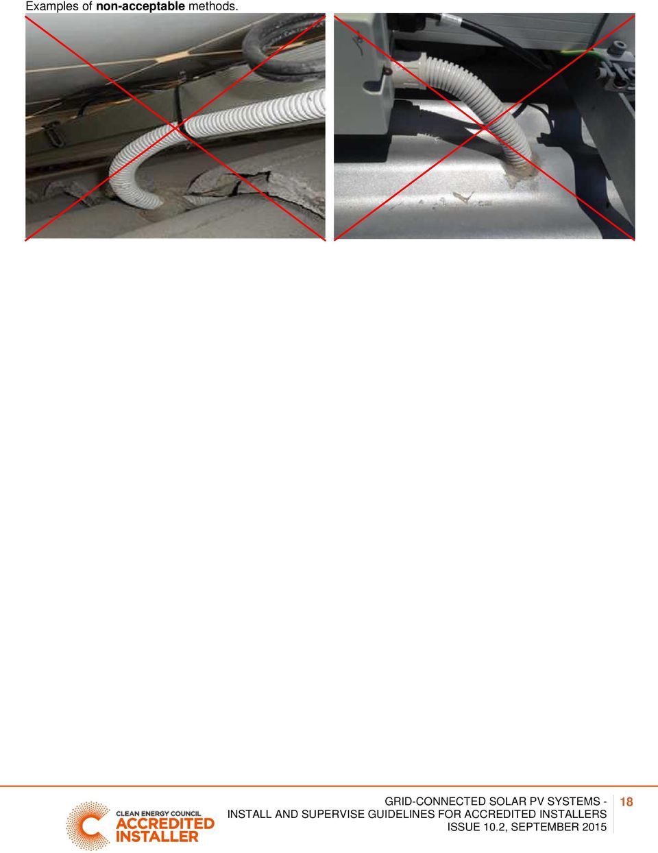
17 Conduits shall be installed so that they are adequately supported. These are examples of conduit that is not adequately supported AS/NZS5033:2014 does not allow for any medium duty (MD) conduit to be installed in the ceiling space. Ensure that the transition from MD to HD occurs at the point of penetration of the roof. Alternatively, UV rated HD corrugated conduit could be used where the cable enters the ceiling space Double insulation of each conductor shall be maintained within wiring enclosures (e.g. conduit) The wiring enclosure shall be labelled SOLAR at not more than 2m intervals Where the PV array cable and conduit passes through a tile or steel roof an appropriate collar flashing shall be installed (e.g. dectite). Note: Grinding a tile and passing the conduit between tiles is not an acceptable method as it is in breach of AS/NZS 3000 (clause ) Conduit passing through a hole in a steel roof and then sealed with silicon is in breach of Standards Australia Handbook (clause 8.6) GRID-CONNECTED SOLAR PV SYSTEMS 17

18 Examples of non-acceptable methods. 18
19 8 INVERTER INSTALLATION The inverter shall be installed in accordance with the manufacturer s instructions. The installer shall do the following: ensure the location is appropriate for the IP Rating of the inverter. Where this is not possible, then the inverter/s should be in an appropriate weatherproof enclosure comply with specific environmental requirements e.g. not exposed to direct sunlight, direct rain, etc ensure mounting structure is able to support inverter weight ensure mounting structure material is appropriate for the inverter recommended clearances around the inverter shall be followed The inverter heat sink shall be clear of any obstacles to facilitate cooling of the inverter Cables connected to the inverter shall be mechanically secured in such a manner that they cannot be inadvertently unplugged from the inverter. This can be achieved by: installing the inverter in an external enclosure (with cables suitably supported) the use of an inverter which has the cable connection area of inverter covered by a removable enclosure/cover which protects the supported cables so that there are no exposed, unsupported cable loops the use of conduit and secure wall fixings. Note: Where the inverter requires DC connectors to be used, a maximum allowable distance of no more than 300mm of unprotected DC cable shall be permitted between connectors and conduit, provided the location is not subject to mechanical damage Where the inverter is exposed to the weather there shall be no open ends of conduit. If a cable is required to exit from a conduit, an appropriate cable gland shall be installed on the end of the conduit to ensure the IP rating is maintained (see section The installer shall ensure that the inverter is configured for Australia, and that the AS4777 parameters are loaded The installer shall ensure that the grid parameters of the inverter are set to the local distributor s requirements. 19

20 8.2 PV array DC isolator near inverter (Not applicable for micro inverter AC and modules systems) Where the inverter in LV systems is not in sight of the array or more than 3m from the array, PV array switch-disconnector/s shall also be installed adjacent to the inverter. Note: Generally the PV array DC isolator at the inverter will always be required for roof top mounted systems All PV array switch-disconnectors shall be readily available (see section for details on readily available) For inverters with an integrated switch-disconnector: a separate switch-disconnector is not required at the inverter if the switch-disconnector is mechanically interlocked with a replaceable module of the inverter and allows the module to be removed from the section containing the switch-disconnector without risk of electrical hazards Where multiple disconnection devices are required to isolate power conversion equipment, they shall be grouped so that they all operate simultaneously, or they shall all be grouped in a common location and have warning signs indicating the need to isolate multiple supplies to isolate the equipment (see section 12 for examples of signs) Where there are more than one isolator, they shall be individually labelled e.g. PV Array DC isolator inverter 1 MPPT A The shutdown procedure shall align with the labelling of multiple isolators see the example below. 20

21 8.2.5 Where strings are paralleled at the inverter, the CEC recommend that this should occur on the inverter side of the disconnection devices, or in the inverter itself. Note: This will enable the cable to either string to be safely de-energised, without the need to turn off both rooftop isolators Where the inverter and isolator are exposed to the weather the isolator shall have an IP rating of at least IP 55, (Note: the CEC recommend using isolators rated to IP66) Where an isolator is exposed to the weather, the CEC recommend that there be no top entries into the isolator, and drip loops are utilised at the bottom of the isolator to minimise water ingress. Conduit entry at bottom of isolator drip loop PV array isolators shall meet the requirements of to AC isolator near inverter The purpose of the AC isolator is to de-energise the inverter for maintenance or fault rectification. 21
22 8.3.1 Where the inverter is not adjacent to the switchboard to which it is connected, an isolator shall be provided at the inverter so that a person operating the switch has a clear view of any person working on the inverter - refer to AS/NZS Connection of a.c. and d.c. components in the same enclosure shall not be mounted on a common conductive mounting rail A.c. and d.c. circuits within enclosures shall be physically segregated by an insulation barrier (see AS/NZS 5033:2014 clause ). Note: this is to reduce the chance of a.c. and d.c. cables coming in to contact with each other Where the inverter and isolator are exposed to the weather the isolator shall have an IP rating of at least IP 55, (Note: the CEC recommend using isolators rated to IP66) Where an isolator is exposed to the weather,, the CEC recommend that there be no top entries into the isolator and drip loops should be utilised at the bottom of the isolator to minimise water ingress. Conduit entry at bottom of isolator drip loop Micro inverter installation A labelled, lockable, isolating switch (inverter a.c. isolator) shall be installed at the point of transition from micro inverter interconnect cable to fixed wiring. The purpose of the a.c. isolator is to deenergise the a.c. from the micro inverter for maintenance or fault rectification The isolator shall be installed adjacent to the inverter or inverter group. This isolator may be a single isolator and can be used to isolate multiple adjacent inverters Where micro inverters are not installed adjacent to each other, additional isolators shall be installed Isolator enclosures shall be IP55 rated (CEC recommend IP66) All entry points (conduit and cable glands) to the isolator should be on the lower end of the enclosure - either underneath or facing down the roof. 8.4 AC cable selection AC cables shall comply with the wiring requirements of AS/NZS Individual states and territories may have their own specific requirements regarding cable selection and voltage rise. The installer shall ensure these are complied with Where this is not defined, it is recommended that the voltage drop between the inverter and the main switchboard should be kept as small as possible (recommended <1%) to minimise voltage rise within the installation See table below). Note: This will limit inverter disconnection in areas where the grid voltage may be high, to decrease incidents of overvoltage trips for inverters. This is also an issue for micro inverter installations where the AC cable run may be long. 22
23 Maximum Cable Lengths for 1% Voltage Rise Inverter Configuration Single Three Phase Three Phase Phase Inverter Rating (kw) Conductor Current (A) Cable Conductor Size (mm2) Conductor Material Maximum Route length Maximum Route length (m) (m) 6 Cu Cu Cu Cu Maximum Route length (m) The inverter shall be connected by fixed wiring to a dedicated circuit on a switchboard AC cables between the inverter and any switchboard and all the cables between any distribution boards and a main switchboard which carry current from the inverter shall be rated for at least the full output current of the inverter energy system All cabling shall be sized in accordance with AS/NZS 3000 and AS/NZS Solar supply main switch in switchboard The inverter should be connected directly to the main switchboard Where this is not possible or not desirable, the inverter energy system should be connected to the distribution board located physically nearest to the inverter, and the main switchboard. All intermediate distribution boards shall be appropriately labelled (see section 12 for examples of signs) Labelled Solar Supply Main Switch The main switch for the switchboard, to which the inverter is connected, shall be a lockable switch An RCD is not to be placed between the consumer s mains and the inverter. Note: Some sub-mains may be connected to the main switchboard via an RCD in lieu of mechanical protection (See Clause AS/NSZ ). If this is the case an inverter cannot be connected to that sub main due to the connection of the RCD In accordance with AS/NZS 3000, the cable between the switchboard and inverter requires protection so it is recommended that the isolator is a suitably rated circuit breaker. 8.6 Shutdown procedure A shutdown procedure is required to ensure safe de-energisation of the system The shutdown procedure shall reflect the specific requirements of the individual system. All isolating switches referred to in the shutdown procedure shall correspond to individual isolator labels. E.g PV array DC isolator, Solar Supply Main Switch For central inverter systems, an engraved label showing the shutdown procedure shall be installed adjacent to the inverter. An example shutdown procedure would be as follows: Turn off the main switch solar supply at the AC switchboard and then the AC isolator at the inverter (where installed) then Turn off the PV array isolator at the inverter. 23
24 WARNING: PV array DC isolators do not de-energise the PV array and array cabling. (see below for example) Micro inverter and AC module systems (shall be installed at the switchboard to which the inverter is connected) An example shutdown procedure would be: Turn off the main switch solar supply at the AC switchboard This will isolate the PV array DC Conditioning Units The shutdown procedure must reflect the specific requirements of the individual system. Note: As this is different for the various technologies an example cannot be given 8.7 Additional Requirements for Micro Inverters The following is in addition to the above requirements for all inverters Each input of the micro inverter is limited to 350W PV power at STC and at ELV DC cable length is less than 1.5m (including any adaptor cables) The method of cable support for the interconnecting AC cable and DC panel cables shall have a life as long as the system Cable support shall ensure that there is no stress placed on connectors Plugs, sockets and connectors shall only be mated with those of the same type from the same manufacturer A PV array disconnection device is not required for PV modules connected to micro inverters (AS/NZS 5033:2014 clause ) Note: See section 7 for array earthing requirements for micro inverter systems. 8.8 Inverter Earth Fault Indication As of 11 July 2015 AS/NZS 5033 requires the installation of an earth fault alarm indication Where the PV array maximum voltage is greater than ELV an earth fault system shall be installed The alarm system may be an audible signal, indicator light or another form of fault communication, e.g. fax, , SMS. The fault indication shall be installed in a way that it will make the system owner aware of the fault and initiate an action to correct an earth fault Micro inverter and a.c. module systems operate at with a PV array maximum voltage in the ELV range and therefore are not required to have the earth fault indication, although the CEC recommends that if the system has the capability it should be installed Where the system utilises remote monitoring to inform the customer of an earth fault the configuration of the remote monitoring shall be provided in the customer manual (see section 5). 24
25 9 METERING The installer shall notify the customer of the metering processes The system shall not be energized until correct metering is installed, other than for testing or commissioning purposes as defined in section 12. Note: AS/NZS3000 clause states that the system may not be energised until a formal agreement has been made with the electricity distributor. 10 SIGNAGE All signage on switches, isolators and within distribution boards and switchboards shall be in accordance with AS 4777 and AS/NZS 5033 and/or: The relevant electrical service and installation rules for the state where the system is installed Where multiple systems are installed at one premises, labelling shall accurately reflect which devices control which equipment See section 12 for examples of signs. 11 COMMISSIONING The commissioning sheets provided with these guidelines (or similar document) shall be completed by the accredited installer or the accredited supervisor (with suitably licensed person) A fully completed copy shall be provided to the customer in the system documentation and a copy shall be retained by the accredited person. Note: It is vitally important that a system is tested as per the commissioning requirements of this document to ensure it is safe at the time of final sign off. Additionally, it enables the installer to prove the system was correctly installed at the time of installation should any questions arise post installation. 25
26 12 INSTALLATION AND COMMISSIONING 12.1 General WARNING: Where short circuit current measurements are required, follow AS/NZS 5033 Appendix D for the steps that shall be undertaken to measure the short circuit current safely. NOTE: Some projects require that short circuit currents are recorded as part of the contractual commissioning; otherwise a record of the actual operating current of each string is sufficient. This could be done by using the meter on the inverter or by using a clamp meter when the system is operational Insulation resistance measurement WARNING: PV array dc circuits are live during daylight and, unlike a conventional ac circuit, cannot be isolated before performing this test. Follow AS/NZS 5033 Appendix D4 for the steps that shall be undertaken to measure the insulation resistance safely String Inverter Installation and commissioning sample INSTALLATION DETAILS Address of installation: PV module manufacturer and model number: Number of modules in series in a string: Inverter manufacturer and model number: Number of inverters: PV ARRAY Number of strings in parallel in PV array: Number of MPPTs: PV array tilt PV array orientation Array frame is certified to AS for Array frame is installed to manufacturer s installation location instructions No galvanically dissimilar metals are in contact Roof penetrations are suitably sealed and with the array frames or supports weatherproofed PV wiring losses are less than 3%at the Where PV array comprises multiple strings- string maximum current output of the array protection has been provided Wiring is protected from mechanical damage Weatherproof PV array isolator mounted adjacent to and is appropriately supported the array (Brand / Model:..Rating:..Vdc,.Adc) LV DC and AC INSTALLATION All low voltage wiring has been installed by a licensed electrical tradesperson All wiring has been tested and approved by qualified electrical tradesperson 26
27 INVERTER PV array isolator mounted adjacent to the inverter (Brand / Model:..Rating:..Vdc,.Adc) Lockable AC circuit breaker mounted within the switchboard to act as the inverter main switch for the PV/inverter system (Rating.. A ) Inverter ceases supplying power within two seconds of a loss of AC mains CONTINUITY CHECK Circuit checked (record a description of the circuit checked in this column) Continuity of all string, sub-array and array cables Continuity of all earth connections (including module frame) Isolator is mounted on output of the inverter (where required) Inverter is installed as per manufacturer s specification Inverter does not resume supplying power until mains have been present for more than 60 seconds. SYSTEM CHECK WARNING: IF A STRING IS REVERSED AND CONNECTED TO OTHERS, FIRE MAY RESULT. IF POLARITY IS REVERSED AT THE INVERTER DAMAGE MAY OCCUR TO THE INVERTER. Polarity Voltage Short Circuit Operating Current String 1 V A A String 2 V A A String 3 V A A String 4 V A A Sub-arrays where required V A A PV array at PV array switch-disconnector V A A Irradiance at time of recording the current W/m2 W/m2 INSULATION RESISTANCE MEASUREMENTS (see table for minimum values of insulation resistance) Array positive to earth MΩ Array negative to earth MΩ INSTALLER INFORMATION CEC Accredited installer s name: CEC Accreditation number: I verify that the above system has been installed to all relevant standards Signed: Date: CEC Accredited Designer s name: Licensed electrician s name: (where applicable, e.g. LV work) Electrician s licence number: Signed: Date: SIGNAGE (AS 4777) 27
28 On switchboard to which inverter is directly connected is permanently fixed at the main switch is permanently fixed at the solar main switch If the solar system is connected to a distribution board then the following sign is located on main switchboard and all intermediate distribution boards Where the inverter is not adjacent to the main switchboard, location information is provided SIGNAGE (AS/NZS 5033) Is permanently fixed on array junction boxes (black on yellow) Fire emergency information is permanently fixed on the main switchboard and/or meter box (if not installed together) PV DC isolation is clearly identified SHUTDOWN PROCEDURE INSERT APPROPRIATE STEPS FOR SAFE SHUTDOWN. Shutdown procedure is permanently fixed at inverter and/or on main switchboard Is placed adjacent to the inverter when multiple isolation/disconnection devices are used that are not ganged together Exterior surface of wiring enclosures labelled SOLAR at 2 m intervals Any other signage as required by the local electricity distributor WARNING PV ARRAY D.C. ISOLATORS DO NOT DE-ENERGIZE THE PV ARRAY AND ARRAY CABLINGS Table Minimum insulation resistance 28
29 12.4 Micro Inverter and AC Module Installation and commissioning sample INSTALLATION DETAILS Address of installation: PV module manufacturer and model number: Number of modules in array: Inverter manufacturer and model number: Number of inverters: PV ARRAY PV array 1 tilt PV array 1 orientation.. Number of panels PV array 2 tilt PV array 2 orientation.. Number of panels PV array 3 tilt PV array 3 orientation.. Number of panels PV array 4 tilt PV array 4 orientation.. Number of panels Array frame is certified to AS for installation Array frame is installed to manufacturer s instructions location Wiring is protected from mechanical damage and is appropriately supported Roof penetrations are suitably sealed and weatherproofed LV DC and AC INSTALLATION All low voltage wiring has been installed by a licensed electrical tradesperson No galvanically dissimilar metals are in contact with the array frames or supports All wiring has been tested and approved by qualified electrical tradesperson 29
Electrical safety of grid-connected solar installations in Western Australia December 2011
 Electrical safety of grid-connected solar installations in Western Australia December 2011 Level 1, 303 Sevenoaks Street (cnr Grose Avenue) Cannington, Western Australia 6107 PO Box 135 Cannington WA 6987
Listed are common requirements that apply to existing solar installations when altered, added to or reconfigured.
 SOLAR ALTERATIONS REQUIREMENTS August 2015 These requirements address typical alterations to solar installations; they cannot address every scenario. In Victoria, an alteration to a solar installation
12 SOLAR PHOTOVOLTAIC POWER SUPPLY SYSTEMS by John Ware. PV modules are current-limiting
 12 SOLAR PHOTOVOLTAIC POWER by John Ware IT IS PLANNED for BS 7671:2008 to include a new Section 712 providing additional requirements for safety applicable to solar photovoltaic (pv) power supply systems.
Solar Panel Installations
 Solar Panel Installations Page 1 of 6 SINGLE-FAMILY RESIDENTIAL CHECKLIST City of Hayward Development Services Department Revised: 7-09-15 PERMIT REQUIREMENTS Permits are required for all solar panel installations.
What are the basic electrical safety issues and remedies in solar photovoltaic installations?
 What are the basic electrical safety issues and remedies in solar photovoltaic installations? Presented by: Behzad Eghtesady City of Los Angeles Department of Building and Safety Topics Covered Photovoltaic
How To Plan Out An Array Of Solar Panels
 CITY OF DOWNEY COMMUNITY DEVELOPMENT, BUILDING AND SAFETY 11111 Brookshire Avenue Downey, CA 90241 562.904.7142 (www.downeyca.org) B SECTION 01/01/2011 EFFECTIVE DATE PHOTOVOLTAIC 032 FORM NUMBER 2013
White Paper SolarEdge Three Phase Inverter System Design and the National Electrical Code. June 2015 Revision 1.5
 White Paper SolarEdge Three Phase Inverter System Design and the National Electrical Code June 2015 Revision 1.5 Shalhevet Bar-Asher; SolarEdge Technologies, Inc. Bill Brooks, PE; Brooks Engineering LLC
INSTALLATION GUIDELINES for SOLAR PHOTOVOLTAIC SYSTEMS 1
 City of Cotati Building Division 201 W. Sierra Ave. Cotati, CA 94931 707 665-3637 Fax 792-4604 INSTALLATION GUIDELINES for SOLAR PHOTOVOLTAIC SYSTEMS 1 Any PV system on a new structures should be included
2011/2008/2005 NATIONAL ELECTRICAL CODE SOLAR PV CODE COMPLIANCE REFERENCE
 2011/2008/2005 NATIONAL ELECTRICAL CODE SOLAR PV CODE COMPLIANCE REFERENCE PAGE 1 OF 5 This Reference provides a very comprehensive list of aspects of a solar PV installation that could be reviewed, clarifying
Installation Guide of Sunrise Solartech PV Modules. Term 2013. Contents. Purpose of this guide. General. Safety precaution for installing a solar
 Installation Guide of Sunrise Solartech PV Modules Term 2013 Contents Purpose of this guide General Safety precaution for installing a solar Photovoltaic system Product Identification Mechanical Installation
SOLAR PV STANDARD ELECTRICAL PLAN Microinverter Systems for Single Family Dwellings
 *** Provide this document to the inspector along with ALL system installation instructions *** Project Address: Scope: Standard plan for the installation of grounded microinverter solar PV systems, not
Trial Exams C. Standards and Regulations. Examination No: GH-08-C- 1 hour and 5 minutes plus 10 minutes reading time
 Trial Exams C Standards and Regulations Examination No: GH-08-C- This test is intended to gauge your knowledge of essential information contained within AS/CA S009:2013. To qualify for an allpication to
FAQs-Main switchboard design criteria
 FAQs-Main switchboard design criteria Q: What is the Australian standard for main switchboards? Current Australian standard is AS/NZS 3439.1: 2002 originating from IEC 60439. The new series of standard
GENERAL INSTALLATION MANUAL FOR EGING PV MODULES
 GENERAL INSTALLATION MANUAL FOR EGING PV MODULES PLEASE READ THIS MANUAL CAREFULLY BEFORE INSTALLING OR USING THE MODULES. PLEASE PASS ALONG THE ATTACHED USER MANUAL TO YOUR CUSTOMER. 1. INTRODUCTION This
City of Riverside Building & Safety Division Phone: (951) 826-5697 www.riversideca.gov
 826-5697 www.riversideca.gov") City of Riverside Building & Safety Division Phone: (951) 826-5697 www.riversideca.gov PHOTOVOLTAIC PERMITTING GUIDELINES The information provided in this document is general and is intended only as a
City of Riverside Building & Safety Division Phone: (951) 826-5697 www.riversideca.gov PHOTOVOLTAIC PERMITTING GUIDELINES The information provided in this document is general and is intended only as a
Ontario Electrical Safety Code 25 th Edition/ 2012
 Ontario Electrical Safety Code 25 th Edition/ 2012 Ted Olechna Director, Codes and Standard Chief Engineer 1 What I Will Cover ESA s role is as the regulator Highlight of 2012 Code changes The Code and
City of San Diego Residential Photovoltaic Systems Inspection Guidelines
 City of San Diego Residential Photovoltaic Systems Inspection Guidelines The purpose of inspections by DSD staff is to ensure compliance with the California Electrical Code (CEC), other applicable codes
YINGLI SOLAR PV MODULES Installation and User Manual
 YINGLI SOLAR PV MODULES Installation and User Manual Revision Date December 24, 2011 Applicable for IEC certified products This manual applies to photovoltaic modules ( PV modules, also commonly known
County of Riverside Building and Safety Department
 County of Riverside Building and Safety Department Mike Lara Director Photovoltaic Permitting Guidelines The information provided in this document is general and is intended only as a guide. Each project
Solar Photovoltaic (PV) Systems
 Systems") ARTICLE 690 Solar Photovoltaic (PV) Systems INTRODUCTION TO ARTICLE 690 SOLAR PHOTOVOLTAIC (PV) SYSTEMS You ve seen, or maybe own, photocell-powered devices such as night lights, car coolers, and toys.
ARTICLE 690 Solar Photovoltaic (PV) Systems INTRODUCTION TO ARTICLE 690 SOLAR PHOTOVOLTAIC (PV) SYSTEMS You ve seen, or maybe own, photocell-powered devices such as night lights, car coolers, and toys.
TECHNICAL SPECIFICATIONS
 1. Standards BOS Item / System I ii iii TECHNICAL SPECIFICATIONS Applicable BIS /Equivalent IEC Standards / Applicable MNRE Specifications Standard Description Standard Number Crystalline Silicon Terrestrial
Checklist Testing and inspection without interconnection
 Shams Dubai Checklist Testing and inspection without interconnection Version.0 AUGUST 205 TABLE OF CONTENTS Scope...5. PV PLANT AND INSPECTION DATA... 6 2 TESTING EQUIPMENT...7 3 DOCUMENTS... 8 3. Reference
TECHNICAL BRIEF. Commercial PV in Australia and New Zealand Using the Enphase Microinverter System
 TECHNICAL BRIEF Commercial PV in Australia and New Zealand Using the Enphase Microinverter System 2015 Enphase Energy Inc. All rights reserved May 2015 Table of Contents Commercial PV in Australia and
Los Angeles Fire Department Requirement No. 96 SOLAR PHOTOVOLTAIC SYSTEM
 Los Angeles Fire Department Requirement No. 96 SOLAR PHOTOVOLTAIC SYSTEM The following is the Los Angeles Fire Department s minimum requirement for Solar Photovoltaic System Installations. The City of
Doe Residence - 5.64 kw DC Roof Mounted Photovoltaic System
 EQUIPMENT SUMMARY 20 LG 300W solar panels 1 SMA SE6000AUS Inverter Everest Solar Systems Cross Rail Racking System QuickMount PV Quick Hook Curved Tile Mount QMCTH SHEET INDEX T01 COVER PV01 SITE MAP &
Electrical Practices for Construction Work
 1. Purpose Electrical Practices for Construction Work The purpose of this Code is to provide practical guidance and set minimum safety requirements for electrical practices on all construction sites in
CHECKING AND TESTING ELECTRICAL INSTALLING WORK
 CHECKING AND TESTING ELECTRICAL INSTALLING WORK Department of Consumer and Employment Protection Energy Safety Preface It is a requirement of the Electricity (Licensing) Regulations 1991 that all electrical
ADDENDUM #1(BID PACKAGE # 3)
") H2Engineering, Inc. 114 East Fifth Avenue Tallahassee, FL 32303 Phone 850.224.7922 Fax 850.224.5876 ADDENDUM #1(BID PACKAGE # 3) To: Jeff Williams From: Peter Lindstrom Co: Leon County Date: October 04,
H2Engineering, Inc. 114 East Fifth Avenue Tallahassee, FL 32303 Phone 850.224.7922 Fax 850.224.5876 ADDENDUM #1(BID PACKAGE # 3) To: Jeff Williams From: Peter Lindstrom Co: Leon County Date: October 04,
SOLAR ELECTRIC MODULE ES-124 & ES-62T Owners Manual and Installation Guide
 SOLAR ELECTRIC MODULE ES-124 & ES-62T Owners Manual and Installation Guide circuit. Reverse connection will damage the module and may result in fire. CAUTIONS Solar electric modules produce DC electricity
2012 Canadian Electrical Code, Part I (CEC) Top Fifteen changes
 Top Fifteen changes") 2012 Canadian Electrical Code, Part I (CEC) Top Fifteen changes 1) Tamper resistant receptacles. 2009 CEC Required in dwelling units 2012 CEC Expanded to child care facilities First introduced in the 2009
2012 Canadian Electrical Code, Part I (CEC) Top Fifteen changes 1) Tamper resistant receptacles. 2009 CEC Required in dwelling units 2012 CEC Expanded to child care facilities First introduced in the 2009
PV and the Electrical Code Page 1 PV and the Electrical Code
 PV and the Electrical Code Page 1 PV and the Electrical Code Canadian Solar Industries Association (CanSIA) PV and the Electrical Code Page 2 This course was prepared by the Canadian Solar Industries Association
Installation Guide Content for P250xV-240 microinverters
 A C M o d u l e Installation Guide Content for P250xV-240 microinverters May 15, 2012 2011-2012 SolarBridge Technologies, Inc. All Rights Reserved. No part of this publication may be reused in any manner
YSmart Technology Co.,Ltd
 YSmart Technology Co.,Ltd GWV Series Grid Tie Microinverter User Manual The copyright of this user manual belong to YSmart TechnologyCompany Limited. Without the written permission of the copyright holder,
Low voltage Direct Current Network. Compact NSX DC PV. Circuit breakers and switch disconnectors for solar application.
 Low voltage Direct Current Network Compact NSX DC PV Circuit breakers and switch disconnectors for solar application Catalogue 2012 Compact NSX DC PV A complete DC offer for solar application from 80
SAFETY OF SOLAR PANEL INSTALLATIONS IN VICTORIA REPORT
 SAFETY OF SOLAR PANEL INSTALLATIONS IN VICTORIA REPORT July 2010 Table of Contents Executive Summary... 3 Glossary of Acronyms and Phrases.....4 Introduction...5 Background 6 Electricity safety requirements
Safety and Installation Instructions for AC Modules
 Safety and Installation Instructions for AC Modules United States and Canada Contents of this manual are subject to change without notice. For the latest guide please refer to www.sunpower.com/pvinstallguideacmodule
Application Bulletin 103 - NEC Reference Guide for SolarBridge-Enabled AC Module Installers
 9229 Waterford Centre Dr. Bldg C, Suite 110 Austin, Tx 78758 Application Bulletin 103 - NEC Reference Guide for SolarBridge-Enabled AC Module Installers Current Version: 13 AC Modules are a new product
READ THIS MANUAL BEFORE PROCEEDING WITH THE INSTALLATION. FAILURE TO FOLLOW THE INSTALLATION INSTRUCTIONS MAY VOID YOUR WARRANTY!
 READ THIS MANUAL BEFORE PROCEEDING WITH THE INSTALLATION. FAILURE TO FOLLOW THE INSTALLATION INSTRUCTIONS MAY VOID YOUR WARRANTY! The main power to any existing system must be disconnected prior to the
PERMIT APPLICATION REQUIREMENTS FOR RESIDENTIAL ROOF MOUNTED PHOTOVOLTAIC SYSTEMS
 Butte County Department of Development Services PERMIT CENTER 7 County Center Drive, Oroville, CA 95965 Main Phone (530)538-7601 Permit Center Phone (530)538-6861 Fax (530)538-7785 FORM NO DBP-71 PERMIT
Guideline for Fire Safety Elements of Solar Photovoltaic Systems July 17, 2008 Rev: 1/1/10
 Guideline for Fire Safety Elements of Solar Photovoltaic Systems July 17, 2008 Rev: 1/1/10 This document was developed by the Orange County Fire Chiefs Association, Orange County Fire Marshal Committee.
AC Module Installation Guide Content
 AC Module Installation Guide Content for ET-P660250AC May 9, 2012 2011-2012 ET Solar Group All Rights Reserved. No part of this publication may be reused in any manner nor in any form or format without
GreenWay Solar LED Path and Trail Lighting System. Installation and Owner s Manual
 GreenWay Solar LED Path and Trail Lighting System Installation and Owner s Manual Important Notes and Warnings This installation and instruction manual provides installation, operation, and maintenance
Request for Proposals for Photovoltaic System Installation
 Request for Proposals for Photovoltaic System Installation Presented by: Prepared by: Location: Contact: Date: Capitol Hill Housing Foundation Bonneville Environmental Foundation, Renewable Energy Group
Model Number Electrical Compatibility Module Connector Type. M250-60-2LL-S22 60 cell PV module MC-4 Type 2 Locking
 TECHNICAL BRIEF M250 Microinverter System Installation Planning The M250 Microinverter The Enphase M250 Microinverter is a powerful and efficient grid-tied microinverter. It is compatible with most 60-cell
User Manual DONGGUAN SHENGYANG INDUSTRIAL CO., LTD. SY WMVC Smart Grid Tie Microinverter. Dongguan Shengyang Industrial Co., Ltd.
 DONGGUAN SHENGYANG INDUSTRIAL CO., LTD SY WMVC Smart Grid Tie Microinverter User Manual Dongguan Shengyang Industrial Co., Ltd. ADD: No. 1 Shangxin Road, New Village, Xin An Community, Chang An Town, Dongguan
Solar Power Systems Models: PVS220W-24 and PVS220W-48 Installation Manual
 Solar Power Systems Models: PVS220W-24 and PVS220W-48 Installation Manual 255379 Rev. D0 1015 Printed in U.S.A. Copyright 2015 Federal Signal Corporation Limited Warranty The Alerting and Notification
Section III Schedule of Requirements TECHNICAL SPECIFICATIONS OF THE REQUIRED SYSTEMS
 PART III TECHNICAL SPECIFICATIONS OF THE REQUIRED SYSTEMS I. GENERAL The objective of this specification is to describe a system which uses solar energy to produce electricity. For each site (lot) one
SMALL SCALE RENEWABLE ENERGY STANDARDS GUIDE
 SMALL SCALE RENEWABLE ENERGY STANDARDS GUIDE VERSION: 1.1 A guide to relevant standards in New Zealand For the design and installation of small scale renewable energy systems This guide has been produced
Advantium 2 Plus Alarm
 ADI 9510-B Advantium 2 Plus Alarm INSTALLATION AND OPERATING INSTRUCTIONS Carefully Read These Instructions Before Operating Carefully Read These Controls Corporation of America 1501 Harpers Road Virginia
Consumer guide. be brighter. actewagl.com.au/solar solar@actewagl.com.au 13 14 93
 be brighter. Consumer guide. Your guide on how solar works, how much you can save on your electricity bills and how to choose the right provider and system for you. actewagl.com.au/solar solar@actewagl.com.au
RAY-MAX Integrated Solar Power Strip
 RAY-MAX Integrated Solar Power Strip 600008, 600009, 600010, 600208, 600209, 600210 Owner s Manual NEXTRONEX, INC. Revision Date: 10/27/14 Contents 1. Safety Instructions... 3 2. General Equipment Warnings...
SA Power Networks Planning for Solar PV? Customer information guide to network connected solar PV inverter systems
 SA Power Networks Planning for Solar PV? Customer information guide to network connected solar PV inverter systems Contents Introduction 3 How solar PV power systems work 4 Solar modules 5 Is solar power
SOLARCARE SERIES PRODUCT AND APPLICATION GUIDE
 SOLARCARE SERIES PRODUCT AND APPLICATION GUIDE for solar energy management LEATEC Delivering Solutions for Energy Management SOLAR ENERGY DATA CENTER BUILDING 4 to8 String Monitoring with 0.% Accuracy
AS/NZS 3000:2007 Amendment 2
 AS/NZS 3000:2007 Amendment 2 Published 14 December 2012 Under Victorian legislation the day a revised standard is published it becomes the requirement. The aim of this document is to highlight the important
Engage Coupler. Engage Coupler Chase
 TECHNICAL BRIEF Wire Management in an Enphase System The Enphase Microinverter System installs much more quickly than other PV (photovoltaic) system technologies. This is partly due to the plug-and-play
Unified requirements for systems with voltages above 1 kv up to 15 kv
 (1991) (Rev.1 May 2001) (Rev.2 July 2003) (Rev.3 Feb 2015) Unified requirements for systems with voltages above 1 kv up to 15 kv 1. General 1.1 Field of application The following requirements apply to
LEHI CITY POWER NET METERING STANDARDS For Customer-Owned Electric Generating Systems
 LEHI CITY POWER NET METERING STANDARDS For Customer-Owned Electric Generating Systems A. General This Net Metering Standard for Customer-Owned Grid Connected Electric Generating Systems sets forth the
Photovoltaic System Overcurrent Protection
 Photovoltaic System Overcurrent Protection Photovoltaic System Overcurrent Protection Introduction Solar Photovoltaic (PV) systems have, over the last fifty years, evolved into a mature, sustainable and
SHARP SOLAR Frequently Asked Questions for PV Integrators Revised 05/04/2010
 SHARP SOLAR Frequently Asked Questions for PV Integrators Revised 05/04/2010 How do I determine the PTC rating of a module? PTC refers to PVUSA Test Conditions, which were developed to test and compare
D. Infrared scanning reports with pictures printed in a final report with any deficiencies and actions taken to rectify.
 SECTION 263354 STATIC UPS TESTING AND COMMISSIONING PART 1 - GENERAL 1.1 SUMMARY A. Section Includes 1. System start-up services. 2. Battery charging. 3. Load bank testing. 4. Battery load testing. 5.
GROWTH MANAGEMENT DEPARTMENT 201 SE 3 rd ST, (Second Floor), Ocala, FL 34471 (352) 629-8421; FAX: (352) 629-8264
, Ocala, FL 34471 (352) 629-8421; FAX: (352) 629-8264") BUILDING CODE GUIDELINES FOR ELECTRICAL INSPECTIONS Building Code compliance is the obligation of design professionals and/or contractors. Plan Review and Inspection Guidelines are intended to be used
BUILDING CODE GUIDELINES FOR ELECTRICAL INSPECTIONS Building Code compliance is the obligation of design professionals and/or contractors. Plan Review and Inspection Guidelines are intended to be used
Solar Kit. Complete solution to optimize your photovoltaic system
 Solar Kit Complete solution to optimize your photovoltaic system April 2012 Mounting and selection quick guide On Grid Solar Kit rooftop installation INSTALLATION WITH OVERLAID SUB-STRUCTURE (A.1, A.2)
Enphase Microinverter Model M215
 INSTALLATION AND OPERATION MANUAL Enphase Microinverter Model M215 (M215-60-230) 141-00017, Rev 02c Corporate Headquarters Contact Information Enphase Energy Inc. 1420 N. McDowell Blvd. Petaluma, CA 94954
Union County Public Schools. Facilities Department. Electrical. Safe Work Practices
 1 Union County Public Schools Facilities Department Electrical Safe Work Practices 2 Purpose In accordance with OSHA Standards 1910.331-335, safety-related work practices shall be used by Union County
ELECTRICAL INSULATION TESTING OF HV EQUIPMENT UP TO 33kV
 1. SCOPE This document details PowerSystems requirements for electrical testing of HV Equipment up to and including 33kV. 2. ISSUE RECORD This is a Reference document. The current version of Controlled
Installation Guide Solar Connect-11
 Installation Guide Solar Connect-11 Version 1.1 Contents Important Product Information 3 System Registration Form 4 Solar Connect-11 Overview 5 Internet & Power Connections 6 Single Phase CT Connections
Outdoor 33.6W Dual Port Passive Power-over-Ethernet Midspan For External Security Cameras and Wireless Access Points
 Outdoor 33.6W Dual Port Passive Power-over-Ethernet Midspan For External Security Cameras and Wireless Access Points Features SELV Compliant No Detection Passive Injector Gigabit Compatible Full Protection
Contractor Connect Scheme Electrical Contractor and Worker Handbook
 Contractor Connect Scheme Electrical Contractor and Worker Handbook January 2016 Document release information Document number 13553681 Document title Revision status Contractor Connect Scheme handbook
AVAILABLE TO DOWNLOAD ON THE APOLLO APP. Fire Alarm Systems Design. a guide to BS5839
 AVAILABLE TO DOWNLOAD ON THE APOLLO APP a guide to Fire Alarm Systems Design BS5839 Part1:2013 The Regulatory Reform (Fire Safety) Order (FSO) became law on 1 October 2006 Legally you must comply! What
INFRARED QUARTZ WALL HEATER
 INFRARED QUARTZ WALL HEATER MODEL NO: IQ2000 PART NO: 6939004 MOUNTING & OPERATION INSTRUCTIONS GC0715 INTRODUCTION Thank you for purchasing this CLARKE Infrared Wall Heater. Before attempting to use this
HOW TO CORRECTLY CONNECT DEEP CYCLE BATTERIES AND CHOOSE THE RIGHT CABLE SIZING
 HOW TO CORRECTLY CONNECT DEEP CYCLE BATTERIES AND CHOOSE THE RIGHT CABLE SIZING There are several ways to wire multiple batteries to achieve the correct battery voltage or capacity for a particular DC
Installation and operating instructions. Solar charge controller Solarix MPPT 2010 730927 Z03 1242 730927 Z03 1242
 Installation and operating instructions Solar charge controller Solarix MPPT 2010 EN 730927 Z03 1242 730927 Z03 1242 1 Contents 1. About these instructions...3 1.1 Applicability...3 1.2 Users...3 1.3.
ELECTRICAL PRACTICES FOR CONSTRUCTION WORK
 CONTRACTOR S CHECKLIST ELECTRICAL PRACTICES FOR CONSTRUCTION WORK 2007 WorkCover. Watching out for you. New South Wales Government Disclaimer This publication contains information regarding occupational
All work must conform to the National Electric Code, latest edition, and all other applicable codes and regulations.
 DIVISION 16 ELECTRICAL SECTION 16100 - ELECTRICAL PART 1 - GENERAL SCOPE All electrical work as shown on the drawings and as necessary to provide a complete electrical system. Include primary service,
TIG INVERTER INSTRUCTION MANUAL
 TIG INVERTER INSTRUCTION MANUAL Contents Warning General Description Block Diagram Main Parameters Circuit Diagram Installation and Operation Caution Maintenance Spare Parts List Troubleshooting 3 4 4
Heading FACT SHEET. Overview. www.safeworkaustralia.gov.au
 ELECTRICAL RISKS AT THE WORKPLACE Heading FACT SHEET Overview This fact sheet provides general guidance for persons conducting a business or undertaking (PCBUs) and workers on managing electrical risks
RESIDENTIAL PHOTOVOLTAIC SUBMITTAL REQUIREMENTS
 DEVELOPMENT AND RESOURCE MANAGEMENT DEPARTMENT BUILDING AND SAFETY SERVICES 2600 Fresno Street, Third Floor Fresno, California 93721-3604 (559) 621-8082 FAX (559) 498-4357 RESIDENTIAL PHOTOVOLTAIC SUBMITTAL
TruPower-Portable-500W. Solar Starter kit
 TruPower-Portable-500W Solar Starter kit This Solar starter kit is an easy to use solar power supply system that is the complete solution for all your solar power needs. It is a solar generator that converts
Electrical for Detached Garages: Updated Feb 19, 2016 for 2015 CE Code in force Jan. 1, 2016. Underground branch circuit feeding a detached garage:
 Electrical for Detached Garages: Updated Feb 19, 2016 for 2015 CE Code in force Jan. 1, 2016 * Garage construction requires permits (electrical, building) * Permits must be applied for at the time. * Dial
DRM75A 230V 20/100A DIN rail single phase two wire energy meter
 DRM75A 230V 20/100A DIN rail single phase two wire energy meter 1.1 Safety instruction 1.2 Foreword 1.3 Performance criteria 1.4 Specifications 1.5 Basic errors 1.6 Description 1.7 Dimensions 1.8 Installation
Enphase Microinverters and Ungrounded Renewable Energy Systems: Canadian Electrical Code Compliance
 WHITE PAPER Enphase Microinverters and Ungrounded Renewable Energy Systems: Canadian Electrical Code Compliance Overview Enphase has developed a new microinverter family that includes the M250 and new
3.1.1 Full Type Tests & Routine Tests according to Clause 8 2 & 8 3. 4.0 Instructions For Installation, Operation & Maintenance
 SPECIFICATION FOR LOW VOLTAGE SWITCHBOARD SEN I N D E X Description 10 STANDARD TECHNICAL REQUIREMENTS 11 Standards 12 General Operating Conditions 13 General Description Of Switchboard 131 Structure 132
Photovoltaics in Buildings
 Photovoltaics in Buildings Guide to the installation of PV systems 2nd Edition the department for Enterprise DTI/Pub URN 06/1972 Preface to 2nd edition 2006 Since the first edition (2002) the guide has
Solar Home System. User Manual. AEH-SHS01-10W2L Solar Home System 2 Lamps
 Solar Home System User Manual AEHSHS0110W2L Solar Home System 2 Lamps All rights reserved Specifications subject to change without prior notice 2 Dear Customer, Thank you for purchasing Schneider Electric
INTRODUCTION WARNING S!!! VOC SHOULD BE BETWEEN 78 95. MUST NOT EXCEED 96 VOC USE DC CIRCUIT BREAKER/ISOLATOR BETWEEN SOLAR PANELS & CONTROLLER
 INTRODUCTION Thank you for purchasing a WATERBOY pumping system. We set the standard for quality and economy in solar pumping. The WATERBOY range incorporates the best solar pump technologies that were
33.6W Power over Ethernet Waterproof Adapter PoE Plus Single Port Injector for Outdoor Application
 33.6W Power over Ethernet Waterproof Adapter PoE Plus Single Port Injector for Outdoor Application Features Compliant with the IEEE802.3at Standard -40 to +60 C Temperature Range Diagnostic LEDs Full Protection
Solar Power System Installation Manual
 Solar Power System Installation Manual Power-Save Energy Co. 3940-7 Broad St. #200 San Luis Obispo, CA 93401 866 297 7192 FOR INSTALLATION PERSONNEL Please read this manual carefully before installing
Ducoterra Radiant Heating Panel Installation Manual
 Ducoterra Radiant Heating Panel Installation Manual 1. Introduction Your new radiant heating panels are designed to heat living and working spaces rapidly and efficiently by radiant heating. Like the sun,
MIC-WKT and MIC-WKT-IR
 MIC-WKT and MIC-WKT-IR Installation Manual Bosch Security Systems EN Installation and Operation Manual MIC-WKTI and MIC-WKT-IR Installation Manual EN 2 MIC-WKT and MIC-WKT-IR Washer Pump Drive Card Kits
User Manual SG30KTL-M PV Grid-Connected Inverter
 User Manual SG30KTL-M PV Grid-Connected Inverter SG30KTL-MV2-UEN-Ver22-201503 Version: 2.2 About This Manual This manual is for the inverter SG30KTL-M. The inverter is grid-connected, transformer-less,
MTE SERIES RLW. World REACTORS USER MANUAL PART NO. INSTR 030 REL. 090930. 2009 MTE Corporation
 MTE SERIES RLW World REACTORS USER MANUAL PART NO. INSTR 030 REL. 090930 2009 MTE Corporation IMPORTANT USER INFORMATION NOTICE MTE Series RLW reactors are components designed to improve the reliability
LS1024B / LS2024B/ LS3024B. Solar Charge Controller USER MANUAL
 EPSOLAR LS1024B / LS2024B/ LS3024B Solar Charge Controller USER MANUAL Thank you very much for selecting our product! This manual offers important information and suggestions with respect to installation,
DOMESTIC ELECTRICAL INSTALLATION CERTIFICATE (Requirements for Electrical Installations BS 7671 IEE Wiring Regulations)
") DOMESTIC ELECTRICAL INSTALLATION CERTIFICATE (Requirements for Electrical Installations BS 7671 IEE Wiring Regulations) DETAILS OF THE CLEINT Client and address ADDRESS OF THE INSTALLATION Installation
DOMESTIC ELECTRICAL INSTALLATION CERTIFICATE (Requirements for Electrical Installations BS 7671 IEE Wiring Regulations) DETAILS OF THE CLEINT Client and address ADDRESS OF THE INSTALLATION Installation
BEST PRACTICE REGULATION OF THE AUSTRALIAN SOLAR INDUSTRY CLEAN ENERGY COUNCIL FEBRUARY 2015
 BEST PRACTICE REGULATION OF THE AUSTRALIAN SOLAR INDUSTRY CLEAN ENERGY COUNCIL FEBRUARY 2015 1 This paper outlines the current regulatory framework for the Australian solar industry, and the range of initiatives
MISCELLANEOUS ELECTRICAL JOBS REQUIRING PERMITS
 MISCELLANEOUS ELECTRICAL JOBS REQUIRING PERMITS 01. SAFETY INSPECTION of service equipment at FPL Power Source 02. Construction GFI power outlets (Temp Pole for Construction) 03. 90 day temporary power
Using the sun to generate electricity
 Using the sun to generate electricity Image source: http://www.globalsolarcenter.com/files/2009/04/commercial-solar.jpg Solar panels information sheet What are the benefits? How does it work? What is the
Fire. The Fire Installers Mate. A guide to fire alarm systems design
 Fire The Fire Installers Mate A guide to fire alarm systems design BS 5839 Part 1:2002 A guide to BS 5839 Part 1:2002 Disclaimer This booklet is not intended to be a comprehensive guide to all aspects
ESP 120 M1, ESP 208 M1, ESP 240 M1, ESP 415 M1, ESP 277 M1, ESP 480 M1 and M1R variants. Installation instructions ESP M1/M1R mains protectors
 ESP 120 M1, ESP 208 M1, ESP 240 M1, ESP 415 M1, ESP 277 M1, ESP 480 M1 and M1R variants Installation instructions Contents Key points of installation Before installation Installation Installation check
Enphase Engage Cable and Accessories
 INSTALLATION MANUAL Enphase Engage Cable and Accessories 141-00016, Rev 03 Corporate Headquarters Contact Information Enphase Energy Inc. 1420 N. McDowell Blvd. Petaluma, CA 94954 USA Phone: +1 707-763-4784
ST Series POWER SUPPLIES USER INSTRUCTIONS
 Introduction These instructions detail the installation and operation requirements for the ST20 & ST35 power supplies. These have been designed for operation in RV s providing a DC power system, with optional