FOM-5A, 6A. Asynchronous Fiber Optic Modem
|
|
|
- Frederick Porter
- 9 years ago
- Views:
Transcription
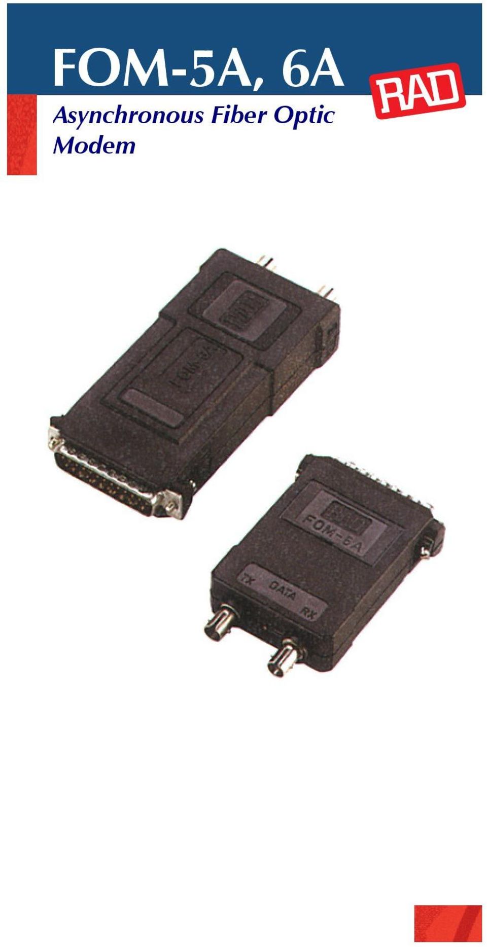
1 FOM-5A, 6A Asynchronous Fiber Optic Modem
2 FEATURES Asynchronous transmission at up to 19.2 kbps Transmission range up to 3 km (1.8 mi), regardless of data rate Full- or half-duplex Transfers one control signal end-to-end DCE-DTE switch No external power required Plugs directly into V.24/RS-232 terminal connector LED indicator for transmit data Compact, lightweight, easy to install APPLICATION

3 DESCRIPTION FOM-5A and FOM-6A are asynchronous fiber optic modems that are used for local data distribution to connect full- or half-duplex async computers and terminals. A pair of modems ensures integrity of data transmission over fiber optic cable at distances of up to 3 km (1.8 mi). FOM-5A is a miniature version of FOM-6A. Both modems are fully compatible and offer the same features. FOM-5A is 78 mm (3.1 in) by 18 mm (0.7 in); FOM-6A is 110 mm (4.3 in) by 24 mm (0.9 in). FOM-5A and FOM-6A feature a switch-selectable DTE/DCE option. This allows operation as DTE for connection to a DCE, such as a multiplexer port, eliminating the need for a cross-cable. To transfer a control signal end-to-end, the carrier can be strapped for either continuous or switched operation and controlled by the RTS signal. A LED indicator lights whenever data transmission takes place. Note: In FOM-6A with the optional metal case, the LED indicator is not available.

4 The delay between Request-to-Send and Clear-to-Send can be set to 2 or 15 msec. FOM-5A and FOM-6A operate without connection to the mains supply, by using ultra-low power from the data and control signals. Both modems are supplied in a plastic case. FOM-6A can be ordered with an optional metal case to reduce radiated emission (see Ordering). FOM-5A and FOM-6A provide all the advantages of a fiber optic system: Lower attenuation than copper wire Immunity to EMI/RFI and noise eliminates the cost of expensive and heavy shielding and complex error checking routines High data security reduces costs of data encryption. Negligible power radiation from the fiber makes eavesdropping virtually impossible Safety and electrical isolation: no spark hazard and no ground-loop noise problems. Note: Attenuation is not related to frequency.

5 SPECIFICATIONS Data Rate Up to 19.2 kbps Pulse Width Distortion Less than 25% Transmission Line Duplex optical cable Transmission Mode Asynchronous, full- or half-duplex Transmission Controls Carrier constantly ON or controlled by RTS Fiber Optic Interface ST or FC (see Ordering) Fiber optic characteristics: see Table 1 Operating Wavelength and Transmitter 850 nm VCSEL Table 1. Fiber Optic Characteristics Fiber Type [µm ] Optical Output [dbm] Receiver Sensitivity [dbm] Maximum Range [km mi] 50/ / / Note: 100/140 fiber does not work for distances less than 500m (0.3 mi).

6 Terminal Interface V.24/RS-232 D-type 25-pin, male or female connector (see Ordering) RTS/CTS Delay 2 or 15 msec Power For proper operation, the following pins of the DTE connector (DB-25) must be active: DCE mode: 2, 4 and 20 DTE mode: 3, 6 and 8 Typical power consumption drawn from these pins is 50 mw (at +6V signal level). Physical FOM-5A: Length: 78 mm / 3.1 in Width: 53 mm / 2.1 in Height: 18 mm / 0.7 in Weight 54 g / 1.9 oz FOM-6A: Length: 110 mm / 4.3 in Width: 53 mm / 2.1 in Height: 24 mm / 0.9 in Weight: 82 g / 2.9 oz Environment Temperature: 0 50 C/ F Humidity: Up to 90%, non-condensing
. Physical FOM-5A: Length: 78 mm / 3.1 in Width: 53 mm / 2.1 in Height: 18 mm / 0.7 in Weight 54 g / 1.9 oz FOM-6A: Length: 110 mm / 4.")
7 INSTALLATION Caution. When setting the jumpers or performing any actions inside the open product, be careful not to bend or break any components. To install FOM-5A and FOM-6A: 1. Access the switches: For FOM-5A, insert a slim screwdriver under the FOM-5A nameplate and ease the nameplate off. For FOM-6A, open the unit by pressing the places marked on the sides. 2. Configure the modem according to Figure 1, Figure 2, and Table 2. Explanations of the switch settings appear on the printed circuit board. 3. FOM-5A and FOM-6A are factory-set for DCE. For DTE operation, move the switch to the DTE position. See Figure 3 for DCE/DTE pinout characteristics. 4. To close the unit: For FOM-5A, snap the nameplate back into place. For FOM-6A, press the two halves of the unit together. 5. Plug the modem directly into the 25-pin connector of the terminal or computer port and tighten the screws on each side of the modem connector.

8 6. Remove the plastic dust caps from the fiber optic connectors and connect the cable to the unit: Connect Tx of the local modem to Rx of the remote modem Connect Rx of the local modem to Tx of the remote modem. FOM-5A, FOM-6A is ready for operation. The red DATA LED lights when transmission occurs. Figure 1. FOM-5A Switch Locations

9 Figure 2. FOM-6A Switch and Jumper Locations Table 2. Switch and Jumper Settings Switch/ Jumper Function Position CARR Selects carrier to be constantly ON or controlled by RTS ON (On) CL (Controlled) DLY Selects RTS/CTS delay 2 msec 15 msec DCE/DTE Switch Selects DCE or DTE DCE DTE Note: Factory settings are shown in bold.

10 DCE Position DTE Position TD 2 DI TD 2 DI RD 3 DO RD 3 DO RTS CTS DSR D 300 ohm RTS +V RTS CTS DSR N.C. CD DCD 8 CD DCD ohm DTR 20 DTR 20 +V Figure 3. DTE/DCE Switch Operation

11 Declaration of Conformity Mfr. Name: RAD Data Communications Ltd. Mfr. Address: 24 Raoul Wallenberg St. Tel Aviv Israel declares that the product: Product Names: FOM-5A, FOM-6A Conform to the following standard(s) or other normative document(s): EMC: EN (1987): Limits and methods of measurement of radio disturbance characteristics of information technology equipment. EN (1992): Electromagnetic compatibility Generic immunity standards for residential, commercial and light industry. Supplementary Information: The products herewith comply with the requirements of the EMC Directive 89/336/EEC and the Low Voltage Directive 73/23/EEC. The products were tested in a typical configuration. Tel Aviv, December 28 th, 1995 Haim Karshen Quality Manager European Contact: RAD Data Communications GmbH Otto-Hahn-Str Ottobrunn-Riemerling, Germany
: Electromagnetic compatibility Generic immunity standards for residential, commercial and light industry.")
12 ORDERING FOM-5A/*/+ Asynchronous sub-miniature fiber optic modem FOM-6A/*/+/# Asynchronous miniature fiber optic modem * Specify DTE connector type: F for female 25-pin connector M for male 25-pin connector + Specify fiber optic connector type: ST for ST optical connectors FC for FC type optical connectors # Specify W for metal enclosure (for FOM-6A only) International Headquarters 24 Raoul Wallenberg Street Tel Aviv 69719, Israel Tel: Fax: [email protected] North America Headquarters 900 Corporate Drive Mahwah, NJ 07430, USA Tel: (201) Toll free: Fax: (201) [email protected] /05 Specifications are subject to change without prior notice RAD Data Communications Ltd.
 529-1100 Toll free: 1-800-444-7234 Fax: (201) 529-5777 Email: market@radusa.")
FOSTCDR. Industrial Serial to Multimode Fiber Optic Converter PRODUCT INFORMATION B&B ELECTRONICS. Specifications Serial Technology
 FOSTCDR pn 8684R1 FOSTCDR-0812ds page 1/5 Industrial Serial to Multimode Fiber Optic Converter Data Rates up to 115.2 kbps 2.5 Mile (4 km) Range 10 to 30 VDC Input Voltage Wide Operating Temperature 2000V
FOMi-E3, FOMi-T3 E3, T3, and HSSI Manageable Fiber Optic Modems
 Data Sheet FOMi-E3, FOMi-T3 Extend the range of E3, T3 or HSSI services over fiber optic cables up to 110 km (68 miles) Transparently transmit E3, T3 or HSSI signals over multimode and single-mode fiber
Optimux-134, Optimux-125
 Data Sheet Optimux-134, Optimux-125 Up to 16 E1/T1 links, full bandwidth 100 Mbps Ethernet traffic and high-speed data multiplexed into fiber optic uplink 25/34 Mbps or 125/134 Mbps operation s Single-,
Optimux-134, Optimux-125
 Optimux-134, Optimux-125 Up to 16 E1/T1 links, full bandwidth 100 Mbps Ethernet traffic and high-speed data multiplexed into fiber optic uplink 34/25 Mbps or 134/125 Mbps operation s Single-, multi, single-
MDM192 MULTI-DROPS DIGITAL MODEM FOR PRIVATE LINE. USER GUIDE Document reference : 9010709-03
 MDM192 MULTI-DROPS DIGITAL MODEM FOR PRIVATE LINE USER GUIDE Document reference : 9010709-03 If you have questions about the MDM192 or desire assistance, contact ETIC TELECOMMUNICATIONS at the following
How To Set Up A 366101 Modem (Marc) Model 366101 (Marc) Model 2 (Marr) Model 1 (Marm) Model 4 (Mariar) Model 8 (Marp) Model 6 (Mar
 Model 366101 (Marc) Model 2 (Marr) Model 1 (Marm) Model 4 (Mariar) Model 8 (Marp) Model 6 (Mar") DIN Rail Mounted Leased Line Modem Users Manual 366-101 Rev. 2 Copyright 2008 Miille Applied Research Co., Inc. Houston, Texas This page is left blank intentionally Page i TABLE OF CONTENTS LIST OF FIGURES...
DIN Rail Mounted Leased Line Modem Users Manual 366-101 Rev. 2 Copyright 2008 Miille Applied Research Co., Inc. Houston, Texas This page is left blank intentionally Page i TABLE OF CONTENTS LIST OF FIGURES...
Optimux-34, Optimux-25
 Data Sheet Optimux-34, Optimux-25 Up to 16 E1/T1 links and high-speed data or Ethernet traffic multiplexed into fiber optic uplink E3 copper uplink for Optimux-34 Single-mode, multimode, single-mode over
LOW COST GSM MODEM. Description. Part Number
 Dual Band 900 / 1800 MHz Fax, SMS and Data Integral SIM Card holder Siemens TC-35i GSM Engine Rugged Extruded Aluminium Enclosure Compact Form Factor 86 x 54 x 25mm RS232 Interface with Auto baud rate
STATE OF NEW JERSEY DEPARTMENT OF TRANSPORTATION TRENTON, NEW JERSEY 08625 METRIC SPECIFICATIONS FOR RS232 LEASED LINE MODEMS (LOW SPEED MODEL 400)
") STATE OF NEW JERSEY DEPARTMENT OF TRANSPORTATION TRENTON, NEW JERSEY 08625 METRIC SPECIFICATIONS FOR RS232 LEASED LINE MODEMS (LOW SPEED MODEL 400) N.J. Specification No. Effective Date: July 1, 2001 New
STATE OF NEW JERSEY DEPARTMENT OF TRANSPORTATION TRENTON, NEW JERSEY 08625 METRIC SPECIFICATIONS FOR RS232 LEASED LINE MODEMS (LOW SPEED MODEL 400) N.J. Specification No. Effective Date: July 1, 2001 New
KOM200. Industrial Serial to Fiber Media Converter. User s Manual
 KOM200 s Manual 200911 KOM200 Industrial Serial to Fiber Media Converter s Manual KYLAND Technology Co., Ltd. 1 KOM200 s Manual 200911 Table of contents CHAPTER 1: PRODUCT OVERVIEW---------------- 3 CHAPTER
Cable Specifications and Information
 APPENDIXA This appendix provides the connector and pinout information you need for making or purchasing cables used with Cisco VG350 Voice Gateway. To order cables from Cisco, see the Obtaining Technical
FCD-E1E Managed E1 and Fractional E1 Access Device
 Where to buy > See the product page > Data Sheet FCD-E1E E1 main link and sublink supporting both framed and unframed signals TDM multiplexer enables Ethernet, Sub-E1 and Serial Services over E1 One data
Optimux-45, Optimux-45L Multiplexers for 21E1/28T1 over Fiber or T3
 Data Sheet Optimux-45, Optimux-45L Up to 28 T1 or 21 E1 channels multiplexed into a single 45 Mbps data stream Any Traffic over Fiber Combination of T1 and E1 channels Transmission over coax or fiber optic
RS-232 COMMUNICATIONS
 Technical Note D64 0815 RS-232 COMMUNICATIONS RS-232 is an Electronics Industries Association (EIA) standard designed to aid in connecting equipment together for serial communications. The standard specifies
F2400 FOM II Series Fiber Optic Modem Technical Manual
 F2400 FOM II Series Fiber Optic Modem Technical Manual T1 Revision B Copyright April 2003 VERSITRON, Inc. 83 Albe Drive / Suite C Newark, DE 19702 www.versitron.com A030430283T PROPRIETARY DATA All data
User Manual IC-485AI 2002-09-27
 User Manual IC-485AI Note: This equipment has been tested and found to comply ith the limits for a Class A digital device pursuant to Part 15 of the FCC Rules. These limits are designed to provide reasonable
USER GUIDE. 2 Channel POTS Mux DIN Fiber Link System. Introduction SYSTEM INSTALLATION INFORMATION. The leader in rugged fiber optic technology.
 The leader in rugged fiber optic technology. USER GUIDE! Lifetime Warranty U-04 015A-01 Channel POTS Mux DIN Fiber Link System SYSTEM INSTALLATION INFORMATION Introduction The Channel POTS Mux DIN Fiber
Optimux-1553 Fiber Multiplexers for 3 E3/T3 over STM-1/OC-3
 Where to buy > See the product page > Data Sheet Optimux-1553 STM-1/OC-3 terminal multiplexer for grooming high-order legacy traffic (TDM) over SDH/SONET networks Up to three E3 or T3 data channels multiplexed
OPT-700 - SERIAL TO FIBER OPTIC CONVERTER
 USER S MANUAL OPT-700 - SERIAL TO FIBER OPTIC CONVERTER JUL / 05 OPT-700 VERSION 1 TM FOUNDATION OPT700ME smar www.smar.com Specifications and information are subject to change without notice. Up-to-date
Stand Alone POTS Fiber Optic System. P31372 Station (Subscriber) Unit P31379 Remote (Exchanger) Unit. Description & Installation
 Unit P31379 Remote (Exchanger) Unit. Description & Installation") Stand Alone POTS Fiber Optic System P31372 Station (Subscriber) Unit P31379 Remote (Exchanger) Unit Description & Installation Printed in USA 09/11 TO466 Rev. A Table of Contents Page 1.0 SCOPE 2 2.0 PRODUCT
Stand Alone POTS Fiber Optic System P31372 Station (Subscriber) Unit P31379 Remote (Exchanger) Unit Description & Installation Printed in USA 09/11 TO466 Rev. A Table of Contents Page 1.0 SCOPE 2 2.0 PRODUCT
HP ProCurve High-Speed Transceivers Installation Guide
 HP ProCurve High-Speed Transceivers Installation Guide Introduction The HP ProCurve High-Speed Transceivers can be installed into a number of HP ProCurve networking devices to provide 100 Mbps and 1000
Perle 10/100 Ethernet Media Converters
 Perle 10/100 Ethernet Media Converters Installation Guide S-110-XXXXXX S-110-XXXXXX-XT P/N 5500302-16 (Rev B) Overview This document contains instructions necessary for the installation and operation of
Kilomux-2100/2104. Modular integrating access multiplexer for data, voice, fax and LAN. Data Sheet. The Access Company
 Where to buy > See the product page > Data Sheet Kilomux-2100/2104 Maximized utilization of main-link bandwidth and high-quality low bit rate voice Modular integrating access multiplexer for data, voice,
ConneXium Ethernet Switches TCSESU0 F N0 Quick Reference Guide
 31007950 7/2009 ConneXium Ethernet Switches TCSESU0 F N0 Quick Reference Guide 7/2009 31007950.02 www.schneider-electric.com NOTICE Read these instructions carefully, and look at the equipment to become
Connecting Serial Interface Cards to a Network
 CHAPTER 3 This chapter describes how to connect Cisco serial interface cards to a network and contains the following sections: Serial WAN Interface Cards (WICs), page 3-1 Serial High Speed WICs (HWICs),
8-port 10/100Base-TX +2-port 100Base-FX Switch. User s Guide
 8-port 10/100Base-TX +2-port 100Base-FX Switch User s Guide COPYRIGHT All rights reserved. No part of this publication may be reproduced, stored in a retrieval system, or transmitted in any form or by
Optimux-1551 Fiber Multiplexer for 63E1/84T1 over STM-1/OC-3
 Data Sheet Optimux-1551 STM-1 or OC-3 terminal multiplexer providing access to SDH and SONET networks Any Traffic over Fiber Multiplexes 21/42/63 E1 or 28/56/84 T1 data channels over a single link, providing
RJ11 RS-232 Interface
 H NS TN30 RJ11 RS-232 Interface 1.0 General The back panel of the CPP-3794 provides a combination of 9 pin DB connectors and RJ11 connectors for connecting RS-232 serial cables. The 9 pin DB connector
Connector and Cable Specifications
 APPENDIXB This chapter describes the connector and cable specifications. Connector Specifications, page B-1l Cable and Adapter Specifications, page B-5 Connector Specifications 10/100/1000 Ports, page
Cable Guide For all PortServer TS, Digi Connect, and Digi One Products
 Cable Guide For all PortServer TS, Digi Connect, and Digi One Products 90000253_F Digi International Inc. 2011. Digi, Digi International, the Digi logo, Digi One, Digi Connect, PortServer TS, and RealPort
Cable Pinouts. SRP I/O Module
 Cable Pinouts C This appendix lists the cables and connector pinout assignments for the cables used with the ERX-700 series and ERX-1400 series. Topic Page SRP I/O Module C-1 CT1 and CE1 I/O Modules C-4
Perle 10/100/1000 Ethernet Media Converter Module
 Perle 10/100/1000 Ethernet Media Converter Module Installation Guide C-1110-XXXXX CM-1110-XXXXX C-1110-SFP CM-1110-SFP Unmanaged Module Managed Module Unmanaged Module Managed Module P/N 5500308-21 Overview
Megaplex-2100/2104 Modules ML-1/2E1/T1, MLF-1/2E1/T1
 Data Sheet Megaplex-2100/2104 Modules ML-1/2E1/T1, MLF-1/2E1/T1 Copper or Fiber Optic Interface, Single/Dual E1/T1 Main Link Modules Connecting Megaplex-2100/2104 to various E1 and T1 services One or two
High-density rack with SNMP management provides E1/T1 and Ethernet services over copper and fiber. Data Sheet
 Where to buy > See the product page > High-density rack with SNMP management provides E1/T1 and Ethernet services over copper and fiber Up to 24 Ethernet ports and up to 192 E1/T1 links over fiber and
USER MANUAL MODEL 2300M SERIES. OpticLink Ethernet Media Converters (2300M, 2310M, 2311M, & 2312M)
") USER MANUAL MODEL 2300M SERIES OpticLink Ethernet Media Converters (2300M, 2310M, 2311M, & 2312M) An ISO-9001 Certified Company Part# 07M2300M Doc# 077321U Rev. A Revised 4/14/03 SALES OFFICE (301) 975-1000
USER MANUAL MODEL 2300M SERIES OpticLink Ethernet Media Converters (2300M, 2310M, 2311M, & 2312M) An ISO-9001 Certified Company Part# 07M2300M Doc# 077321U Rev. A Revised 4/14/03 SALES OFFICE (301) 975-1000
Connector and Cable Specifications
 APPENDIX B This appendix provides the following cabling and pinout information for the Cisco IAD1101 integrated access device: Console Port Signals and Pinouts Ethernet Connector Pinouts Analog Subscriber
Cable Guide Including all PortServer TS, Digi Connect, and Digi One Products
 Cable Guide Including all PortServer TS, Digi Connect, and Digi One Products 90000253_E Digi International Inc. 2005. Digi, Digi International, the Digi logo, the Making Device Networking Easy logo, Digi
IPG/7700 Hardware Manual SYSTECH. Document number 80-001099-7 Revision A
 IPG/7700 Hardware Manual SYSTECH C O R P O R A T I O N Document number 80-001099-7 Revision A Created 2010, and Protected Under the U.S. Copyright Act of 1976. Copyright 2010, SYSTECH Corporation All Rights
FCD-E1LC, FCD-T1LC Managed E1/T1 or Fractional E1/T1 Access Units
 Where to buy > See the product page > Data Sheet FCD-E1LC, FCD-T1LC Managed TDM multiplexers for access to full or fractional E1/T1 services Managed access units for E1/T1 or fractional E1/T1 service E1/T1
Perle Protocol Transparent Media Converter Modules
 Perle Protocol Transparent Media Converter Modules Installation Guide C-4GPT-DSFP CM-4GPT-DSFP Part# 5500335-10 Overview This document contains instructions necessary for the installation and operation
AC 800M. EtherNet/IP DeviceNet Linking Device LD 800DN. Power and productivity for a better world TM SP1134
 AC 800M EtherNet/IP DeviceNet Linking Device LD 800DN SP1134 Power and productivity for a better world TM AC 800M EtherNet/IP DeviceNet Linking Device LD 800DN NOTICE This document contains information
Cable Guide For all PortServer TS, Digi Connect, and Digi One Products
 Cable Guide For all PortServer TS, Digi Connect, and Digi One Products 90000253_G Digi International Inc. 2013. Digi, Digi International, the Digi logo, Digi One, Digi Connect, PortServer TS, and RealPort
Cable Guide. Click on the subject to view the information. Digi Cables Building Cables General Cable Information
 Cable Guide Click on the subject to view the information. Digi Cables Building Cables General Cable Information Digi Cables Click on the subject to view the information. Digi Connector Options Digi Connector
FlexPoint T1/E1 Copper to Fiber Line Driver
 BLACK BOX NETWORK SERVICES MT660A-MM MT661A-SM MT660A-MM-E MT661A-SM-E FlexPoint T1/E1 Copper to Fiber Line Driver CUSTOMER Order toll-free in the U.S.: Call 877-877-BBOX SUPPORT (outside U.S. call 724-746-5500)
Unidirectional Transmitter/ Receiver Units Introduction
 Unidirectional Transmitter/ Receiver Units Introduction Wireless Input/Output (I/O) connects directly to analog, discrete and pulse transducer signals. The signals are transmitted by radio and either re-created
SECTION 28 23 23 VIDEO SURVEILLANCE SYSTEMS INFRASTRUCTURE
 PART 1 - GENERAL 1.1 SUMMARY SECTION 28 23 23 VIDEO SURVEILLANCE SYSTEMS INFRASTRUCTURE A. Section Includes 1. Video Surveillance Systems Infrastructure B. Related Sections 1. Section [28 23 16 Video Surveillance
Cable Specifications and Information
 APPENDIX A This appendix provides the connector and pinout information you need for making or purchasing cables used with Cisco VG224 voice gateway. To order cables from Cisco, see the Obtaining Technical
User Guide. Westermo Teleindustri AB 6600-2204 TD-23. Leased Line V.23 Modem Multidrop applications. www.westermo.com
 User Guide 6600-2204 TD-23 Westermo Teleindustri AB Leased Line V.23 Modem Multidrop applications www.westermo.com Legal information The contents of this document are provided as is. Except as required
RS232C < - > RS485 CONVERTER S MANUAL. Model: LD15U. Phone: 91-79-4002 4896 / 97 / 98 (M) 0-98253-50221 www.interfaceproducts.info
 0-98253-50221 www.interfaceproducts.info") RS232C < - > RS485 CONVERTER S MANUAL Model: LD15U INTRODUCTION Milestone s model LD-15U is a RS232 to RS 485 converter is designed for highspeed data transmission between computer system and or peripherals
RS232C < - > RS485 CONVERTER S MANUAL Model: LD15U INTRODUCTION Milestone s model LD-15U is a RS232 to RS 485 converter is designed for highspeed data transmission between computer system and or peripherals
Low Speed Modems for Dial and Leased Circuits 2400E-2 (Stand Alone) 2400R-2 (Rack Mount) 2400E-4 (Stand Alone) 2400R-4 (Rack Mount)
 2400R-2 (Rack Mount) 2400E-4 (Stand Alone) 2400R-4 (Rack Mount)") Low Speed Modems for Dial and Leased Circuits 2400E-2 (Stand Alone) 2400R-2 (Rack Mount) 2400E-4 (Stand Alone) 2400R-4 (Rack Mount) QUALITY COMMUNICATIONS PRODUCTS Made in the U.S.A. 11-1010-002 INTRODUCTION
Low Speed Modems for Dial and Leased Circuits 2400E-2 (Stand Alone) 2400R-2 (Rack Mount) 2400E-4 (Stand Alone) 2400R-4 (Rack Mount) QUALITY COMMUNICATIONS PRODUCTS Made in the U.S.A. 11-1010-002 INTRODUCTION
5-port / 8-port 10/100BaseTX Industrial Ethernet Switch User Manual
 5-port / 8-port 10/100BaseTX Industrial Ethernet Switch User Manual Content Overview... 1 Introduction... 1 Features... 3 Packing List... 4 Safety Precaution... 4 Hardware Description... 5 Front Panel...
Zlinx Wireless I/O. Peer-to-Peer and Modbus I/O B&B ELECTRONICS PRODUCT INFORMATION
 Modular, Customizable Wire Replacement 128 / 256 Bit AES Encryption Software Selectable RF Transmit Power Software Selectable Over-the-air Data Rate Modbus ASCII /RTU Compatible Wide Operating Temperature
Chapter 4 T1 Interface Card
 Chapter 4 T1 Interface Card GENERAL This chapter describes DTE interface options that may be required if application requirements change. It also describes software configuration for the T1 interface card.
5-port 10/100Base-TX Industrial Switch (314500) User s Guide
 User s Guide") 5-port 10/100Base-TX Industrial Switch (314500) User s Guide COPYRIGHT All rights reserved. No part of this publication may be reproduced, stored in a retrieval system, or transmitted in any form or by
5-port 10/100Base-TX Industrial Switch (314500) User s Guide COPYRIGHT All rights reserved. No part of this publication may be reproduced, stored in a retrieval system, or transmitted in any form or by
Características. Starligh SA 9 de julio 1595 Córdoba Argentina - 0351-4809210 / 4119600
 Balun Activo - BALUN_ACT Características Single Channel Active Video Transmitter Full-motion color video signal up to 3900ft(1200m) via UTP cat5e/6 NTSC, PAL & SECAM video format compatible Real-time transmission
Fiber Optics and Liquid Level Sensors Line Guide
 Fiber Optics and Liquid Level Sensors Line Guide Excellence, through every fiber. Honeywell Sensing and Control (S&C) offers fiber optic sensors manufactured with SERCOS (Serial Real-time Communication
Bluetooth to Serial Adapter
 Bluetooth to Serial Adapter Third Edition, Oct 2007 Version 3.0 771-BTS1009C3-001 Contents 1.0 Features....P.2 2.0 Package Content....P.2 3.0 Hard Drives Requirement.P.2 4.0 Specifications.P.3 5.0 Pin
2-Pair HDSL1 Adtran Fiber Optic Link System
 ISSUE 2 June 01, 2004 Data Sheet #37 2-Pair HDSL1 Adtran Fiber Optic Link System Contents 1. General. 1 2. Application... 2 3. Housings.. 2 4. Installation 3 5. Provisioning. 5 6. LED Indicators. 6 7.
DTS/DRS-1000RV. Owner s Manual. DTS-1000RV: DVI/HDMI or VGA, Audio, RS-232C Transmitter Extender
 DTS/DRS-1000RV Owner s Manual DTS-1000RV: DVI/HDMI or VGA, Audio, RS-232C Transmitter Extender DRS-1000RV: DVI/VGA or VGA, Audio, RS-232C Receiver Extender Dtrovision LLC 9A Bergen Turnpike Little Ferry,
RS-232/422/485, Power over Ethernet
 IP-COM-M IP-COMi-M IP-COM-M PoE IP-COMi-M PoE RS-232 RS-232/422/485 RS-232, Power over Ethernet RS-232/422/485, Power over Ethernet Edition: September 2012 The computer programs provided with the hardware
RLH 2 Wire Digital Phone Fiber Link Card System
 RLH Industries, Inc. The leader in rugged fiber optic technology. USER GUIDE! Unconditional Lifetime Warranty U-008 2014C-0924 RLH 2 Wire Digital Phone Fiber Link Card System CARD INSTALLATION INFORMATION
Cable Specifications. T3 Trunk Cabling APPENDIX
 APPENDIX B This appendix contains details on the MGX 8230 cabling. It includes the following sections: T3 Trunk Cabling Frame Relay Cabling DC Power Cabling AC Power Cabling Control and Clock Cabling External
ALL8808POE. 8 Port Gigabit PoE+ Switch. Manual
 ALL8808POE 8 Port Gigabit PoE+ Switch Manual FCC Certifications This Equipment has been tested and found to comply with the limits for a Class B digital device, pursuant to part 15 of the FCC Rules. These
Connectors and Cables
 APPENDIX B This appendix describes the connectors, cables, and adapters that you use to connect the switch to other devices. Connector Specifications 10/100 Ports The 10/100 Ethernet ports use standard
ELAN DIGITAL SYSTEMS LTD. SL232 PC- CARD USER S GUIDE
 ELAN DIGITAL SYSTEMS LTD. LITTLE PARK FARM ROAD, SEGENSWORTH WEST, FAREHAM, HANTS. PO15 5SJ. TEL: (44) (0)1489 579799 FAX: (44) (0)1489 577516 e-mail: [email protected] website: http://www.pccard.co.uk
FIBER OPTIC APPLICATION IN A PROFIBUS NETWORK
 FIBER OPTIC APPLICATION IN A PROFIBUS NETWORK Field busses are industrial control systems using Programmable Logic lers (PLC) to control and manage field devices found in industrial environments. The communication
Application Note 83 Fundamentals of RS 232 Serial Communications
 Application Note 83 Fundamentals of Serial Communications Due to it s relative simplicity and low hardware overhead (as compared to parallel interfacing), serial communications is used extensively within
Hardware Reference. Linux Device Server IGW/922 with DIL/NetPC ADNP/9200
 Linux Device Server IGW/922 with DIL/NetPC ADNP/9200 Hardware Reference SSV Embedded Systems Heisterbergallee 72 D-30453 Hannover Phone: +49 (0)511/40 000-0 Fax: +49 (0)511/40 000-40 E-mail: [email protected]
Communication Controller with IP services for leased lines and wireless links Radio Activity S.r.l.
 Communication Controller with IP services for leased lines and wireless links Radio Activity S.r.l. Registration CCIAA Milano No. 1728248 P.I./C.F.: 04135130963 Head office and Operational headquarter:
Digital input modules
 8 172 TX-I/O Digital input modules TXM1.8D TXM1.16D Two fully compatible versions: TXM1.8D: 8 inputs, each with a three-color LED (green, yellow or red) TXM1.16D: As TXM1.8X, but 16 inputs, each with a
Gigabit Switching Ethernet Media Converters - Product User Guide
 Gigabit Switching Ethernet Media Converters - Product User Guide PL0338 Issue3 Introduction These Tyco Electronics Gigabit Media Converters translate between 1000Base-T copper and 1000Base-X fiber optic
RX-AM4SF Receiver. Pin-out. Connections
 RX-AM4SF Receiver The super-heterodyne receiver RX-AM4SF can provide a RSSI output indicating the amplitude of the received signal: this output can be used to create a field-strength meter capable to indicate
RICi-E1, RICi-T1 Fast Ethernet over E1/T1 Intelligent Converters
 Data Sheet RICi-E1, RICi-T1 Connect Fast Ethernet LANs over E1 or T1 circuits Wire-speed packet forwarding 4 levels of QoS, based on four VLAN priority queues in accordance with 802.1p and IP Precedence
Serial Cables & Adapters
 WTI Part No. 9 Rev. B Serial Cables & Adapters for WTI Products . Introduction This publication describes the serial cables and snap adapters that are used to connect your RSM-R series or MPC series unit
2-Port RS232/422/485 Combo Serial to USB2.0 Adapter (w/ Metal Case and Screw Lock Mechanism) Installation Guide
 Installation Guide") 2-Port RS232/422/485 Combo Serial to USB2.0 Adapter (w/ Metal Case and Screw Lock Mechanism) Installation Guide 1. Introduction Thank you for purchasing this 2-Port RS232/422/485 Combo Serial to USB Adapter.
2-Port RS232/422/485 Combo Serial to USB2.0 Adapter (w/ Metal Case and Screw Lock Mechanism) Installation Guide 1. Introduction Thank you for purchasing this 2-Port RS232/422/485 Combo Serial to USB Adapter.
Date Rev. Details Author
 Jtech engineering ltd J - Te c h E n g i n e e ring, L t d. 11080 Bond Boulevard Delta BC V4E 1M7 Canada Tel: 604 543 6272 Fax: 604 543 6476 http://www.jtecheng.com AUTODIALER USER S MANUAL REVISION HISTORY
EMC Basics. Speaker : Alain Lafuente. [email protected]
 EMC Basics Speaker : lain Lafuente [email protected] WHT IS EMC? 2 CE Marking With the formation of the single European market, standardization was required to remove technical barriers to trade.
Perle Fast Fiber to Fiber. Media Converters
 Perle Fast Fiber to Fiber Media Converters Installation Guide S-100MM-XXXXX P/N 5500312-10 (Rev A) Overview This document contains instructions necessary for the installation and operation of the Perle
Serial Media Converters
 Serial Media Converters Product Selection Guide Chassis Media Converters -2 Serial-to-Fiber Media Converters -3 Serial Converters and Repeaters -4 CAN-to-Fiber, PROFIBUS-to-Fiber Converters -5 NRack Systems
NS-205-IP67 5-Port Industrial 10/100 Mbps Ethernet Switch with IP67 Casing
 NS-205-IP67 5-Port Industrial 10/100 Mbps Ethernet Switch with IP67 Casing Introduction: NS-205-IP67 Ethernet Switches are designed for use in industrial waterproof/harsh environments. The rugged packaging
CDI-S100 SERIAL INTERFACE CARD
 CDI-S100 SERIAL INTERFACE CARD R R SERIAL INTERFACE MODULE MUSIC MUTE L L GAIN 0 LINE 5 LINE 6 db -10 + 10 MIC LEFT RIGHT FUSE 230V RATING 115V T100mA T200mA POW Installation Guide 2 CDI-S100 Installation
Cabling Specifications
 APPENDIX A This appendix provides cabling and pinout information for feature cards on the Cisco AS5350XM and Cisco AS5400XM universal gateways. It contains the following sections: 2-Port and 4-Port T1
Frame Relay Cabling This section describes the cabling and connector pinouts for the Frame Relay cards.
 A P P E N D I B Cabling Summary Introduction This appendix contains details on the MG 8850 cabling. Note In all cable references, the transmit direction is away from the switch, and the receive direction
UNIVERSAL POWER-LINE CARRIER SYSTEM TYPE OPU-1
 UNIVERSAL POWER-LINE CARRIER SYSTEM TYPE OPU-1 WHOLE BAND QAM MODEM MBPU Rev. 0 - July 2011 DIMAT Antonio Machado,78-80 08840 Viladecans, Barcelona-Spain Tel.: +34 933 490 700 Fax: +34 933 492 258 Mail
Encore Controller to Router Connections
 Encore Presentation System Encore Controller to Router Connections Contents: Scope... 2 EXT COMM Pinouts... 2 Cable Connection Straight Through... 3 Cable Connection Null Modem... 3 Lantronix Ethernet
XPort Universal Demo Board User Guide
 XPort Universal Demo Board User Guide Part Number 900-563 Revision A September 2009 Copyright and Trademark Contacts 2009 Lantronix. All rights reserved. No part of the contents of this book may be transmitted
Modbus Communications for PanelView Terminals
 User Guide Modbus Communications for PanelView Terminals Introduction This document describes how to connect and configure communications for the Modbus versions of the PanelView terminals. This document
2-Pair. Managed SHDSL Ethernet Extender. User s Manual
 2-Pair User s Manual 1. Quick Start Guide This quick start guide describes how to install and use the Managed SHDSL Ethernet Extender. This is the Ethernet Extender of choice to extend 10/100 Ethernet
Single channel data transceiver module WIZ2-434
 Single channel data transceiver module WIZ2-434 Available models: WIZ2-434-RS: data input by RS232 (±12V) logic, 9-15V supply WIZ2-434-RSB: same as above, but in a plastic shell. The WIZ2-434-x modules
EZmoto V2. Product description Rev. 6 10/01/2014. EZmoto V2 Product description Rev.6 10/01/2014
 EZmoto V2 Product description Rev. 6 10/01/2014 1 Contents 1. Overview... 3 2. Hardware Interface Description... 3 2.1 Main features of the EZmoto... 3 2.2 Hardware block diagram... 4 2.3 Internal Hardware
HARTING mcon 1000 Introduction and features
 Introduction and features HARTING mcon 1000 es, managed, for mounting onto top-hat mounting rail in control cabinets General Description Features Supporting Ethernet (10 Mbit/s), Fast Ethernet (100 Mbit/s)
DV-1D Data/Voice DSU TABLE OF CONTENTS SECTION 1 - DESCRIPTION...2 SECTION 2 - SPECIFICATIONS...8 SECTION 3 - INSTALLATION...11
 DV-1D Data/Voice DSU TABLE OF CONTENTS SECTION 1 - DESCRIPTION...2 SECTION 2 - SPECIFICATIONS...8 SECTION 3 - INSTALLATION...11 SECTION 4 - OPERATION...18 SECTION 5 - FRONT PANEL CONTROLS AND INDICATORS...25
Installation Instructions. Wireless Adapter/Repeater. Introduction. 30-3001-887 Rev C
 /Repeater Installation Instructions 30-3001-887 Rev C Workstation Ethernet bcx Controller Repeater Repeater Introduction Schneider Electric has designed a device that allows Andover Continuum controllers
BLACK BOX. T1/E1 Link Extenders OCTOBER 2007 MT195A-T1 MT196A-E1
 BLACK BOX NETWORK SERVICES OCTOBER 2007 MT195A-T1 MT196A-E1 T1/E1 Link Extenders Important This is a Class A device and is intended for use in a light industrial environment. It is not intended nor approved
Square D Clipsal DIN-Rail Four-Channel Auxiliary Input Unit
 Square D Clipsal DIN-Rail Four-Channel Auxiliary Input Unit SLCLE5504AUX for Use with Wired C-Bus Networks Instruction Bulletin Retain for future use. Square D Clipsal DIN-Rail Four-Channel Auxiliary Input
Perle Gigabit Fiber to Fiber Media Converters
 Perle Gigabit Fiber to Fiber Media Converters Installation Guide S-1000MM-XXXXXX P/N 5500314-10 Overview This document contains instructions necessary for the installation and operation of the Perle Gigabit
One Port Serial Server Users Manual Model ESP901, ESP901E
 One Port Serial Server Users Manual Model ESP901, ESP901E Documentation Number: ESP901-2303 International Headquarters B&B Electronics Mfg. Co. Inc. 707 Dayton Road -- P.O. Box 1040 -- Ottawa, IL 61350
Data Bulletin. Communications Wiring for POWERLINK G3 Systems Class 1210 ABOUT THIS BULLETIN APPLICATION INTRODUCTION.
 Data Bulletin 1210DB0002R3/05 03/2005 LaVergne, TN, USA Communications Wiring for POWERLINK G3 Systems Class 1210 Retain for future use. ABOUT THIS BULLETIN This data bulletin describes the proper wiring
User Guide. MC100CM MC110CS Fast Ethernet Media Converter. MC111CS MC112CS WDM Fast Ethernet Media Converter
 User Guide MC100CM MC110CS Fast Ethernet Media Converter MC111CS MC112CS WDM Fast Ethernet Media Converter COPYRIGHT & TRADEMARKS Specifications are subject to change without notice. is a registered trademark
Why you need to monitor serial communication?
 Why you need to monitor serial communication Background RS232/RS422 provides 2 data lines for each data channel. One is for transmitting data and the other for receiving. Because of these two separate