A Thermal Flowmeter for Measuring Velocity of Flow in a Well
|
|
|
- Miles Casey
- 8 years ago
- Views:
Transcription
1 A Thermal Flowmeter for Measuring Velocity of Flow in a Well GEOLOGICAL SURVEY WATER-SUPPLY PAPER 1544-E I'toperty oi

2 A Thermal Flowmeter for Measuring Velocity of Flow in a Well By HOWARD T. CHAPMAN and ALBERT E. ROBINSON GENERAL GROUND-WATER TECHNIQUES GEOLOGICAL SURVEY WATER-SUPPLY PAPER 1544-E UNITED STATES GOVERNMENT PRINTING OFFICE, WASHINGTON : 1962

3 UNITED STATES DEPARTMENT OF THE INTERIOR STEWART L. UDALL, Secretary GEOLOGICAL SURVEY Thomas B. Nolan, Director For sale by the Superintendent of Documents, U.S. Government Printing Office Washington 25, D.C.

4 CONTENTS Page Abstra ct _ _-_---_., E-1 Intro duction 1 Design of flowmeter 3 Sensing unit -_- -_ _-_--_ Control unit -_-_- -_ _ Operation of instrument_--_---_-_- -_-_ _-_ Results 11 Reference _-_----_ _- 12 ILLUSTRATIONS Page FIGURE 1. Sections of sensing unit - -_- - - E-4 2. Generalized wiring diagram of flowmeter 6 3. Detailed wiring diagram of flowmeter 7 4. Rating curve -_- -_-_- --_ _-_--_-_ 8 5. Instrument panel. 9 in

5

6 GENERAL GROUND-WATER TECHNIQUES A THERMAL FLOWMETER FOR MEASURING VELOCITY OF FLOW IN A WELL By HOWARD T. CHAPMAN and ALBERT E. ROBINSON ABSTRACT A small flowmeter for measuring the rate of vertical flow in a well has been developed by the U.S. Geological Survey. The flowmeter is based on the principle of heating the water with an electrical heater and measuring the temperature difference between a point below and a point above the heater. The development, construction, and operation of the meter are described. The meter gives accurate results when measuring velocities of 1 to 20 feet per minute. INTRODUCTION Data on vertical flow in wells are important because they can be used to determine the permeability of an aquifer. Measurements of the rates of vertical flow at different depths in a pumped well reveal the location, thickness, and relative productivity of water-bearing zones. Similar information can be obtained if vertical flow occurs in a well not being pumped. Such measurements in the past have rarely been feasible because of the lack of a meter suitable for most field conditions. The two principal requirements in constructing a satisfactory flowmeter are as follows: (1) the sensing unit must be small enough to be lowered into the well past the pump bowls through openings whose annular clearances may be less than an inch, and (2) the flowmeter must be capable of measuring low velocities, on the order of 20 fpm (feet per minute) or less. Existing mechanical flowmeters are too large to bypass the pump installations and are not suitable for measuring velocities as low as those normally found in an unpumped well. The U.S. Geological Survey has attempted to develop small mechanical flowmeters, but such small instruments are generally unsatisfactory in the field because they are delicate and may be disabled by a single grain of sand. E-l

7 E-2 GENERAL GROUND-WATER TECHNIQUES A consideration of nonmechanical flowmeters led to the idea of using a combination of an electrical heater as a heat source and thermistors to make up a sensing unit. A thermistor is an electrical resistor whose resistance changes at a known rate with changes in temperature. On March 12, 1953, the U.S. Geological Survey filed for a patent on such a device, called a Thermal Flowmeter. The patent, No. 2,728,225, is dated December 27, The pilot model described in the patent consists of an electric heater installed in a tube. When a fluid passes through the tube, it is heated and then flows past a thermistor. A change in the temperature of the fluid causes the resistance of the thermistor to change also and alter the amount of current flowing through it. The amount the temperature of the water rises depends on the rate of flow past the heater, and on the amount of heat being emitted by the heater. The fluctuation of electrical current caused by changes in resistance due to the heating of the water is measured by a meter at the ground surface. A velocity-rating curve can be produced by plotting a graph of the current readings for a range of known velocities. An unknown velocity can then be measured indirectly by utilizing this rating curve. Because the temperature of the water in a well may vary with depth, or with time during pumping, it is evident that something must be done to compensate for the effect of such changes on the thermistor. This problem is solved by placing a second thermistor ahead of the heater. The two thermistors are wired in the form of two legs of a bridge circuit, and the signal received at the electronic meter becomes that of the electrical current owing to the unbalanced resistance between the two thermistors. Thus, the signal is proportional to the product of the difference in resistance between the two thermistors, regardless of the temperature of the surrounding water. The range of velocities that can be measured accurately depends on the amount of heat generated by the heater, and on the throat diameter of the tube lining the inside of the heating element. The experimental unit was able to give consistent velocity readings with changes in water temperature. The experimental sensing unit described in this report was designed to measure low velocities, ranging from 1 to 20 fpm. This prototype may not be of the best design attainable, but it is compact and reliable. Velocities of more than 100 fpm have been measured by other experimental thermal sensing units designed with larger liner tubes through the heater sections than the one described here, and containing baffles to stir and mix the heated water. Although development of a current meter to measure vertical velocities larger than 20

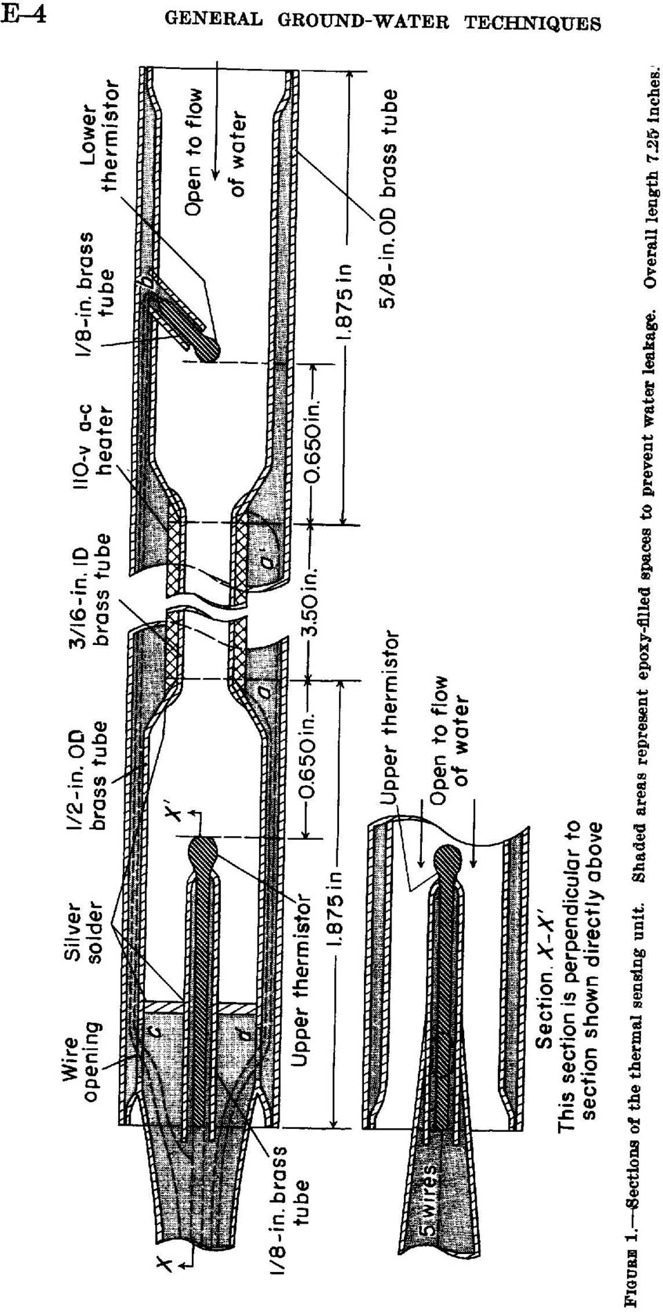
8 THERMAL FLOWMETER, MEASURING WELL-FLOW VELOCITY E-3 fpm could be useful too, the particular pilot model referred to in this report and most of the other experimental models used in this investigation were designed for measuring low velocities only. DESIGN OF FLOWMETER SENSING UNIT The sensing unit consists of a heating element, two thermistors, a brass body through which the water flows, and an outside housing (fig. 1). The body of the sensing unit is a %6-inch ID brass tube 3.50 inches long joined to two 1.8Y5-inch lengths of l/^-inch OD brass tubing. The total length of the sensing unit is Y.25 inches. The electric heating element is wound around the smaller brass tube. The outside of the heating element is coated with an insulating material to a diameter of half an inch. A thermistor is placed in each i/^-inch tube, inch from the ends of the narrower central tube which lines the heating element. The body of the sensing unit, including the thermistors and the heating element, is inserted into the outside housing, a %-inch OD brass tube. (See fig. 1.) The ends are soldered to seal the electrical components. To prevent water leakage where the thermistors protrude, a sealer composed of 100 parts by weight of Furane's No. 202 epoxy resin and 10 parts by weight of Furane's No. 951 Hardener fills the annular opening between the i/^-inch tube and the %-inch housing. A flattened tube houses the wires that leave the sensing unit; this tube also is filled with the same epoxy compound. The upper thermistor is a "Veco" No. 32A1D8, which is 2 inches long; the lower is a "Veco" No. 32A11-N8, which is l/2 incn l ng- These are nominal lengths and are trimmed to fit in their respective positions. In spite of their different lengths, their electrical characteristics are identical. The nominal resistance of each thermistor is 2,000 (±20 percent) ohms at 25 C. The two wires from the heating element, at points a and a! on figure 1, and the two leads from the bottom thermistor, at point Z>, are brought to the upper end of the sensing unit as shown in figure 1. The wires enter the body of the sensing unit through two holes near its top, at points c and d. The upper end of the body of the sensing tube is soldered to a %6-inch OD brass tube that has been flattened and forms a housing for all wires leaving the sensing unit. The flattened tube is soldered to the body in such a manner that it covers the wire openings but still allows the water to pass. This part of the unit is shown as'section X-X' at the bottom of figure 1. The maximum capacity of the heating element in the sensing unit is 100 watts in air. By setting the dial of a variable transformer, or

9 E-4 GENERAL GROUND-WATER TECHNIQUES
10 THERMAL FLOWMETER, MEASURING WELL-FLOW VELOCITY E-5 Variac (General Radio Corp., Type 200B), on the instrument panel, the output of the heating element can be positively and accurately controlled from 0 to 100 watts. The output amperage is read on an a-c ammeter in series with the output of the Variac to the heating element. The heating element described in this report uses 0.15 ampere. The two thermistors form two legs of a bridge circuit. One wire is common to both thermistors, and only 3 wires are needed for the circuitry of the 2 thermistors. In addition to the 3 wires for the 2 thermistors, 2 wires are required for the heating element. In the laboratory a 5-conductor cable, Belden 8455, was used, which provided 2 No. 18 and 3 No. 22 stranded wires. The 2 No. 18 wires are connected to the heating element and the 3 No. 22 wires are used for the thermistors. Belden 8455 cable comes in standard 250-foot lengths; longer lengths are available on special order from the manufacturer. A manufacturer has been contacted to produce a 5-prong quick connector for attaching the thermal sensing unit to the 5-wire cable. A connector could be made that would be watertight and sufficiently small (%-inch diameter) to allow the sensing unit to pass through small openings. Figure 2 shows a generalized diagrammatic view of the electrical circuit of the thermal sensing unit and its relation to the bridge circuit; figure 3 shows a detailed wiring diagram for the entire flowmeter and bridge unit. In the absence of heat from the heating element and with water passing through the unit, both thermistors are at the same temperature and the bridge can be balanced with 100-ohm bridge balance potentiometer. When heat is applied the signal thermistor is heated, and its resistance decreases so that more current will flow through this leg of the bridge. It is this current change, caused by the unbalancing of the bridge circuit, that is the signal to the differential amplifier and that is measured. The current changes are related in the laboratory to controlled velocities of water flowing through the meter, and a rating curve similar to that shown in figure 4 is developed. The rating curve shows the relation of changes in electrical current to changes in water velocity. Velocities in wells are then determined by using the rating curve. CONTROL UNIT The electronic controls (Variac and amplifier) of the thermal flowmeter are mounted on an 8- by 9%-inch panel. The makeup of the electronic control circuit is shown in detail in figure 3, and figure 5 shows the front of the instrument panel with the controls and their location. The panel is set in an S1/^- by 8- by 20-inch toolbox. The

11 E-6 GENERAL GROUND-WATER TECHNIQUES Bridge balance Signal out ll' ~ N5 v. 'WOW Vanac n =-6v 100 w AA/WW Heater Signal thermistor FIGURE 2. Generalized wiring diagram of thermal flowmeter. Temperaturecompensating thermistor

12 EXPLANATION h = henries t = thermistor K= 1000 ohms w = watts All resistors are half a watt unless marked otherwise All capacitors are in microfarads unless marked otherwise Circled numbers refer to items On instrument panel (see fig.5) FIGURE 3..Detailed wiring diagram of thermal flowmeter. (U.S. Pat )
 FIGURE 3..Detailed wiring diagram of thermal flowmeter. (U.S. Pat.")
13 E-8 GENERAL GROUND-WATER TECHNIQUES

14 Green - common/o O (o o) Black \o QO Balance O Log ^ 12 l3 I /" er or Brown lower thermistor 0... Red heater An enlarged view of item 19 CD 17 H \=0 I 468 O O O 9 ' l6 1. Line cord 2. Varlac 3. a-c ammeter 4. Varlac pilot light 5. Heat switch 6. Fuse 7. Fuse 8. Instrument pilot light 9. Power supply switch 10. Vent 11. Vent volt-battery Input 13. Bridge-balance and log switch 14. Mlcroammeter 15. Amplifier adjustment 16. One branch of bridge (screwdriver adjustment) FIGUBB 5. Sketch showing components of Instrument panel for thermal fiowmeter. 17. One branch of bridge (screwdriver adjustment) 18. Bridge-balance adjustment 19. Plug Input from sensing unit
 FIGUBB 5. Sketch showing components of Instrument panel for thermal fiowmeter. 17.")
15 E-10 GENERAL GROUND-WATER TECHNIQUES box is the type having a removable tray in the top. The tray is removed and the electronic panel is mounted on the brackets formerly used to hold the tray. The Variac (variable autotransformer) controls the heat output of the heating element. The resulting amperage is read on the a-c ammeter. The difference between the electrical currents flowing through the two thermistors is amplified so that it may be read more accurately on the microammeter. The amplifier is the differential type, with unit voltage gain. Its main purpose is for power gain; but, if desired, it could also drive a recorder. OPERATION OF INSTRUMENT The following procedure and instructions are recommended for logging with the pilot model of the experimental sensing unit. Numbers in parentheses refer to numbers on figure 5. Before logging is begun, connect the commutator line from the reel to the instrument receptacle (19) and plug in the line cord (1) to a 110-volt cycle line. Then lower the thermal sensing unit into the water in the well to be logged. Before turning on power or heat switch, follow procedures 1 and %. 1. Plug 6-volt battery lead into receptacle (12) and move bridgebalance and log switch (13) to the left to the word "balance." 2. Adjust microammeter (14) to zero, with bridge-balance potentiometer (18). Screwdriver-adjustment potentiometers (16) and (17) should be turned as far clockwise as possible unless unable to adjust with bridge-balance potentiometer (18). 3. Turn power-supply switch (9) on and allow 20 minutes for warmup. 4. Move bridge-balance and log switch (13) to the right to the word "log." Adjust microammeter (14) to 100 with the amplifier-adjustment potentiometer (15). 5. With Variac (2) turned to extreme counterclockwise position, turn on heat switch (5). 6. Adjust to desired heat with Variac (2). The a-c ammeter (3) registers the amount of current, which may be converted in terms of heat. 7. The velocity is determined on the rating curve by finding the value of velocity that corresponds to the microammeter (14) reading. Figure 4 is the rating curve for the pilot model of the thermal sensing unit. 8. Check instrument balance at intervals by turning heat switch off and allowing time for thermal sensing unit to cool. Microammeter (14) should return to a reading of 100. If not, readjust

16 THERMAL FLOWMETER, MEASURING WELL-FLOW VELOCITY E-ll instrument as in procedures 1, 2, and 4. Leave power-supply switch (9) on during this procedure to avoid warmup delay. Turn heat switch (5) on and read. 9. Turn heat switch (5) off when thermal sensing unit is out of the water, or the unit may be damaged. 10. Be sure to remove 6-volt battery plug when logging is finished. RESULTS A laboratory-constructed well, in which the vertical velocity could be controlled from 1 to 130 fpm, was used for testing several thermal sensing units. Each sensing unit required individual calibration. Although individual units may appear to be identical in construction, the velocity curves differ, probably because of differences in the electrical components or in the construction of the unit. The individual calibration applies only for the laboratory conditions and setup used. Adaptation to field use requires some modifications, such as centering devices and flow-channeling devices, to cope with the conditions peculiar to the site. An excellent discussion of some of the problems involved in the field use of a thermal flowmeter, and the techniques employed to overcome them, is given in a paper by Patten and Bennett (1962). Figure 4 shows the rating curve for one particular sensing unit having a % 6-inch ID bore through the heating element. Only one heat range, 0.15 ampere a. c., was used for this sensing unit. The higher temperatures produced by 0.2 or 0.25 ampere a. c. caused the sensing unit to become unstable at low velocities, and reliable readings were difficult to obtain for velocities less than 14 fpm. Sensing units having bore diameters greater than % 6 inch through the heating element were tested in various heat ranges, and separate rating curves were made for each. Measurement of high velocities required more heat from the heater, and baffles for mixing the heated water in the bore of the heating element to provide uniformly heated water. The readings, or velocity determinations, in the velocity ranges higher than 20 fpm have not been completely reliable, but enough work has been done to indicate that satisfactory results could be obtained by redesigning the heating element for more thorough mixing of heated water. The ability of the sensing unit described in this report to compensate for the temperature changes at different depths in the well bore was determined by dropping the temperature of the water l7 F at a known rate. The instrument responded with identical watervelocity readings time after time.

17 E-12 GENERAL GROUND-WATER TECHNIQUES Direction of flow, whether up or down a well bore, also could be detected with a properly designed sensing unit. Detection of downward flow was tried with the sensing unit described in this paper, but the detectable velocity range was found to be restricted to 7.5 to 20 fpm. The problem of measuring flow direction should be considered in any future experimentation and development. The vertical flowmeter described here is potentially an important aid to geologists and hydrologists first, because it is capable of logging extremely low velocities, which heretofore have not been detectable; and second, because of its small diameter, which permits it to be used in wells containing pump columns. The pilot instrument described is reliable in the low-velocity region; it is believed that this reliability could be extended to higher velocities by further experimentation in design. Eventually it may be possible to incorporate all the features needed for low and high velocities into a single sensing unit. REFERENCE Patten, E. P. and Bennett, G.D. (1962), Methods of flow measurement in well bores : U.S. Geol. Survey Water-Supply Paper 1544-C, 28 p. U.S. GOVERNMENT PRINTING OFFICE : 1962 O

PHYSICS 111 LABORATORY Experiment #3 Current, Voltage and Resistance in Series and Parallel Circuits
 PHYSCS 111 LABORATORY Experiment #3 Current, Voltage and Resistance in Series and Parallel Circuits This experiment is designed to investigate the relationship between current and potential in simple series
6/14/02 Chapter 14: Use of Electrical Test Equipment 1/20
 USE OF ELECTRICAL TEST EQUIPMENT Test equipment is necessary for determining proper set-up, adjustment, operation, and maintenance of electrical systems and control panels. The following is a general procedure
Voltage Drop (Single-Phase)
") Voltage Drop (Single-Phase) To Find: To Find Voltage Drop Formula: 2 x K x L x I V.D. = ------------------- C.M. Variables: C.M. = Circular Mill Area (Chapter 9, Table 8) To Find Voltage Drop Percentage
Voltage Drop (Single-Phase) To Find: To Find Voltage Drop Formula: 2 x K x L x I V.D. = ------------------- C.M. Variables: C.M. = Circular Mill Area (Chapter 9, Table 8) To Find Voltage Drop Percentage
Physics 3330 Experiment #2 Fall 1999. DC techniques, dividers, and bridges R 2 =(1-S)R P R 1 =SR P. R P =10kΩ 10-turn pot.
R P R 1 =SR P. R P =10kΩ 10-turn pot.") Physics 3330 Experiment #2 Fall 1999 DC techniques, dividers, and bridges Purpose You will gain a familiarity with the circuit board and work with a variety of DC techniques, including voltage dividers,
Physics 3330 Experiment #2 Fall 1999 DC techniques, dividers, and bridges Purpose You will gain a familiarity with the circuit board and work with a variety of DC techniques, including voltage dividers,
FREQUENCY RESPONSE OF AN AUDIO AMPLIFIER
 2014 Amplifier - 1 FREQUENCY RESPONSE OF AN AUDIO AMPLIFIER The objectives of this experiment are: To understand the concept of HI-FI audio equipment To generate a frequency response curve for an audio
Ohm's Law and Circuits
 2. Conductance, Insulators and Resistance A. A conductor in electricity is a material that allows electrons to flow through it easily. Metals, in general, are good conductors. Why? The property of conductance
Assembly Instructions: Shortwave Radio Kit
 Assembly Instructions: Shortwave Radio Kit MTM Scientific, Inc P.O. Box 522 Clinton, MI 49236 U.S.A Introduction Fig 1: The assembled Shortwave Radio Kit The SHORTWAVE RADIO KIT (#SWRAD) from MTM Scientific
7. What is the current in a circuit if 15 coulombs of electric charge move past a given point in 3 seconds? (1) 5 A (3) 18 A (2) 12 A (4) 45 A
 5 A (3) 18 A (2) 12 A (4) 45 A") 1. Compared to the number of free electrons in a conductor, the number of free electrons in an insulator of the same volume is less the same greater 2. Most metals are good electrical conductors because
1. Compared to the number of free electrons in a conductor, the number of free electrons in an insulator of the same volume is less the same greater 2. Most metals are good electrical conductors because
Lab E1: Introduction to Circuits
 E1.1 Lab E1: Introduction to Circuits The purpose of the this lab is to introduce you to some basic instrumentation used in electrical circuits. You will learn to use a DC power supply, a digital multimeter
Experiment #4, Ohmic Heat
 Experiment #4, Ohmic Heat 1 Purpose Physics 18 - Fall 013 - Experiment #4 1 1. To demonstrate the conversion of the electric energy into heat.. To demonstrate that the rate of heat generation in an electrical
tidesmarine Smart Seal Temperature Alarm System Generation II Installation Instructions Starboard side cable
 tidesmarine Smart Seal Temperature Alarm System Generation II Installation Instructions Starboard side cable Port side cable (with black cable tie attached) Power cable Preparing for Installation 1 Overall
3. SEISCO PARTS & SERVICE REMOVAL AND REPAIR GUIDE
 4 3. SEISCO PARTS & SERVICE REMOVAL AND REPAIR GUIDE A. Changing the Control Board B. Replacing a Heating Element C. Thermistor Replacement D. High Limit Switch Replacement E. Level Detector Replacement
1. The diagram below represents magnetic lines of force within a region of space.
 1. The diagram below represents magnetic lines of force within a region of space. 4. In which diagram below is the magnetic flux density at point P greatest? (1) (3) (2) (4) The magnetic field is strongest
(Issued 1 Dec. 1965) CRD-C 45-65 METHOD OF TEST FOR THERMAL CONDUCTIVITY OF LIGHTWEIGHT INSULATING CONCRETE 1
 CRD-C 45-65 METHOD OF TEST FOR THERMAL CONDUCTIVITY OF LIGHTWEIGHT INSULATING CONCRETE 1") CRD-C 45-65 METHOD OF TEST FOR THERMAL CONDUCTIVITY OF LIGHTWEIGHT INSULATING CONCRETE 1 Scope 1. This method of test covers a procedure for measuring the thermal conductivity of lightweight concrete of
CRD-C 45-65 METHOD OF TEST FOR THERMAL CONDUCTIVITY OF LIGHTWEIGHT INSULATING CONCRETE 1 Scope 1. This method of test covers a procedure for measuring the thermal conductivity of lightweight concrete of
Lab 3 - DC Circuits and Ohm s Law
 Lab 3 DC Circuits and Ohm s Law L3-1 Name Date Partners Lab 3 - DC Circuits and Ohm s Law OBJECTIES To learn to apply the concept of potential difference (voltage) to explain the action of a battery in
Resistance, Ohm s Law, and the Temperature of a Light Bulb Filament
 Resistance, Ohm s Law, and the Temperature of a Light Bulb Filament Name Partner Date Introduction Carbon resistors are the kind typically used in wiring circuits. They are made from a small cylinder of
Active Speaker System LX523 AUDAC PROFESSIONAL AUDIO EQUIPMENT. Active Speaker System with remote input LX523. User Manual & Installation Guide
 Active Speaker System LX523 AUDAC PROFESSIONAL AUDIO EQUIPMENT Active Speaker System with remote input LX523 User Manual & Installation Guide AUDAC PROFESSIONAL AUDIO EQUIPMENT User Manual & Installation
PS4-24 OWNERS MANUAL 24 VAC 90 WATT WALL MOUNTED CCTV POWER SUPPLY
 PS4-24 OWNERS MANUAL 24 VAC 90 WATT WALL MOUNTED CCTV POWER SUPPLY 7320 Ashcroft, Suite 104 Houston, Texas 77081 p: 713-772-1404 f: 713-772-7360 e: info@juicegoose.com www.juicegoose.com 06-06 CONGRATULATIONS
Objectives 200 CHAPTER 4 RESISTANCE
 Objectives Explain the differences among conductors, insulators, and semiconductors. Define electrical resistance. Solve problems using resistance, voltage, and current. Describe a material that obeys
22.302 Experiment 5. Strain Gage Measurements
 22.302 Experiment 5 Strain Gage Measurements Introduction The design of components for many engineering systems is based on the application of theoretical models. The accuracy of these models can be verified
Streaming Potential System (SPT1000, SPD1000)
") Streaming Potential System (SPT1000, SPD1000) User's Manual Sentrol Systems, Inc. 3949 Cotswold Dr. SW, Lilburn, GA 30047-2371 Tel: 770-564-1541, Fax: 770-564-8605 www.sentrolsystems.com Since the streaming
Streaming Potential System (SPT1000, SPD1000) User's Manual Sentrol Systems, Inc. 3949 Cotswold Dr. SW, Lilburn, GA 30047-2371 Tel: 770-564-1541, Fax: 770-564-8605 www.sentrolsystems.com Since the streaming
OEM Manual MODEL 2350 ELECTRONIC DUAL CYLINDER SCALE
 OEM Manual MODEL 2350 ELECTRONIC DUAL CYLINDER SCALE Scaletron Industries, Ltd. Bedminster Industrial Park 53 Apple Tree Lane P.O. Box 365 Plumsteadville, PA 18949 USA Toll Free: 1-800-257-5911 (USA &
EXPERIMENT 7 OHM S LAW, RESISTORS IN SERIES AND PARALLEL
 260 7- I. THEOY EXPEIMENT 7 OHM S LAW, ESISTOS IN SEIES AND PAALLEL The purposes of this experiment are to test Ohm's Law, to study resistors in series and parallel, and to learn the correct use of ammeters
MODEL 5010 DUAL CHANNEL SMOKE/FIRE DETECTION MODULE
 DESCRIPTION MODEL 5010 DUAL CHANNEL SMOKE/FIRE DETECTION MODULE DESCRIPTION The SST Model 5010 Two Channel Smoke/Fire Detection Module provides two independent detection input channels for the NOVA-5000
VOYAGER 570G. 744A Sprayer Control
 VOYAGER 570G 744A Sprayer Control U S E R M A N U A L U S E R M A N U A L Table of Contents CHAPTER 1 - INTRODUCTION...1 SYSTEM CONFIGURATIONS...1 KIT CONTENTS...3 CONTROL HOUSING ASSEMBLY...5 CHAPTER
INSTALLATION GUIDE. Card Reader & Controller with KIM Swipe Reader for Solitaire 850 / 950 / 850L Learnlok PK2930
 INSTALLATION GUIDE Card Reader & Controller with KIM Swipe Reader for Solitaire 850 / 950 / 850L Learnlok PK2930 Card Reader and Controller Model 3.5 with KIM Swipe Reader Table of Contents 1. Features..................................
Kit 106. 50 Watt Audio Amplifier
 Kit 106 50 Watt Audio Amplifier T his kit is based on an amazing IC amplifier module from ST Electronics, the TDA7294 It is intended for use as a high quality audio class AB amplifier in hi-fi applications
SDI Multi Sensor Module with Charger Enclosure Station Support
 Description The purpose of the is to provide a low power temperature compensated battery charge controller and a general-purpose interface for analog sensors. Sensor and charge controller data are acquired
THE MclNTOSH MC 2100 SOLID STATE STEREO POWER AMPLIFIER
 THE MclNTOSH MC 2100 SOLID STATE STEREO POWER AMPLIFIER Price $1.25 Your MC 2100 stereo amplifier will give you many years of pleasant and satisfactory performance. If you have any questions concerning
RI-215A Operator s Manual. Part Number: 71-0045RK Revision 0 Released: 10/3/05
 RI-215A Operator s Manual Part Number: 71-0045RK Revision 0 Released: 10/3/05 Warranty RKI Instruments, Inc., warrants gas alarm equipment sold by us to be free from defects in materials and workmanship,
Experiment NO.3 Series and parallel connection
 Experiment NO.3 Series and parallel connection Object To study the properties of series and parallel connection. Apparatus 1. DC circuit training system 2. Set of wires. 3. DC Power supply 4. Digital A.V.O.
CONNECTOR AMPLIFIER FOR PROPORTIONAL VALVES (4-20 ma Input Version)
") TECHNICAL DATASHEET #TD1102AX CONNECTOR AMPLIFIER FOR PROPORTIONAL VALVES (4-20 ma Input Version) Part Number: Connector Amplifier CAPV-H-4-20MA-x complete with cable CAPV-4C-yM Where: x = current output
TECHNICAL DATASHEET #TD1102AX CONNECTOR AMPLIFIER FOR PROPORTIONAL VALVES (4-20 ma Input Version) Part Number: Connector Amplifier CAPV-H-4-20MA-x complete with cable CAPV-4C-yM Where: x = current output
MODEL 2202IQ (1991-MSRP $549.00)
") F O R T H E L O V E O F M U S I C F O R T H E L O V E O F M U S I C MODEL 2202IQ (1991-MSRP $549.00) OWNER'S MANUAL AND INSTALLATION GUIDE INTRODUCTION Congratulations on your decision to purchase a LINEAR
F O R T H E L O V E O F M U S I C F O R T H E L O V E O F M U S I C MODEL 2202IQ (1991-MSRP $549.00) OWNER'S MANUAL AND INSTALLATION GUIDE INTRODUCTION Congratulations on your decision to purchase a LINEAR
Installation Instructions
 H5HK Series Installation Instructions 3 Phase Electric Heater Kits 7.5 and 0 TON Package A/C Systems Description Installation of 08/40V and 480V H5HK 3 Phase Heater Kits in 7.5 and 0 TON Packaged Air Conditioners.
PORTER MASS FLOW MEASUREMENT AND CONTROL SYSTEMS
 PORTER MASS MEASUREMENT AND CONTROL SYSTEMS PORTER: THE STANDARD OF EXCELLENCE IN MASS Porter Mass Flow products reflect nearly three decades of experience in the design and manufacture of precision instruments
V94 BULK TAPE DEGAUSSER
 TECHNICAL MANUAL Operating and Maintenance Instructions for V94 BULK TAPE DEGAUSSER V94 BULK TAPE DEGAUSSER TECHNICAL MANUAL Document No. M000208 Production Standard ZZ 009 415 WARNING To help minimise
LOXONE 12 Channel Amplifier
 LOXONE 12 Channel Amplifier Item no.: 200110 Thank you for purchasing the Loxone Twelve Channel Amplifier. The versatility of the Amplifier makes it the perfect choice for almost every type of custom multi-room
DET Practical Electronics (Intermediate 1)
") DET Practical Electronics (Intermediate 1) 731 August 2000 HIGHER STILL DET Practical Electronics (Intermediate 1) Support Materials CONTENTS Section 1 Learning about Resistors Section 2 Learning about
DET Practical Electronics (Intermediate 1) 731 August 2000 HIGHER STILL DET Practical Electronics (Intermediate 1) Support Materials CONTENTS Section 1 Learning about Resistors Section 2 Learning about
TECHNICAL DATASHEET #TD1404AX PWM CONTROLLED SOLENOID DRIVER
 TECHNICAL DATASHEET #TD1404AX PWM CONTROLLED SOLENOID DRIVER (PWM Input, 1.2A or 2A Output, Metal Box or PCB) PCB Board - P/N: PWMC-PCB-2A, PWMC-PCB-1.2A Packaged Driver (metal box with 1.5 m (5 ft.) cable)
People s Physics Book
 The Big Ideas: The name electric current is given to the phenomenon that occurs when an electric field moves down a wire at close to the speed of light. Voltage is the electrical energy density (energy
Installation and Troubleshooting Instructions for Electric Tankless Residential Water Heaters.
 Model Number: Serial Number: Information Manual Installation and Troubleshooting Instructions for Electric Tankless Residential Water Heaters. ATTENTION: IF YOU ARE NOT A LICENSED PLUMBER OR A LICENSED
Name of Equipment Silver King Model SKMCD1P/C1. This equipment chapter is to be inserted in the appropriate section of the Equipment Manual.
 Name of Equipment Silver King Model SKMCD1P/C1 This equipment chapter is to be inserted in the appropriate section of the Equipment Manual. Manufactured exclusively for McDonald s By Silver King Refrigeration,
Using Thermocouple Sensors Connecting Grounded and Floating Thermocouples
 Connecting Grounded and Floating Thermocouples For best performance, Thermocouple sensors should be floating. This will ensure that no noise currents can flow in the sensor leads and that no common-mode
Using and Wiring Light Emitting Diodes (LEDs) for Model Railroads
 for Model Railroads") Using and Wiring Light Emitting Diodes (LEDs) for Model Railroads LEDs have many useful applications in Model railroading, including: Locomotive headlights Rear-end warning lights for cabooses and passenger
Using and Wiring Light Emitting Diodes (LEDs) for Model Railroads LEDs have many useful applications in Model railroading, including: Locomotive headlights Rear-end warning lights for cabooses and passenger
CALIBRATION OF A THERMISTOR THERMOMETER (version = fall 2001)
") CALIBRATION OF A THERMISTOR THERMOMETER (version = fall 2001) I. Introduction Calibration experiments or procedures are fairly common in laboratory work which involves any type of instrumentation. Calibration
CALIBRATION OF A THERMISTOR THERMOMETER (version = fall 2001) I. Introduction Calibration experiments or procedures are fairly common in laboratory work which involves any type of instrumentation. Calibration
TECHNICAL SERVICE DEPARTMENT Technical Service Bulletin 1-800-432-8373. Tankless Electric (RTE) Troubleshooting
 Troubleshooting") Sequence of Operations 1 Power supply and field wiring block 2 Energy Cut Off (ECO) 3 Water flow plunger and cold inlet 4 Magnetic flow switch 5 Water temperature thermistor 6 Control panel and circuit
Sequence of Operations 1 Power supply and field wiring block 2 Energy Cut Off (ECO) 3 Water flow plunger and cold inlet 4 Magnetic flow switch 5 Water temperature thermistor 6 Control panel and circuit
What is a multimeter?
 What is a multimeter? A multimeter is a devise used to measure voltage, resistance and current in electronics & electrical equipment It is also used to test continuity between to 2 points to verify if
bba - Balboa Bluetooth Audio (AMP) Installation & User Guide
 Installation & User Guide") bba - Balboa Bluetooth Audio (AMP) Installation & User Guide Bluetooth Integration CONNECT YOUR SMART DEVICE TO YOUR HOT TUB With Bluetooth connection you can now play all your favorite songs directly
bba - Balboa Bluetooth Audio (AMP) Installation & User Guide Bluetooth Integration CONNECT YOUR SMART DEVICE TO YOUR HOT TUB With Bluetooth connection you can now play all your favorite songs directly
Roof Top Air Conditioner INSTALLATION AND OPERATING INSTRUCTIONS
 Roof Top Air Conditioner INSTALLATION AND OPERATING INSTRUCTIONS Ducted System RECORD THIS UNIT INFORMATION FOR FUTURE REFERENCE: Model Number: Serial Number: Date Purchased: This manual must be read and
Fundamentals of Power
 Fundamentals of Power Fundamentals of Power 2008 American Power Conversion Corporation. All rights reserved. All trademarks provided are the property of their respective owners. Learning Objectives At
ETC TWO STAGE ELECTRONIC TEMPERATURE CONTROL
 RANCO INSTALLATION INSTRUCTIONS ETC TWO STAGE ELECTRONIC TEMPERATURE CONTROL Relay Electrical Ratings PRODUCT DESCRIPTION The Ranco ETC is a microprocessor-based family of electronic temperature controls,
Advantium 2 Plus Alarm
 ADI 9510-B Advantium 2 Plus Alarm INSTALLATION AND OPERATING INSTRUCTIONS Carefully Read These Instructions Before Operating Carefully Read These Controls Corporation of America 1501 Harpers Road Virginia
Service Guide 12/27/03 TESTING, SERVICE & REPAIR GUIDE (For SH Space Heating Models & RA Water Heating Models)
") TESTING, SERVICE & REPAIR GUIDE (For SH Space Heating Models & RA Water Heating Models) WARNING - HIGH VOLTAGE AC electrical circuits are connected to this heater. Do not attempt any service work on the
TESTING, SERVICE & REPAIR GUIDE (For SH Space Heating Models & RA Water Heating Models) WARNING - HIGH VOLTAGE AC electrical circuits are connected to this heater. Do not attempt any service work on the
Troubleshooting Guide, Freedom and Fleet Power Inverter/Chargers
 Technical Note Freedom/Fleet Power 512-0084-01-01 Rev 1 Troubleshooting Guide, Freedom and Fleet Power Inverter/Chargers Overview This document is a guide for troubleshooting inverters, battery chargers,
Parallel Circuits. Objectives After studying this chapter, you will be able to answer these questions: 1. How are electrical components connected
 This sample chapter is for review purposes only. Copyright The Goodheart-Willcox Co., Inc. All rights reserved. Electricity Objectives After studying this chapter, you will be able to answer these questions:.
By Authority Of THE UNITED STATES OF AMERICA Legally Binding Document
 By Authority Of THE UNITED STATES OF AMERICA Legally Binding Document By the Authority Vested By Part 5 of the United States Code 552(a) and Part 1 of the Code of Regulations 51 the attached document has
WHOLESALE DIRECT INC. 5620 WEST 65TH STREET
 Auto Pump V 200 100 0 100 Max Rating Vehicle mount compressor ensures truck air brake system is properly pressurized for immediate dispatch from station Pressure switch regulated operation automatically
RESULTS OF ICARUS 9 EXPERIMENTS RUN AT IMRA EUROPE
 Roulette, T., J. Roulette, and S. Pons. Results of ICARUS 9 Experiments Run at IMRA Europe. in Sixth International Conference on Cold Fusion, Progress in New Hydrogen Energy. 1996. Lake Toya, Hokkaido,
E2 Series Electric Furnaces
 E2 Series Electric Furnaces Service Manual Table of Contents Electrical Requirements... 10 Codes, Specifications Requirements... 10 Connection Supply Service Wires... 10 Furnace Sequence of Operation...
DC LOAD TESTING Gian Trento June 18 th, 2004
 DC LOAD TESTING Gian Trento June 18 th, 2004 THIS TECHNICAL NOTE DESCRIBES THE PROCESS OF CONNECTING THE UNIVERSAL VOLTRONICS CORPORATION (UVC) POWER SYSTEM TO THE DC LOAD AS WELL AS OPERATING THE UVC
Owner s Manual AWM910 JENSEN AWM910 COMPACT DISC PLAYER RADIO CD COMPACT MUSIC SYSTEM MUTE AUX BAND AUX IN PUSH PUSH PWR VOL ALARM T/F AUD SPK A SPK B
 AWM910 Owner s Manual COMPACT DISC PLAYER PUSH 1 2 3 4 5 6 RPT SCAN RDM H M PUSH PWR VOL ALARM SET ON/OFF EQ T/F AUD RADIO CD COMPACT MUSIC SYSTEM MUTE AUX BAND CD AUX IN A B A+B JENSEN AWM910 Thank You!
ATL Fuel Level Sender Probes
 T E C H N I C A L S P E C I F I C A T I O N The ATL EL-AD-151 (Resistance Output) and EL-AD-152 (Voltage Output) Fuel Level Senders are highly advanced sensors for continuously measuring the contents of
Automatic Voltage Regulator User s Manual
 Resp. dept. R&D We reserve all rights in this document and in the information contained therein. Reproduction, use or disclosure to third parties without express authority is strictly forbidden. Copyright
Extender for HDMI Long Range. www.gefentv.com GTV-HDMI-CAT5LR. User Manual
 Extender for HDMI Long Range GTV-HDMI-CAT5LR User Manual www.gefentv.com Technical Support: Telephone (818) 772-9100 (800) 545-6900 Fax (818) 772-9120 Technical Support Hours: 8:00 AM to 5:00 PM Monday
OPL BASIC. Dosing System for Professional Laundry machines. Contents
 OPL BASIC Dosing System for Professional Laundry machines Contents 1 Getting Started. Page 2 2 Installation. Page 4 3 Set Up & Operation. Page 8 4 Maintenance & Accessories. Page 10 5 Troubleshooting Page
Current valve. for AC 24 V pulse/pause control of electrical loads up to 30 kw
 4 937 DESIO Current valve for AC 24 V pulse/pause control of electrical loads up to 30 kw SEA45.1 Use The current valve is used for the control of electric heating elements in heating, ventilation and
Calibration and Use of a Strain-Gage-Instrumented Beam: Density Determination and Weight-Flow-Rate Measurement
 Chapter 2 Calibration and Use of a Strain-Gage-Instrumented Beam: Density Determination and Weight-Flow-Rate Measurement 2.1 Introduction and Objectives This laboratory exercise involves the static calibration
Analog control unit for mobile robots
 Analog control unit for mobile robots Soldering kit for experimentation For Fischertechnik robots and others Most diverse functions Requires no programming Patented sensor technology Summary We are pleased
BUILDING INSTRUCTIONS
 etap2hw 38 mm I2C to LCD Interface BUILDING INSTRUCTIONS October 2013 P. Verbruggen Rev 1.01 15-Oct-13 Page 1 Table of Contents Chapter 1 General Information 1.1 ESD Precautions 1.2 Further Supplies 1.3
Troubleshooting accelerometer installations
 Troubleshooting accelerometer installations Accelerometer based monitoring systems can be tested to verify proper installation and operation. Testing ensures data integrity and can identify most problems.
************* OWNER'S MANUAL BAMF800/2 BAMF1250/2 BAMF1800/2 BAMF2200/2 BAMF2600/2 BAMF1200/4 BAMF1600/4 BAMF2000/1D BAMF4000/1D BAMF5500/1D
 ************* OWNER'S MANUAL BAMF800/2 BAMF1250/2 BAMF1800/2 BAMF2200/2 BAMF2600/2 BAMF1200/4 BAMF1600/4 BAMF2000/1D BAMF4000/1D BAMF5500/1D INTRODUCTION Power Acoustik amplifiers provide high-performance
Electronics. Discrete assembly of an operational amplifier as a transistor circuit. LD Physics Leaflets P4.2.1.1
 Electronics Operational Amplifier Internal design of an operational amplifier LD Physics Leaflets Discrete assembly of an operational amplifier as a transistor circuit P4.2.1.1 Objects of the experiment
SERVICE TIPS. Dometic REFRIGERATORS. Models. OS1927 4/96 Copyright 1996 The Dometic Corporation
 SERVICE TIPS Dometic REFRIGERATORS Models RM2612 RM2652 RM2812 RM2852 OS1927 4/96 Copyright 1996 The Dometic Corporation THE MOST COMMON SYSTEM PROBLEMS ASSOCIATED WITH THE RM2612, RM2812, RM2652, RM2852
SX460. Generator Automatic Voltage Regulator Operation Manual
 SX460 Generator Automatic Voltage Regulator Operation Manual Self Excited Automatic Voltage Regulator Compatible with Newage SX460* * Use for reference purpose only and not a genuine Newage product. 1.
INSTALLATION & SERVICE MANUAL. Display Panel
 INSTALLATION & SERVICE MANUAL Display Panel The PowerLine EMS TM is a specialized power distribution and energy management system intended to be used in recreational vehicles. The Control Module is housed
Bill Conkling July 2012
 Bill Conkling July 2012 Introduction: For any ham, there are moments that are priceless, like snagging that elusive rare DX station on a deserted island that hasn t been activated in 52 years. And certainly,
Technical Update TAA.TU.11093 Rev. 1
 http://www.gambro.com/en/usa_tech/ 800-525-2623 303-222-6500 Technical Update TAA.TU.11093 Rev. 1 Effective: 05 APR 2013 CO# 13084 Product: Subject: From: Phoenix Dialysis System Required Electrical Safety
How To Read A Pipe From A Sensor
 Liquid Level Sensor Installation on pipes. Sensing by means electrostatic capacity and is not influenced by the color of the pipe or liquid. Available in 8 to mm dia. and to mm dia. models to enable sensing
SYSTEM 4C. C R H Electronics Design
 SYSTEM 4C C R H Electronics Design SYSTEM 4C All in one modular 4 axis CNC drive board By C R Harding Specifications Main PCB & Input PCB Available with up to 4 Axis X, Y, Z, A outputs. Independent 25
User s Manual. BNC Mini-High Res, 75 Ohm Termination Kit Connector Installation Guide (60-073-01)
") User s Manual BNC Mini-High Res, 75 Ohm Termination Kit Connector Installation Guide (60-073-01) BNC Termination Kit Instructions This document is a compilation of Extron s instructions, together with
User s Manual BNC Mini-High Res, 75 Ohm Termination Kit Connector Installation Guide (60-073-01) BNC Termination Kit Instructions This document is a compilation of Extron s instructions, together with
Series and Parallel Circuits
 Series and Parallel Circuits Components in a circuit can be connected in series or parallel. A series arrangement of components is where they are inline with each other, i.e. connected end-to-end. A parallel
TEST PLAN SUPERSEDES: None
 NYE COUNTY NUCLEAR WASTE REPOSITORY PROJECT OFFICE TEST PLAN TITLE: Thermal Logging in Early Warning Drilling Program Wells Using Sensornet Equipment Revision: 0 Date: 6-19-06 Page: 1 of 10 TEST PLAN NUMBER:
01-3 0000-00 6810-20 AIR CONDITIONING SYSTEM 1. FFH SPECIFICATION AIR CONDITIONING SYSTEM RODIUS 2004.09
 0000-00 01-3 6810-20 1. FFH SPECIFICATION 01-4 0000-00 2. SYSTEM LAYOUT AND COMPONENTS 0000-00 01-5 01-6 0000-00 3. FFH GENERAL INFORMATION The system is to increase the coolant temperature quickly by
Chapter 7 Direct-Current Circuits
 Chapter 7 Direct-Current Circuits 7. Introduction...7-7. Electromotive Force...7-3 7.3 Resistors in Series and in Parallel...7-5 7.4 Kirchhoff s Circuit Rules...7-7 7.5 Voltage-Current Measurements...7-9
SECTION 4 ELECTRIC MOTORS UNIT 17: TYPES OF ELECTRIC MOTORS
 SECTION 4 ELECTRIC MOTORS UNIT 17: TYPES OF ELECTRIC MOTORS UNIT OBJECTIVES After studying this unit, the reader should be able to Describe the different types of open single-phase motors used to drive
Sanitary Type Electronic Flow Switches
 Industries Pharmaceutical Sanitary Type Electronic Flow Switches Food and Beverage Biotechnology Semiconductor Water Treatment S Series Ameritrol, Inc. Instruments and Controls Features No Moving Parts
Errors Related to Cable Resistance Imbalance in Three Wire RTDs
 Errors Related to Cable Resistance Imbalance in Three Wire RTDs 1.0 Introduction There are multiple sources of error that can impact the accuracy of an RTD measurement. The cable incorporated into the
Quanser NI-ELVIS Trainer (QNET) Series: QNET HVAC. Heating, Ventilation, and Air Conditioning (HVAC) User Manual. User Manual
 Series: QNET HVAC. Heating, Ventilation, and Air Conditioning (HVAC) User Manual. User Manual") Quanser NI-ELVIS Trainer (QNET) Series: QNET HVAC Heating, Ventilation, and Air Conditioning (HVAC) User Manual User Manual Table of Contents 1. Introduction...1 2. Requirements...1 3. References...1 4.
Quanser NI-ELVIS Trainer (QNET) Series: QNET HVAC Heating, Ventilation, and Air Conditioning (HVAC) User Manual User Manual Table of Contents 1. Introduction...1 2. Requirements...1 3. References...1 4.
Electrical Resonance
 Electrical Resonance (R-L-C series circuit) APPARATUS 1. R-L-C Circuit board 2. Signal generator 3. Oscilloscope Tektronix TDS1002 with two sets of leads (see Introduction to the Oscilloscope ) INTRODUCTION
Parallel Plate Capacitor
 Parallel Plate Capacitor Capacitor Charge, Plate Separation, and Voltage A capacitor is used to store electric charge. The more voltage (electrical pressure) you apply to the capacitor, the more charge
Water Leak Detection System
 Water Leak Detection System Installation and Operating Manual 505-334-5865 ph 505-334-5867 fax www.rodisystems.com email:info@rodisystems.com 936 Highway 516 Aztec, NM 87410-2828 Manual Revisions and Copyright
SECTION 15750 PACKAGED ROOFTOP AIR CONDITIONING UNITS
 SECTION 15750 PART 1 - GENERAL 1.01 DESCRIPTION A. Section includes requirements for roof mounted, self-contained units, with electric cooling, and electric or reverse refrigeration cycle (heat pump) heating
ABB ! CAUTION. Type COQ Negative Sequence Generator Relay. (50/60 Hertz) 41-161J. Instruction Leaflet
 41-161J. Instruction Leaflet") ABB Instruction Leaflet 41-161J Effective: May 1997 Supersedes I.L. 41-161H Dated July 1984 ( ) Denotes Change Since Previous Issue Type COQ Negative Sequence Generator Relay (50/60 Hertz)! CAUTION Before
ABB Instruction Leaflet 41-161J Effective: May 1997 Supersedes I.L. 41-161H Dated July 1984 ( ) Denotes Change Since Previous Issue Type COQ Negative Sequence Generator Relay (50/60 Hertz)! CAUTION Before
Modifying the Yaesu FT-847 External 22.625 MHz Reference Input
 Modifying the Yaesu FT-847 External 22.625 MHz Reference Input David Smith VK3HZ Introduction This document describes the modification of an FT-847 to allow an external 22.625 MHz Reference oscillator
Build A Video Switcher. Reprinted with permission from Electronics Now Magazine September 1997 issue
 Build A Video Switcher Reprinted with permission from Electronics Now Magazine September 1997 issue Copyright Gernsback Publications, Inc.,1997 BUILD A VIDEO SWITCHER FRANK MONTEGARI Watch several cameras
INSTALLATION INSTRUCTIONS
 INSTALLATION INSTRUCTIONS Application Outboards Faria 5 Gauge Set* Publication No. Description Part Number Honda Code PII53606A White faced, flat lens 06300-ZW5-010ZB 6315410 Issue Date Black faced, flat
Building the AMP Amplifier
 Building the AMP Amplifier Introduction For about 80 years it has been possible to amplify voltage differences and to increase the associated power, first with vacuum tubes using electrons from a hot filament;
CURRENT TRANSFORMER MODEL 546 UL1015 #16 AWG LEAD WIRE, STANDARD LENGTH IS 24" 1 X
 CURRENT TRANSFORMER MODEL 546 1.10" I.D. PAGE No 1-38 REV 15DEC00 TERMINAL OPTION LEAD WIRE OPTION 1.10 0 1.20 2.55 3.00 3.47 0.18 x 0.31 SLOT ( 2 PLACES) 8-32 BRASS STUD (2 PLACES) UL1015 #16 AWG LEAD
1978-83 Malibu 1978-87 Monte Carlo 1978-87 El Camino
 Important facts about this kit. 1. The dash panel used in this picture is used by permission of Covan's Classic. 2. This kit requires some modification to your original under dash wiring harness. It is