Compound Miter Saw Model C 10FCH2 C 10FCE2. Handling instructions
|
|
|
- Karin Richards
- 10 years ago
- Views:
Transcription
1 Compound Miter Saw Model C 10FCH2 C 10FCE2 Handling instructions Note: Before using this Electric Power Tool, carefully read through these HANDLING INSTRUCTIONS to ensure efficient, safe operation. It is recommended that these INSTRUCTIONS be kept readily available as an important reference when using this power tool.

2 GENERAL OPERATIONAL PRES WARNING! When using electric tools, basic safety precautions should always be followed to reduce the risk of fire, electric shock and personal injury, including the following. Read all these instructions before operating this product and save these instructions. For safe operations: 1. Keep work area clean. Cluttered areas and benches invite injuries. 2. Consider work area environment. Do not expose power tools to rain. Do not use power tools in damp or wet locations. Keep work area well lit. Do not use power tools where there is risk to cause fire or explosion. 3. Guard against electric shock. Avoid body contact with earthed or grounded surfaces (e.g. pipes, radiators, ranges, refrigerators). 4. Keep children and infirm persons away. Do not let visitors touch the tool or extension cord. All visitors should be kept away from work area. 5. Store idle tools. When not in use, tools should be stored in a dry, high or locked up place, out of reach of children and infirm persons. 6. Do not force the tool. It will do the job better and safer at the rate for which it was intended. 7. Use the right tool. Do not force small tools or attachments to do the job of a heavy duty tool. Do not use tools for purposes not intended; for example, do not use circular saw to cut tree limbs or logs. 8. Dress properly. Do not wear loose clothing or jewelry, they can be caught in moving parts. Rubber gloves and non-skid footwear are recommended when working outdoors. Wear protecting hair covering to contain long hair. 9. Use eye protection. Also use face or dust mask if the cutting operation is dusty. 10. Connect dust extraction equipment. Cutting operation by this compound miter saw may produce considerable amount of dust from extraction duct on fixed guard. (Dust material: Wood or Aluminium) If devices are provided for the connection of dust extraction and collection facilities ensure these are connected and properly used. 11. Do not abuse the cord. Never carry the tool by the cord or yank it to disconnect it from the receptacle. Keep the cord away from heat, oil and sharp edges. 12. Secure work. Use clamps or a vise to hold the work. It is safer than using your hand and it frees both hands to operate tool. 13. Do not overreach. Keep proper footing and balance at all times. 14. Maintain tools with care. Keep cutting tools sharp and clean for better and safer performance. Follow instructions for lubrication and changing accessories. Inspect tool cords periodically and if damaged, have it repaired by authorized service center. Inspect extension cords periodically and replace, if damaged. Keep handles dry, clean, and free from oil and grease. 15. Disconnect tools. When not in use, before servicing, and when changing accessories such as blades, bits and cutters. 16. Remove adjusting keys and wrenches. Form the habit of checking to see that keys and adjusting wrenches are removed from the tool before turning it on. 17. Avoid unintentional starting. Do not carry a pluggedin tool with a finger on the switch. Ensure switch is off when plugging in. 18. Use outdoor extension leads. When tool is used outdoors, use only extension cords intended for outdoor use. 19. Stay alert. Watch what you are doing. Use common sense. Do not operate tool when you are tired. 20. Check damaged parts. Before further use of the tool, a guard or other part that is damaged should be carefully checked to determine that it will operate properly and perform its intended function. Check for alignment of moving parts, free running of moving parts, breakage of parts, mounting and any other conditions that may affect its operation. A guard or other part that is damaged should be properly repaired or replaced by an authorized service center unless otherwise indicated in this handling instructions. Have defective switches replaced by an authorized service center. Do not use the tool if the switch does not turn it on and off. 21. Warning The use of any accessory or attachment, other than those recommended in this handling instructions, may present a risk of personal injury. 22. Have your tool repaired by a qualified person. This electric tool is in accordance with the relevant safety requirements. Repairs should only be carried out by qualified persons using original spare parts. Otherwise this may result in considerable danger to the user. PRES ON USING COMPOUND MITER SAW 1. Keep the floor area around the machine level. Well maintained and free of loose materials e.g. chips and cut-offs. 2. Provide adequate general or localized lighting. 3. Do not use power tools for applications other than those specified in the handling instructions. 4. Repairing must be done only by authorized service facility. Manufacturer is not responsible for any damages and injuries due to the repair by the unauthorized persons as well as the mishandling of the tool. 5. To ensure the designed operational integrity of power tools, do not remove installed covers or screws. 6. Do not touch movable parts or accessories unless the power source has been disconnected. 7. Use your tool at lower input than specified on the nameplate; otherwise, the finish may be spoiled and working efficiency reduced due to motor overload. 8. Do not wipe plastic parts with solvent. Solvents such as gasoline, thinner, benzine, carbon tetrachloride, alcohol, may damage and crack plastic parts. Do not wipe them with such solvent. Clean plastic parts with a soft cloth lightly dampened with soapy water. 9. Use only original HITACHI replacement parts. 10. This tool should only be disassembled for replacement of carbon brushes. 11. The exploded assembly drawing on this handling instructions should be used only for authorized service facility. 12. Never cut ferrous metals or masonry. 13. Adequate general or localized lighting is provided. Stock and finished workpieces are located close to the operators normal working position. 14. Wear suitable personal protective equipment when necessary, this could include: Hearing protection to reduce the risk of induced hearing loss. Eye protection to reduce the risk of injuring an eye. Respiratory protection to reduce the risk of inhalation of harmful dust. 2
.")
3 Gloves for handling saw blades (saw blades shall be carried in a holder wherever practicable) and rough material. 15. The operator is adequately trained in the use, adjustment and operation of the machine. 16. Refrain from removing any cut-offs or other parts of the workpiece from the cutting area whilst the machine is running and the saw head is not in the rest position. 17. Never use the compound miter saw with its lower guard locked in the open position. 18. Ensure that the lower guard moves smoothly. 19. Do not use the saw without guards in position, in good working order and properly maintained. 20. Use correctly sharpened saw blades. Observe the maximum speed marked on the saw blade. 21. Do not use saw blades which are damaged or deformed. 22. Do not use saw blades manufactured from high speed steel. 23. Use only saw blades recommended by HITACHI. 24. The saw blades should be from 235 mm to 255 mm external diameter ranges. 25. Select the correct saw blade for the material to be cut. 26. Never operate the compound miter saw with the saw blade turned upward or to the side. 27. Ensure that the workpiece is free of foreign matter such as nails. 28. Replace the table insert when worn. 29. Do not use the saw to cut other than aluminium, wood or similar materials. 30. Do not use the saw to cut other materials than those recommended by the manufacturer. 31. Blade replacement procedure, including the method for repositioning and a warning that this must be carried out correctly. 32. Connect the compound miter saw to a dust collecting device when sawing wood. 33. Take care when slotting. 34. When transporting or carrying the tool, do not grasp the holder. Grasp the handle instead of the holder. 35. Start cutting only after motor revolution reaches maximum speed. 36. Promptly cut OFF the switch when abnormality observed. 37. Shut off power and wait for saw blade to stop before servicing or adjusting tool. 38. During a miter or bevel cut the blade should not be lifted until it has stopped rotation completely. 39. Take all the possibility of residual risks in cutting operation into your consideration, such as the laser radiation to your eyes, the inadvertent access to moving parts on slide mechanical parts on machine and so on. SPECIFICATIONS Max. Cutting Capacity Height Width 59 mm 144 mm 0 or 89 mm 101 mm Miter 45 Bevel Left 45 Compound (Bevel Left 45, Miter 45 ) Saw Blade Dimensions (od id Thickness) * Be sure to check the nameplate on product as it is subject to change by areas. 59 mm 102 mm 41 mm 144 mm 41 mm 102 mm 255 mm 25.4 mm 2.7 mm Miter Cutting Angle Right and Left 0 52 Bevel Cutting Angle Left 0 45 Compound Cutting Angle Miter (Right and Left) 0 45 Voltage (by areas)* (110 V, 220 V, 230 V, 240 V) Power Input* No-Load Speed Machine Dimensions (Width Depth Height) Weight (Net) Laser Marker (Only Model C10FCH2) 1520 W 5000 / min 460 mm 628 mm 561 mm 12 kg (C10FCH2) / 11.9 kg (C10FCE2) Maximum output Po<3 mw Class Laser Product (Iambda) Laser medium 654 nm Laser Diode 3

4 STANDARD ACCESSORIES (1) 255 mm TCT Saw blade (mounted on tool)... 1 (2) Dust bag... 1 (3) 10 mm Box wrench... 1 (4) Vise Assembly... 1 (5) 4 mm Hex.bar wrench (only C10FCH2)... 1 (6) Sub Fence (B)... 1 (7) Collar (A) (D30)... 1 (8) Flat screw... 1 (9) M6 Nylon nut... 1 (10) Plate (A)... 1 (11) Holder (B)... 1 (12) Side handle... 1 Standard accessories are subject to change without notice. OPTIONAL ACCESSORIES (SOLD SEPARATELY) (1) Extension Holder and Stopper (2) Crown molding Vise Ass'y (Include Crown molding Stopper (L)) (3) Crown molding Stopper (L) (4) Crown molding Stopper (R) Optional accessories are subject to change without notice. 2. Power switch Ensure that the power switch is in the OFF position. If the plug is connected to a receptacle while the trigger switch is in the ON position, the power tool will start operating immediately, inviting serious accident. 3. Extension cord When the work area is removed from the power source, use an extension cord of sufficient thickness and rated capacity. The extension cord should be kept as short as practicable. 4. When the power tool is prepared for shipping, its main parts are secured by a locking pin Move the handle slightly so that the locking pin can be disengaged. During transport, lock the locking pin into the gear case (Fig. 1). Handle APPLICATION Cutting various types of aluminium sash and wood. UNPACKING Carefully unpack the power tool and all related items (standard accessories). Check carefully to make certain all related items (standard accessories) are present. PRIOR TO OPERATION 1. Power source Ensure that the power source to be utilized conforms to the power requirements specified on the product nameplate. Motor head Locking Pin Fig Attach the dust bag to the main unit (Fig. 2) (1) When the dust bag has become full of sawdust, dust will be blown out of the dust bag when the saw blade rotates. Check the dust bag periodically and empty it before it becomes full. Handle Gear case Dust bag Laser marker (Only C10FCH2) Vise assembly Sub fence (B) Motor Saw blade Lower guard Rotation direction Indicator (B) (For bevel scale) Fence (A) Table insert Indicator (A) (For miter scale) Lever 4 Fence (B) Turn table Fig. 2 Side handle

5 (2) During bevel and compound cutting, attach the dust bag at a right angle to the base surface as shown in Fig. 3. Dust bag Duct Right angle Fig. 3 Empty the dust bag frequently to prevent the duct and the lower guard from becoming clogged. Sawdust will accumulate more quickly than normal during bevel cutting. 6. Installation Ensure that the machine is always fixed to bench. Attach the power tool to a level, horizontal work bench. Select 8 mm diameter bolts suitable in length for the thickness of the work bench. Bolt length should be at least 35 mm plus the thickness of the work bench. For example, use 8 mm 60 mm bolts for a 25 mm thick work bench. ADJUSTING THE POWER TOOL PRIOR TO USE Make all necessary adjustments before inserting the plug in the power source. 1. Check to see that the lower guard operates smoothly PRACTICAL APPLICATIONS Base WARNING To avoid personal injury, never remove or place a workpiece on the table while the tool is being operated. Never place your limbs inside of the line next to warning sign while the tool is being operated. This may cause hazardous conditions (see Fig. 4). Line Warning sign Line Fig. 4 It is dangerous to remove or install the workpiece while the saw blade is turning. When sawing, clean off the shavings from the turntable. If the shavings accumulate too much, the saw blade from the cutting material will be exposed. Never subject your hand or anything else to go near the exposed blade. 1. Tightly secure the material by vise assembly to be cut so that it does not move during cutting 2. Switch operation Pulling the trigger turns the switch on. Releasing the trigger turns the switch off. 3. Holder (B), clamp lever adjustment: (Fig. 5) Attach the included holder (B) in the position as shown in Fig. 5 and adjust the holder (B) until its bottom surface contacts the work bench surface. After adjustments, securely tighten the 6mm bolt with the included 10mm box wrench. Loosen the M6 20 screw on the clamp lever and attach to a position where the clamp lever can be easily operated. M6 20 Screw Clamp lever 6mm Bolt Holder (B) Adjust the holder until its bottom surface contacts the work bench surface. Fig. 5 Move 5

6 4. Using the Vise Assembly (Standard accessory) (Fig. 6) (1) The vise assembly can be mounted on either the left fence {Fence (B)} or the right fence {Fence (A)} by loosening the 6 mm wing bolt (A). 6 mm Wing Bolt (B) Fence (B) Vise Shaft 6 mm Wing Bolt (A) Screw Holder Knob Vise Plate Workpiece Fig. 6 (2) The screw holder can be raised or lowered according to the height of the workpiece by loosening the 6 mm wing bolt (B). After the adjustment, firmly tighten the 6 mm wing bolt (B) and fix the screw holder. (3) Turn the upper knob and securely fix the workpiece in position. WARNING Always firmly clamp or vise to secure the workpiece to the fence; otherwise the workpiece might be thrust from the table and cause bodily harm. Always confirm that the motor head does not contact the vise assembly when it is lowered for cutting. If there is any danger that it may do so, loosen the 6 mm wing bolt and move the vise assembly to a position where it will not contact the saw blade. 5. Install the sub fence (B) (Fig. 7) In the case of direct angle cutting and angle cutting, use the sub fence. The sub fence (B) can be installed on the right side of the guide fence (B). Place the attached plate (A) in the position as shown in Fig. 7, insert the tip in the groove of fence (B) and simultaneously, insert flathead screw M6 into fence (B), sub fence (B), and plate (A), then tighten nylon nut M6 with the included 10mm box wrench until the sub fence (B) can smoothly rotate. Then, you can realize stable cutting of the material with a wide back face. WARNING In the case of left bevel cutting, rotate the sub fence (B). Supposing it is not able to rotate it, It will contact the blade or some part of the tool, causing in serious injury to operator. 6. Using an ink line Upon lowering the motor section, the lower guard is raised and the saw blade appears. Align the ink line with the saw blade. Never lift the lower guard while the saw blade is rotating. The sub fence will not only make contact and adversely affect cutting accuracy, this could also result in damage to the guard. 7. Install the side handle (Fig. 8) Remove the M10 bolt and install the side handle that came enclosed with this unit. M10 Bolt Fig Position adjustment of laser line (Only Model C10FCH2) Ink lining can be easily made on this tool to the laser marker. A switch lights up the laser marker (Fig. 9). Depending upon your cutting choice, the laser line can be aligned with the left side of the cutting width (saw blade) or the ink line on the right side. The laser line is adjusted to the width of the saw blade at the time of factory shipment. Adjust the positions of the saw blade and the laser line taking the following steps to suit the use of your choice. M6 Flat screw Sub fence (B) Plate (A) M6 Nylon nut Switch Laser line Fence (B) Fig. 7 Fig. 9 6
 and fix the screw holder. (3) Turn the upper knob and securely fix the workpiece in position.")
7 (1) Light up the laser marker and make a groove of about 5 mm deep on the workpiece that is about 38 mm in height and 89 mm in width. Hold the grooved workpiece by vise as it is and do not move it. (2) Then insert a 4 mm hex. bar wrench in the 12 diameter hole on the side of the gear case, turn the hex. socket set screw to move the laser line. (If you turn the Hex. socket screw clockwise, the laser line will shift to the right and if you turn it counterclockwise, the laser line will shift to the left.) When you work with the ink line aligned with the left side of the saw blade, align the laser line with the left end of the groove (Fig. 10). When you align it with the right side of the saw blade, align the laser line with the right side of the groove. If the switch trigger is pulled inadvertently, the saw blade can rotate and result in unexpected accidents. Do not remove the laser marker to be used for other purposes. Laser line ø12 Hole 4mm Hex. bar wrench Fig. 11 Turn Move Groove Laser line Left Laser marker Laser holder Right Hex socket bolt Gear case Hex bar wrench (Accessories) Fig. 10 (3) After adjusting the position of the laser line, draw a right-angle ink line on the workpiece and align the ink line with the laser line. When aligning the ink line, slide the workpiece little by little and secure it by vise at a position where the laser line overlaps with the ink line. Work on the grooving again and check the position of the laser line. If you wish to change the laser line s position, make adjustments again following the steps from (1) to (3). WARNING (Fig. 11 and Fig. 12) Make sure before plugging the power plug into the receptacle that the main body and the laser marker are turned off. Exercise utmost caution in handling a switch trigger for the position adjustment of the laser line, as the power plug is plugged into the receptacle during operation. Fig. 12 Laser radiation - Do not stare into beam. Laser radiation on work table. Do not stare into beam. If your eye is exposed directly to the laser beam, it can be hurt. Do not dismantle it. Do not give strong impact to the laser marker (main body of tool); otherwise, the position of a laser line can go out of order, resulting in the damage of the laser marker as well as a shortened service life. Keep the laser marker lit only during a cutting operation. Prolonged lighting of the laser marker can result in a shortened service life. Use of controls or adjustments or performance of procedures other than those specified herein may result in hazardous radiation exposure. NOTE Perform cutting by overlapping the ink line with the laser line. When the ink line and the laser line are overlapped, the strength and weakness of light will change, resulting in a stable cutting operation because you can easily discern the conformity of lines. This ensures the minimum cutting errors. In outdoor or near-the-window operations, it may become difficult to observe the laser line due to the 7
 When you work with the ink line aligned with the left side of the saw blade, align the laser line with the left end of the groove (Fig. 10).")
8 sunlight. Under such circumstances, move to a place that is not directly under the sunlight and engage in the operation. Do not tug on the cord behind the motor head or hook your finger, wood and the like around it; otherwise, the cord may come off and the laser marker may not be lit up. Check and make sure on a periodic basis if the position of the laser line is in order. As regards the checking method, draw a right-angle ink line on the workpiece with the height of about 38 mm and the width of 89 mm, and check that the laser line is in line with the ink line [The deviation between the ink line and the laser line should be less than the ink line width (0.5 mm)] (Fig. 13). Fig Cutting operation (1) As shown in Fig. 14 the width of the saw blade is the width of the cut. Therefore, slide the workpiece to the right (viewed from the operator s position) when length is desired, or to the left when length is desired. Marking (pre-marked) Marking (pre-marked) Marking (pre-marked) Laser line Fig. 14 (Only Model C10FCH2) If a laser marker is used, align the laser line with the left side of the saw blade, and then align the ink line with the laser line. (2) Once the saw blade reaches maximum speed, slowly push down the handle and bring the saw blade in the vicinity of the material to be cut. (3) Once the saw blade contacts the workpiece, push the handle down gradually to cut into the workpiece. (4) After cutting the workpiece to the desired depth, turn the power tool OFF and let the saw blade stop completely before raising the handle from the workpiece to return it to the full retract position. For maximum dimensions for cutting, refer to SPECIFICATIONS table. Increased pressure on the handle will not increase the cutting speed. On the contrary, too much pressure may result in overload of the motor and/or decreased cutting efficiency. Confirm that the trigger switch is turned OFF and the power plug has been removed from the receptacle whenever the tool is not in use. Always turn the power off and let the saw blade stop completely before raising the handle from the workpiece. If the handle is raised while the saw blade is still rotating, the cut-off piece may become jammed against the saw blade causing fragments to scatter about dangerously. Every time one cutting of deep-cutting operation is finished, turn the switch off, and check that the saw blade has stopped. Then raise the handle, and return it to the full retract position. Be absolutely sure to remove the cut material from the top of the turntable, and then proceed to the next step. 10. Miter cutting procedures (1) Loosen the side handle and push the lever for angle stoppers. Then, adjust the turntable until the indicator aligns with desired setting on the miter scale (Fig. 15). (2) Re-tighten the side handle to secure the turntable in the desired position. Miter scale Turn the turntable Loosen Side handle Turntable Indicator (For miter scale) Lever Push Tighten Fig. 15 NOTE Positive stops are provided at the right and left of the 0 center setting, at 15, 22.5, 31.6 and 45 settings. Check that the miter scale and the tip of the indicator are properly aligned. Operation of the saw with the miter scale and indicator out of alignment, or with the side handle not properly tightened, will result in poor cutting precision. Never remove the side handle; use of the tool without it would be hazardous. To prevent an accident or personal injury always firmly tighten the miter handle. 11. Bevel cutting procedures (Fig. 16) (1) Loosen the clamp lever and bevel the saw blade to the left. (2) Adjust the bevel angle to the desired setting while watching the bevel angle scale and indicator, then secure the clamp lever. 8

9 Fig. 16 WARNING When the workpiece is secured on the left or right side of the blade, the short cut-off portion will come to rest on the right or left side of the saw blade. Always turn the power off and let the saw blade stop completely before raising the handle from the workpiece. If the handle is raised while the saw blade is still rotating, the cut-off piece may become jammed against the saw blade causing fragments to scatter about dangerously. When stopping the bevel cutting operation halfway, start cutting after pulling back the motor head to the initial position. Starting from halfway, without pulling back, causes the safety cover to be caught in the cutting groove of the workpiece and to contact the saw blade. 12. Compound cutting procedures Compound cutting can be performed by following the instructions in 9 and 10 above. For maximum dimensions for compound cutting, refer to SPECIFICATIONS table. Always secure the workpiece with the right hand side for compound cutting. Never rotate the table to the right for compound cutting, because the saw blade might then contact the clamp or vise that secures the workpiece, and cause personal injury or damage. 13. Installing the holders (Optional accessory) The holders help keep longer workpieces stable and in place during the cutting operation. (1) As indicated in Fig. 17, use a steel square for aligning the upper edge of the holders with the base surface. Loosen the 6 mm wing nut. Turn a height adjustment bolt 6 mm, and adjust the height of the holder. Steel square 6mm Wing nut (Optional accessory) Loosen Fig. 17 Indicator (for bevel scale) Clamp lever Tighten 6mm Wing bolt (Optional accessory) Holder (Optional accessory) Height adjustment bolt 6mm (Optional accessory) Base surface (2) After adjustment, firmly tighten the wing nut and fasten the holder with the 6 mm knob bolt (optional accessory). If the length of Height Adjustment Bolt 6 mm is insufficient, spread a thin plate beneath. Make sure the end of Height Adjustment Bolt 6 mm does not protrude from the holder. 14. Stopper for precision cutting (Stopper and holder are optional accessory) The stopper facilitates continuous precision cutting in lengths of 280 mm to 450 mm. To install the stopper, attach it to the holder with the 6 mm wing bolt as shown in Fig. 18. Workpiece 6mm Wing bolt (Optional accessory) Fig Confirmation for use Crown molding vise, Crown molding Stopper (L) and (R) (Optional accessory) (1) Crown molding Stopper (L) and (R) (optional accessories) allow easier cuts of crown molding without tilting the saw blade. lnstall them in the base both-sides side to be shown in Fig. 19. After inserting tighten the 6 mm knob bolts to secure the Crown molding Stoppers. Crown Molding Vise Ass y (Optional accessory) 6 mm Wing Bolt 6 mm Wing Bolt Stopper (Optional accessory) Move Holder (Optional accessory) 6mm Wing nut (Optional accessory) Height adjustment bolt 6mm (Optional accessory) Crown Molding Stopper (R) (Optional accessory) 6 mm Wing Bolt Crown Molding Stopper (L) (Optional accessory) Fig. 19 (2) The crown molding vise (B) (Optional accessory) can be mounted on either the left fence (Fence (B)) or the right fence (Fence (A)). lt can unite with the slope of the crown molding and vice can be pressed down. Then turn the upper knob, as necessary, to securely attach the crown molding in position. To raise or lower the vise assembly, first loosen the 6 mm wing bolt. After adjusting the height, firmly tighten the 6 mm wing bolt; then turn the upper knob, as necessary, to securely attach the crown molding in position (See Fig 20). 9

10 Position crown molding with its WALL CONTACT EDGE against the guide fence and its CEILING CONTACT EDGE against the Crown molding Stoppers as shown in Fig. 20. Adjust the Crown molding Stoppers according to the size of the crown molding. Tighten the 6 mm wing bolt to secure the Crown molding Stoppers. Crown Molding Vise Ass y (Optional accessory) 6 mm Knob Bolt Fence (B) 6 mm Wing Bolt (A) Knob Crown molding Crown Molding Stopper (L) (R) (Optional accessory) Fig. 20 WARNING Always firmly clamp or vise to secure the crown molding to the fence; otherwise the crown molding might be thrust from the table and cause bodily harm. Do not bevel cutting. The main body or saw blade may contact the sub fence, resulting in an injury. Always confirm that the motor head (see Fig. 2) does not contact the crown molding vise assembly when it is lowered for cutting. If there is any danger that it may do so, loosen the 6 mm knob bolt and move the crown molding vise assembly to a position where it will not contact the saw blade. NOTE If the spindle lock cannot be easily pressed in to lock the spindle, turn the bolt with 10 mm box wrench (standard accessory) while applying pressure on the spindle lock. The saw blade spindle is locked when the spindle lock is pressed inward. (4) Remove the bolt and washer (D). (5) Lift the lower guard and mount the saw blade. WARNING When mounting the saw blade, confirm that the rotation indicator mark on the saw blade and the rotation direction of the gear case(see Fig. 1)are properly matched. (6) Thoroughly clean washer (D) and the bolt, and install them onto the saw blade spindle. (7) Press in the spindle lock and tighten the bolt by turning it to the left by standard accessories wrench(10 mm box wrench) as indicated in Fig. 23 Spindle lock Fig mm Machine screw Spindle cover MOUNTING AND DISMOUNTING SAW BLADE WARNING To prevent an accident or personal injury, always turn off the trigger switch and disconnect the power plug from the receptacle before removing or installing a blade. If cutting work is done in a state where the bolt is not sufficiently tightened, the bolt can get loose, the blade can come off, and the lower guard can get damaged, resulting in injuries. Also, check that the bolts are properly tightened before plugging the power plug into the receptacle. If the bolts are attached or detached using tools other than the 10 mm box wrench (standard accessory), excessive or improperly tightening occurs, resulting in injury. 1. Mounting the saw blade (Fig. 21, Fig. 22, Fig. 23 and Fig. 24) (1) Rotate the lower guard (plastic) to the top position. (2) Use the driver to loosen the 4 mm screw fastening the spindle cover and then remove the spindle cover. (3) Press in spindle lock and loosen bolt with 10 mm box wrench (standard accessory). Since the bolt is left-hand threaded, loosen by turning it to the right as show in Fig mm Box wrench Fig. 22 Fig mm Bolt Washer (D) 10

11 Bolt Washer Saw Blade Collar (B) Hex. Head Bolt Lever Washer (D) Washer (D) Fig. 24 Confirm that the spindle lock has returned to the retract position after installing or removing the saw blade. Tighten the bolt so it does not come loose during operation. Confirm that the bolt has been properly tightened before the power tool is started. 2. Dismounting the saw blade Dismount the saw blade by reversing the mounting procedures described in paragraph 1 above. The saw blade can easily be removed after lifting the lower guard. Never attempt to install saw blades except 235 mm 255 mm in diameter. MAINTENANCE AND INSPECTION WARNING To avoid an accident or personal injury, always confirm the trigger switch is turned OFF and that the power plug has been disconnected from the receptacle before performing any maintenance or inspection of this tool. 1. Inspecting the saw blade Always replace the saw blade immediately upon the first sign of deterioration or damage. A damaged saw blade can cause personal injury and a worn saw blade can cause ineffective operation and possible overload to the motor. Never use a dull saw blade. When a saw blade is dull, its resistance to the hand pressure applied by the tool handle tends to increase, making it unsafe to operate the power tool. 2. Inspecting the lever (Fig. 25 and Fig. 26) If the M8 hexagonal head bolts (2) are loose, align the sides of the fence and saw blade with the steel square. After adjusting the saw blade and fence to a ninetydegree angle, tighten the lever securing hexagonal head bolts (2). Saw Blade Fence (B) Steel Square Fig. 25 Fig Inspecting the carbon brushes For your continued safety and electrical shock protection, carbon brush inspection and replacement on this tool should ONLY be performed by a Hitachi Authorized Service Center. 4. Replacing supply cord If the supply cord of Tool is damaged, the Tool must be returned to Hitachi Authorized Service Center for the cord to be replaced. 5. About Handling the Motor (see Fig. 2) Winding of the motor is said to be the heart of this tool. Exercise utmost caution not to damage the winding by exposing it to wash oil or water. NOTE Accumulation of dust and the like inside the motor can result in a malfunction. After using the motor for 50 hours or so, carry out noload running, and blow in the dry air from a wind hole at the motor's rear. Such action is effective to discharge dust and the like. 6. Inspecting the screws Regularly inspect each component of the power tool for looseness. Re-tighten screws on any loose part. WARNING To prevent personal injury, never operate the power tool if any components are loose. 7. Inspecting the lower guard for proper operation Before each use of the tool, test the lower guard (see Fig. 2) to assure that it is in good condition and that it moves smoothly. Never use the tool unless the lower guard operates properly and it is in good mechanical condition. 8. Storage After operation of the tool has been completed, check that the following has been performed: (1) Trigger switch is in OFF position, 11

12 (2) Power plug has been removed from the receptacle, When the tool is not in use, keep it stored in a dry place out of the reach of children. 9. Lubrication Lubricate the following sliding surfaces once a month to keep the power tool in good operating condition for a long time (Fig. 2 and Fig. 27). Use of machine oil is recommended. Oil supply points: * Rotary portion of hinge * Rotary portion of vise assembly Trigger switch Switch (for Laser marker) (Only C10FCH2) Nameplate MODIFICATIONS Hitachi Power Tools are constantly being improved and modified to incorporate the latest technological advancements. Accordingly, some parts (i.e. code numbers and/or design) may be changed without prior notice. NOTE Due to HITACHI s continuing program of research and development the specifications herein are subject to change without prior notice. Locking pin Base Holder (B) Clamp lever Fig Cleaning Periodically remove chips, dust and other waste material from the surface of the power tool, especially from the inside of the lower guard with a damp, soapy cloth. To avoid a malfunction of the motor, protect it from contact with oil or water. (Only Model C10FCH2) If the laser line becomes invisible due to chips and the like adhered onto the window of the laser marker's lightemitting section, wipe and clean the window with a dry cloth or a soft cloth moistened with soapy water, etc. 11. Service parts list A:Item No. B:Code No. C: No. Used D:Remarks Repair, modification and inspection of Hitachi Power Tools must be carried out by a Hitachi Authorized Service Center. Especially laser device should be maintained by the authorized agent by laser manufacturer. Always assign the repair of laser device to Hitachi Authorized Service Center. This Parts List will be helpful if presented with the tool to the Hitachi Authorized Service Center when requesting repair or other maintenance. In the operation and maintenance of power tools, the safety regulations and standards prescribed in each country must be observed. 12
 may be changed without prior notice.")
13 13

14 C10FCH2 (1/2) 14
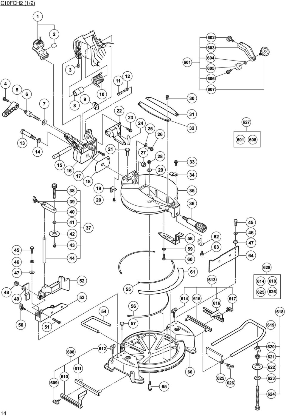
15 C10FCH2 (1/2) A B C D M M M M M M M , 20, M M M M M M M M M M M M M M M M M M M M A B C D M M M M M M M M M M M M , , 618, 625,

16 C10FCH2 (2/2) 16
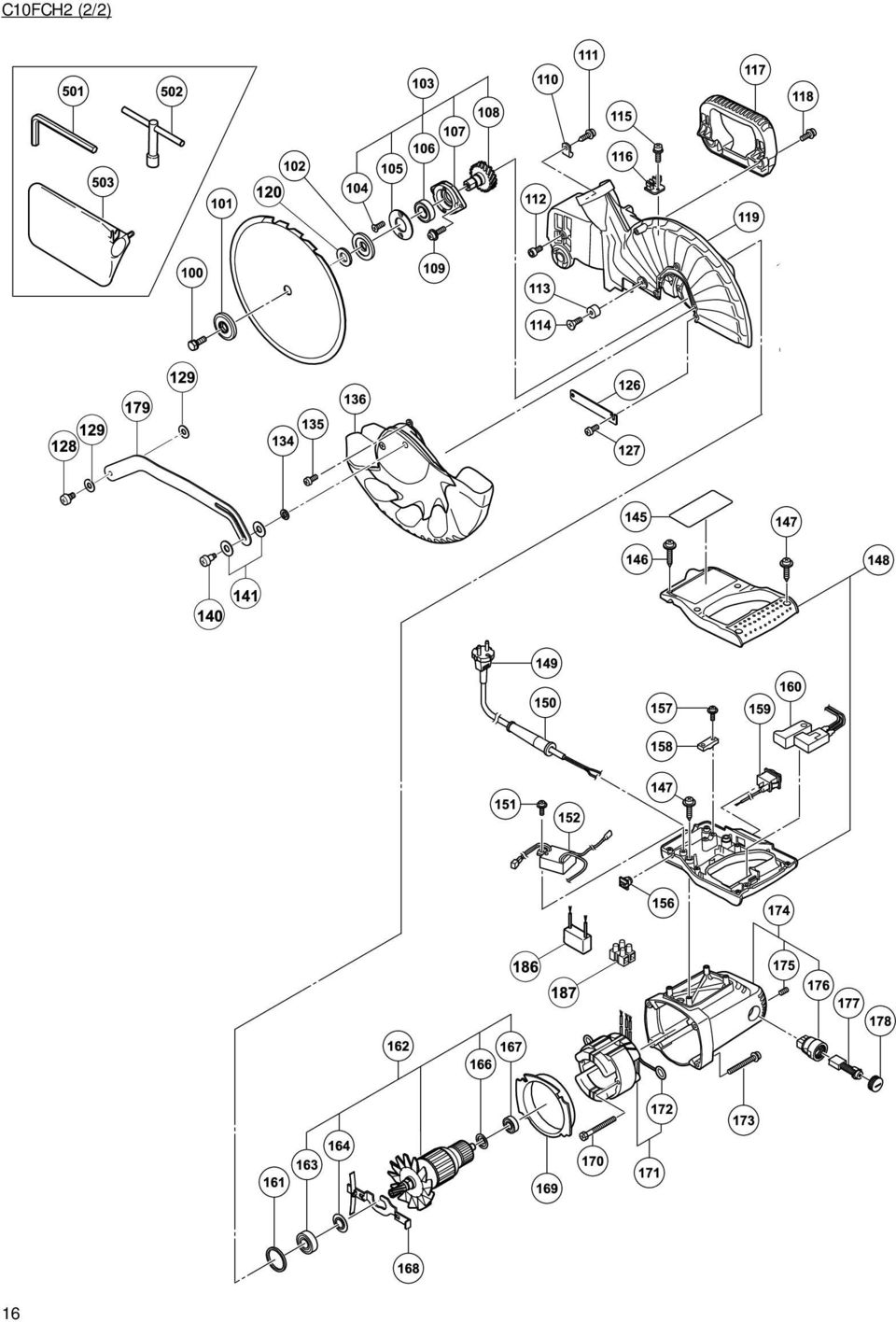
17 C10FCH2 (2/2) A B C D M M VV M M M M M M M M M M M M M M D D D D U 1 110V 163, 164, 166, E 1 230V 163, 164, 166, VV VV D D 1 110V E 1 230V M , M V V A B C D Z

18 C10FCE2 (1/2) 18

19 C10FCE2 (1/2) A B C D M M M M M M M , 20, M M M M M M M M M M M M M M M M M M M M A B C D M M M M M M M M M M M M , , 618, 625,

20 C10FCE2 (2/2) 20

21 C10FCE2 (2/2) A B C D M M VV M M M M M M M M M M M M M D D D U 1 110V 163, 164, 166, E 1 230V 163, 164, 166, VV VV D D 1 110V E 1 230V M , M V V A B C D Z
22 22
23 23
24 Hitachi Koki Co., Ltd. 702 Code No. C Printed in China
Cable Drum Machine. Operation Manual BC260 SERIES. Cleans 1 1/4" to 3" lines up to 50'
 Cable Drum Machine Operation Manual BC260 SERIES Cleans 1 1/4" to 3" lines up to 50' Used For: Sink, Shower & Floor Drains 42FM " WARNING - Read All Instructions, When Using Electric Tools, Basic Safety
Operating instructions Cordless K 10253 impact wrench
 Operating instructions Cordless K 10253 impact wrench Operational precautions General safety instructions warning! 1. Consider work area environment. Do not expose tools to rain. Do not use tools in damp
150W. Bench Grinder. Article number BGM6018. WEB: helpdesk@d u o n s.c o m.a u. After Sales Support TEL: 07 3188 2025 N26968
 150W Bench Grinder INSTRUCTION MANUAL MODEL NUMBER tbg-150 Article number BGM6018 AFTER SALES SUPPORT TEL: 07 3188 2025 WEB: [email protected] After Sales Support TEL: 07 3188 2025 N26968 WEB: helpdesk@d
Auto Feed Screwdriver
 ENGLISH (Original instructions) INSTRUCTION MANUAL Auto Feed Screwdriver 684 00607 DOUBLE INSULATION IMPORTANT: Read Before Using. ENGLISH (Original instructions) SPECIFICATIONS Model 684 Screw strip 4
Mini Pallet Jack OWNER S MANUAL
 Mini Pallet Jack OWNER S MANUAL WARNING: Read carefully and understand all ASSEMBLY AND OPERATION INSTRUCTIONS before operating. Failure to follow the safety rules and other basic safety precautions may
8" BENCH GRINDER OWNER'S MANUAL
 8" BENCH GRINDER OWNER'S MANUAL WARNING: Read carefully and understand all INSTRUCTIONS before operating. Failure to follow the safety rules and other basic safety precautions may result in serious personal
1000-LB. TRAILER JACK OWNER S MANUAL
 1000-LB. TRAILER JACK OWNER S MANUAL WARNING: Read carefully and understand all INSTRUCTIONS before operating. Failure to follow the safety rules and other basic safety precautions may result in serious
ROUTER TABLE INSERT ASSEMBLY AND OPERATING INSTRUCTIONS
 ROUTER TABLE INSERT 94331 ASSEMBLY AND OPERATING INSTRUCTIONS 3491 Mission Oaks Blvd., Camarillo, CA 93011 Visit our Web site at http://www.harborfreight.com Copyright 2006 by Harbor Freight Tools. All
Congratulations on your purchase of the Great Planes SLOT MACHINE, the first truly easy way to cut hinge slots in your model airplanes.
 INSTRUCTION MANUAL Congratulations on your purchase of the Great Planes SLOT MACHINE, the first truly easy way to cut hinge slots in your model airplanes. The Slot Machine you have purchased is equipped
MBSAW. Meat Cutting Band Saw With Meat Grinder Assembly & Operating Instructions
 06/2011 MBSAW Meat Cutting Band Saw With Meat Grinder Assembly & Operating Instructions READ ALL INSTRUCTIONS AND WARNINGS BEFORE USING THIS PRODUCT. This manual provides important information on proper
FJ2. 2 Ton Trolley Floor Jack Assembly & Operating Instructions
 FJ2 2 Ton Trolley Floor Jack Assembly & Operating Instructions READ ALL INSTRUCTIONS AND WARNINGS BEFORE USING THIS PRODUCT. This manual provides important information on proper operation & maintenance.
National- Spencer Inc.
 9-27-2010 National- Spencer Inc. 19.2V HEAVY DUTY GREASE GUN PRODUCT SPECIFICATION Charger Input Power 110 VAC Battery Output Power 19.2V Battery Capacity 1500 MAH Battery Pack Charge Time 1 Hour Maximum
Operating Manual Please Read Before Operating Unit
 Operating Manual Please Read Before Operating Unit Model RT2S Wire Stripper & Component Lead Cleaner Service and All Spare Parts Available The Eraser Company, Inc. PO Box 4961/ Oliva Drive Syracuse, NY
15GAL STEEL OIL DRAIN WITH 110V PUMP
 15GAL STEEL OIL DRAIN WITH 110V PUMP OWNER S MANUAL WARNING: Read carefully and understand all ASSEMBLY AND OPERATION INSTRUCTIONS before operating. Failure to follow the safety rules and other basic safety
Original Assembly Guide
 TCT Multipurpose Single Bevel Sliding Compound Mitre Saw Original Assembly Guide Read instructions before assembling this tool. Table of Contents GB Assembly Guide Read instructions before assembling this
Elo Touch Solutions Wall-mounting Kit for the 5501L IDS Touchmonitors
 Installation Manual Elo Touch Solutions Wall-mounting Kit for the 5501L IDS Touchmonitors SW602206 Rev B Table of Contents Chapter 1: Safety Warning... 3 Chapter 2: Kit Contents... 4 Included in Kit...
758 Heavy-duty Ratchet Guy Wire Cutter
 INSTRUCTION MANUAL 758 Heavy-duty Ratchet Guy Wire Cutter Read and understand all of the instructions and safety information in this manual before operating or servicing this tool. Register this product
AUTHORISED SERVICE AGENTS: CARBA-TEC Pty. Ltd. 40 Harries Road Coorparoo, QLD 4151 Ph: (07) 3397 2577 Fax: (07) 3397 2785
 3397 2577 Fax: (07) 3397 2785") UTHORISED SERVICE GENTS: CR-TEC Pty. Ltd. 40 Harries Road Coorparoo, QLD 4151 Ph: (07) 3397 2577 Fax: (07) 3397 2785 CR-TEC (NSW) Pty. Ltd. 32 Percy Street uburn, NSW 2144 Ph: (02) 9649 5077 Fax: (02)
UTHORISED SERVICE GENTS: CR-TEC Pty. Ltd. 40 Harries Road Coorparoo, QLD 4151 Ph: (07) 3397 2577 Fax: (07) 3397 2785 CR-TEC (NSW) Pty. Ltd. 32 Percy Street uburn, NSW 2144 Ph: (02) 9649 5077 Fax: (02)
CIRCULAR SAW SAFETY Reviewed 9/24/2007
 1. General Safety Rules CIRCULAR SAW SAFETY Reviewed 9/24/2007 DANGER -- Keep hands away from cutting area behind the saw blade since kickback could cause the saw to jump backwards over your hand. Keep
Operating instructions. SCORP 220 Plus SCORP 360. Pipe Cutter. Code 790 014 762 Machine-no.:
 precision. power. simplicity. Operating instructions Pipe Cutter SCORP 220 Plus SCORP 360 Code 790 014 762 Machine-no.: All rights reserved, in particular the rights of duplication and distribution as
COMPOUND SLIDE MITER SAW W - 12 INCH
 COMPOUND SLIDE MITER SAW W - 2 INCH 4288 ASSEMBLY AND OPERATING INSTRUCTIONS 349 Mission Oaks Blvd., Camarillo, CA 930 Visit our Web site at http://www.harborfreight.com Copyright 2002 by Harbor Freight
staple gun with 5/16 Long staples
 staple gun with 5/16 Long staples Model 95718 Assembly And Operation Instructions Due to continuing improvements, actual product may differ slightly from the product described herein. 3491 Mission Oaks
POSEIDON 2-29, 2-25 & 2-22 POSEIDON 2-29, 2-25 & 2-22 XT
 POSEION 2-29, 2-25 & 2-22 POSEION 2-29, 2-25 & 2-22 XT Repair Manual Index A. Safety precautions 3 B. Technical data 4 C. Structure 5-6. Service / Repair 7-23 E. Tools 24 F. Function 25-26 G. Electric
Operation manual. drill rig KERN-DEUDIAM KBS-Series K100
 Operation manual drill rig KERN-DEUDIAM KBS-Series K100 Please read these instructions carefully before starting up the machine to avoid accidents and work interruption. 1. Table of contents 1. Table of
SERVICE PARTS LIST PAGE 1 OF 6 BASE ASSEMBLY SPECIFY CATALOG NO. AND SERIAL NO. WHEN ORDERING PARTS 12" DUAL BEVEL COMPOUND MITER SAW B27A
 PAGE 1 OF 6 BASE ASSEMBLY 00 0 EXAMPLE: Component Parts (Small #) Are Included When Ordering The Assembly (Large #). SPECIFY CATALOG NO. AND NO. WHEN ORDERING PARTS 1 02-80-0050 Thrust Bearing (1) 2 05-80-0510
IMPORTANT SAFETY RULES TO FOLLOW
 WARNING FLOOR & CARPET CLEANER Any piece of equipment can be dangerous if not operated properly. YOU are responsible for the safe operation of this equipment. The operator must carefully read and follow
6 FUNCTION HAMMER DRILL
 6 FUNCTION HAMMER DRILL MODEL NO: CON1500RHD PART NO: 6479508 OPERATION & MAINTENANCE INSTRUCTIONS GC0712 INTRODUCTION Thank you for purchasing this CLARKE 6 Function Hammer Drill. Before attempting to
Machine/Woodworking Shop The Basic Rules
 Machine/Woodworking Shop The Basic Rules 1. Eye protection or face shields are required when working in the shop. A selection of protective goggles and safety glasses are available in the shop. The eyeglasses
tire inflator with pressure gauge
 tire inflator with pressure gauge Model 95583 Assembly And Operation Instructions Due to continuing improvements, actual product may differ slightly from the product described herein. 3491 Mission Oaks
SBC90. Abrasive Blast Cabinet Assembly & Operating Instructions
 SBC90 Abrasive Blast Cabinet Assembly & Operating Instructions READ ALL INSTRUCTIONS AND WARNINGS BEFORE USING THIS PRODUCT. SAVE THESE INSTRUCTIONS FOR FUTURE REFERENCE. This manual provides important
PALLET JACK - 2.5 TON
 PALLET JACK - 2.5 TON 39939 SET UP AND OPERATING INSTRUCTIONS Visit our website at: http://www.harborfreight.com Read this material before using this product. Failure to do so can result in serious injury.
Electric Hoist 44006
 440 lb./ 880 lb. Electric Hoist 44006 SET UP AND OPERATING INSTRUCTIONS Distributed exclusively by Harbor Freight Tools. 3491 Mission Oaks Blvd., Camarillo, CA 93011 Visit our website at: http://www.harborfreight.com
Trillium 40 Axis Spring Tensioner Wire Replacement Instructions
 Trillium 40 Axis Spring Tensioner Wire Replacement Instructions 1 Overview The objective is to replace the broken axis spring tensioner wire. This requires the following tasks: 1. Remove the seismometer
Char-Lynn Hydraulic Motor. Repair Information. 10 000 Series. October, 1997
 Char-Lynn Hydraulic Motor October, 1997 Repair Information Geroler Motor Two Speed 001 27 Retainer inside bore of valve plate bearingless motors only 4 15 16 3 6 35 Parts Drawing 25 2 2 1 19 17 36 40 47
HYDRAULIC TABLE CART 500-LB.
 HYDRAULIC TABLE CART 500-LB. OWNER S MANUAL WARNING: Read carefully and understand all MACHINE ADJUSTMENT AND OPERATION INSTRUCTIONS before operating. Failure to follow the safety rules and other basic
Notes. Material 1. Tools the employee is expected to operate
 OSHA Standard29 CFR 1910.211-.247, Subpart O, Machinery and Machine Guarding, and Subpart P, Hand and Portable-Powered Tools and other Hand- Held Equipment. Hand Tool Safety Preparation 1. Read Applicable
Resharpening Companion
 Resharpening Companion 10950 Correct Angles, Pictures, and Step-By-Step Instructions The Resharpening Companion is meant to be a guide and quick reference to help you resharpen. It is not meant to replace
Responsibilities of a Volunteer Leader
 Responsibilities of a Volunteer Leader Inspecting tools for safe conditions. Removing unsafe tools from use and immediately notifying site supervisor. Teaching safe tool use to volunteers on your crew.
Sport Ice Elektro 124
 Sport Ice Elektro 124 Operation Manual 2007/4 V2.1 Introduction The Sport Ice Elektro 124 is an ice resurfacing machine designed to be used on small ice surfaces. The machine has been designed to produce
OWNER S MANUAL Table Tennis Table Patent Pending
 OWNER S MANUAL Table Tennis Table Patent Pending Be sure to write your model number and serial number here for future reference. You can find these numbers printed on the bottom of the table. MODEL # T8179
DO NOT OPERATE LANCELOT OR SQUIRE WITHOUT FIRST ADJUSTING THE SAFETY GUARD. ( See Below)
") Assembly Instructions - Lancelot and Squire King Arthur s Tools (KAT) is pleased to present the first tandem mounted saw chain accessories whereby differing combinations of Lancelot and Squire may be paired
Assembly Instructions - Lancelot and Squire King Arthur s Tools (KAT) is pleased to present the first tandem mounted saw chain accessories whereby differing combinations of Lancelot and Squire may be paired
2006 HEADSHOK Service Video #1
 LEFTY SPEED DLR DAMPING CARTRIDGE This document explains how to properly remove, disassemble, inspect, reassemble and reinstall the Lefty Speed DLR2 damping cartridge. It is a document to be used in conjunction
3/4 PIPE CLAMP WITH STAND
 3/4 PIPE CLAMP WITH STAND Model 94053 ASSEMBLY AND OPERATING INSTRUCTIONS (3/4 DIAMETER PIPE NOT INCLUDED.) 3491 Mission Oaks Blvd., Camarillo, CA 93011 Visit our Web site at: http://www.harborfreight.com
Speed-Mat Rectangle Cutter
 Speed-Mat Rectangle Cutter 1 Honeycomb baseboard. 2 Left hold down. 14 3 Bottom hold down. 4 4 Left / right rule. 8 5 8 5 Left / right rule pointer. 1 6 Top / bottom rule. 7 Top / bottom rule pointer.
www.blackanddecker.co.uk Ireland Australia New Zealand
 www.blackanddecker.co.uk 8 6 7 5 3 4 1 2 UK Ireland Australia New Zealand 9 8 A 7 10 6 11 13 12 6 11 B C 16 14 15 17 5 D 2 13 E 8 9 F 3 Intended use Your Black & Decker rotary hammer drill has been designed
TECHNICAL INFORMATION
 TECHNICAL INFORMATION Models No. 2012NB Description 304mm (12") Automatic Thickness Planer CONCEPTION AND MAIN APPLICATIONS * Compact and light weight (27 Kg./59 lbs) automatic thickness planer for easier
Owner s Manual Gantry Cranes
 Owner s Manual Gantry Cranes Fixed Height Gantry Crane MODEL NUMBER: SERIAL NUMBER: CAPACITY IN TONS: Telescoping Gantry Crane Bushman AvonTec 262-790-4200, 800338-7810, Fax 262-790-4200 www.bushmanavontec.com
Alfra Rotabest 100 Metal Core Drilling Machine. Operation Manual
 Alfra Rotabest 100 Metal Core Drilling Machine Operation Manual 06/2005 1. Technical Data Prod. No.: 18630 Name : Rotabest 100 Input: Load rpm: 1800 Watt 110/175/245/385 rpm Tool Holder : MT 3 Coolant
Active and Passive Sash Replacement
 for Andersen Gliding Windows Read all instructions carefully before attempting this procedure. If you have any questions about your ability to complete the procedure, call Andersen at 1-888-888-7020 for
Electric Meat Grinder
 Electric Meat Grinder OWNER S MANUAL WARNING: Read carefully and understand all INSTRUCTIONS before operating. Failure to follow the safety rules and other basic safety precautions may result in serious
Cordless Circular Saw
 ENGLISH (Original instructions) INSTRUCTION MANUAL Cordless Circular Saw DSS60 DSS6 006699 IMPORTANT: Read Before Using. ENGLISH (Original instructions) SPECIFICATIONS Model DSS60 DSS6 Blade diameter 65
Pet hair clipper. Model 96822. Diagrams within this manual may not be drawn proportionally.
 Pet hair clipper Model 96822 Cleaning And Operation Instructions Diagrams within this manual may not be drawn proportionally. Due to continuing improvements, actual product may differ slightly from the
GGS 27 GGS 27 C PROFESSIONAL
 GGS 27 GGS 27 C * Des idées en action. Bedienungsanleitung Operating instructions Instructions d emploi Instrucciones de servicio Manual de instruções Istruzioni d uso Gebruiksaanwijzing Betjeningsvejledning
Instruction Manual. Image of SP-3015 & SP-3815. Important Safeguards. Automatic Dispensing Hot Water Pot with Reboil Function
 Important Safeguards READ ALL INSTRUCTIONS BEFORE USE. Instruction Manual Automatic Dispensing Hot Water Pot with Reboil Function Image of SP-3015 & SP-3815 SP-3015: 3.0L SP-3815: 3.8L SP-3017: 3.0L (Stainless
ECO-SHREDDER BY DUROSTAR OWNERS OPERATING MANUAL CHIPPER / SHREDDER / MULCHER MODEL ES1600
 ECO-SHREDDER BY DUROSTAR OWNERS OPERATING MANUAL CHIPPER / SHREDDER / MULCHER MODEL ES1600 SPECIFICATIONS: Horse Power: 2.5HP HopperSize: 15-1/4" x 10-3/8" Side Chute: 1-3/8" x 2-5/16" R.P.M: 3450 THANK
TRIMMING UNIT/DIAMOND MACHINE TST.13
 TRIMMING UNIT/DIAMOND MACHINE TST.13 REFERENCE BOOK rel. 02.15 TRIMMING UNIT/DIAMOND MACHINE TST.13 REL. 02.15 ENGLISH LANGUAGE 1 MACHINE DESCRIPTION TST.13 was designed and built for processing methacrylate.
RL HW / RL HW+ / RL HGW / RL HV / RL HVPW/RL HVPW-G
 Auto-Levelling Rotary Laser Level RL HW / RL HW+ / RL HGW / RL HV / RL HVPW/RL HVPW-G 77-496 / 77-429 / 77-439 / 77-497 / 77-427/ 77-441 Please read these instructions before operating the product Auto-Levelling
Router. A. Identify the major parts of the router. B. Complete a written test on safety and operating procedures of the router with 100% accuracy.
 Router I. Competencies Given a properly adjusted router, instruction and demonstration of use, each student will be able to: A. Identify the major parts of the router. B. Complete a written test on safety
ATS Overhead Table Shelf System INSTRUCTION MANUAL
 ATS Overhead Table Shelf System INSTRUCTION MANUAL ATS Overhead Table Shelf System Instruction Manual Warranty Newport Corporation warrants this product to be free of defects in material and workmanship
INSTALLATION INSTRUCTIONS for Bifold Doors (JII103)
") Thank you for selecting JELD-WEN products. Attached are JELD-WEN s recommended installation instructions for premium composite, hollow and solid core molded Bifold Doors. Bifolds are designed for fast
Thank you for selecting JELD-WEN products. Attached are JELD-WEN s recommended installation instructions for premium composite, hollow and solid core molded Bifold Doors. Bifolds are designed for fast
PRODUCT MANUAL - M090
 PRODUCT MANUAL - M090 MODEL 203/266 ELECTRIC CAN OPENER 1 SAFETY CAUTION: SEVERED CAN LIDS HAVE CUTTING EDGES. USE OF A PROTECTIVE GLOVE OR TONGS IS ADVISED WHEN HANDLING LIDS. WARNING To avoid risk of
Abrasive Wheel Grinder Safety
 Abrasive Wheel Grinder Safety One of the most common pieces of machinery in use in the maintenance shops on campus is the abrasive wheel grinder. These useful machines, used to remove metal from flat and
MODEL T200-F18 MODEL T125-F18 Finish Nailers
 P MODEL T200-F18 MODEL T125-F18 Finish Nailers IMPORTANT! DO NOT DESTROY It is the customer s responsibility to have all operators and service personnel read and understand this manual. OPERATING MANUAL
TABLE SAW. 250mm (10") 1500W INSTRUCTION MANUAL SPECIFICATIONS. ozito.com.au TSF-1210 WHAT S IN THE BOX. Rip Fence. Sliding Mitre Gauge
 1500W INSTRUCTION MANUAL SPECIFICATIONS. ozito.com.au TSF-1210 WHAT S IN THE BOX. Rip Fence. Sliding Mitre Gauge") WHAT S IN THE BOX TABLE SAW 250mm (10") 1500W INSTRUCTION MANUAL SPECIFICATIONS Motor: 1500W (S6 40%) Input: 230-240V ~ 50Hz No Load Speed: 5,700/min Blade: Ø250mm x Ø30 x 2.4mm Bevel Angle: 0-45 left
WHAT S IN THE BOX TABLE SAW 250mm (10") 1500W INSTRUCTION MANUAL SPECIFICATIONS Motor: 1500W (S6 40%) Input: 230-240V ~ 50Hz No Load Speed: 5,700/min Blade: Ø250mm x Ø30 x 2.4mm Bevel Angle: 0-45 left
SAFETY & OPERATING INSTRUCTIONS
 SAFETY & OPERATING INSTRUCTIONS EDLUND TOMATO LASER, Models ETL -316, -140 & -380 READ AND UNDERSTAND THIS MANUAL AND ALL INSTRUCTIONS BEFORE OPERATING THIS SLICER. 159 Industrial Parkway, Burlington,
48 INCH PAN AND BRAKE BOX
 Thank you very much for choosing a Klutch product. For future reference, please complete the owner s record below: Serial Number/Lot Date Code: Purchase Date: Save the receipt, warranty and these instructions.
Packaged Terminal Air Conditioner Wall Sleeve Installation
 Installation & Maintenance Data IM 1196 Group: PTAC Part Number: 910141799 Date: October 2013 Packaged Terminal Air Conditioner Installation x 42" PGAN with Top-Mounted Hydronic Heat Note: Installation
ENGLISH (Original instructions) INSTRUCTION MANUAL. Jig Saw DOUBLE INSULATION. IMPORTANT: Read Before Using.
 INSTRUCTION MANUAL. Jig Saw DOUBLE INSULATION. IMPORTANT: Read Before Using.") ENGLISH (Original instructions) INSTRUCTION MANUAL Jig Saw 46 47 48 49 00808 DOUBLE INSULATION IMPORTANT: Read Before Using. ENGLISH (Original instructions) SPECIFICATIONS Max. cutting capacities Model
ENGLISH (Original instructions) INSTRUCTION MANUAL Jig Saw 46 47 48 49 00808 DOUBLE INSULATION IMPORTANT: Read Before Using. ENGLISH (Original instructions) SPECIFICATIONS Max. cutting capacities Model
1-800-295-5510 uline.com SPECIFICATIONS
 H-1394, H-1395, H-1396 H-1397, H-3859, H-3860 π GRAVITY CONVEYOR 1-800-295-5510 uline.com SPECIFICATIONS Conveyor Bed Width In (mm) 18, 24, 30 (457, 610, 762) Load Capacity Per Linear Foot (305mm) Lbs
Owners & Installation Manual for the Sheridan, Mountainair, Pine Valley and Old Forge Ceiling Fan Family
 Owners & Installation Manual for the Sheridan, Mountainair, Pine Valley and Old Forge Ceiling Fan Family Part of the Kiva Lighting Family Custom Lighting and Fans Since 1992 1312 12th St NW Albuquerque,
For exploded diagram and part number information, refer to the Spare Parts Catalog available on our website at www.rockshox.com.
 For exploded diagram and part number information, refer to the Spare Parts Catalog available on our website at www.rockshox.com. 2 0 0 5 D U K E A I R X C / S L / R A C E S E R V I C E G U I D E Information
Remote Head REMO ONE. Code 5750. Manual
 Remote Head REMO ONE Code 5750 Manual by sachtler. All rights reserved Version: 1.2/09/05 Issue date: September 2005 Order no.: srh20t010a We want you to receive Sachtler products that are always state
SECTION G2: CABLE PROCESSOR MODULE MAINTENANCE
 SECTION G2: CABLE PROCESSOR MODULE MAINTENANCE Cable Processor Module overview WARNING! When tipping the Cable Processor Module back, (after removing the toggle arm pin), use extreme caution not to drop
PNEUMATIC PLANISHING HAMMER
 PNEUMATIC PLANISHING HAMMER 94847 ASSEMBLY AND OPERATING INSTRUCTIONS Due to continuing improvements, actual product may differ slightly from the product described herein. Distributed Exclusively by Harbor
OPERATING INSTRUCTIONS FOR
 OPERATING INSTRUCTIONS FOR MEDECO KEY MACHINES FOR MEDECO ORIGINAL, BIAXIAL, MEDECO 3, KEYMARK CLASSIC & KEYMARK X4 PRODUCTS MEDECO HIGH SECURITY LOCKS ASSUMES NO RESPONSIBILITY FOR INJURY OR PROPERTY
PEDAL CAR - GO CART ASSEMBLY & OPERATING INSTRUCTIONS
 PEDAL CAR - GO CART 42822 ASSEMBLY & OPERATING INSTRUCTIONS 3491 Mission Oaks Blvd., Camarillo, CA 93011 Visit our Web site at: http://www.harborfreight.com Copyright 2000 by Harbor Freight Tools. All
Copyright Black & Decker
 KC9024FB1 2 Copyright Black & Decker 5 2 1 3 4 A 6 2 B 3 3 7 C D 1 8 E 4 CORDLESS SCREWDRIVER KC9024FB ENGLISH CONGRATULATIONS! You have chosen a Black & Decker tool. Our aim is to provide quality tools
LU6X-130 Instructions and Parts List (including LU6X Basic) Operating Instructions
 Operating Instructions") LORTONE LU6X-130 Item # 061-092 LU6X Basic Item # 061-090 LU6X-130 Instructions and Parts List (including LU6X Basic) Operating Instructions Introduction The LU6X is one the most versatile pieces of equipment
LORTONE LU6X-130 Item # 061-092 LU6X Basic Item # 061-090 LU6X-130 Instructions and Parts List (including LU6X Basic) Operating Instructions Introduction The LU6X is one the most versatile pieces of equipment
OPERATOR S MANUAL 18 VOLT, 1 HOUR CHARGER
 OPERATOR S MANUAL 18 VOLT, 1 HOUR CHARGER P110 Your battery charger has been engineered and manufactured to Ryobi s high standard for dependability, ease of operation, and operator safety. When properly
Service Manual Rol-Lift
 R 2000 Service Manual Rol-Lift Series: T and E Developed by Generic Parts Service This manual is intended for basic service and maintenance of the Rol-Lift pallet jack. The pallet jacks you are servicing
Instructions and precautions. Fork Height. Visit our website at: http://www.harborfreight.com
 Pallet Jack Item 68760 / 68761 Instructions and precautions Specifications Capacity Control Lever Fork Height Fork Length Fork Width Maximum Minimum Width over Forks Steering Wheel Dia. 2-1/2 Ton (5,000
Multi-Pitch Pitching Machine USER MANUAL
 Multi-Pitch Pitching Machine USER MANUAL TABLE OF CONTENTS Thank you for purchasing the Cimarron Multi-Pitch Pitching Machine. The Cimarron Multi-Pitch Pitching Machine is a high performance pitching machine
COMPACT ELITE MAT CUTTER
 INSTRUCTION MANUAL MODEL 350-1 COMPACT ELITE MAT CUTTER INSTRUCTIONS AND OPERATION MANUAL 32in (81cm) mat cutting system with bevel & straight cutters, production stops and 20 in (51 cm) squaring bar.
1 Ton Telescoping Gantry Crane
 1 Ton Telescoping Gantry Crane 41188 Gantry Crane Read this material before using this product. Failure to do so can result in serious injury. SAVE THIS MANUAL. When unpacking, make sure that the product
DIAMOND Retractable Rodding Robot Model SPRAYROD-R
 2004-12-21 2 1 (23) DIAMOND Retractable Rodding Robot Model SPRAYROD-R 2004-12-21 2 2 (23) Table of contents 1 TECHNICAL DESCRIPTION...4 1.1 MAIN DETAILS...5 1.2 COMPONENTS DESCRIPTION...5 1.2.1 Pneumatic
Router Table Plans. www.bobsplans.com
 www.bobsplans.com Router Table Plans Increase the capabilities of your router with this weekend project. Features a sliding fence with EZ-Mount clamps. These clamps are simple to make and grip tightly
Small Flat Panel Lift Arm FSA-1004 and KSA-1004
 I N S T A L L A T I O N I N S T R U C T I O N S Small Flat Panel Lift Arm FSA-1004 and KSA-1004 The Lift Arm is an accessory that can be used with a broad range of Small Flat Panel Displays. The allows
Flat Bottom Long Ram Hydraulic Jack
 Flat Bottom Long Ram Hydraulic Jack 3 Ton 8 Ton 36468 36469 ASSEMBLY & OPERATING INSTRUCTIONS 349 Mission Oaks Blvd., Camarillo, CA 930 Visit our Web site at http://www.harborfreight.com TO PREVENT SERIOUS
1100 LB. ELECTRIC HOIST
 1100 LB. ELECTRIC HOIST 93251 ASSEMBLY AND OPERATING INSTRUCTIONS Jib Boom not included. Diagrams within this manual may not be drawn proportionally. Due to continuing improvements, actual product may
Tech Shop Safety Level 2 - FN000425. Tech Shop / Tool Safety Operations. (Fermilab machines not covered in course FN000258)
") Tech Shop Safety Level 2 - FN000425 Tech Shop / Tool Safety Operations (Fermilab machines not covered in course FN000258) Table of Contents Tech Shop / Tool Safety Operations 3 General Rules of Safety
Tech Shop Safety Level 2 - FN000425 Tech Shop / Tool Safety Operations (Fermilab machines not covered in course FN000258) Table of Contents Tech Shop / Tool Safety Operations 3 General Rules of Safety
Installation Instructions
 Installation Instructions READ BEFORE INSTALLING UNIT For Low Profile Window Air Conditioner INSTALLATION WARNINGS AND CAUTION Carefully read the installation manual before beginning. Follow each step
National Optical & Scientific Instruments Inc. 11113 Landmark 35 Drive San Antonio, Texas 78233 Phone (210) 590-9010 Fax (210) 590-1104
 590-9010 Fax (210) 590-1104") National Optical & Scientific Instruments Inc. 11113 Landmark 35 Drive San Antonio, Texas 78233 Phone (210) 590-9010 Fax (210) 590-1104 INSTRUCTIONS FOR MODELS 106, 106-L 107, 107-L 108, 108-L 109-L ELEMENTARY
National Optical & Scientific Instruments Inc. 11113 Landmark 35 Drive San Antonio, Texas 78233 Phone (210) 590-9010 Fax (210) 590-1104 INSTRUCTIONS FOR MODELS 106, 106-L 107, 107-L 108, 108-L 109-L ELEMENTARY
MODEL E-AF. Drain Cleaning Machine. Operator s Manual
 MODEL E-AF Drain Cleaning Machine Operator s Manual!!!! FOR YOUR SAFETY Before you operate or maintenance this equipment, READ this manual carefully and completely! Purchase Date: Serial Number: ELECTRIC
Router Table. Operating Procedures for
 Operating Procedures for Router Table INTRODUCTION: The router table is a very versatile tool. It can be used to cut a molding profile, cut workpieces to match the shape of a pattern and cut a molding
Industrial Process Pump Safety Manual IMPORTANT SAFETY NOTICE
 Industrial Process Pump Safety Manual IMPORTANT SAFETY NOTICE To: Our Valued Customers User safety is a major focus in the design of our products. Following the precautions outlined in this manual will
M4 DRILL STAND INSTRUCTIONS
 M4 DRILL STAND INSTRUCTIONS REIMANN & GEORGER CORPORATION CONSTRUCTION PRODUCTS BUFFALO, NY P/N 6122052 8/15/00 TABLE OF CONTENTS CHAPTER TITLE PAGE 1 SAFETY...1 1.1 Introduction...1 1.2 Safety Definitions...1
English. Symbols used to mark instructions...3. Congratulations...5 Getting the best results...5. Warnings...6 Operating Procedure...
 2 Contents Components Attachments Guidance Installation Operation Maintenance Service Technical Troubleshooting Symbols used to mark instructions...3 Included Attachments...4 Congratulations...5 Getting
National Optical & Scientific Instrument Inc. 11113 Landmark 35 Drive San Antonio, Texas 78233 Phone (210) 590-9010 Fax (210) 590-1104
 590-9010 Fax (210) 590-1104") National Optical & Scientific Instrument Inc. 11113 Landmark 35 Drive San Antonio, Texas 78233 Phone (210) 590-9010 Fax (210) 590-1104 INSTRUCTIONS FOR STEREOSCOPIC MICROSCOPES MODEL NUMBERS 400 400TL
National Optical & Scientific Instrument Inc. 11113 Landmark 35 Drive San Antonio, Texas 78233 Phone (210) 590-9010 Fax (210) 590-1104 INSTRUCTIONS FOR STEREOSCOPIC MICROSCOPES MODEL NUMBERS 400 400TL
Operation and Safety Manual GPR. Belt Driven Slicers. Light Duty; Belt-Driven; Manual Operation
 Operation and Safety Manual Light Duty; Belt-Driven; Manual Operation GPR Belt Driven Slicers Operation and Safety Manual DO NOT ATTEMPT TO OPERATE THIS MACHINE UNTIL YOU HAVE READ AND UNDERSTOOD THIS
Installation Instructions For Slider Casement Air Conditioners
 Installation Instructions For Slider Casement Air Conditioners NOTE: These instructions describe installation in a typical wood framed window with a wood SLIDE-BY sash, or installation in a metal CASEMENT