DTC1000 / DTC1000M / DTC4000 User Guide
|
|
|
- Steven Powers
- 10 years ago
- Views:
Transcription
1 15370 Barranca Parkway Irvine, CA USA DTC1000 / DTC1000M / DTC4000 User Guide P/N: L001398, Revision 1.5

2 DTC1000/DTC1000M/DTC4000 Card Printer/Encoder User Guide (Rev. 1.5), 2012 property of HID Global Corporation. All rights reserved. Exclusive permission is granted to authorized resellers of HID Global products to reproduce and distribute this copyrighted document to authorized HID Global customers, who have signed a no disclosure agreement regarding the restricted, proprietary use of said document. The revision number for this document will be updated to reflect changes, corrections, updates and enhancements to this document. Revision Control Number Date Document Title Revision 1.5 March 2012 DTC1000/DTC1000M/DTC4000 Card Printer/Encoder User Guide DTC1000M Revision 1.4 Xxxx 2011 DTC1000/DTC4000 Card Printer/Encoder User Guide Revision 1.3 January 2011 DTC1000/DTC4000 #44 Flipper Table Level (Troubleshooting with the Error Message Table) Added Connecting the Printer power Power Supply Efficiency Level V minimum (Regulatory Compliances) Card Printer/Encoder User Guide Revision 1.2 August 2010 DTC1000/DTC4000 Card Printer/Encoder User Guide Trademarks and Disclaimers HID, HID Global, and Fargo are the trademarks or registered trademarks of HID Global Corporation in the U.S. and other countries. The information contained in this document is provided AS IS without any warranty. HID Global hereby disclaims all warranties and conditions with regard to the information contained herein, including all implied warranties of merchantability, fitness for a particular purpose, title and non-infringement. In no event shall HID Global be liable, whether in contract, tort or otherwise for any indirect, special or consequential damages arising from the use of the information contained in this document. Any questions regarding changes, corrections, updates or enhancements to this document should be forwarded to: Hid Global-Support Services 6533 Flying Cloud Drive Eden Prairie, MN (USA) (866) Ext #6 FAX: (952)

3 Table of Contents DTC1000 / DTC1000M / DTC4000 User Guide 1 Section 1: Specifications 5 Regulatory Compliances 5 Agency Listings 6 United States 6 Canada 6 Environmental Protection (China-RoHS) 7 Traditional Chinese RF Emissions and Safety Statements 7 Simplified Chinese 8 Safety Messages (review carefully) 9 Technical Specifications 10 Functional Specifications 14 Printer Components: Print Ribbons 14 Ribbon Types/Count Table 15 Printer Components: Blank Cards 16 Section 2: Setup and Installation Procedures 17 Choosing a Good Location 17 About Moisture Condensation 17 Unpacking and Inspection 17 Installing the Print Ribbon Cartridge (DTC1000/DTC1000M, and DTC4000) 18 Installing the Ribbon 19 Installing Blank Cards into the Card Hopper (DTC1000, DTC1000M, and DTC4000) 21 Setting the Card Size for CR79 and CR80 23 Connecting the Printer power 27 Section 3: Print Driver Installation 28 Driver Installation Instructions 29 Swift ID Installation Instructions 31 Installing Swift ID 33 Printer Installed On Network 34 Printer Connected Via USB Connection 36 Option No Option No Uninstalling Swift ID 37 Additional Swift ID Rules 37 Section 4: Printer Preferences Tab Functions 38 Using the Card tab 38 Using the Toolbox Options 40 Using the Configuration tab 41 Using the Event Monitoring Group Box 41 Using the Calibrate Ribbon tab 42 Using the Clean Printer tab 43 Using the Advanced Settings tab 45 Using the Device Options tab 54 Using the Image Color tab 58 Using the Image Calibrate tab 61 Using the Magnetic Encoding Tab 62 3
 18 Installing the Ribbon 19 Installing Blank Cards into the Card Hopper (DTC1000, DTC1000M, and DTC4000) 21 Setting")
4 Using the Magnetic Encoding Tab ISO Standards 63 Using the Magnetic Encoding Tab Custom Encoding or Raw Binary Encoding Mode 65 Reviewing the ISO Track Locations 66 Reviewing the Sample String 67 Sending the Track Information 68 Reviewing the ASCII Code and Character Table 69 Using the Overlay / Print Area tab 71 Using the K Panel Resin tab 74 Using the Printer Info tab 77 Section 5: Selecting the Fluorescent Panel Ribbon Type (DTC4000 only) 78 Creating a Custom Fluorescent Image (using the YMCFKO Ribbon) 78 Configuring Fluorescent Data (F-Panel for YMCFKO Ribbon) using the Application 80 Section 6: System Overview- Troubleshooting 84 Reviewing the DTC1000/DTC1000M/DTC4000 Sequence of Operations 84 Section 7: Troubleshooting 86 Printer Error Button and Display Message Table 86 Using the Error Message Table 88 Troubleshooting with the Error Message Table 89 Printer Specific Tools (DTC1000/DTC4000) 97 Additional Printer Specific Tools 99 Section 8: Cleaning 101 Safety Messages (review carefully) 101 DTC1000, DTC1000M, and DTC4000 Card Printer/Encoders Cleaning Kit 102 Supplies (included with the Cleaning Kit) 102 Printhead Cleaning 103 Cleaning the Platen and the Card Feed Rollers 104 Cleaning the Printer s Exterior 108 Section 9: Firmware Upgrades 109 Upgrade the Printer Firmware 109 Section 10: HID Global Technical Support 112 Reading the Serial Numbers on a Fargo Printer 113 Appendix A 114 Using the Defined Area Option 114 Configuring Fluorescent Data (F-Panel for YMCFKO Ribbon) using the Workbench 115 4

5 Section 1: Specifications The purpose of this section is to provide you with specific information on the Regulatory Compliances, Agency Listings, Technical Specifications and Functional Specifications for the DTC1000/DTC1000M/DTC4000 Card Printer User Guide. Regulatory Compliances Term UL CSA (cul) FCC CE Environmental Description The Card Printer is listed under UL (2 nd edition) INFORMATION TECHNOLOGY EQUIPMENT Note: This product is intended to be supplied by a Listed Power Unit marked Class 2 and rated for 24 V dc, 3.3A minimum The Printer manufacturer has been authorized by UL to represent the Card Printer as CSA Certified under CSA Standard C22.2 IEC nd edition File Number: E The Card Printer complies with the requirements in Part 15 of the FCC rules for a Class A digital device. The Card Printer has been tested and complies with EN , EN , EN , and EN : All:2009 (Note: Based on the above testing, the Printer manufacturer certifies that the Card Printer complies with the following directives of the European Community and has placed the CE mark on the Card Printer.) LVD 2006/95/EC, EMC 2004/108/EC, R+TTE 1999/5/EC, ROHS 2002/95/EC Power supply Efficiency level V minimum. RoHS, China RoHS 5

6 Agency Listings Term Emissions Standards Safety Standards Additional Agency Listings Description FCC Part 15 Class A, RSS-GEN, RSS 210, CNS 13438, CNS 14336, EMC 2004/108/EC, R&TTE 1999/95/EC,GB , GB UL IEC (2 nd edition), CSA C22.2 No LVD 2006/95/EC, GB4943 CCC, BSMI, KCC United States This device complies with Part 15 of the FCC rules. Operation is subject to the following two conditions: (1) This device may not cause harmful interference. (2) This device must accept any interference received, including interference that may cause undesired operation. Note: This equipment has been tested and found to comply with the limits for a Class A digital device, pursuant to part 15 of the FCC Rules. These limits are designed to provide reasonable protection against harmful interference when the equipment is operated in a commercial environment. This equipment generates, uses, and can radiate radio frequency energy and, if not installed and used in accordance with the instruction manual, may cause harmful interference to radio communications. Operation of this equipment in a residential area is likely to cause harmful interference; in which case, you will be required to correct the interference at his own expense. Canada This Class A digital apparatus complies with Canadian ICES-003. C et appareil numerique de la classe A est comforme a la norme NMB-003 du Canada. Caution: Changes or modifications not expressly approved by the party responsible for compliance could void the user s authority to operate the equipment. 6
 This device must accept any interference received, including interference that may cause undesired operation.")
7 Environmental Protection (China-RoHS) Environmental Protection Use Period is based on the product being used in an office environment. Traditional Chinese RF Emissions and Safety Statements 7


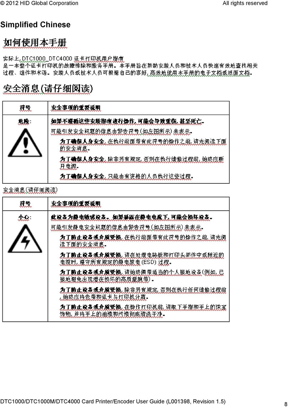
8 Simplified Chinese 8
9 Safety Messages (review carefully) Symbol Danger: Caution: Critical Instructions for Safety purposes Failure to follow these installation guidelines can result in death or serious injury. Information that raises potential safety issues is indicated by a warning symbol (as shown to the left). To prevent personal injury, refer to the following safety messages before performing an operation preceded by this symbol. To prevent personal injury, always remove the power cord prior to performing repair procedures, unless otherwise specified. To prevent personal injury, make sure only qualified personnel perform these procedures. This device is electrostatically sensitive. It may be damaged if exposed to static electricity discharges. Information that raises potential electrostatic safety issues is indicated by a warning symbol (as shown to the left). To prevent equipment or media damage, refer to the following safety messages before performing an operation preceded by this symbol. To prevent equipment or media damage, observe all established Electrostatic Discharge (ESD) procedures while handling cables in or near the Circuit Board and Printhead Assemblies. To prevent equipment or media damage, always wear an appropriate personal grounding device (e.g., a high quality wrist strap grounded to avoid potential damage). To prevent equipment or media damage, always remove the Ribbon and Cards from the Printer before making any repairs, unless otherwise specified. To prevent equipment or media damage, take jewelry off of fingers and hands, as well as thoroughly clean hands to remove oil and debris before working on the Printer. 9

10 Technical Specifications Term Print Method Print resolution Colors Print Ribbon Options Function Dye Sublimation / Resin Thermal Transfer 300 dpi (11.8 dots/mm); continuous tone Up to 16.7 million colors / 256 shades per pixel Full-color with resin black and overlay panel, YMCKO*, 250 prints Full-color half-panel with resin black and overlay panel, YMCKO*, 350 prints Full-color with two resin black panels and overlay panel, YMCKOK*, 200 prints Full-color with fluorescing, two resin black panels and overlay panel, YMCFKO*, 200 prints Full-color with fluorescing, two resin black panels and overlay panel, YMCFKOK*, 175 prints Resin black and overlay panel, KO*, 500 prints Dye-sublimation black and overlay print, BO*, 500 prints Resin black (standard and premium), 1000 prints Resin green, blue, red, white, silver and gold, 1000 prints Rewrite technology No ribbon is required * Indicates the Ribbon type and the number of Ribbon panels printed where Y=Yellow, M=Magenta, C=Cyan, K=Resin Black, O=Overlay, F=Fluorescing Resin 10
, 1000 prints")
11 Technical Specifications Term Print Speed Card Size and Types Supported Accepted Standard Card Sizes Accepted Card Thickness Accepted Card Types Function 7 seconds per card (K*) 12 seconds per card (KO*) 24 seconds per card (YMCKO*) 31 seconds per card (YMCKOK*) Print speed indicates an approximate batch print speed and is measured from the time a card feeds into the Printer to the time it ejects from the Printer. Print speeds do not include encoding time or the time needed for the PC to process the image. Process time is dependent on the size of the file, the CPU, amount of RAM and the amount of available resources at the time of the print. * Indicates the Ribbon type and the number of Ribbon panels printed where Y=Yellow, M=Magenta, C=Cyan, K=Resin Black, O=Overlay, F=Fluorescing Resin CR-80 (3.375"L x 2.125"W / 85.6mmL x 54mmW) CR-79 (3.313 L x W / 84.1mmL x 52.4mmW CR-80 edge-to-edge (3.36"L x 2.11"W / 85.3mmL x 53.7mmW) CR-79 (3.3 L x 2.04 W / 83.8mmL x 51.8mmW) / 9 mil 40 mil /.229mm 1.016mm PVC or polyester cards with polished PVC finish; monochrome resin required for 100% polyester cards; optical memory cards with PVC finish; rewrite 11

12 Technical Specifications Term Input Hopper Card Capacity Output Hopper Card Capacity Reject Hopper Card Capacity Card Cleaning Printer Memory Function 100 cards (.030 /.762.mm) DTC1000, DTC1000M, DTC cards (.030 /.762 mm) DTC4000 (Dual Hopper) 100 cards (.030 /.762.mm) DTC cards (.030 /.762.mm) DTC cards (.030 /.762.mm) same-side Input/Output Card Hopper (required) Card cleaning roller integrated into the Ribbon Cartridge. A new cleaning roller is included with each Ribbon Cartridge. 32MB RAM Software Driver Windows XP / Vista (32 bit & 64 bit) / Server 2003 & 2008 / Windows 7 (32 bit & 64 bit) / Linux Interface Operating Temperature Humidity Dimensions Weight Agency Listings USB 2.0 and Ethernet with internal print server 65 degrees to 80 degrees F / 18 degrees to 27 degrees C 20-80% non-condensing Here are the dimensions for the DTC1000: Single-Sided Printer: 8.8 H x 13.7 W x 7.9 D / 224mmH x 348mmW x 201mmD (DTC1000M) Dual-Sided Printer: 9.8 H x 18.7 W x 9.2 D / 249mmH x 475mmW x 234mmD Here are the dimensions for the DTC4000: Single-Sided Printer: 9.8 H x 18.1 W x 9.2 D / 249mmH x 460mmW x 234mmD Dual-Sided Printer: 9.8 H x 18.7 W x 9.2 D / 249mmH x 475mmW x 234mmD Single-Sided: 8 lbs. / 3.63 Kg; Dual-Sided: 10 lbs. / 4.54 Kg Safety: UL , CSA C22.2 ( ), and CE; EMC; FCC Class A, CRC c1374, CE (EN Class A, EN 55024), CCC, BSMI, KCC 12
 / Server 2003 & 2008 / Windows 7 (32 bit & 64 bit) / Linux Interface Operating Temperature Humidity Dimensions Weight Agency Listings USB")
13 Technical Specifications Term Supply Voltage Supply Frequency Warranty Encoding Options Supported Options Software Display Function VAC, 1.6 A 50 Hz / 60 Hz Printer Two years; Printhead Two years, unlimited pass with UltraCard 125kHz (HID Prox) reader MHz (iclass, MIFARE, ISO A/B, ISO 15693) read/write encoder Contact Smart Card Encoder reads from and writes to all ISO7816 1/2/3/4 memory and microprocessor smart cards (T=0, T=1) as well as synchronous cards ISO Magnetic Stripe Encoding, dual high- and low-coercivity, Tracks 1,2 and 3 Single Wire Ethernet and USB 2.0 Interface for inline printing and encoding Single wire Ethernet encoding is only available for iclass and Contact Smart Card encoding) Dual-Sided Printing Module Upgradable Dual Input Card Hopper Upgradable (DTC4000) Same-Side Input / Output Card Hopper Upgradable (DTC4000) Smart Card Encoding (contact / contactless) Upgradable Magnetic Stripe Encoding Upgradable Printer Clearing Kit Swift ID Embedded Badging Application, FARGO Workbench Diagnosis Utility Color changing status buttons (DTC1000, DTC4000) Graphical Display (DTC4000) 13

14 Functional Specifications This Card Printer utilizes two different, yet closely related printing technologies to achieve its remarkable direct-to-card print quality for dye-sublimation and resin thermal transfer. Printer Components: Print Ribbons The Card Printer utilizes both dye-sublimation and/or resin thermal transfer methods to print images directly onto blank cards. Since the dye-sublimation and the resin thermal transfer print methods each provide their own unique benefits, Print Ribbons are available in resin-only, dye-sublimation-only and combination dye-sublimation/resin versions. To make it easier to remember which Print Ribbons are which, a letter code has been developed to indicate the type of Ribbon panels found on each Ribbon. This letter code is as follows: = Dye-Sublimation Yellow Panel = Dye-Sublimation Magenta Panel = Dye-Sublimation Cyan Panel = Resin Black Panel (Premium unless otherwise stated) = Clear Protective Overlay Panel = Fluorescing Panel 14

15 Ribbon Types/Count Table Ribbon type and count used in each Printer. Ribbon DTC1000 DTC4000 DTC1000M YMCKO Full Color/Resin Black/Overlay YMCKO Half Panel Full Color (1/2)/Resin Black/Overlay YMCFKO - Full Color/UV Fluorescing/Resin Black/Overlay YMCKK - Full Color/2 Resin Black YMCKOK - Full Color/2 Resin Black/Overlay YMCFKOK - Full Color/UV Fluorescing/2 Resin Black/Overlay K Standard Resin K Premium Resin Colored Resin KO - Premium Black Resin/Overlay BO - Dye-Sub Black/Overlay None Rewritable Supported Supported Supported 15

16 Printer Components: Blank Cards Type Card Size Card Surface UltraCard Brand Cards Description The Card Printer accepts standard CR-79 and CR-80 sized cards. Suitable cards must have a polished PVC surface free of fingerprints, dust or any other types of embedded contaminants. In addition, cards must have a completely smooth, level surface in order for the Printer to achieve consistent color coverage. Certain types of Proximity cards have an uneven surface that will inhibit consistent color transfer. Certain types of smart card chips are raised slightly above the cards surface which also results in poor color transfer. The UltraCard product line, available exclusively as part of HID's Global's Fargo brand secure card issuance solutions, has a long standing reputation among dealers and end-users for consistent quality in construction. In addition to blank stock, the UltraCard line is available in a variety of configurations for magnetic stripe, custom holograms and other additional anti-counterfeiting feature UltraCard Premium is the preferred card for Direct-to-Card (DTC ) applications that require a higher quality card. The UltraCard Premium s composite material construction provides for maximum durability, flexibility and card life, with optimal resolution print quality for lamination and fluorescent panel Ribbon printing applications. UltraCard PVC cards are medium-durability cards for a glossy, photo quality finish. These cards are manufactured to ensure clean, scratch-free cards for high-quality prints and extended Printhead life. 16

17 Section 2: Setup and Installation Procedures This section describes the setup and installation for the DTC1000, DTC1000M, and the DTC4000 Card Printers. Choosing a Good Location Follow these guidelines: Place the unit in a location with adequate air circulation to prevent internal heat build up. Use the Printer's dimensions as a guideline for the minimum clearances to the unit. (Note: Allow for adequate clearance in front of the unit to accommodate the unit with its Covers open.) Do not install unit near heat sources such as radiators or air ducts or in a place subject to direct sunlight, excessive dust, mechanical vibration or shock. About Moisture Condensation If the unit is brought directly from a cold to a warm location or is placed in a very damp room, moisture may condense inside the unit. Should this occur, print quality may not be optimum. Leave the unit unplugged in a warm, dry room for several hours before using. This will allow the moisture to evaporate. building. Caution: For safety purposes, Ethernet is not intended for a direct connection outside of the Unpacking and Inspection While unpacking your Printer, inspect the carton to ensure that no damage has occurred during shipping. Make sure that all supplied accessories are included with your unit. Check that the following items are included: Power Supply US / EU Power Cable USB cable (2.0) Software Installation CD Card Printer User Guide Warranty Statement, Compliancy Document 17
 Do not install unit near heat sources such as radiators or air ducts or in a place subject to direct sunlight, excessive dust, mechanical vibration or shock.")
18 Installing the Print Ribbon Cartridge (DTC1000/DTC1000M, and DTC4000) Fargo Card Printers requires highly specialized supplies to function properly. The Fargo DTC1000, DTC1000M, and DTC4000 Card Printers use a one-piece, disposable Ribbon Cartridge load system. To maximize Printer life, reliability, printed card quality and durability, you must use only Fargocertified supplies. For this reason, your Fargo warranty is void, where not prohibited by law, if you use non-fargocertified supplies. Printer cleaning is recommended with each Ribbon change to ensure quality printed cards. Resin-only Print Ribbons consist of a continuous roll of a single resin color. No protective overlay panel (O) is provided since resin images do not require the protection of such an overlay. 18


19 Installing the Ribbon Step Procedure 1 Insert the Print Ribbon Cartridge into the Printer. DTC1000/DTC1000M DTC4000 with Flipper Module 19


20 Installing the Ribbon Step Procedure 2 Close the Front Cover. DTC1000/DTC1000M DTC4000 with Flipper Module 20

21 Installing Blank Cards into the Card Hopper (DTC1000, DTC1000M, and DTC4000) The Fargo DTC1000, DTC1000M, and DTC4000 Printer is capable of printing single load cards and multiple feed cards (batch mode). To print using single feed, simply remove all cards from the Card Hopper, leave the Card Hopper door closed and place a card in the single Feed Card Slot (which can be used repeatedly). Step Procedure 1 Pre-instruction. Load the cards with the print side down and (if applicable) the magnetic strip up and towards the front of the Printer. Caution: Do not run the cards with a contaminated, dull or uneven surface through the Printer. Printing onto such cards will ultimately lead to poor print quality and will greatly reduce the life of the Printhead. Card Types include PVC or PVC finish. Cards eject into the Output Hopper or Reject Hopper. Both Hoppers hold 100 cards. Certain types of smart card chips are raised slightly above the cards surface, which may result in poor color transfer. Design the card with white space surrounding the chip. To print using single feed, simply remove all cards from the Card Hopper, leave the Card Hopper door closed and place a card in the single Feed Card Slot (which can be used repeatedly). 2 Open the Card Hopper Cover. 21
22 Installing Blank Cards into the Card Hopper Step Procedure 3 Press the Card Hopper Load Lever down until the Card Tray locks into place. 4 a. Load up to 100 cards into the Hopper with the print side down. b. If using cards with a magnetic stripe, the magnetic stripe should be loaded with the stripe up and to the front of the Printer. 5 Close the Card Hopper Cover to release the lever to the printing position. 22
23 Setting the Card Size for CR79 and CR80 Follow this procedure in the Printer and in the Printer Driver to setup the card size. Step Procedure 1 Open the front door and locate the slide bar. 23
24 Setting the Card Size for CR79 and CR80 Step Procedure 2 If using the CR79 card, push the slide bar to the LEFT. 24
25 Setting the Card Size for CR79 and CR80 Step Procedure 3 If using the CR80 card, push the slide bar to the RIGHT. 25
26 Setting the Card Size for CR79 and CR80 Step Procedure 4 From the Driver Printing Preferences, select the correct card size. 26


27 Connecting the Printer power Follow this procedure. (Note: Do not connect the Printer s USB cable until prompted during the Printer Driver installation.) Step Procedure 1 Plug the AC adapter power cable into the back of the Printer 2 Plug the wall power cable into the AC power adapter. 3 Plug the wall power cable into a standard VAC power outlet. 4 Press the Printer s Power Button to power on the printer. NOTE: The printer will power down during the sleep time but will automatically power up when a print job is sent. 27
28 Section 3: Print Driver Installation This section describes the Printer Driver installation requirements and standard procedures. Requirements are listed below. The DTC1000, DTC1000M, and DTC4000 Print Driver supports the following: Windows Vista 32 bit w/sp2 Windows Vista 64 bit w/sp2 Windows XP 32 bit w/sp3 Windows Server 2003 (R1) 32 bit Windows Server 2008 (R1) 32 bit w/sp2 Windows Server 2008 (R1) 64 bit w/sp2 Windows Server 2008 R2 Windows 7 32 bit & 64 bit Linux OS (Ubuntu7.10, Red Hat Enterprise Desktop 5, Fecora Core 7 & 8, opensuse 10.3, open NOVELL SUSE 10.) Contact HID/Fargo Technical Support for the Driver. For more information on supported operating systems, please visit: 28
29 Driver Installation Instructions Start the installation process by inserting the Driver CD into the computer; then, follow the Installaware Wizard screen prompts. 29
30 Driver Installation Instructions Select Install the Printer Driver to start the Driver installation. Select the Fargo Workbench Utility Program to install the Diagnostic program. Select the Swift ID to install the Swift ID (Embedded Badging Application software) follow the Installaware Wizard. All versions of Windows require Administrator rights. From the Printer & Faxes folder, open the Printing Preferences to setup the Driver after it has been installed. Printing Preferences need to be setup after the Driver has been installed. Each TAB is shown below. Use the drop down arrows to select the correct options for each printing preference. Enable Swift ID over a USB connection: This item will be checked if the Printer is setup to utilize Swift ID via a USB connection. o o o o When this box is checked the Ethernet connection (if applicable) on the Printer will not be operational. If this selection is not accessible, this is because the HID EEM Driver that Swift ID uses to connect via a USB connection has not been installed. This Driver can be found on the installation CD or it can be down loaded from the HID Global support page. The easiest method for enabling Swift ID is to un-install the Printer and its components and go through the installation procedure and select that you would like to use the Swift ID application. 30
31 Swift ID Installation Instructions Here are the related definitions for the Swift ID installation instructions. Swift ID: This is a built-in badging application which enables Users to create simple ID badges without having to install any additional software. (Note: This application is only intended for use between one Printer and one PC. The application cannot select between Printers; also, only one Printer on a PC can access Swift ID.) HID EEM Driver: This Driver is used by Swift ID to communicate with the PC when connected via a USB cable. (Note: It is also known as an ETHERNET Emulation Module.) EEM Device Flag (i.e., Enable Swift ID over a USB connection): Check this item to utilize Swift ID via a USB connection. (Note: When this box is checked, the Ethernet connection (if applicable) on the Printer will not be operational.) o If this flag or selection is not accessible, it means the HID EEM Driver (that Swift ID uses to connect via a USB connection) has not been installed. (Note: This Driver can be found on the installation CD or it can be downloaded from the HID Global support page.) 31
32 Swift ID Installation Instructions (continued) Enabling Swift ID: The easiest method for enabling Swift ID is to (a) un-install the Printer Driver and its components, (b) complete the designated installation procedure, and (c) select the desired connection type for the Swift ID application: USB or ETHERNET. 32

33 Installing Swift ID 33
34 Printer Installed On Network Perform this procedure for a Printer installed on a Network. Step Procedure 1 Connect the Printer to the Network. 2 Find the IP Address on a DTC4000. a. Navigate through the Printer display to reach the IP address. 34

35 Printer Installed On Network Step Procedure 3 a. Open up a Web Browser. b. Type the IP Address followed by /SwiftID.html to access the Swift ID badging application. For example: /SwiftID.html 4 You should see this page by using the Browser. 35
36 Printer Connected Via USB Connection Perform this procedure when attempting to use Swift ID on the initial setup of a Printer connected via a USB connection. (Note: This application is not intended for use with multiple printers.) To start using Swift ID via a USB connection with a DTC1000, DTC4000, or a DTC4500 that has already been installed on the PC, please choose Option No. 1 or No. 2 and complete the procedure. Step Procedure 1 Follow the on-screen instructions during the Printer Driver installation process to install all the necessary components (in order to access Swift ID via a USB connection). (Note: The HID EEM Driver will be installed. A shortcut will be installed on the desktop, which allows you to easily launch the application. See below.) Option No. 1 Step Procedure 1 Uninstall the Printer Driver and go through the installation process again and check the box to use Swift ID Option No. 2 Step Procedure 1 Run the HID EEM Driver install from the Driver CD or download the HID EEM Driver install from the support page 2 Run the installation file 3 Once the Driver has been installed, enable the Enable Swift ID over a USB Connection flag in the advanced section of the Printer Driver. (Note: When this flag is checked, a new Printer instance will appear and the old Printer instance will no longer be valid.) 36
37 Uninstalling Swift ID Please follow these instructions: For a printer installed on a Network: There are no steps needed to remove any of the components of Swift ID. For a printer that is connected via a USB connection: Disable the Enable Swift ID over a USB Connection flag in the advanced section of the Printer Driver and then run the uninstall HID EEM Driver setup. (Note: When this flag is disabled, a new Printer instance will appear and the old Printer instance will no longer be valid.) Additional Swift ID Rules The following happens when (a) the HID EEM Driver for Swift ID has been installed on the PC for a Printer and (b) a second Printer with the EEM flag turned on is connected to the PC: A Printer instance will appear for the second Printer; however, a second shortcut for Swift ID will not appear. (Note: Swift ID is not intended to operate with two Printers.) If both Printers are connected to the PC, the Printer (that is first turned on) will be tied into Swift ID The following happens when (a) the EEM Driver has not been installed on the PC and (b) another Printer (same model) with the EEM flag turned off is connected to the PC. A Printer Driver instance will appear. The User will not be asked to turn on the flag in the Printer. The HID EEM Driver will not be installed in the on the PC. The EEM flag in the Printer Driver will be greyed out ; so that the User cannot alter this state. 37
. Refer to the Help file for the Fargo Workbench Utility Program and User Guide.")
38 Section 4: Printer Preferences Tab Functions This section provides an overview of the Printer Driver preferences tab. The DTC 4000 is used for these examples. Using the Card tab Click on the Card tab to bring up the window (shown below). Refer to the Help file for the Fargo Workbench Utility Program and User Guide. We displayed both the DTC4000 Card Printer and the DTC1000 Card Printer under this tab. These two Printer Drivers are almost identical, except under the Device Options tab (where the DTC4000 Printer Driver has two more options under Ribbon Type than the DTC1000). 38

39 Using the Card tab 39
40 Using the Toolbox Options 40

41 Using the Configuration tab This option is used to show the currently installed Optional Printer features, Event Monitoring, to set the Printer Driver language and Printer Display language. To switch between languages, select the desired language and select OK twice, then reopen the driver in the new language Using the Event Monitoring Group Box This Event Monitoring group box displays the Low Supplies (Ribbon). The default setting is checked. If checked, the Ribbon Low message box is displayed with every print job when Printer reports low Ribbon to the Driver. 41

42 Using the Calibrate Ribbon tab The two buttons for the Calibrate Ribbon tab are described below. Calibrate button: Sends the Calibrate Ribbon Command to Printer. Follow the instructions below to set up the Printer. Help button: Launches help specific to this tab. Step Procedure 1 Select the Calibrate Ribbon tab. a. Ensure that the Ribbon is removed from the Ribbon Drawer. b. Ensure that the Ribbon Cartridge is removed. c. Ensure the Printer s Cover is closed. d. Click on the Calibrate button. (Note: The Printer will display CALIBRATE PASSED DTC4000) e. Click on the OK button (on the driver window) to complete the procedure. 42

43 Using the Clean Printer tab The button for the Clean Printer tab is described below. Clean Button: Launches the cleaning routine. Follow the instruction on the page for setting up the Printer. Help button: Launches help that is specific to this tab. 43
44 Using the Clean Printer tab ( continued) 44
45 Using the Advanced Settings tab Use the Advanced Settings tab for adjusting the internal Printer settings, which are customized for every Printer at the factory and saved directly within the Printer's memory. (Note: You can select the Restore Defaults to restore the internal default settings.) These change values for Firmware settings. See below. Setting Column: Displays label for setting Default Column: Displays default value for setting Current Column: Displays current value for setting Change the value by clicking on the value to activate spin control or type. Apply Button: Applies changed values. Restore Defaults Button: Restores default values. Enable Swift ID if using a USB connection. 45

46 Using the Advanced Settings tab Example: 46
47 Using the Advanced Settings tab Setting Image Darkness Option Use this option to set the overall darkness of the printed image by increasing or decreasing the amount of heat (used by the Printhead when printing). Caution: If the value is set too high, the Ribbon may jam or even break. Mag Top of Form Use this option to shift the starting point where the Printer begins to encode the magnetic track data on the card s Magnetic Stripe. Caution: If the negative value is set too high, the Printer may start encoding before the Magnetic Stripe reaches the encoding head. Maximum adjustment range is +/- 80. Each increment equals.01. Sleep Delay The Sleep Time setting adjusts the number of minutes of inactivity before the Printer enters a low power sleep state. 47

48 Using the Advanced Settings tab Setting Print Top of Form Option Use this option to adjust the length-wise or horizontal position of the printed image on the card (so it appears to be centered). Caution: If the negative value is set too high, the Print Ribbon may break. Print End of Form Print Left of Form Cleaning Rate Use this option to reduce or increase the overall printable area; this is done in order to optimize edge to edge printing toward the trailing edge of the card. Maximum adjustment range is +/ Each increment equals.01. Use this option to adjust the vertical position of the printed image on the card; so it appears centered. Maximum Adjustment Range is +/ Each increment equals.01. Use this option to adjust the number of cards printed before the Printer displays a message indicating cleaning is needed. The default value is 3000 cards. 48
49 Using the Advanced Settings tab Setting Ribbon Calibrate Green Ribbon Green LED Level Ribbon Calibrate Blue Ribbon Blue LED Level Ribbon Print Tension Option This is a calibration driven value and should not be adjusted. (Note: This is factory set and should not be changed unless directed by a technician.) This is a calibration driven value and should not be adjusted. (Note: This is factory set and should not be changed unless directed by a technician.) This is a calibration driven value and should not be adjusted. (Note: This is factory set and should not be changed unless directed by a technician.) This is a calibration driven value and should not be adjusted. (Note: This is factory set and should not be changed unless directed by a technician.) Use the Ribbon Tension option to increase or decreases the amount of tension (drag) on the Ribbon during printing. 49
50 Using the Advanced Settings tab Setting Flipper Home Offset Flipper Lam Height Offset Mag HI-Co Voltage Offset Mag Lo-Co Voltage Offset OLED Contrast (display contrast) Option This is a calibration driven value and should not be adjusted. If the Flipper unit is replaced and has not been calibrated this value may need to be adjusted. (Note: This is factory set and should not be changed unless directed by a technician.) This is a calibration driven value and should not be adjusted. If the Flipper unit is replaced and has not been calibrated this value may need to be adjusted. (Note: This is factory set and should not be changed unless directed by a technician.) This option changes the voltage going to the magnetic head. (Note: This is factory set and should not be changed unless directed by a technician.) This option changes the voltage going the magnetic head. (Note: This is factory set and should not be changed unless directed by a technician.) Use this option to increase or decrease the contrast of the printer OLED (if applicable). 50
51 Using the Advanced Settings tab Setting Resin Heat Adjust Head Resistance Head Home Offset Head Contact Offset Option Use this adjustment for Black resin text and barcodes if they appear faded or too light/dark. Maximum Adjustment Range is +/ (Note: This control can be helpful for fine-tuning the transfer of resin text and bar codes.) This is factory set. If the main board or the Printhead is replaced then adjust this number. Locate the Printhead Setting Number on the bottom of the Printhead. The number reads R=XXXX. This is a calibration driven value and should not be adjusted. If the Printhead assembly is replaced then this value may need to be adjusted. (Note: This is factory set and should not be changed unless directed by a technician.) This is a calibration driven value and should not be adjusted. If the Printhead assembly is replaced then this value may need to be adjusted. (Note: This is factory set and should not be changed unless directed by a technician.) 51
52 Using the Advanced Settings tab Setting Erase Heat Offset Write Heat Offset Option Adjust the Erase temperature for the rewriteable cards as needed. Increase the Current Setting to cause more heat to be used in the erasing process. OR Decrease the Current Setting to cause less heat to be used in the erasing process. (Note: Erase Heat Offset provides user ability to control the Printhead heat level when the Erase Operation is performed. Appropriate heat levels should be applied for the proper erase process. This setting should be adjusted for proper erasure.) Adjust the Write temperature for the rewriteable cards as needed. Increase the Current Setting to cause more heat to be used in the printing process of a rewritable card. OR Decrease the Current Setting to cause less heat to be used in the printing process of a rewritable card. (Note: Write Heat Offset provides user ability to control the Printhead heat level when the Write Operation is performed. Appropriate heat levels should be applied for the proper writing process.) 52
53 Using the Advanced Settings tab Setting Enable Swift ID over USB connection Option Check this item to utilize Swift ID via a USB connection. When this box is checked the Ethernet connection (if applicable) on the printer will not be operational. If the USB selection is not be accessible, the HID EEM driver that Swift ID uses to connect via a USB connection has not been installed. This driver can be found on the installation CD or it can be down loaded from the HID Global support page. The easiest method for enabling Swift ID is to uninstall the printer driver and its components and go through the installation procedure. Select the desired connection type for the Swift ID application: USB or ETHERNET. 53
.")
54 Using the Device Options tab Click on the Device Option tab to bring up the window (shown below). 54

55 Using the Device Options tab 55
 Display B DTC4000 Device Options tab (Ribbon Type dropdown)")
56 Using the Device Options tab Display A DTC1000 Device Options tab (Ribbon Type dropdown) Display B DTC4000 Device Options tab (Ribbon Type dropdown) 56

57 Using the Device Options tab 57
.")
58 Using the Image Color tab Click on the Image Color option tab to bring up the window (shown below). 58

59 Using the Image Color tab 59

60 Using the Image Color tab 60

61 Using the Image Calibrate tab Use the Image Calibrate tab to control the position of the printable area in relation to the card. 61

62 Using the Magnetic Encoding Tab Select the Magnetic Encoding tab to display options for controlling the Magnetic Stripe encoding process. You should use these options only if the Printer has an optional Magnetic Stripe Encoding Module installed. 62
63 Using the Magnetic Encoding Tab ISO Standards You can change the encoding mode and coercivity setting or modify the ISO standards for Tracks 1, 2 and 3. This can be done by correctly modifying these Magnetic Encoding options. Window TAB Procedure Procedure (continued) If you select ISO Encoding, you send down a formatted set of characters. If you select Custom Encoding, all options are active. If you select Raw Binary Encoding, you send down a raw binary string rather than a formatted set of characters. This selection activates the track tabs. However, all functions on the Track tabs are inactive or gray and display ISO defaults, which are the defaults listed for each track below. The Shift Data Left check box remains unchecked and inactive. The Default is ISO Encoding. (Note: The defaults are the same as the ISO Encoding defaults.) All functions on the Magnetic Track Options tabs are active. The Coercivity dropdown function is active and the Shift Data Left checkbox is not active. All functions on the Magnetic Track Options tabs are inactive except for Bit Density. 63
64 Using the Magnetic Encoding Tab ISO Standards Window TAB Procedure Procedure (continued) If you select JIS II Encoding, specific standards are used. Select the Coercivity option (Oersted) that matches the card type. Select this option to shift the recorded magnetic data to the left-hand side of the card's Magnetic Stripe. Select the Magnetic Track Selection option to specify which track is to be configured through the Magnetic Track Options. This selection disables all the Magnetic Track Options tabs. It also disables the Coercivity dropdown function and Shift Data Left checkbox option. The default Coercivity is 600 Oe. High Coercivity 4000 Oersted Fargo s High Coercivity UltraCard IIIs are 2750 Oersted Medium Coercivity=600 Oersted Low Coercivity = 300 Oersted This is useful in situations that require cards to be readable with insert type readers. This applies if the application being used requires customization of the standard ISO encoding process. 64
65 Using the Magnetic Encoding Tab Custom Encoding or Raw Binary Encoding Mode You can change the Magnetic Track options for Tracks 1, 2 and 3 when using the Custom Encoding or Raw Binary Encoding Mode. These options are not availabe for ISO or JIS II encoding. Window TAB Procedure Procedure (continued) Select 4 Bits to change the bits per character to 4 BPC. (Note: This is the default for Track 3). Select 5 Bits to change the bits per character to 5 BPC. (Note: This is the default for Tracks 2 and 3). Select NULL to change the ASCII Offset to NULL. Select SPACE to change the ASCII Offset to SPACE. (Note: This is the default for Track 1.) Select 75 BPI to change the bits per inch to 75 BPI. (Note: This is the default for Track 2.) Select 128 BPI to change the bits per inch to 128 BPI. Select No LRC to change the LRC Generation to none. Select Even Parity to change the LRC Generation to Even Parity. (Note: This is the default for all tracks.) Select 7 Bits to change the bits per character to 7 BPC. (Note: This is the default for Track 1). Select 8 Bits to change the bits per character to 8 BPC. Select ZERO to change the ASCII Offset to ZERO. (Note: This is the default for Tracks 2 and 3.) Select 210 BPI to change the bits per inch to 210 BPI. (Note: This is the default for Tracks 1 and 3.) Select Custom BPI, which enables the custom BPI text box. (Note: The lower limit is 75 and upper limit is 210.) Select Odd Parity to change the LRC Generation to Odd Parity. 65
66 Using the Magnetic Encoding Tab Custom Encoding or Raw Binary Encoding Mode Window TAB Procedure Procedure (continued) Select No Parity to change the Character Parity to none. Select Even Parity to change the Character Parity to Even Parity. Reverse Bit Order is used to reverse the character bits and is used for the encryption of data in specific programs Select Odd Parity to change the Character Parity to Odd Parity. (Note: This is the default for all tracks.) Add Leading Zeros is used to add a set number of leading zeros to the magnetic string in order to move the starting point of the encoded data in specific programs for encryption of data. Reviewing the ISO Track Locations The magnetic Encoding Module encodes onto tracks in accordance with an ISO Magnetic Stripe. For track locations, review the display below " 0.353" 0.493" TRACK " TRACK " TRACK " 0.130" 0.140" 66
67 Reviewing the Sample String Track 1: ~1%JULIEANDERSON^ ? Track 2: ~2; ? Track 3: ~3; ? Track Start Sentinel End Sentinel Field Separator Valid Characters Maximum Number of Characters Track 1 %? ^ ASCII (See the table below.) 78 Track 2 ;? = Track 3 ;? = ASCII (See the table below.) ASCII (See the table below.)
68 Sending the Track Information Magnetic track data is sent in the form of text strings from the application software to the Printer Driver. In order for the Printer Driver to differentiate between Magnetic Track data and the rest of the printable objects, specific characters must be added to the magnetic data to be encoded. These specify the data that is to be encoded, the tracks to encode and mark the start and stop of the data string. In some cases, these specific characters are automatically added to the string of track data by ID software applications. In most cases, the user must carefully add these characters to the string of Magnetic Track data. If these characters are not added to the track data, the text intended for the Magnetic Track will appear as printed text on the card. To avoid this, track information must be entered as described below. Step Procedure 1 When entering track data, the ~ (tilde) character is entered first, followed by the track number (1, 2 or 3) on which the data should encode. This is followed by the data to be encoded. The first character of this data string must be the track's specific Start Sentinel (SS) and the last character must be the specific End Sentinel (ES). The characters or data in between the SS and ES can include all of the valid characters specific to each track. The number of these characters, however, is limited by each track's maximum character capacity. When segmenting track data, the appropriate Field Separator (FS) must be used. The table below shows the SS, ES, FS and the valid characters defined for each track. 68
69 Reviewing the ASCII Code and Character Table ASCII Code Character ASCII Code Character ASCII Code Character 32 space P 33! Q : 82 R 35 # 59 ; 83 S 36 $ 60 < 84 T 37 % 61 = 85 U 38 and 62 > 86 V 39 ' 63? 87 W 40 ( 88 X 41 ) 65 A 89 Y 42 * 66 B 90 Z C 91 [ 44 ' 68 D 92 \ E 93 ] F 94 ^ 47 / 71 G 95 _ 69
70 Reviewing the ASCII Code and Character Table ASCII Code Character ASCII Code Character ASCII Code Character H I J K L M N O 70

71 Using the Overlay / Print Area tab This option is helpful if, for example, you would like to omit the printing or block out the overlay for a signature or printing around a card's smart chip or magnetic stripe. Refer to Using the Defined Area Option for a specific procedure that relates to this tab. 71

72 Using the Overlay / Print Area tab 72

73 Using the Overlay / Print Area tab 73

74 Using the K Panel Resin tab Use this tab to control where the resin black (K) Panel of a full-color Ribbon is printed. Refer to Using the Defined Area Option for a specific procedure that relates to this tab. 74

75 Using the K Panel Resin tab 75

76 Using the K Panel Resin tab 76

77 Using the Printer Info tab Use the options on this tab to view information about the Ribbon, Card Count, Printer Serial #, Firmware version, and Reorder Media # s installed in the Printer. 77
78 Section 5: Selecting the Fluorescent Panel Ribbon Type (DTC4000 only) The YMCFKO/YMCFKOK Ribbon is an economical way to add a fully customizable, incremental level of security to your photo identification cards. Process: This process allows you to configure the data that is printed with the fluorescent panel of an YMCFKO/YMCFKOK Ribbon. (Note: Any software program may be used to print the special florescent panel of the Ribbon to a card once the Driver and Workbench are set up correctly.) Ribbons: These Ribbons contain a yellow (Y), magenta (M), cyan (C), and resin black (K) panels to create a full color over-the-edge printing identification card. In addition, the Ribbon contains a dyebased fluorescing panel (F) which will allow you to print a standard or one-to-one personalized fluorescing image that is completely invisible until exposed to ultraviolet light. Creating a Custom Fluorescent Image (using the YMCFKO Ribbon) There are three (3) methods used to accomplish the creation of a custom fluorescent image when using the YMCFKO Ribbon. First Method: The first method uses the Fargo Workbench Printer Utility to create a static image that will be applied automatically to each card sent to the Printer. Refer to the Help file for the Fargo Workbench Utility Program and User Guide or to Appendix A for Configuring Fluorescent Data (F-Panel for YMCFKO Ribbon) using the Workbench. Second Method: The second method (described below) allows the creation of the fluorescent panel image directly from the badge application software. (Note: You can now print a unique fluorescent image, such as the card holder s picture on each card.) Third Method: The third method is described in the Asure ID Software User Guide. See the procedure relating to the Fluorescent Panel Ribbon. For more information about, please visit our website at 78
")
79 Creating a Custom Fluorescent Image (using the YMCFKO Ribbon) 79
80 Configuring Fluorescent Data (F-Panel for YMCFKO Ribbon) using the Application This process creates a fluorescent image on your card using a simple text string command in your badge application. Step Procedure 1 Creating Fluorescent Text: Create a new text box in your badge application. 2 Type the TEXT that you want to appear as fluorescent and put a ~T before the start of the text with no space after the ~T. The text will start on the card where the ~T begins. 80
81 Configuring Fluorescent Data (F-Panel for YMCFKO Ribbon) using the Application Step Procedure 3 Creating a Fluorescent Image: In a separate drawing program, create the image that you wish to fluoresce. 4 Create the IMAGE in the actual size that you want it to appear on the card, and save it as a Grayscale or 1 - bit bmp file on the root c:\ directory. Do not put spaces in the file name. 81
. The top left of your image will start at the top left of your text box. 6 Set up the Printer Driver preferences. Refer to Step 8-9 below.")
82 Configuring Fluorescent Data (F-Panel for YMCFKO Ribbon) using the Application Step Procedure 5 Create a new text box in your badge application, and type ~I followed by the address of your image (see Display A below). The top left of your image will start at the top left of your text box. 6 Set up the Printer Driver preferences. Refer to Step 8-9 below. 7 Printer will print the fluorescent BMP IMAGE at the ~I position on the card. Printer will print the fluorescent TEXT at the ~T position on the card. BMP Image located at c:\globe.bmp 8 Set the Ribbon for YMCFKO in the Printing Preferences. (Note: The Automatically detect the installed Ribbon for every print job button may also be used.) 9 Check Invert F-Panel Image to create a negative of the fluorescent image. See below. This refers to the ability to cause light or white areas of the image to fluoresce and dark colors to remain dark on the printed card when exposed to a UV light. This was requested because the fluorescent dye color is bright when black light is applied to it. By default, the dark areas of the image will fluoresce on the card and the lighter or white areas will have no dye applied. (Note: This may improve the look of the person s image if used for the Logo.) 82
 using the Application")
83 Configuring Fluorescent Data (F-Panel for YMCFKO Ribbon) using the Application 83
84 Section 6: System Overview- Troubleshooting Reviewing the DTC1000/DTC1000M/DTC4000 Sequence of Operations Knowing the sequence of the Printer operation will help troubleshoot the printer. Step Process 1 The File information is received from PC. 2 Printer checks the installed Ribbon type stored in memory against the Ribbon type command that was sent from the Printer. If Ribbon type does not match, the Pause button on the right will begin flashing. 3 The Print Stepper Motor engages. 4 The Card Feed Sensor detects leading edge of card, the Headlift Stepper then engages to disengage the input lever. 5 The card feeds through for the alignment pass. 6 The Card Feed Stepper Motor engages to queue card for magnetic encoding (if applicable). 7 The Encoding data is written to the card (if applicable). 8 The Magnetic Encoder verifies while the Stepper reverses the card (if applicable). 9 The Print Ribbon Drive engages (if not already at the yellow Panel). 10 The Print Ribbon Sensor looks for the Yellow Panel. (Note: The Print Ribbon Encoder detects number of revolutions, required to use an entire color Panel.) 11 The Print Stepper Motor engages. 84
85 Reviewing the DTC1000/DTC1000M/DTC4000 Sequence of Operations Step Process 12 The Card Feed Sensor detects the leading edge of card. 13 The Print Stepper Motor queues card to the middle of the platen Roller. All Stop. 14 The Print Headlift Motor engages to the print position. 15 The Print Cover Sensor checks for closed state. 16 The Print Stepper Motor engages. 17 The Ribbon Drive Motor engages. 18 The Image data is burned by the Printhead until the image data is depleted. All Stop. 19 The thermistor engages the Printhead Cooling Fan to maintain proper operating temperature. 20 The Headlift Motor engages to the queue position. 21 The Print Stepper Motor engages. 22 The Print Ribbon Drive engages. 23 After Ribbon advances a few Encoder clicks, assume the Ribbon is free of card. All stop. 24 Repeat Steps 9 through 22 for the appropriate number of color/overlay Panels. 25 Either the Card is ejected from the singled-sided Printer or the Card Feed Stepper engages to queue the card for the Flipper Table for the dual-sided Printer. 26 All Stop. 85

86 Section 7: Troubleshooting Printer Error Button and Display Message Table Both the DTC1000 and DTC4000 use the Button messages rather than the Display Message system. Step Procedure 1 All Printers have two (2) buttons: ON/OFF Pause 86
87 Printer Error Button and Display Message Table Step 2 3 Procedure The ON/OFF ( ) button is blue when the Printer is ON. When the Printer enters the Sleep Mode, the button LED is dimmed but still ON. The Pause ( ) button will be illuminated blue when the Printer is capable of accepting a printjob and is not in an error state. This button LED will continue to stay on while the Printer prints as long as there is no error. This button LED will also be dimmed when the Printer goes into sleep mode. 4 When an error occurs, the Pause ( but will blink red. ) button will no longer be illuminated blue, 5 6 Press the ON/OFF ( ) button when Printer is in an error state to cause the action to be cancelled. (Note: If no other error occurs, then the Pause button will illuminate its blue LED.) Press the Pause ( ) button when Printer is in an error state to cause the Printer to retry. (Note: It will illuminate its blue LED and retry the failed action.) 7 When downloading an upgrade file, both blue LED s will blink. If the unit is a DTC1000: You have been advised that the upgrade is in process. 8 DTC4000: If a language (other then English) is currently selected: You can press and hold the Pause ( ) button during the power-up sequence to change the language back to English. 9 DTC1000: When no Printer Display is available, press or hold the buttons to access certain Internal Test jobs. See below. To print a card with the Printer Settings, press the Pause ( hold for 4+ seconds when the Printer is ready and idle. ) button and To print the alignment or the Self Test, press and hold the Pause ( ) button during the power-up sequence 87

88 Using the Error Message Table This section provides the troubleshooting table for the error message. The DTC4000 has a display that will show the Printer error messages. When an error occurs in the Printer, the PC will show the error message on screen with solutions. The display will blink in the location needing attention. Those locations include the Printer, Input Hopper, Magnetic Encoder, Flipper, Card Path, Ribbon, and Data/Communication error device. Each table uses a 3- column presentation to present a specific or Printer error message, its cause and its solution. This allows the troubleshooter to identify the error and its cause, and then perform the procedure provided in the solution column. This standard mode of identifying the problem and its solution should provide an efficient method of troubleshooting this Printer. If you encounter problems beyond the capabilities of these the error message table, you should contact Technical Support. Refer to: Section 10: HID Global Technical Support Error Message Cause Solution # 81 Unable to Feed The Printer is unable to feed a card from the Card Hopper. Check the following, then press the Pause button to continue. Verify the card thickness setting is set to the thickness of your cards. Verify the Cleaning roller is properly installed on the Ribbon Cartridge. Check for card slippage. If necessary, run the Printer cleaning routine. Verify that your cards are within the accepted card size range. Verify the cards are not sticking together. 88
89 Troubleshooting with the Error Message Table Error Message Cause Solution # 2 Head Move Error # 8 Head Sensor Error # 9 Reboot Required # 25 Ribbon not Installed # 30 Mag Verify Error This is a problem with the Printhead Lift. The Printhead Temperature Sensor is not functioning or is not connected properly. OR The Printhead is not cooling properly. Unspecified system error detected by the Printer Firmware. A Ribbon is not installed in the Printer. Magnetic encoding verification failure. Reset the Printer and try again. If this problem persists, call for technical assistance. Reset the Printer and try again. If the problem persists, call for technical assistance. Reset the Printer and try again. If this problem persists, call for technical assistance. Install a Ribbon and retry. Try encoding with a different card. Verify cards have the Magnetic Stripe. Replace the Magnetic Encoding Module. 89
90 Troubleshooting with the Error Message Table Error Message Cause Solution # 31 No Mag Module # 38 # 39 # 40 EEPROM Corrupt EEPROM Read Error You are trying to send encoding data, but the Printer is not configured with this Encoder type. EEPROM restored with factory default values. Ensure that no encoding data is being sent with the print job and reprint the card. Install a Magnetic Encoding Module. If changes were made in the Advanced Setting Tab in the Printer Driver, click the Default button to reset these numbers. Reset the Printer and try again. If this problem persists, call for technical assistance. # 44 Flipper Jam/ Home Error # 45 No Flip Module installed A card has become jammed in the Printer s Flipper Table. The Flipper failed to position properly while aligning a card or flipping a card. Request to print on 2 nd side of card, but no Flipper is installed. Clear any cards in the Flipper Table using the buttons to move the card out. Resume printing. The Flipper Table should be level when the Printer is powered up. If the Flipper Table is at an angle, open the card output door and manually level it. Then cycle the Printer Power to reset. Reset the Printer and retry. If problem persists call for technical assistance. If a Flipper Module is present, ensure that the Print Both Sides option in the Printer Driver is set correctly. Install a Flipper module. 90
91 Troubleshooting with the Error Message Table Error Message Cause Solution # 64 # 65 # 66 Reboot Required # 68 Card in Printer # 70 Multiple Feed Unspecified system error detected by the Printer Firmware. A card is jammed in the Print Station or card flipping area of the Printer. Multiple cards were fed into the Printer. Reset the Printer and try again. If this problem persists, call for technical assistance. Clear the jam and press the Pause button. Verify the card thickness is set to the thickness of your cards, then press the Pause button. Check for card slippage. If necessary, run the Printer cleaning routine Verify the Cleaning roller is properly installed on the Ribbon Cartridge. Verify the cards are not sticking together. 91
92 Troubleshooting with the Error Message Table Error Message Cause Solution # 81 Unable to Feed The Printer is unable to feed a card from the Card Hopper. Check the following, then press the Pause button to continue. Verify the card thickness setting is set to the thickness of your cards. Verify the Cleaning roller is properly installed on the Ribbon Cartridge. Check for card slippage. If necessary, run the Printer cleaning routine. Verify that your cards are within the perimeters accepted card size range. Verify the cards are not sticking together. # 82 Mag Jam A card is jammed Magnetic station Clear any cards in the Magnetic station using the buttons to move the card out. Press the Pause button to continue. 92
93 Troubleshooting with the Error Message Table Error Message Cause Solution # 91 Ribbon Out # 93 Wrong Ribbon # 97 Ribbon Search Error The Print Ribbon has run out. The Print Ribbon installed in the Printer does not match the Ribbon type selected in the Printer Driver. The Ribbon is not able to find the next panel correctly. Check for jams/breaks. Install a new Ribbon. Press the Pause button to continue or the ON/OFF button to cancel. Change either the installed Print Ribbon or the Ribbon type selected in the Printer Driver. Press the Pause button to continue or the ON/OFF button to cancel. Recalibrate the Ribbon Sensor. If broken, repair by taping the Ribbon back on to the take- up core. Replace the Ribbon. Press the Pause button to continue or the ON/OFF button to cancel. 93
94 Troubleshooting with the Error Message Table Error Message Cause Solution # 99 Ribbon Error # 100 Ribbon RFID Error # 102 # 103 # 104 #3 Headlift Error The Print Ribbon has either broken or jammed. There is no Ribbon or the Ribbon tag information is corrupted or incorrect. This is a problem with the Printhead Lift. If jammed, clear the jam. If broken, repair by taping the Ribbon back on to the take- up core. Press the Pause button to continue or the ON/OFF button to cancel. Verify the Printer Driver settings for correct Ribbon. Try a new Ribbon and continue. Press the ON/OFF button to cancel. Reset the Printer and try again. If this problem persists, call for technical assistance. # 106 Job Data Error The print data sent to the Printer is corrupt or has been interrupted. Check the interface cable. Select the ON/OFF button to cancel this print job and then resend the job. 94
95 Troubleshooting with the Error Message Table Error Message Cause Solution # 107 Printing Error # 109 # 113 Ribbon Release Error # 110 Card Jam/Align error # 111 Head Loading # 112 Card Jam/Align error An error was detected during printing. The Printer cannot locate the next Ribbon panel in order to release the Ribbon from the card. A card is jammed in the Print Station or card flipping area of the Printer. An unrecoverable error has occurred during printing. A card is jammed in the Print Station or card flipping area of the Printer. Reset the Printer and try again. If this problem persists, call for technical assistance. Ensure that the Ribbon is not stuck to the card. Replace the Ribbon. Recalibrate the Ribbon sensor. If the Ribbon is broken, repair by taping the Ribbon back onto the take- up core and manually advance to the next panel. Press the Pause button to continue. Clear the jam. Press the Pause button to continue. Reset the Printer and try again. If this problem persists, call for technical assistance. Clear the jam. Press the Pause button to continue. 95
96 Troubleshooting with the Error Message Table Error Message Cause Solution # 128 # 170 Calibrate Ribbon # 131 Flipper Jam/ Home Error # 136 Secure Guard Print Disabled # 139 Please Remove Ribbon # 144 EEPROM Corrupt EEPROM Read Error #202 Encoder not installed The Print Ribbon Sensor is out of calibration or has failed. A card has become jammed in the Printer s Flipper Table. The Flipper failed to position properly while aligning a card or flipping a card. Printing is disabled by SecureGuard until a password is received. Ribbon needs to be removed. EEPROM restored with factory default values. You are trying to send encoding data, but the Printer is not configured with this Encoder type. iclass,prox,mifare,smartcard Calibrate the Ribbon Sensor. Check for material blocking sensor and try again. Clear any cards in the Flipper Table, using the buttons to move the card out. Resume printing. Reset the Printer and retry. If problem persists call for technical assistance. Reset the Printer and retry. If the problem persists, call for technical assistance. Reset the Printer and retry. If problem persists, call for technical assistance. If changes were made in the Advanced Setting Tab in the Printer Driver, click the Default button to reset these numbers. Reset the Printer and try again. If this problem persists, call for technical assistance. Ensure that no encoding data is being sent with the print job and reprint the card. Install an Encoding Module. 96

97 Printer Specific Tools (DTC1000/DTC4000) The status icons are as follows: This icon indicates that the Print Ribbon supply is low and will need to be replaced soon. For the DTC1000 and DTC4000 models, this involves replacing the entire Ribbon Cartridge. This icon indicates that the Printer needs to be cleaned. Refer to Section 8: Cleaning of the User's Manual. This icon is only displayed for Printers with an attached Dual-Input Hopper and indicates that the Top Input Hopper is currently selected. This icon is only displayed for Printers with an attached Dual-Input Hopper and indicates that the Bottom Input Hopper is currently selected. 97
98 Printer Specific Tools (DTC1000/DTC4000) Press the Press the button to scroll through the details of the Printer and perform the action. button to select the option. Once is selected, use the left down arrow to scroll through the Info, Test Prints, and Languages and Exit. Use the corner arrow to run that option. The curved arrow will return to the first screen. 98
99 Additional Printer Specific Tools Label INFO TEST PRINTS Hopper Select Toolbox Description Printer Type Firmware Version IP Address Flipper Lamination Magnetics E-Card Password Card count Color Photo: Select this to print a color card to test communication and integrity. Alignment: Select this to print a card used to align the print image on the card. Settings: Select this to print a card with the Advanced settings. Resin: Select this to print a RESIN test card. Rewritable: Select this to ERASE the Rewritable card. Magnetic: Select this to test Magnetic encoding. (Hi-Co only) Lamination: Select this to laminate a test card. Ability to select which hopper to feed cards from. Applies to Dual Hopper Printers. Clean Printer: Select this to run the clean printer routine. Clean Laminator: Select this to run the clean laminator routine. Calibrate Mag: Select this to calibrate the Magnetic Sensor 99
100 Calibrate Rib Sensor: Select this to calibrate the ribbon sensor. Network: Select this to configure network options. Language Exit Language: Select this choice to change the Printer Displayed Language. Exit: Select this choice to exit the Printer Tool options. 100
101 Section 8: Cleaning The Card Printer is built to require a minimum amount of maintenance. Nevertheless, there are a few procedures you can perform on a regular basis or as needed to ensure the best possible performance Safety Messages (review carefully) Symbol Danger: Caution: Critical Instructions for Safety purposes Failure to follow these installation guidelines can result in death or serious injury. Information that raises potential safety issues is indicated by a warning symbol (as shown to the left). To prevent personal injury, refer to the following safety messages before performing an operation preceded by this symbol. To prevent personal injury, always remove the power cord prior to performing repair procedures, unless otherwise specified. To prevent personal injury, make sure only qualified personnel perform these procedures. This device is electrostatically sensitive. It may be damaged if exposed to static electricity discharges. Information that raises potential electrostatic safety issues is indicated by a warning symbol (as shown to the left). To prevent equipment or media damage, refer to the following safety messages before performing an operation preceded by this symbol. To prevent equipment or media damage, observe all established Electrostatic Discharge (ESD) procedures while handling cables in or near the Circuit Board and Printhead Assemblies. To prevent equipment or media damage, always wear an appropriate personal grounding device (e.g., a high quality wrist strap grounded to avoid potential damage). To prevent equipment or media damage, always remove the Ribbon and Cards from the Printer before making any repairs, unless otherwise specified. To prevent equipment or media damage, take jewelry off of fingers and hands, as well as thoroughly clean hands to remove oil and debris before working on the Printer. 101
102 DTC1000, DTC1000M, and DTC4000 Card Printer/Encoders Cleaning Kit Caution: As with any electronic device, internal components of the Printer, such as the Printhead, may be damaged if exposed to static electrical discharges. To avoid potential damage, always wear an appropriate personal grounding device, such as a wrist strap (with integral resistor) connected to an ESD ground. Supplies (included with the Cleaning Kit) This Cleaning Kit provides you with the specialized cleaning supplies and the required cleaning procedures for you to maintain your Fargo DTC1000, DTC1000M, DTC4000 Card Printer/Encoders. The following cleaning procedures will require less than ten minutes. Description Supplies (pictured) Four (4) Printhead Cleaning Swabs are pre-moistened with 99.99% isopropyl alcohol for cleaning your Printer s Printhead. Three (3) Alcohol Cards are premoistened with 99.99% isopropyl alcohol for cleaning your Printer s Platen, and Card Feed Rollers. Ten (10) Cleaning Cards are provided with adhesive backing for cleaning your Printer s Platen and Card Feed Rollers. 102
103 Printhead Cleaning Step Procedure 1 Caution: Turn Off the Printer and unplug the power cord from the Printer. 2 Remove the Ribbon Cartridge. 3 Open the Printhead Cleaning Swabs. Break it to moisten the tip. 4 Swab the tip back and forth across the top of the Printhead. Allow to dry thoroughly before sending a print job. 103
104 Cleaning the Platen and the Card Feed Rollers Perform this procedure approximately every 1000 prints to maintain a consistent print quality. (Note: The Card Feed Rollers move the card throughout the print process. Rollers should be kept clean to prevent card jams and card contamination. This cleaning process will ultimately lead to better print quality and extended Printhead life.) Step Procedure 1 a. Open the Printer s Front Cover, remove the Print Ribbon and close the Front Cover. b. Remove all the cards from the Printer s Input Hopper. 2 Use the Cleaning Card from the Printer s and remove the adhesive backing from both sides of the card. If your Printer has a Magnetic Encoder installed, be sure to leave the small Liner Strip on top of the Cleaning Card in place. This small strip is needed to protect the Magnetic Head from the adhesives on the Cleaning Card. 104

105 Cleaning the Platen and the Card Feed Rollers Step Procedure 3 Insert the Cleaning Card into the Single Feed Card Slot until the card stops. If your Printer is equipped with a Magnetic Encoder, you must insert the Cleaning Card with the printed side up and with the small Liner Strip towards the front of the Printer. 4 From your computer, open the Printer Driver and select Printing Preferences. 105

106 Cleaning the Platen and the Card Feed Rollers Step Procedure 5 Click on the Toolbox button. 106
107 Cleaning the Platen and the Card Feed Rollers Step Procedure 6 Click on the Clean Printer button. 7 Click on the Clean button (shown above). The Printer will pull in the Cleaning Card. The Printer will then perform an automated cleaning procedure. This procedure is designed to thoroughly clean the Platen and the Card Feed Rollers inside the Printer. 107
108 Cleaning the Printer s Exterior Clean it only with a micro fiber cloth. Do not drip water in the printer. Dry thoroughly before printing. (Note: The Printer has a durable casing that should retain its luster and appearance for many years. 108
109 Section 9: Firmware Upgrades Upgrade the Printer Firmware Step Procedure 1 Requirements Internet Access Printer is powered up and connected to PC 2 Open the Fargo Workbench Printer Utility or use the Diagnostics button from the Card tab of the Printing Preference page. (Note: The Workbench is also available from the Fargo Folder in the Windows Program folder.) 109
 Use the Browse button to find the.frm file. Select the file. Click Open.")
110 Upgrade the Printer Firmware Step Procedure 3 From the Application Icon, select Upgrade Firmware. 4 Find the Firmware via Check for Firmware Updates at Save the file to a folder. (Double-Click the file to Un-Zip the file) Use the Browse button to find the.frm file. Select the file. Click Open. 110
111 5 Click on Upgrade to start the upgrade process. 6 This message will appear while the Firmware is updating. LOADING FIRMWARE 7 The Printer will reboot after this process is completed. 111
112 Section 10: HID Global Technical Support The purpose of this section to provide you with an efficient, step-by-step procedure to be used when contacting HID GLOBAL Technical Support as needed for this Card Printer. Step Procedure 1 Contact the HID Global Technical Support Group by phone at (866) Ext #6 or by fax at (952) for additional technical assistance. OR Contact HID Technical Support via the Web: 2 Position a phone near the Printer and Computer so the technician can help to troubleshoot the Printer(s). 3 Please have a self-test and a sample card ready when calling HID Technical Support. 112
113 Reading the Serial Numbers on a Fargo Printer You can determine when your card Printer was manufactured by reading directly from the serial number (affixed to your card Printer). Example Reviewing Example No. 1: Serial Number A ( 2009) Reviewing Example No. 2: Serial Number B (2010) Explanation A : The first two digits in the serial number indicate the year the Printer was built (e.g., the digits A9 indicate the year 2009). A : The third and fourth digits in the serial number indicate the week the Printer was built (e.g., the digits 05 indicate week 5 of that year). A : The last four digits indicate the sequence number for the numeric order in which the Printers were built. B : The first two digits in the serial number indicate the year the Printer was built (e.g., the digits B0 indicate the year 2010). B : The third and fourth digits in the serial number indicate the week the Printer was built (e.g., the digits 05 indicate week 5 of that year). B : The last four digits indicate the sequence number for the numeric order in which the Printers were built. 113

114 Appendix A Using the Defined Area Option This procedure can be used with the K Panel or the Overlay /Print Area procedure to define specific areas. The K-Panel procedure is described below: The same process is used for the Overlay/Print Area option. 114
115 Configuring Fluorescent Data (F-Panel for YMCFKO Ribbon) using the Workbench Step Procedure 1 From the Driver Printing Preferences, click on Diagnostics to bring up the Fargo Workbench Printer Utility. 2 a. Click the Print Security applet group and select the Security Imaging applet. b. Check the Enable Secure Imaging checkbox. (Note: The option for both front and back are set up the same way.) 115

116 Configuring Fluorescent Data (F-Panel for YMCFKO Ribbon) using the Workbench Step Procedure 3 a. Click on the Secure ID box on the left. b. Click and drag a box onto the Template. c. Move and size as needed. 116

117 Configuring Fluorescent Data (F-Panel for YMCFKO Ribbon) using the Workbench Step Procedure 4 On the Template, right click on the Secure ID box for the options. 117

118 Configuring Fluorescent Data (F-Panel for YMCFKO Ribbon) using the Workbench Step Procedure 5 a. Click on the Logo box on the left. b. Click and drag a box onto the Template. c. Move and size (as needed) by grabbing the corner of the box. 118

119 Configuring Fluorescent Data (F-Panel for YMCFKO Ribbon) using the Workbench Step Procedure 6 On the Template right click on the Logo box for the options shown below. 7 Select the Logo File. Find the source of the Logo to place on the card. (Note: Fit to Frame will size the image to fit the box. Once this is set up, this logo will print from the software program. This is set up in the background.) 119

120 Configuring Fluorescent Data (F-Panel for YMCFKO Ribbon) using the Workbench Step Procedure 8 a. Click on the Text box on the left. b. Click and drag a box onto the Template. c. Move and size as needed. 120

121 Configuring Fluorescent Data (F-Panel for YMCFKO Ribbon) using the Workbench Step Procedure 9 On the Template, right click on the Text box for the options. 10 Follow the same instruction as above for the back side of the card. 121

122 Configuring Fluorescent Data (F-Panel for YMCFKO Ribbon) using the Workbench Step Procedure 11 a. Save this template using the Save button b. Close the Workbench. (Note: Any Software program file printed with the YMCFKO Ribbon installed into the Printer will print this design with the F- Panel of the Ribbon. It will print the same file each time unless you recreate a new template.) 12 Set the Ribbon for YMCFKO in the Printing Preferences. (Note: The Automatically detect the installed Ribbon for every print job. function may also be used. The F-Panel Ribbon must be installed for this process to work.) 13 Check Invert F-Panel Image to create a negative of the fluorescent image. This refers to the ability to cause light or white areas of the image to fluoresce and dark colors to remain dark on the printed card when exposed to a UV light. This was requested because the fluorescent dye color is bright when black light is applied to it. By default, the dark areas of the image will fluoresce on the card and the lighter or white areas will have no dye applied. (Note: This may improve the look of the person s image if used for the Logo.) 122
 using the Workbench")
123 Configuring Fluorescent Data (F-Panel for YMCFKO Ribbon) using the Workbench 123
P3000 Printer Guide. 566372-001 Rev A. January 2006
 P3000 Printer Guide 566372-001 Rev A January 2006 Information resources for the P3000 ID Card Printer Installation Message Help To install one printer to a PC using a USB cable, see the Installation Map,
Fargo Workbench Utility User Guide
 15370 Barranca Parkway Irvine, CA 92618-2215 USA Fargo Workbench Utility User Guide 2009 HID Global Corporation. All rights reserved. L000935 Rev 2.1 Workbench Utility User Guide (Rev 2.1), 2009 property
SP55 Printer Guide 554733-001. August 2004
 SP55 Printer Guide 554733-001 August 2004 Information resources for the SP55 Printer Installation Message Help To install the printer: To install one printer on a PC using a USB cable, see the Installation
HDPii High Definition Card Printer/Encoder User Guide (Rev. 1.4)
") 15370 Barranca Parkway Irvine, CA 92618-2215 USA HDPii High Definition Card Printer/Encoder User Guide (Rev. 1.4) HDPii Dual-Sided 2011 HID Global Corporation. All rights reserved. 1 Exclusive permission
15370 Barranca Parkway Irvine, CA 92618-2215 USA HDPii High Definition Card Printer/Encoder User Guide (Rev. 1.4) HDPii Dual-Sided 2011 HID Global Corporation. All rights reserved. 1 Exclusive permission
Printing Fit Test Cards with an ID Card Printer
 Respirator Fit Testing Printing Fit Test Cards with an ID Card Printer Application Note RFT-013 ID Card Printer Setup TSI Incorporated does not claim that the FITPRO fit test card printing features will
FCC COMPLIANCE STATEMENT FOR AMERICAN USERS
 FCC COMPLIANCE STATEMENT FOR AMERICAN USERS This equipment has been tested and found to comply with the limits for a CLASS A digital device, pursuant to Part 15 of the FCC Rules. These limits are designed
LabelWriter. Print Server. User Guide
 LabelWriter Print Server User Guide Copyright 2010 Sanford, L.P. All rights reserved. 08/10 No part of this document or the software may be reproduced or transmitted in any form or by any means or translated
HDP5000 High Definition Card Printer/Encoder User Guide (Rev. 1.4)
") HDP5000 High Definition Card Printer/Encoder User Guide (Rev. 1.4) HDP5000 single-side HDP5000 dual-side HDP5000 single-side (with single-side lamination) HDP5000 dual-side (with single-side lamination)
HDP5000 High Definition Card Printer/Encoder User Guide (Rev. 1.4) HDP5000 single-side HDP5000 dual-side HDP5000 single-side (with single-side lamination) HDP5000 dual-side (with single-side lamination)
500/600/1000. User Manual June 2011 Rev. 061311. 1 v061311
 500/600/1000 User Manual June 2011 Rev. 061311 1 v061311 http://shopping.netsuite.com/digitalcheck TABLE OF CONTENTS Contents Radio Frequency Interference... 3 About the SB Scanner... 3 SB Scanner Equipment...
Datacard SR200 & SR300 Card Printers and LM200 & LM300 Laminators
 Datacard SR200 & SR300 Card Printers and LM200 & LM300 Laminators Installation Guide March 2014 Part No. 527407-001, Rev. A Notice Please do not attempt to operate or repair this equipment without adequate
Zebra Card Printers Supplies List P330i/P430i with UHF Gen 2 RFID Encoder
 Zebra Card Printers Supplies List P330i/P430i with UHF Gen 2 RFID Encoder Genuine Zebra Supplies Your choice of card printer supplies is critical - the quality of cards, ribbons and other items affects
Business Audio System: Music & Messaging MP3 Player. by Grace Digital Audio. User Guide. Model No. GDI-USBM10
 Business Audio System: Music & Messaging MP3 Player by Grace Digital Audio User Guide Model No. GDI-USBM10 User Guide Contents Introduction 2 Safety & General Use Information 2 Features 3 Set Up & Operation
reflecta Super 8 Scanner
 reflecta Super 8 Scanner User Manual 1 FEDERAL COMMUNICATIONS COMMISSION (FCC) STATEMENT This Equipment has been tested and found to comply with the limits for a class B digital device, pursuant to Part
BroadBand PowerShield. User Manual
 BroadBand PowerShield User Manual 990-0375G 12/2006 Chapter 1 General Information The PowerShield provides a power source for broadband telephony and other DC applications. Safety This Safety Guide contains
Zebra ZXP Series 8 Retransfer Card Printer. F r e q u e n t l y A s k e d Q u e s t i o n s
 Zebra ZXP Series 8 Retransfer Card Printer F r e q u e n t l y A s k e d Q u e s t i o n s Copyrights 2009 ZIH Corp. Zebra and the Zebra head graphic are registered trademarks of ZIH Corp. All rights reserved.
Basic Specifications. Electrical. EPSON Perfection 3170. Color EPSON MatrixCCD TM line sensor. device Effective pixels
 Scanner Parts Document table Power cord Document cover Transparency unit (TPU) under lid Web Transparency unit (TPU) connector TPU indicator light e-mail Carriage and lamp (in the home position) USB port
Magnetic Stripe Reader-Writer. Magnetic Stripe Reader-Writer. RS232 & USB-RS232 Interface Quickstart Manual
 Magnetic Stripe Reader-Writer RS232 & USB-RS232 Quickstart Manual ID TECH 10721 Walker Street Cypress, California 90630 (714) 761-6368 www.idtechproducts.com 80058504-002 Rev. C R01/08 Magnetic Stripe
CR /Fusion. BEETLE /FUSION Side Combo. Operating Manual
 CR /Fusion BEETLE /FUSION Side Combo Operating Manual The reproduction, transmission or use of this document or its contents is not permitted without express authority. Offenders will be liable for damages.
High Definition Card Printer/Encoder
 15370 Barranca Pkwy Irvine, CA 92618-3106 HDP5000 & HDPii Plus High Definition Card Printer/Encoder USER GUIDE L000950 Rev 2.0 December 2012 Exclusive permission is granted to authorized resellers of HID
110244-003. PrintPAD CN3/4/3e/4e. User Guide
 110244-003 PrintPAD CN3/4/3e/4e User Guide TABLE OF CONTENTS PrintPAD CN3/4 & PrintPAD CN3e/4e Printer Views...1 Open View...1 Closed View...1 Using Batteries: General Guidelines...1 Installing and/or
Checking the Package Contents. Installing the Printer Software. Connecting. Unpacking the. the Printer. Printer. Attaching
 Installing the Printer Software Checking the Package Contents Connecting the Printer Unpacking the Printer Installing the Ink Cartridges Plugging in the Printer Attaching the Printer Parts 4032216-00 EUL
4 Port PCI Express Gigabit Ethernet PoE PSE Network Card
 4 Port PCI Express Gigabit Ethernet PoE PSE Network Card ST4000PEXPSE *actual product may vary from photos DE: Bedienungsanleitung - de.startech.com FR: Guide de l'utilisateur - fr.startech.com ES: Guía
N600 WiFi USB Adapter
 Model WNDA3100v3 User Manual December 2014 202-11470-01 350 East Plumeria Drive San Jose, CA 95134 USA Support Thank you for selecting NETGEAR products. After installing your device, locate the serial
IDP SMART 30D IDP SMART
 Product Launch IDP SMART 30D IDP SMART 70 Series IDP Americas, Inc 200 Circuit Drive North Kingstown RI 02852 www.idp corp.com Sales.na@idp corp.com IDIS Holdings Co., Ltd Publically Traded, ~$400m in
TL-PS310U Single USB 2.0 Port MFP and Storage Server
 TL-PS310U Single USB 2.0 Port MFP and Storage Server Rev: 2.0.0 1910010313 Contents Chapter 1 Introduction... 1 1.1 Product Overview...1 1.2 Network Management...1 1.3 Components and Features...1 1.4 Hardware
Phaser 5550N Adds 10/100/1000 Ethernet
 Phaser 5550 Phaser 5550B 3-Tray, 1,100-sheet paper capacity Phaser 5550N Adds 10/100/1000 Ethernet Phaser 5550DN Adds Automatic two-sided printing Phaser 5550DT Adds 1,000-sheet feeder for 2,100-sheet
Congratulations on your HomePortal purchase. To install your HomePortal and configure your home network, follow these steps.
 Notice to Users 2003 2Wire, Inc. All rights reserved. This manual in whole or in part, may not be reproduced, translated, or reduced to any machine-readable form without prior written approval. 2WIRE PROVIDES
IMATION SECURE SCAN. ck Start Guide. Imation Secure Scan
 IMATION SECURE SCAN Quick ck Start Guide Imation Corp 2012 Imation Secure Scan page 1 of 6 1 Unpacking your Imation Secure Scan The following items are contained inside the case: 1 2 Imation Secure Scan
Wireless Router Setup Manual
 Wireless Router Setup Manual NETGEAR, Inc. 4500 Great America Parkway Santa Clara, CA 95054 USA 208-10082-02 2006-04 2006 by NETGEAR, Inc. All rights reserved. Trademarks NETGEAR is a trademark of Netgear,
Printing and Encoding Solutions
 Printing and Encoding Solutions FARGO HDP00 Industrial Card Printer/Encoder Produce IDs reliably and continuously even in the most demanding environments. High Definition printing delivers the highest
Taurus Super-S3 LCM. Dual-Bay RAID Storage Enclosure for two 3.5-inch Serial ATA Hard Drives. User Manual March 31, 2014 v1.2 www.akitio.
 Dual-Bay RAID Storage Enclosure for two 3.5-inch Serial ATA Hard Drives User Manual March 31, 2014 v1.2 www.akitio.com EN Table of Contents Table of Contents 1 Introduction... 1 1.1 Technical Specifications...
Desktop Thermal Printer User s Manual
 Desktop Thermal Printer User s Manual 2722 2742 3742 User s Manual No. 980344-001 Rev. A 2001 Zebra Technologies Corporation COPYRIGHT NOTICE This document contains information proprietary to Zebra Technologies
USB Fieldbus Interface
 AW7060MNL, Rev 2 May 2014 USB Fieldbus Interface May 2014 Copyright Emerson Process Management, 2014. All rights reserved. Printed in the USA. Trademarks The Emerson logo is a trademark and service mark
EPSON USB/Parallel Adapter User s Guide
 EPSON USB/Parallel Adapter User s Guide EPSON Stylus COLOR 440 EPSON Stylus COLOR 800 EPSON Stylus COLOR 600 EPSON Stylus COLOR 850 EPSON Stylus COLOR 640 EPSON Stylus COLOR 1520 EPSON Stylus Photo EX
HP-1000E v2. User s Manual. Powerline Ethernet Adapter. HP1000E v2 User s Manual
 HP-1000E v2 Powerline Ethernet Adapter User s Manual HP1000E v2 User s Manual Table of Contents Chapter 1: Introduction...1 Chapter 2: Planning your Powerline Network...1 Network Topology...1 Chapter 3:
HP Photosmart Wireless series - B109
 HP Photosmart Wireless series - B109 Apply sticker to printer Important! Do NOT connect the USB cable until prompted by the software (Windows users only) 1 Verify box contents 2 Insert the CD for guided
HDMI or Component Standalone Capture Device 1080p
 HDMI or Component Standalone Capture Device 1080p USB2HDCAPS *actual product may vary from photos DE: Bedienungsanleitung - de.startech.com FR: Guide de l'utilisateur - fr.startech.com ES: Guía del usuario
ES-3305P V2 / ES-3308P V2. Quick Installation Guide. 09-2013 / v1.0
 ES-3305P V2 / ES-3308P V2 Quick Installation Guide 09-2013 / v1.0 1 COPYRIGHT Copyright Edimax Technology Co., Ltd. all rights reserved. No part of this publication may be reproduced, transmitted, transcribed,
HDP5000 & HDPii Plus. High Definition Card Printer/Encoder USER GUIDE. 15370 Barranca Pkwy Irvine, CA 92618-3106
 15370 Barranca Pkwy Irvine, CA 92618-3106 HDP5000 & HDPii Plus High Definition Card Printer/Encoder USER GUIDE L000950 Rev 3.0 July 2013 1 HDP5000 & HDPii Plus High Definition Card Printer/Encoder User
TL-PS310U Single USB 2.0 Port MFP and Storage Server
 Single USB 2.0 Port MFP and Storage Server REV3.0.0 1910010947 COPYRIGHT & TRADEMARKS Specifications are subject to change without notice. is a registered trademark of TP-LINK TECHNOLOGIES CO., LTD. Other
Installation Guide Wireless 4-Port USB Sharing Station. GUWIP204 Part No. M1172-a
 Installation Guide Wireless 4-Port USB Sharing Station 1 GUWIP204 Part No. M1172-a 2011 IOGEAR. All Rights Reserved. PKG-M1172-a IOGEAR, the IOGEAR logo, MiniView, VSE are trademarks or registered trademarks
In-Site Motion Webcam
 In-Site Motion Webcam User s Manual Model IC825C FCC STATEMENT IC825C This device complies with part 15 of FCC Rules. Operation is subject to the following two conditions: (1) this device may not cause
ASUS GX900 Gaming Mouse
 ASUS GX900 Gaming Mouse User Manual 15G06S002000 E5887 First Edition (V1) July 20 Copyright 20 ASUSTeK Computer Inc. All Rights Reserved. No part of this manual, including the products and software described
Getting Started. rp5800, rp5700 and rp3000 Models
 Getting Started rp5800, rp5700 and rp3000 Models Copyright 2011 Hewlett-Packard Development Company, L.P. The information contained herein is subject to change without notice. Microsoft, Windows, and Windows
User Manual USB Laptop KVM Switch. GCS661U Part No. M1069
 User Manual USB Laptop KVM Switch 1 GCS661U Part No. M1069 2 Table of Contents User Notice 4 A Note About Terminology 5 Overview 6 Features 7 Package Contents 8 Requirements 9 Operating System Support
Mercury Helios 2 ASSEMBLY MANUAL & USER GUIDE
 Mercury Helios 2 ASSEMBLY MANUAL & USER GUIDE TABLE OF CONTENTS INTRODUCTION...1 1.1 MINIMUM SYSTEM REQUIREMENTS 1.1.1 Apple Mac Requirements 1.1.2 PC Requirements 1.1.3 Supported PCIe Cards 1.2 PACKAGE
Monitoring Network DMN
 Monitoring Network DMN User Manual Table of contents Table of contents... 2 1. Product features and capabilities... 3 2. System requirements... 5 3. Getting started with the software... 5 3-1 Installation...
7 High-Resolution Digital Photo Frame
 TM 16-1003 User s Guide 7 High-Resolution Digital Photo Frame One demo photo included, as illustrated Please read this user s guide before using your new photo frame. Package contents Photo Frame AC Adapter
ATTENTION RISQUE D ÉLECTROCUTION! NE PAS OUVRIR!
 Quick Start Guide ATTENTION RISQUE D ÉLECTROCUTION! NE PAS OUVRIR! CAUTION: TO REDUCE THE RISK OF ELECTRIC SHOCK, DO NOT REMOVE COVER (OR BACK). NO USER-SERVICEABLE PARTS INSIDE. REFER SER- VICING TO QUALIFIED
User Guide USB 2.0 LAPTOP DOCKING STATION WITH VIDEO N2953
 USB 2.0 LAPTOP DOCKING STATION WITH VIDEO 410-1864-001B / ACP51US 1 YEAR LIMITED WARRANTY: We pride ourselves on the quality of our products. For complete warranty details and a list of our worldwide offices,
Docking station for two laptops
 Docking station for two laptops USB3DDOCKFT DE: Bedienungsanleitung - de.startech.com FR: Guide de l'utilisateur - fr.startech.com ES: Guía del usuario - es.startech.com IT: Guida per l'uso - it.startech.com
HP ProDisplay P17A LED Backlit Monitor. User Guide
 HP ProDisplay P17A LED Backlit Monitor User Guide 2013 Hewlett-Packard Development Company, L.P. Microsoft, Windows, and Windows Vista are either trademarks or registered trademarks of Microsoft Corporation
ETHERNET USER GUIDE DTC1000-DTC4000-DTC4500
 15370 Barranca Parkway Irvine, CA 92618-2215 USA ETHERNET USER GUIDE DTC1000-DTC4000-DTC4500 2010 HID Global Corporation. All rights reserved. DTC1000/4000/4500 Ethernet User Guide Installation Guide L001411
Wireless Access Point AT-WA7400. Installation Guide. PN 613-000487 RevA
 Wireless Access Point AT-WA7400 Installation Guide PN 613-000487 RevA Copyright 2006 Allied Telesyn, Inc. All rights reserved. No part of this publication may be reproduced without prior written permission
MP3 Digital On-Hold Audio Systems
 TELEPHONE MAN OF AMERICA Earning Your Business Every Step of the Way! Specializing in Telecom Equipment of all Brands, Carrier Services, Technician Services, Maintenance Agreements & Purchasing Excess
Preface. Manual Revisions
 Preface D-Link reserves the right to revise this publication and to make changes in the content hereof without obligation to notify any person or organization of such revisions or changes. Manual Revisions
Wireless Optical Mouse
 Wireless Optical Mouse User s Manual Model PD950P FCC STATEMENT PD950P This device complies with part 15 of FCC Rules. Operation is subject to the following two conditions: (1) this device may not cause
PROGRAMMER INSTALLATION INSTRUCTIONS
 PROGRAMMER INSTALLATION INSTRUCTIONS TABLE OF CONTENTS Description 4 Installation 4 Operation 5 Safety Precautions 6 Regulatory & Service Information 6 Important Safety and Usage Information 7 Regulatory
AXIS Camera Station Quick Installation Guide
 AXIS Camera Station Quick Installation Guide Copyright Axis Communications AB April 2005 Rev. 3.5 Part Number 23997 1 Table of Contents Regulatory Information.................................. 3 AXIS Camera
IEEE 802.11b WLAN PC Card
 IEEE 802.11b WLAN PC Card User s Guide Version: 1.3 August 2001 Please install the Utility/Driver first before inserting the PCMCIA Card. FCC Class B Radio Frequency Interference Statement The manufacturer
SoftRAID 5 QUICK START GUIDE. for OWC ThunderBay
 SoftRAID 5 QUICK START GUIDE for OWC ThunderBay TABLE OF CONTENTS INTRODUCTION...1 1.1 MINIMUM SYSTEM REQUIREMENTS 1.2 FEATURES 1.3 ABOUT THIS MANUAL SYSTEM SETUP...2 2.1 GETTING STARTED 2.2 INITIALIZING,
KODAK PROFESSIONAL 9810 Digital Photo Printer
 KODAK PROFESSIONAL 9810 Digital Photo Printer User Guide Eastman Kodak Company 343 State Street Rochester, New York 14650 Eastman Kodak Company, 2005 Kodak is a trademark of Eastman Kodak Company. P/N
Package Checklist. Overview. Features. USB Data Link Cable User s Manual. USB Data Link Cable User s Manual 1
 USB Data Link Cable User s Manual Congratulations on your purchase of the USB Data Link Cable adapter. This unique cable allows you to easily connect two computers with USB port and instantly transfer
091506-510975-(01) DISC AUTOLOADER USER S MANUAL. 2006 All rights reserved.
 DISC AUTOLOADER USER S MANUAL. 2006 All rights reserved.") 091506-510975-(01) DISC AUTOLOADER USER S MANUAL 2006 All rights reserved. Notices: The information in this document is subject to change without notice. NO WARRANTY OF ANY KIND IS MADE WITH REGARD TO
091506-510975-(01) DISC AUTOLOADER USER S MANUAL 2006 All rights reserved. Notices: The information in this document is subject to change without notice. NO WARRANTY OF ANY KIND IS MADE WITH REGARD TO
TUP500. Interface Type. Quick Setup Guide. Thank you for choosing Star Micronics as your provider for printing solutions. Unpacking the Unit
 TUP500 Thank you for choosing Star Micronics as your provider for printing solutions. Unpacking the Unit Contents a. Printer b. Paper Shaft c. 1 Paper Core Adapter d. 2 Paper Core Adapter e. Shaft Weight*
Xerox Phaser 3610 Black-and-white Printer
 Black-and-white Printer Output Speed Automatic Two-sided Paper Handling Input Multipurpose Tray Tray 1 Phaser 3610N Up to 47 ppm 8.5 x 11 in. Up to 45 ppm A4 / 210 x 297 mm Up to 38 ppm 8.5 x 14 in. /
Installation & User Manual
 Messager USB Installation & User Manual Note: All units support MP3 playback of up to 128Kbps @ 48KHz. Units with serial numbers starting with 15 or above will support the addition of WAV playback done
USB 2.0 VGA ADAPTER USER MANUAL
 USB 2.0 VGA ADAPTER USER MANUAL CONTENTS INTRODUCTION... 3 FEATURES... 3 SYSTEM REQUIREMENTS... 3 PACKAGE CONTENTS... 3 SUPPORTED COMMON DISPLAY RESOLUTION... 4 TECHNICAL SPECIFICATIONS... 4 INSTALLATION
Wireless Internet Keyboard and Laser Mouse
 Wireless Internet Keyboard and Laser Mouse User s Manual Model KB1045LSR FCC STATEMENT KB1045LSR This device complies with part 15 of FCC Rules. Operation is subject to the following two conditions: (1)
Table of Contents. Hardware Installation...7 Push Button Security... 8. Using the Setup Wizard...10. Configuration...11 Main... 12 Security...
 Table of Contents Table of Contents Product Overview...3 Package Contents...3 System Requirements... 3 Introduction...4 Features... 4 Hardware Overview...5 LEDs... 5 Connection... 6 Hardware Installation...7
Targus Wireless RF Mouse USER S GUIDE. Making Your Mobile Life Easier.
 Targus Wireless RF Mouse Visit our Web site at: www.targus.com Features and specifications are subject to change without notice. 2004 Targus Group International and Targus, Inc.. 400-0111-001B USER S GUIDE
First Data FD130 Terminal. Quick Set-up Guide
 First Data FD130 Terminal Quick Set-up Guide Thanks for choosing a First Data Terminal. First Data Terminals are some of the fastest, most secure point-of-sale terminals available. Installation is quick
OPERATOR S Manual All specifications are subject to change without notice
 OPERATOR S Manual All specifications are subject to change without notice Warning - U.S. This equipment has been tested and founded to comply with the limits for a Class A digital device pursuant to Part
OPERATION MANUAL. MV-410RGB Layout Editor. Version 2.1- higher
 OPERATION MANUAL MV-410RGB Layout Editor Version 2.1- higher Table of Contents 1. Setup... 1 1-1. Overview... 1 1-2. System Requirements... 1 1-3. Operation Flow... 1 1-4. Installing MV-410RGB Layout
How To Set Up An Ecm Display On A D210 (D210) (D2) (Ecm) (Emc) (Mcd) (Power Supply) (Mm) (Camellom) (Ios)
 (D2) (Ecm) (Emc) (Mcd) (Power Supply) (Mm) (Camellom) (Ios)") English Customer Display DM-D210 Installation Manual 401285101 CAUTIONS This document shall apply only to the product(s) identified herein. No part of this document may be reproduced, stored in a retrieval
English Customer Display DM-D210 Installation Manual 401285101 CAUTIONS This document shall apply only to the product(s) identified herein. No part of this document may be reproduced, stored in a retrieval
ES-CAM3A Outdoor IP Camera
 ES-CAM3A Outdoor IP Camera www.etiger.com EN Specifications - Image sensor: 1/3 CMOS, 3.15 MP - Video resolution: 160x90, 320x180, 640x360, 1280x720 (H.264) - Digital zoom: 2x - Focal: 3.6mm, Aperture:
iosafe Solo External Hard Drive
 Users Manual & Limited Warranty iosafe Solo External Hard Drive USB 2.0 Fireproof Waterproof FloSafe Cooling Technology Data Recovery Service 910-10841-00 REV 7.1 2 COPYRIGHTS Copyright iosafe, Inc. 2009.
HDP5000 CUPS Driver User Guide Linux & MAC OS
 HDP5000 CUPS Driver User Guide Linux & MAC OS www.alphacard.com (877) 232-6799 2009 HID Global Corporation. All rights reserved. Document Number L001389 Rev.1.1 Fargo HDP5000 CUPS Driver User Guide for
User Manual AUDIO OUT OFF 9V DC USB POWER. Digital On-Hold Audio System with analog line capability
 MP On-Hold Audio System User Manual memory card IMPEDANCE PHONE LINES on speaker off ON OFF 9V DC USB AUDIO OUT 8Ω 6Ω // /4 POWER Digital On-Hold Audio System with analog line capability al /06 Before
Printer Support Guide. FedEx Ship Manager Software
 Printer Support Guide FedEx Ship Manager Software Printer FAQs Installing Printer Drivers How do I download and install the Zebra printer drivers? To download and install the current Zebra printer drivers
Owner s Manual. Not suitable for mobile applications. Important Safety Instructions 2. Quick Installation 3. Basic Operation 4. Storage & Service 7
 Register online today for a chance to win a FREE Tripp Lite product! www.tripplite.com/warranty Owner s Manual Internet Office & BC Personal UPS Systems Not suitable for mobile applications. Important
USB 3.0 to M.2 NGFF SSD Enclosure with UASP
 USB 3.0 to M.2 NGFF SSD Enclosure with UASP SM2NGFFMBU33 *actual product may vary from photos DE: Bedienungsanleitung - de.startech.com FR: Guide de l'utilisateur - fr.startech.com ES: Guía del usuario
User s Manual Model KB990W
 Wireless Internet Keyboard & Optical Mouse User s Manual Model KB990W FCC Statement This device complies with part 15 of FCC Rules. Operation is subject to the following two conditions: (1) this device
Simply the best value Out of the box ID card and Visitor Management Systems
 employee id s visitor badges member cards Simply the best value Out of the box ID card and Visitor Management Systems What is it? Pridento is a new brand for Out of the box solutions you will get a complete
HP Photosmart C4700 series
 HP Photosmart C4700 series 1 Unpack Important! Do NOT connect the USB cable until prompted by the software! 2 Set up Insert the software CD to start the software installation. For computers without a CD/DVD
TG-3468 Gigabit PCI Express Network Adapter
 TG-3468 Rev:2.0.0 1910010580 COPYRIGHT & TRADEMARKS Specifications are subject to change without notice. is a registered trademark of TP-LINK TECHNOLOGIES CO., LTD. Other brands and product names are trademarks
MCR1900 Media Converter 19-Slot Chassis
 MCR1900 Media Converter 19-Slot Chassis Installation Guide Part #5500304-11 Copyright Statement This document must not be reproduced in any way whatsoever, either printed or electronically, without the
A6210 WiFi USB Adapter 802.11ac USB 3.0 Dual Band User Manual
 802.11ac USB 3.0 Dual Band User Manual August 2014 202-11373-01 350 East Plumeria Drive San Jose, CA 95134 USA Support Thank you for selecting NETGEAR products. After installing your device, locate the
Diamond II v2.3 Service Pack 4 Installation Manual
 Diamond II v2.3 Service Pack 4 Installation Manual P/N 460987001B ISS 26APR11 Copyright Disclaimer Trademarks and patents Intended use Software license agreement FCC compliance Certification and compliance
USB 3.0 to HDMI Adapter with 3-Port USB 3.0 Hub USB 3.0 to VGA Adapter with 3-Port USB 3.0 Hub
 USB 3.0 to HDMI Adapter with 3-Port USB 3.0 Hub USB 3.0 to VGA Adapter with 3-Port USB 3.0 Hub USB32HDEH3 / USB32VGAEH3 *actual product may vary from photos DE: Bedienungsanleitung - de.startech.com FR:
2013 VTech Printed in China 91-009656-000 US
 Rechargeable Power Pack User s Manual 2013 VTech Printed in China 91-009656-000 US INTRODUCTION The Rechargeable Power Pack makes it easier than ever to keep the InnoTab 3 or InnoTab 3S charged and ready
Energy Communication Unit (ECU)
") Altenergy Power System Energy Communication Unit (ECU) Installation and User Manual (For ECU-3 V3.8) ALTENERGY POWER SYSTEM INC. All rights reserved TABLE OF CONTENTS 1.0 Introduction... 2 2.0 Installation...
Altenergy Power System Energy Communication Unit (ECU) Installation and User Manual (For ECU-3 V3.8) ALTENERGY POWER SYSTEM INC. All rights reserved TABLE OF CONTENTS 1.0 Introduction... 2 2.0 Installation...
Installation Guide USB Laptop KVM Switch GCS661U
 Installation Guide USB Laptop KVM Switch 1 GCS661U 2 Table of Contents Table of Contents 3 Package Contents 4 System Requirements 5 Overview 6 Before You Start 7 Software Installation 8 Hardware Installation
Sense. 3D Scanner. User Guide. See inside for use and safety information.
 Sense 3D Scanner User Guide See inside for use and safety information. 1 CONTENTS INTRODUCTION.... 3 IMPORTANT SAFETY INFORMATION... 4 Safety Guidelines....4 SENSE 3D SCANNER FEATURES AND PROPERTIES....
Net USER GUIDE MEDIA SHARING DEVICE
 FCC DECLARATION OF CONFORMANCE This device complies with Part 15 of the FCC Rules. Operation is subject to the following two conditions: (1) this device may not cause harmful interference, and (2) this
HP SuperSpeed USB 3.0 PCIe x1 Card. User Guide
 HP SuperSpeed USB 3.0 PCIe x1 Card User Guide Copyright 2010 Hewlett-Packard Development Company, L.P. The information contained herein is subject to change without notice. Microsoft, Windows, and Windows
FUSION R400 RAID USB 3.0
 FUSION R400 RAID USB 3.0 1U Rackmount 4-Drive Hardware RAID 5 SATA Storage System with USB 3.0 Interface User s Guide For Windows Contents 1 Fusion R400 RAID USB 3.0 Features 1 2 Drive Installation and