How To Check A Freezer
|
|
|
- Rolf Sparks
- 5 years ago
- Views:
Transcription
1 SERVICE AND INSTALLATION MANUAL ICE UNDERCOUNTER SERIES CUBERS MODEL-ICEU070A Ice-O-Matic East 45th Ave Denver, Colorado Part Number Date10/08

2

3 ICEU070A INTRODUCTION This manual provides the specifications and the step-by-step procedures for the installation, startup, operation, maintenance and cleaning for the ICEU070A ice machine. NOTE. To retain the safety and performance built into this ice machine, it is important that installation and maintenance be conducted in the manner outlined in this manual. Table of Contents Specifications Page 2 General Information And Installation Page 3 Water Supply And Drain Connections Page 4 Final Check List Page 5 Operating Instructions Page 6 Operational Checks Page 7 Component Description Page 8 Operation - Electrical Sequence Page 9 Freeze Cycle Page 10 Cleaning Switch Page 11 Service Diagnosis Page 12 Service Diagnosis Page 13 Maintenance And Cleaning Instructions Page 14 Cleaning Water System Page 15 Wiring Diagram Page 17 Warranty Page 18 Page 1

4 Specifications The ice machine must be installed indoors in a controlled environment. Minimum Maximum Air Temp 50 0 F F. Water Temp 40 0 F F. Water Pressure 20 PSI 80 PSI Voltage Operating the ice machine outside of the above limitations, or outdoors, is potentially damaging to the machine, and it is misuse of the machine. This may void the warranty. Ice-O-Matic ice machines are designed and manufactured with the highest regard for safety and performance. They meet or exceed the standards of agencies like NSF and UL. Ice-O-Matic assumes no liability or responsibility of any kind for products manufactured by Ice-O-Matic that have been altered in any way, including the use of any part and/or other components not specifically approved by Ice-O-Matic. ICEU070A Ice-O-Matic reserves the right to make design changes and/or improvements at any time. Specifications and design are subject to change without notice. UNPACKING AND INSPECTION 1. Call your authorized Ice-O-Matic Distributor or Dealer for proper installation. 2. Remove the front panel of the unit and inspect for any concealed damage. Notify carrier of your claim for the concealed damage. 3. Check that refrigerant lines do not rub against or touch other lines or surfaces, and that the fan blade moves freely. 4. Check that the compressor fits snugly onto all its mounting pads. 5. Remove all internal support packing and masking tape. Model Electrical (volts/hz/phase) Fuse Size Amps Condenser Type Refrigerant Charge ICEU070A 115/60/ Forced Air 9.5 oz R-134a 6" 25 5/8" Door Opening: 12 1/8" wide by 8 1/4" tall 15 3/16" 20 15/16" 28 7/8" 4 11/16" 5/8" 34 3/16" Min for utility connections 2 11/16" 33/4" 1 9/16" Cord Set 1 13/16" 11 5/8" Legs adjust to 6" from base. 16 1/8" 3 1/16" 3 7/16" Drain 8 1/8" 3/4" GAS / BSPP Page 2

5 ICEU070A General Information And Installation This model is supplied from the factory completely pre-wired and requires only electrical power connections to the wire cord provided at rear of the unit. Make sure that the ice machine is connected to its own circuit and individually fused (see data plate for maximum fuse size). This is a cord-connected unit designed for 115 volt AC power, with a maximum fuse size of 15 amps. Low voltage can cause improper operation and may be responsible for serious damage to the overload switch and motor windings that is not covered by warranty. To keep your Ice-O-Matic ice machine at peak performance levels, periodic maintenance checks must be carried out as indicated on the Maintenance and Cleaning section of this manual. Warranty The warranty statement for this product is on page 18 of this manual. Refer to it for applicable coverage. In general warranty covers defects in material or workmanship. It does not cover maintenance, corrections to installations, or situations when the machine is operated in circumstances that exceed the limitations printed in this manual. NOTE. All external wiring should conform to national, state and local standards and regulations. Check voltage on the line and the ice maker s data plate before connecting the unit. Extension cords must not be used. Location: If the unit is built into a cabinet with no side ventilation, the ice production will be reduced by 20% of rated capacity, restricted space of an inch or so on each side will cause a 10% reduction. Six inches of space to the left and right will allow the unit to operate satisfactorily. The daily ice-making capacity is directly related to the condenser air inlet temperature, water temperature, conditions of the condenser air filter and age of the machine. Page 3

6 Water Supply And Drain Connections General When choosing the water supply for the ice cuber consideration should be given to: a) Length of run b) Water clarity and purity c) Adequate water supply pressure Low water pressure, below 20 psi may cause a malfunction. Water containing excessive minerals will tend to produce cloudy colored ice cubes, plus scale build-up on parts of the water system. Water Supply The recommended water supply line is a 3/8" o.d. copper tube, the water pressure must have a minimum incoming pressure of 20 psig. Connect the tubing to the 3/4" GAS / BSPP thread water inlet fitting at the back of the ice maker. An adapter is available, the part numbers are: Water Inlet Adapter and Water Inlet Adapter O-Ring ICEU070A Water Drain The recommended drain tube is a plastic or flexible tube with 18 mm (3/4") I.D. which runs to an open trapped and vented drain. Note: Although soft, easily kinked vinyl tubing is not recommended for a drain, a short length of ¾ ID vinyl tubing is required to connect a rigid drain tube to the 20 mm (25/32 ) fitting on the back of the machine. NOTE. The water supply and the water drain must be installed to conform to the local code. In some case a licensed plumber and/or a plumbing permit is required. Water Inlet Connection Water Drain Connection Back View of Utility Connections Page 4

7 ICEU070A Final Check List 1. Is the unit in a room where ambient temperatures are above a minimum of 10oC (50 o F) even in winter months? 2. Is there at least a 15 cm (6") clearance around the unit for proper air circulation? 3. Is the unit level? (IMPORTANT) 4. Have all the electrical and plumbing connections been made, and is the water supply shut-off valve open? 5. Has the voltage been tested and checked against the data plate rating? 6. Has the water supply pressure been checked to ensure a water pressure of at least 20 psi. 7. Check all refrigerant lines and conduit lines to guard against vibrations and possible failure. 8. Have the bolts holding the compressor down been checked to ensure that the compressor is snugly fitted onto the mounting pads? 9. Have the bin liner and cabinet been wiped clean? 10. Has the owner/user been given the User Manual and been instructed on the importance of periodic maintenance checks? 11. Has the Manufacturer s registration card been filled in properly? Check for correct model and serial number against the serial plate and mail the registration card to the factory. 12. Has the owner been given the name and the phone number of the authorized Ice-O-matic Service Agency serving him? Connect Power, Water and Drain. Level the cabinet. Page 5

8 Operating Instructions Start Up After having correctly installed the ice maker and completed the plumbing and electrical connections, perform the following Start-up procedure. A. Remove the condenser air filter then remove the front panel, Locate the cleaning switch on the control box. B. Switch the cleaning switch to the cleaning position. This will close the electrical circuit to the water inlet valve and to the hot gas valve. C. Switch the power ON and push the green button switch. Unit will start up in charging cycle mode. During this cycle the components energized are: Water Inlet Solenoid Valve Hot Gas Solenoid Valve Water Pump Fan Motor D. Operate the unit in the water charging cycle for about three/four minutes till water flows out from the drain hose, then move the cleaning switch to the operation position. ICEU070A NOTE. During the charging cycle, the water inlet solenoid valve is energized. The water flows through the valve to the back side of the evaporator platen and then down to fill up the ice machine sump for the next freezing cycle. Air Filter Removal Green Power Switch Cleaning Switch Front View With Front Panel Removed Page 6

9 ICEU070A Operational Checks E. The unit now starts its first freezing cycle with the following components in operation: Compressor Water Pump Fan Motor F. Look through the ice discharge opening and confirm that the spray system is correctly seated and that the water jets uniformly reach the interior of the inverted cup molds; also make sure that the plastic curtain is hanging freely and excessive water is not flowing through it. G. During the freeze cycle, the evaporator will remove heat from the water sprayed into the ice making molds and warm air will be discharged from the cabinet. H. When the evaporator temperature reaches a preset value the evaporator thermostat or cube size control changes its contacts; the freezing cycle ends and starts the defrost or harvest cycle. Freezing time will range between 20 and 22 minutes in a 70 o F ambient temperature. Longer time for temperature above, shorter when below. Average complete cycle range is about 23 to 25 minutes. I. Check, during the first defrost/harvest cycle, that the incoming water flows correctly into the sump to re-fill it and the surplus overflows through the overflow drain tube. J. Check the size and shape of the ice cubes just released. Right size must have a small depression about 3/16 in their crown. If not, wait for the second defrost/harvest cycle before performing any adjustment. K. If required, adjust the length of the freezing cycle by turning the knob of the cube size control or evaporator thermostat located in front of the control box until the correct ice cube size is achieved. If the ice cubes are shallow and cloudy, it is possible that the ice maker runs short of water during the end of the freezing cycle or, the quality of the supplied water requires the use of an appropriate water filter or conditioner. L. During the defrost or harvest cycle hold a handful of ice cubes against the bulb of the storage bin thermostat; the ice machine switch OFF in about one-two minutes. Remove the ice from the storage bin thermostat. The ice maker should restart automatically in three-four minutes. NOTE. The bin thermostat is factory set at 1 o C (35 o F) OUT and 4 o C (39 o F) IN. M. Re-attach the front panel, then instruct the owner/user on the general operation of the ice machine and about the cleaning and care it requires. Small Indent Normal Size and Shape Shallow Cube Thick Bulge Cube too Small Oversized Page 7

10 Component Description Water Pump The water pump operates continually throughout the freezing cycle. The pump forces the water from the sump to the spray system and through the spray nozzles so it sprays into the inverted cup molds to be frozen into crystal clear ice cubes. Water Inlet Solenoid Valve The water inlet solenoid valve is energized only during the defrost cycle. When energized it allows a metered amount of incoming water to flow over the evaporator cavity to assist the hot gas in defrosting the ice cubes. The water running over the evaporator cavity drops by gravity, through the weep holes of the platen, into the sump. Hot Gas Solenoid Valve The hot gas solenoid valve consists basically in two parts: the valve body and the valve coil. Located on the hot gas line, this valve is energized by the contacts 3-2 of the evaporator thermostat during the defrost cycle. During the defrost cycle the hot gas valve coil is activated so to attract the hot gas valve piston in order to give way to the hot gas discharged from compressor to flow directly into the evaporator serpentine to defrost the formed ice cubes. Bin Thermostat The bin thermostat control body is located in the front of control box behind the front louvered panel. The thermostat sensing tube is located into a bulb holder on the side wall of the ice storage bin where it automatically shuts the ice machine OFF when in contact with the ice and re-starts the ice machine when the ice is removed. Factory settings are 1 o C (35 o F) OUT and 4 o C (39 o F) IN. Cube Size Control (Evaporator Thermostat) The cube size control (evaporator thermostat) body is located in the front of control box behind the front louvered panel; it s basically a reverse acting temperature control which closes contacts 3-2 when its temperature decreases and closes the opposite contacts 3-4 when the temperature rises. Water Circuit, Freeze Cycle Water Circuit, Harvest Cycle ICEU070A Page 8

11 ICEU070A Operation - Electrical Sequence The following charts illustrate which switches and components are ON or OFF during the two phases of the icemaking cycle. Refer to the wiring diagram for reference. FREEZING CYCLE Electrical components ON OFF Compressor Water Pump Fan Motor Hot Gas Valve Inlet Water Valve Electrical Controls CLOSE OPEN Evaporator Thermostat (contacts 3-4) Evaporator Thermostat (contacts 3-2) Bin Thermostat HARVEST CYCLE Electrical components ON OFF Compressor Water Pump Fan Motor (Air cooled only) Hot Gas Valve Inlet Water Valve Electrical Controls CLOSE OPEN Evaporator Thermostat (contacts 3-4) Evaporator Thermostat (contacts 3-2) Bin Thermostat Page 9
 Evaporator Thermostat (contacts 3-2) Bin Thermostat HARVEST CYCLE Electrical components ON OFF Compressor Water Pump Fan Motor (Air cooled only) Hot Gas Valve Inlet")
12 Freeze Cycle Average Discharge Pressure A/C: 100 to 155 PSIG Suction Pressure End Freeze Cycle: 0 to 1.5 PSIG Refrigerant Metering Device: Capillary tube Refrigerant Charge (R-134a) 9.5 oz. The thermostat sensing bulb is located into a plastic tube (bulb holder) secured by two clips directly to the evaporator serpentine. This control determines the length of the freezing cycle and correspondingly the size of the cubes. A lower setting will produce a larger cube (oversize) while a higher setting a smaller cuber (shallow size). When closed on contacts 3-2 it activates the defrost or harvest cycle components. The cube size control is pre-set at the factory (knob in the black dot position) and doesn t require any adjustment when the ambient temperature remains between 15 o C and 30 o C (60 o F and 90 o F). Fan Motor The fan motor is electrically connected in parallel to the water pump and it operates continuously only during the freezing cycle keeping the proper head pressure by circulating air through the condenser fins. Compressor The hermetic compressor is used to circulate refrigerant throughout the entire system. It compresses the low pressure refrigerant vapor causing its temperature to rise and become high pressure hot vapor (hot gas) which is then released through the discharge valve. Water Spray System Sprays the water into each individual cup to be frozen into ice. ICEU070A Page 10
 while a higher setting a smaller cuber (shallow size). When closed on contacts 3-2 it activates the defrost or harvest cycle components.")
13 ICEU070A Cleaning Switch Located on the bottom side of the control box, it is used to energize the water inlet and the hot gas valves to fill the sump of the machine with water when needed. Green Master Switch Push Button Located in the front of the machine it s used to switch ON and OFF the unit by pushing its green push button. When ON, its green light is ON. Red Alarm/Re-Set Push Button Located in the front of the machine (just beside the Master Switch) it works in conjunction with the Cleaning Remind Board and it s activated when: 1. ON steady with machine in OFF mode Condensing temperature is higher then 70 o Cor 158 o F. (air cooled version) 2. Blinking twice and repeat with machine in OFF mode Condenser sensor out of order. 3. ON steady with machine in ON mode Condenser air filter needs to be cleaned. 4. Slow blinking with machine in ON mode. Water system needs to be cleaned. In the first case the machine can be Re-Set by pushing and holding the Red Alarm Re-Set Button for 5 seconds till the Red Light is OFF. In the second case, first replace the condenser sensor then, push and hold the Red Re-Set Button for 5 seconds. Cleaning Reminder PC Board Located on the front left side of the machine, it works in conjunction with the condenser sensor and the Red Alarm Re-Set Push Button. It consists of Printed Circuit Board with a step down transformer (115V - 12V) Relay Dip Switch with two keys Jumper for the set up of the Cut OFF/Alarm condensing temperature (70oC 158oF.- jumper OUT - for air cooled) green four wire connector for power IN and OUT Red socket for the Water Level Sensor (future use) Black socket for the Condenser Sensor and White socket for the Red Alarm Re-Set Push Button The main function of this PC Board is to switch the machine OFF when the condensing temperature is too high or signal the need for cleaning the condenser air filter or the water system. The time between the signal for the cleaning of the water system can be modified according to the setting of the two Dip Switches as below: Time Month On On 3 Months Off On 6 Months On Off 1 Year Off Off Once the water system has been cleaned, push and hold the Red Alarm Re-Set Button for more then 20 seconds until it starts to blink. That will reset the control. Condenser Air Filter It is located in front of the air cooled condenser. It can be removed by pulling it through the opening in the front panel for cleaning or replacing. A lower plastic guide, installed inside the unit, is used for the correct sliding and location of the air filter. Condenser Sensor The condenser temperature sensor probe, located within the condenser fins detects the condenser temperature variations and signals them by supplying current, at low voltage, to the P.C. BOARD. In case the condenser temperature rises and reaches 70 o C (160 o F) the control system will cause an immediate and total stop of the machine s operation. Page 11
 2. Blinking twice and repeat with machine in OFF mode Condenser sensor out of order. 3.")
14 Service Diagnosis ICEU070A SYMPTOM POSSIBLE CAUSE SUGGESTED CORRECTION Unit will not run Blown fuse Replace fuse & check for cause of blown fuse. Main switch in OFF position Turn switch to ON position Bin thermostat set improperly Adjust rotating its setting screw Loose electrical connections Check wiring Red Alarm light ON Too Hi Condensing Temperature Reset the machine (Push & hold the Reset Button for 5 seconds) and check for reason why Red Alarm light Blinking Condenser sensor out of order Replace it and repeat Twice Compressor cycles intermittently Low voltage Check circuit for overloading Check voltage at the supply to the building. If low, contact the power company Non-condensable gas in system Purge the system Dirty condenser Clean with vacuum cleaner, air or stiff brush. (DO NOT use wire brush). Air circulation blocked Allow sufficient air space all around unit. Compressor starting device Check for loose wires in starting device. loose wires Cubes too small Cube size control set improperly Check and adjust for proper operation. Capillary tube partially restricted Recover charge, add new gas & drier, after evacuating system with vacuum pump. Moisture in the system Same as above. Shortage of water See remedies for shortage of water. Shortage of refrigerant Check for leaks & recharge. Cloudy cubes Shortage of water See remedies for shortage of water. Dirty water supply Use water softener or water filter. Accumulated impurities Use Ice Machine scale remover. Shortage of water. Water spilling out through Check or replace curtain. curtain Water solenoid valve not Replace valve. opening Water leak in sump area Locate and repair. Water flow control plugged Remove and clean. Page 12

15 ICEU070A Service Diagnosis SYMPTOM POSSIBLE CAUSE SUGGESTED CORRECTION Irregular cubes size & some Some jets plugged Remove jet cover and clean. cloudy Shortage of water See shortage of water. Unit not leveled Level as required. Poor pumping Check and/or replace the water pump. Cubes too large Cube size control set Check and adjust for proper operation. improperly Decreased ice capacity Inefficient compressor Replace. Leaky water valve Repair or replace. Non-condensable gas in Purge the system. system Poor air circulation or Relocate the unit or provide for more ventilation. excessive hot location Overcharge of refrigerant Correct the charge. Poor harvest Capillary tube partially restricted Undercharge of refrigerant Discharge head pressure too high Clogged air filter Restriction in incoming water line Too short defrost time Cube size control set for too large Water inlet valve not opening Hot gas valve orifice restricted Recover charge, add new gas & drier, after evacuating system with vacuum pump. Charge to data plate indication. See incorrect discharge pressure. Clean or replace. Check water valve strainer and flow control. If necessary enlarge the flow control orifice. Check temperature control. Replace if necessary. Re-set cube size control. Valve coil with open winding. Replace valve. Replace hot gas valve assy. Air vented holes in mold cups Clean out holes. plugged Discharge head pressure too See incorrect discharge pressure low Unit won t harvest Inoperative cube size control Replace cube size control Hot gas valve not opening Valve coil with open winding. Replace valve. Water solenoid valve not Valve coil with open winding. Replace valve. opening Incorrect discharge pressure Dirty air filter Clean or replace. Inoperative hi press control Replace. Excessive water in unit base Water tubing leaking Check. Tighten or replace. Page 13

16 Maintenance And Cleaning Instructions GENERAL The periods and the procedures for maintenance and cleaning are given as guides and are not to be construed as absolute or invariable. Cleaning, especially, will vary depending upon local water and ambient conditions and the ice volume produced; and, each ice machine must be maintained individually, in accordance with its particular location requirements. Ice Machine The following maintenance should be scheduled at least two times per year on these ice machines. 1. Check and/or replace the water filter (if used). 2. Check that the ice machine is leveled in side to side and in front to rear directions. 3. Check for water leaks and tighten drain line connections. Pour water down bin drain line to be sure that drain line is open and clear. 4. Check size, condition and texture of ice cubes. Perform adjustment of cube size control as required. 5. Check the bin thermostat to test shut-off. Put a scoop full of ice cubes in contact with the bin thermostat bulb for at least one minute. This should cause the ice maker to shut off. Within few seconds after the removal of the ice from bin thermostat bulb, the ice machine restarts. ICEU070A Clean - Replace Of Air Condenser Filter 1. Withdraw the air filter from the front through the opening of the front panel. 2. Remove the front panel. 3. Blow pressurized air on the opposite direction of the condenser air flow so to remove the dust accumulated. If pressurized air is not available, use tap water always in the counter flow air direction. Once cleaned shake it so to remove most of the accumulated water, then dry it using an hair dryer. NOTE. In case the air filter strainer is damaged replace it with a new one. 4. Return the front panel to its normal position. 5. Install filter by pushing it through the front panel opening. NOTE. Within minutes after the ice is removed from the bulb holder tube, the sensing bulb inside the tube will warm up and cause the ice machine to restart. This control is factory set and should not be reset until testing is performed. 6. Check for refrigerant leaks. NOTE. Standard equipped with an air condenser filter as well as a Cleaning Reminder Board to remind to the end user the need for the cleaning of the air filter or of the water system (Red Alarm Light ON Steady or Blinking respectively with machine in operation). Page 14

17 ICEU070A Cleaning Water System 1. Remove the ice from the bin. 2. Remove the air filter and then the front panel. 3. Rotate control knob counter clockwise to the Off position. 4. Turn off the water supply to the ice machine. 5. Remove top panel. 6. Remove plastic panel (evaporator cover) that covers evaporator section. 7. Remove clamp and drain cap from the bottom of the reservoir, allow all the water to drain out. Pour Scale Remover Over The Evaporator Section Remove Drain Cap 8. Return the drain cap and clamp to their original positions. 9. Mix approximately 3 ounces (1/10 liter) of Scale Remover with 1.5 quarts (1.5 liter) of warm ( o F.) potable water, and pour this solution over the evaporator section (bright metal tubing and inverted cups in white plastic tray at the top of the ice machine). Ice machine cleaner contains acids. Acids can cause burns. If concentrated cleaner comes in contact with skin, flush with water. If swallowed, do NOT induce vomiting. Give large amounts of water or milk. Call Physician immediately. Keep out of the reach of 10. Return the evaporator cover removed in step 6 to its normal position. 11. Rotate the control knob to the Normal position. 12. Operate the machine with the cleaning toggle switch in the Operation position for 5 minutes. 13. Switch the cleaning toggle switch to the Cleaning position and operate the machine for 1 minute. 14. Repeat steps 12 and 13 three times. After the third time rotate the control knob counter clockwise to the Off position. 15. Remove evaporator cover. Pour hot water over the entire surface of the evaporator section. Return evaporator cover to its original position. 16. Pour hot water into the bin to melt any ice produced during cleaning, and to clean out the drain. Wipe the interior of the bin with mild soap and hot water, rinse with cold water. To sanitize, mix a locally approved sanitizer solution and perform steps A possible sanitizer solution may be obtained by mixing 1 ounce of household bleach with 2 gallons of warm ( o F) water. 17. Remove plastic panel (evaporator cover) that covers evaporator section. 18. Remove clamp and drain cap from the bottom of the reservoir, allow all the water to drain out. 19. Return the drain cap and clamp to their original positions. 20. Pour sanitizer solution over the evaporator section (bright metal tubing and inverted cups in white plastic tray at the top of the ice machine). 21. Spray or wash the bottom of the evaporator cover and the edges of the evaporator section with the sanitizing solution. 22. Return the evaporator cover removed in step 17 to its normal position. Page 15
 of Scale Remover with 1.5 quarts (1.5 liter) of warm (95-115 o F.")
18 23. Rotate the control knob to the Normal position. 24. Operate the machine with the cleaning toggle switch in the Operation position for 4 minutes. 25. Switch the cleaning toggle switch to the Cleaning position and operate the machine for 1 minute. 26. Repeat steps 23 and 24 five times. After the fifth time rotate the control knob counter clockwise to the Off position. 27. Remove evaporator cover. Pour sanitizer solution over the entire surface of the evaporator section and wash or spray the evaporator cover bottom with sanitizer. Return evaporator cover to its original position. 28. Remove curtain, remove clamp and drain cap from the bottom of the reservoir, allow all the water to drain out. Return the drain cap and clamp to their original positions. ICEU070A 29. Thoroughly spray or wipe the interior of the ice storage bin, bottom of the evaporator cover and the spray platform with the sanitizing solution. 30. Completely immerse the curtain in the sanitizing solution. 31. Return the evaporator cover and curtain to their original positions. 32. Reconnect water supply. 33. Rotate control knob to its original position. Switch the cleaning toggle switch to the Cleaning position for two minutes and then switch it to the Operation position. Operate the machine until one batch of ice has been released into the bin. Pour warm water over the ice to melt it. 34. Return the front panel to its original position and secure with the original screws. Remove Thumb Screw Holding Curtain Remove Curtain Page 16

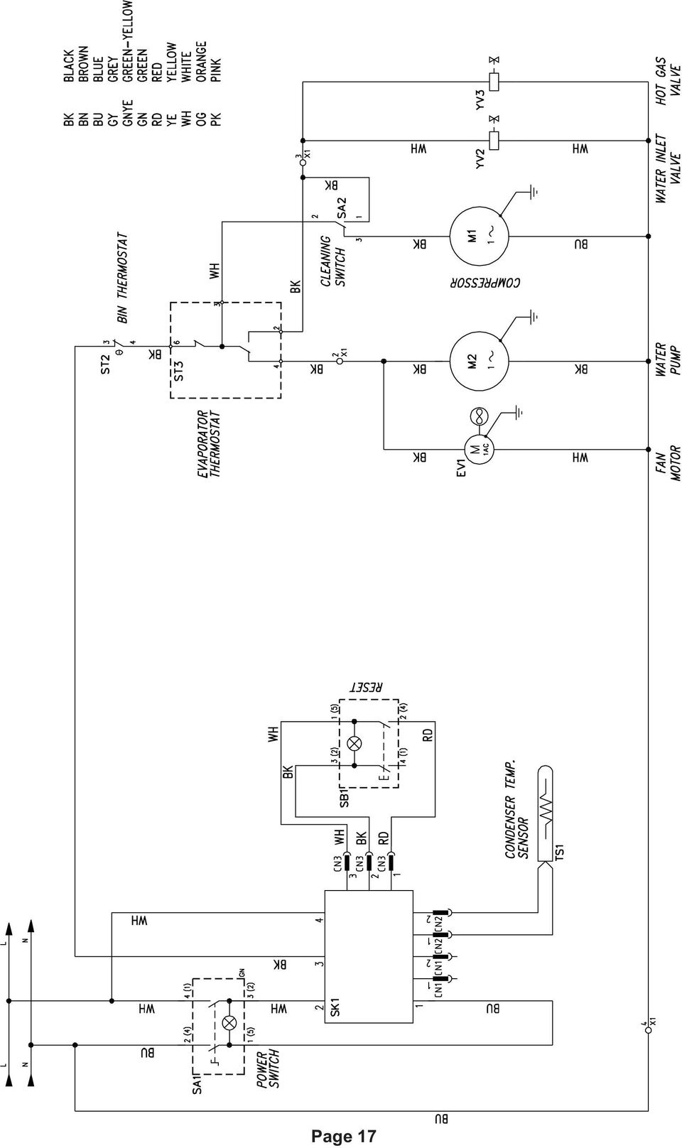
19 Page 17
20 Ice-O-Matic Parts and Labor Domestic & International Limited Warranty Mile High Equipment LLC (the Company ) warrants Ice-O-Matic brand ice machines, ice dispensers, remote condensers, water filters, and ice storage bins to the end customer against defects in material and factory workmanship for the following: Cube ice machines, GEM model compressed ice machines, MFI model flake ice machines and remote condensers. - Thirty-six (36) months parts and labor EF and EMF model flake ice machines - Twenty-four (24) months parts and labor CD model dispensers - Thirty-six (36) months parts and labor Ice storage bins -Twenty-four (24) month parts and labor IOD model dispensers - Twenty-four (24) months parts, Twelve (12) months labor Water filter systems - Twelve (12) months parts and labor (not including filter cartridges) An additional twenty-four (24) month warranty on parts (excluding labor) will be extended to all cube ice machine evaporator plates and compressors, GEM model compressed ice machine compressors, and MFI model flake ice machine compressors from the date of original installation. An additional thirty-six (36) month warranty on parts (excluding labor) will be extended to all EF and EMF model flake ice machine compressors from the date of original installation. The company will replace EXW (Incoterms 2000) the Company plant or, EXW (Incoterms 2000) the Company-authorized distributor, without cost to the Customer, that part of any such machine that becomes defective. In the event that the Warranty Registration Card indicating the installation date has not been returned to Ice-O-Matic, the warranty period will begin on the date of shipment from the Company. Irrespective of the actual installation date, the product will be warranted for a maximum of seventy-two (72) months from date of shipment from the Company. ICE-model cube ice machines which are registered in the Water Filter Extended Warranty Program will receive a total of eighty-four (84) months parts and labor coverage on the evaporator plate from the date of original installation. Water filters must be installed at the time of installation and registered with the Company at that time. Water filter cartridges must be changed every six (6) months and that change reported to the Company to maintain the extended evaporator warranty. No replacement will be made for any part or assembly which (I) has been subject to an alteration or accident; (II) was used in any way which, in the Company s opinion, adversely affects the machine s performance; (III) is from a machine on which the serial number has been altered or removed; or, (IV) uses any replacement part not authorized by the Company. This warranty does not apply to destruction or damage caused by unauthorized service, using other than Ice-O-Matic authorized replacements, risks of transportation, damage resulting from adverse environmental or water conditions, accidents, misuse, abuse, improper drainage, interruption in the electrical or water supply, charges related to the replacement of non-defective parts or components, damage by fire, flood, or acts of God. This warranty is valid only when installation, service, and preventive maintenance are performed by a Company-authorized distributor, a Company-authorized service agency, or a Company Regional Manager. The Company reserves the right to refuse claims made for ice machines or bins used in more than one location. This Limited Warranty does not cover ice bills, normal maintenance, after-install adjustments, and cleaning. Limitation of Warranty This warranty is valid only for products produced and shipped from the Company after January, A product produced or installed before that date shall be covered by the Limited Warranty in effect at the date of its shipment. The liability of the Company for breach of this warranty shall, in any case, be limited to the cost of a new part to replace any part, which proves to be defective. The Company makes no representations or warranties of any character as to acessories or auxiliary equipment not manufactured by the Company. REPAIR OR REPLACEMENT AS PROVIDED UNDER THIS WARRANTY IS THE EXCLUSIVE REMEDY OF THE CUSTOMER. MILE HIGH EQUIPMENT SHALL NOT BE LIABLE FOR ANY INCIDENTAL OR CONSEQUENTIAL DAMAGES FOR BREACH OF ANY EXPRESS OR IMPLIED WARRANTY ON THIS PRODUCT. EXCEPT TO THE EXTENT PROHIBITED BY APPLICABLE LAW, ANY IMPLIED WARRANTY OR MERCHANTABILITY OR FITNESS FOR A PARTICULAR PURPOSE ON THIS PRODUCT IS LIMITED IN DURATION TO THE LENGTH OF THIS WARRANTY. Filing a Claim All claims for reimbursement must be received at the factory within 90 days from date of service to be eligible for credit. All claims outside this time period will be void. The model, the serial number and, if necessary, proof of installation, must be included in the claim. Claims for labor to replace defective parts must be included with the part claim to receive consideration. Payment on claims for labor will be limited to the published labor time allowance hours in effect at the time of repair. The Company may elect to require the return of components to validate a claim. Any defective part returned must be shipped to the Company or the Company-authorized distributor, transportation charges pre-paid, and properly sealed and tagged. The Company does not assume any responsibility for any expenses incurred in the field incidental to the repair of equipment covered by this warranty. The decision of the Company with respect to repair or replacement of a part shall be final. No person is authorized to give any other warranties or to assume any other liability on the Company s behalf unless done in writing by an officer of the Company. GOVERNING LAWhis Limited Warranty shall be governed by the laws of the state of Delaware, U.S.A., excluding their conflicts of law principles. The United Nations Convention on Contracts for the International Sale of Goods is hereby excluded in its entirety from application to this Limited Warranty. Mile High Equipment LLC, East 45 th Avenue, Denver, Colorado (303) January 2007 Page 18
 months parts and labor EF and EMF model flake ice machines - Twenty-four (24) months parts and labor CD model dispensers - Thirty-six (36) months parts and labor Ice storage bins")
21
Name of Equipment Silver King Model SKMCD1P/C1. This equipment chapter is to be inserted in the appropriate section of the Equipment Manual.
 Name of Equipment Silver King Model SKMCD1P/C1 This equipment chapter is to be inserted in the appropriate section of the Equipment Manual. Manufactured exclusively for McDonald s By Silver King Refrigeration,
Installation Manual GEMU090 Series
 Installation Manual GEMU090 Series Ice-O-Matic 11100 East 45th Ave Denver, Colorado 80239 Part Number 9081430-0101 / 17-3371-01 Date t 9/11 Ice-O-Matic Parts and Labor Domestic & International Limited
NewAir AC-10100E / AC-10100H Portable Air Conditioner Owner s Manual PLEASE READ AND SAVE THESE INSTRUCTIONS
 NewAir AC-10100E / AC-10100H Portable Air Conditioner Owner s Manual PLEASE READ AND SAVE THESE INSTRUCTIONS ELECTRICAL SAFETY This appliance is for indoor use only. Always turn off the unit and unplug
Table Z. Troubleshooting Chart for Air Conditioners. Cause
 Troubleshooting Chart for Air Conditioners Type of Unit Complaint Cause With open-type compressor Electric motor will not start Power failure Check circuit for power source Compressor stuck Locate cause
USER MANUAL. Bottom Loading Bottled Water Dispenser SAVE THIS MANUAL FOR FUTURE USE. Model # 900172
 Model # 900172: Page 1 USER MANUAL Bottom Loading Bottled Water Dispenser Model # 900172 TO REDUCE THE RISK OF INJURY AND PROPERTY DAMAGE, USER MUST READ THIS MANUAL BEFORE ASSEMBLING, INSTALLING & OPERATING
CU50 Service Manual Introduction:
 Introduction: This ice machine is the result of Scotsman s decades of experience as an industry leader in the design and manufacture of both commercial and residential ice machines. This manual includes
Portable Air Conditioner. OWNER S MANUAL Read these instructions before use. Model: MF08CESWW. Voltage rating: 115V~60Hz Power rating : 800W
 MODE ALARM Portable Air Conditioner OWNER S MANUAL Read these instructions before use 8 Model: MF08CESWW Voltage rating: 115V~60Hz Power rating : 800W Customer Support : 1-800-474-2147 For product inquiries
DC REFRIGERATORS 12/24 VOLTS INSTALLATION AND OWNER S MANUAL
 DC REFRIGERATORS 12/24 VOLTS INSTALLATION AND OWNER S MANUAL Service Information If service or parts are required, contact the nearest Norcold Service Center. To find an authorized Norcold Service Center
Foodservice Equipment Specialists P.O. Box 880 Saco, ME. / U.S.A. 04072 877-854-8006 * FAX (207) 283-8080
 283-8080") Foodservice Equipment Specialists P.O. Box 880 Saco, ME. / U.S.A. 04072 877-854-8006 * FAX (207) 283-8080 FOR SERVICE ASSISTANCE U.S. AND CANADA CALL: 1-877-854-8006 24 HOURS/DAY 7 DAYS/WEEK TABLE OF CONTENTS
Foodservice Equipment Specialists P.O. Box 880 Saco, ME. / U.S.A. 04072 877-854-8006 * FAX (207) 283-8080 FOR SERVICE ASSISTANCE U.S. AND CANADA CALL: 1-877-854-8006 24 HOURS/DAY 7 DAYS/WEEK TABLE OF CONTENTS
PROAIR Water-Cooled Air Conditioner. CR43WC Model INSTRUCTION MANUAL. Rev. E 2013 Pentair Technical Products P/N 10-1008-167
 PROAIR Water-Cooled Air Conditioner CR43WC Model INSTRUCTION MANUAL Rev. E 2013 Pentair Technical Products P/N 10-1008-167 87976466 TABLE OF CONTENTS HANDLING & TESTING THE AIR CONDITIONER...3 INSTALLATION
Portable Air Conditioner. OWNER S MANUAL Read these instructions before use. Model: MM14CCS. Voltage rating: 115V~60Hz Power rating : 1400W
 Portable Air Conditioner OWNER S MANUAL Read these instructions before use Model: MM14CCS Customer Support : 1-800-474-2147 Voltage rating: 115V~60Hz Power rating : 1400W For product inquiries or support
Portable Air Conditioner. OWNER S MANUAL Read these instructions before use. Model: MN12CES / MN10CESWW
 Portable Air Conditioner OWNER S MANUAL Read these instructions before use 8 Model: MN12CES / MN10CESWW Voltage rating: 120V~60Hz Power rating : 1100W (MN12CES) Power rating : 900W (MN10CESWW) Customer
543-0032-00, 943-0032-00. User s Manual
 543-0032-00, 943-0032-00 User s Manual 1 Comfort Alert Diagnostics Faster Service And Improved Accuracy The Comfort Alert diagnostics module is a breakthrough innovation for troubleshooting heat pump and
NewAir AC-10000E, AC-10000H Portable Air Conditioner Owner s Manual PLEASE READ AND SAVE THESE INSTRUCTIONS
 NewAir AC-10000E, AC-10000H Portable Air Conditioner Owner s Manual PLEASE READ AND SAVE THESE INSTRUCTIONS BEFORE USE GENERAL SAFETY INSTRUCTIONS: ALWAYS OPERATE THE UNIT IN AN UPRIGHT POSITION AND PLACE
Dehumidifier Users manual. For Models: DH45S DH65S
 Dehumidifier Users manual For Models: DH45S DH65S 950-0062-revD Jan. 9 2007 FORWARD The appearance of the units that you purchase might be slightly different from the ones described in the Manual, but
Portable Air Conditioner
 Portable Air Conditioner Owner's Manual Model:3 in 1 12,000 Btu/h Series 3 Please read this owner s manual carefully before operation and retain it for future reference. CONTENTS 1. SUMMARY...1 2. PORTABLE
F20, F40, F60, F85 & FCI20, FCI30, FCI40 FCI60, FCI85 Cube Ice Maker
 F20, F40, F60, F85 & FCI20, FCI30, FCI40 FCI60, FCI85 Cube Ice Maker S e r v i c e M a n u a l Foster Ice Cuber Machine CONTENTS Page 1. General Information and Installation Instructions 2 1.1 Introduction
LOBOY 16 AIR CONDITIONERS
 INSTRUCTION MANUAL FOR: LOBOY 16 AIR CONDITIONERS McLean Midwest Corp. dba: McLean Cooling Technology 11611 Business Park Blvd. N Champlin, MN 55316 Tel: 763-323-8200 Fax: 763-576-3200 www.mcleancoolingtech.com
Portable Air Conditioner. OWNER S MANUAL Read these instructions before use. Model: MM14CHCSCS
 Portable Air Conditioner OWNER S MANUAL Read these instructions before use Model: MM14CHCSCS Voltage rating: 120V~60Hz Power rating : 1400W(Cooling) Power rating : 1350W(Heating) Customer Support : 1-800-474-21477
Instructional & Operating Manual
 Instructional & Operating Manual For CoolFreeze Series Portable Refrigerators/Freezers CF-18, CF-25, CF-35, CF-40, CF-50, CF-80, CF-110 WAECO USA Clinton, CT www.waecousa.com ! Safety indications in the
REFRIGERATED TYPE COMPRESSED AIR DRYERS INSTRUCTION MANUAL. For Sales & Service please contact:
 7610.478.16 8/99 INSTRUCTION MANUAL Models 8005, 8010, 8015 For Sales & Service please contact: CENTRAIR Air Systems & Supplies Phone: 705-722-5747 Fax: 705-722-5458 Email: [email protected] Website: www.centrair.ca
Service/Part Manual. Self-Contained Electronic Ice Maker. 99040401A Version: 2009.4. Scotsman-webshop.nl
 Service/Part Manual Self-Contained Electronic Ice Maker 99040401A Version: 2009.4 - 1 - Content Table of Contents Ice Maker Instruction 2-3 Product Specifications Introduction 4 Unpacking and Inspection
Oil and Coolant Circulating Heating System. Model - OCSM
 Oil and Coolant Circulating Heating System Model - OCSM Installation & Operation Manual 216280-000 REV 2 Identifying Your System The HOTSTART heating system is designed to heat fluids for use in marine
T15 AIR CONDITIONER INSTRUCTION MANUAL FOR: McLean Thermal 11611 Business Park Blvd. N Champlin, MN 55316 Tel: 763-323-8200 Fax: 763-576-3200
 INSTRUCTION MANUAL FOR: T15 AIR CONDITIONER McLean Thermal 11611 Business Park Blvd. N Champlin, MN 55316 Tel: 763-323-8200 Fax: 763-576-3200 www.mcleanthermal.com INSTRUCTION MANUAL TABLE OF CONTENTS
Panel Mounted Air Conditioners by Dantherm, Inc.
 Panel Mounted Air Conditioners by Dantherm, Inc. CS020020A/B with USACG-6 Control PRODUCT INFORMATION MANUAL AC-2 CS020020 USACG-6 Manual Rev H Page 1 of 17 Dantherm, Inc. 110 Corporate Drive, Suite K
Hoshizaki America, Inc.
 Hoshizaki America, Inc. Stackable Crescent Cuber Models KM-1301SAH/3, SWH/3, SRH/3 KM-1400SWH-M, SWH3-M KM-1601SAH/3, SWH/3, SRH/3 KM-1900SAH/3, SWH/3, SRH/3 KM-2100SWH3, SRH3 KM-2500SWH3, SRH3 KMH-2000SWH/3,
Instruction Manual. Image of SP-3015 & SP-3815. Important Safeguards. Automatic Dispensing Hot Water Pot with Reboil Function
 Important Safeguards READ ALL INSTRUCTIONS BEFORE USE. Instruction Manual Automatic Dispensing Hot Water Pot with Reboil Function Image of SP-3015 & SP-3815 SP-3015: 3.0L SP-3815: 3.8L SP-3017: 3.0L (Stainless
Line to Refrigerator Ice/Water Dispenser
 Standard 18 Line to Refrigerator Ice/Water Dispenser Pump Module Bottled Water How The System Works The FLOJET Bottled Water Dispensing System was designed to pump water from a commercially available 5-gallon
Table V. Troubleshooting Checklist for Refrigeration Systems. Air or non-condensable gas in system. Inlet water warm.
 Table V Troubleshooting Checklist for Refrigeration Systems TROUBLE POSSIBLE CAUSE CORRECTIVE MEASURE High condensing pressure. Low condensing pressure. Air or non-condensable gas in system. Inlet water
USER S MANUAL HSC-24A
 AIRREX AIR CONDITIONER USER S MANUAL HSC-24A Thank you for purchasing an AIRREX AIR CONDITIONER. BEFORE operation please read this user s manual carefully. Keep this manual readily available. It is ESSENTIAL
WH/WIH/WIHD/WIHD&M/WIHL AND WIH 17-67 SERIES
 WH/WIH/WIHD/WIHD&M/WIHL AND WIH 17-67 SERIES Service and Installation Manual Please read this manual completely before attempting to install or operate this equipment! Notify carrier of damage! Inspect
Geyser-R Heat pump water heater Installation manual
 Geyser-R Heat pump water heater Installation manual 1 Version 2.9 SAFETY INFORMATION Please read carefully to prevent serious accidents or injury. The Geyser-R Heat Pump Water Heater must be installed
Home Owners Guide HR SERIES HEAT RECOVERY VENTILATOR (HRV) Models HR100V, HR160H & HR220H RESIDENTIAL USE ONLY HR160H & HR220H
 Models HR100V, HR160H & HR220H RESIDENTIAL USE ONLY HR160H & HR220H") HR SERIES HEAT RECOVERY VENTILATOR (HRV) Home Owners Guide Models HR100V, HR160H & HR220H RESIDENTIAL USE ONLY HR100V HR160H & HR220H READ AND SAVE THIS GUIDE PP0924 09/2013 ABOUT S&P S&P is the world's
HR SERIES HEAT RECOVERY VENTILATOR (HRV) Home Owners Guide Models HR100V, HR160H & HR220H RESIDENTIAL USE ONLY HR100V HR160H & HR220H READ AND SAVE THIS GUIDE PP0924 09/2013 ABOUT S&P S&P is the world's
Use & Care Manual. 15 W. Undercounter/Freestanding Ice Machine. Viking Range, LLC 111 Front Street Greenwood, Mississippi 38930 USA (662) 455-1200
 455-1200") Use & Care Manual Viking Range, LLC 111 Front Street Greenwood, Mississippi 38930 USA (662) 455-1200 For product information, call 1-888-(845-4641) or visit our web site at vikingrange.com in the US or
Use & Care Manual Viking Range, LLC 111 Front Street Greenwood, Mississippi 38930 USA (662) 455-1200 For product information, call 1-888-(845-4641) or visit our web site at vikingrange.com in the US or
Hot, Warm and Cold Mineral Water Cooler [Models Cool18, Cool25, Cool36, Cool50, Cool75, Cool100]
![Hot, Warm and Cold Mineral Water Cooler [Models Cool18, Cool25, Cool36, Cool50, Cool75, Cool100]](/thumbs/26/7741864.jpg "Hot, Warm and Cold Mineral Water Cooler [Models Cool18, Cool25, Cool36, Cool50, Cool75, Cool100]") Hot, Warm and Cold Mineral Water Cooler [Models Cool18, Cool25, Cool36, Cool50, Cool75, Cool100] PLEASE READ BEFORE INSTALLATION TO PREVENT DAMAGE TO THE COOLER HOT WATER TANK STEAM EXAUST VENT (CAUTION!)
Hot, Warm and Cold Mineral Water Cooler [Models Cool18, Cool25, Cool36, Cool50, Cool75, Cool100] PLEASE READ BEFORE INSTALLATION TO PREVENT DAMAGE TO THE COOLER HOT WATER TANK STEAM EXAUST VENT (CAUTION!)
CARING FOR YOUR WATER HEATER
 http://waterheatertimer.org/troubleshoot-rheem-tankless-water-heater.html Water Heater Inspections CARING FOR YOUR WATER HEATER Venting System (Direct Vent Only) The venting system should be inspected
Service manual. Website: www.andico.com.au CAUTION - BEFORE SERVICING THE UNIT, READ THE SAFETY - PRECAUTIONS IN THIS MANUAL.
 Website: www.andico.com.au Service manual CAUTION - BEFORE SERVICING THE UNIT, READ THE SAFETY - PRECAUTIONS IN THIS MANUAL. - ONLY FOR AUTHORISED SERVICE PERSONNEL. MODELS: MPK1-09CR-QB8 MPK1-12ER-QB6
Heat Pump Water Heater IOM Manual
 Heat Pump Water Heater IOM Manual Installation Operation & Maintenance This manual is intended as an aid to qualified service personnel for proper installation, operation and maintenance of the heat pump
Service & Parts Manual
 Service & Parts Manual Portable Air Conditioner Models P09B and P2B ( Serial Number Beginning with an "A") Models P09B-A and P2B-A Portable Air conditioner-200 Svc Parts (4-200) Service Points and Flow
WALL MOUNTED SPLIT TYPE AIR CONDITIONER
 WALL MOUNTED SPLIT TYPE AIR CONDITIONER MANUAL 8 OM-G12-ACSON CONTENTS - Operating Guide page 1 - G12 Remote Controller Indication page 2 - Indicator Lights page 4 - Installation of Aroma page 5 - Auto
SECTION ONE INSTALLATION CONSIDERATIONS
 SECTION ONE INSTALLATION CONSIDERATIONS LOCATION The ice maker may be closed in on the top, rear and two sides. The front MUST BE unobstructed for proper air circulation and operation. Installation should
Model 800 Residential Steam Humidifier Owner s Manual. Includes Safety & Operating Instructions and Warranty Information
 Steam Humidifier Model 800 Residential Steam Humidifier Owner s Manual Includes Safety & Operating Instructions and Warranty Information READ AND SAVE THESE INSTRUCTIONS TABLE OF CONTENTS Safety Cautions...
Seaward Products OWNER S MANUAL WATER HEATERS. Serial Number:
 Seaward Products WATER HEATERS OWNER S MANUAL Serial Number: IMPORTANT SAFETY INSTRUCTIONS WARNING When using electrical appliances, basic safety precautions to reduce the risk of fire, electrical shock,
User's Manual for Residential Ice Machine Model DCE33
 User's Manual for Residential Ice Machine Model DCE33 INTRODUCTION The Scotsman DCE33 is a restaurant type ice machine designed for home use. It produces the same high quality ice as large Scotsman commercial
SERVICE MANUAL. Room Air Conditioner Multi Split Wall-Mounted Type Indoor. FSAI-Pro-91AE2 FSAI-Pro-121AE2 FSAIF-Pro-181AE2
 SERVICE MANUAL Room Air Conditioner Multi Split Wall-Mounted Type Indoor FSAI-Pro-91AE2 FSAI-Pro-121AE2 FSAIF-Pro-181AE2 NOTE: Before servicing the unit, please read this at first. Always contact with
Miami Heat Pump HP Series Installation Guide
 CAUTION- THIS UNIT IS FOR INDOOR USE ONLY!! WARNING BEFORE ANY INSTALLATION OR MAINTANCE IS STARTED PLEASE READ COMPLETE INSTLLATION GUIDE. INSTALLATION START-UP AND SERVICE INSTRUCTION- The HP Water Source
ICE AIR. Console Water Source Heat Pump (WSHP) OPERATING & MAINTENANCE MANUAL. Wo r l d C l a s s C o m f o r t. www.ice-air.com
 OPERATING & MAINTENANCE MANUAL. Wo r l d C l a s s C o m f o r t. www.ice-air.com") 80 Hartford Avenue Mount Vernon New York 10553 Tel: 914-668-4700 EXT. 203 Fax: 914-668-5643 www.ice-air.com Wo r l d C l a s s C o m f o r t Console Water Source Heat Pump (WSHP) OPERATING & MAINTENANCE
80 Hartford Avenue Mount Vernon New York 10553 Tel: 914-668-4700 EXT. 203 Fax: 914-668-5643 www.ice-air.com Wo r l d C l a s s C o m f o r t Console Water Source Heat Pump (WSHP) OPERATING & MAINTENANCE
Single Zone LCD Thermostat Operating Instructions
 Fan Cool Furnace *Heat Pump or Heat Strip On/Off F Single Zone LCD Thermostat Operating Instructions MODEL 3313192.XXX Cool/Furnace 3313193.XXX Cool/Furnace/Heat Pump 3313194.XXX Cool/Furnace/Heat Strip
Electric Water Heater
 Electric Water Heater Operation and Installation Manual (LIMITED WARRANTY AND TANK REPLACEMENT POLICY) The following information should be noted at time of installation and retained for future reference.
USE &CARE GUIDE. Remote Faucet Pump System. See Important Safeguards on page 2
 Remote Faucet Pump System USE &CARE GUIDE See Important Safeguards on page 2 An exclamation point within an equilateral triangle is intended to alert user to the presence of important operating and maintenance
Indirect-Fired Storage Water Heater Models WH-30 through WH-80 INSTALLATION AND OPERATING INSTRUCTIONS
 Indirect-Fired Storage Water Heater Models WH-30 through WH-80 INSTALLATION AND OPERATING INSTRUCTIONS Contents Page Ratings and Specifications..................... 2 Installation Requirements......................
MASTER. Installation and Operation Manual. Water Conditioning Corp. MCA Time Clock Series Residential Softeners. February 2011 Version
 MASTER Water Conditioning Corp. Installation and Operation Manual MCA Time Clock Series Residential Softeners February 2011 Version Table of Contents Page No. Topic Description 1 Model # and Packaging
HEAT PUMP FREQUENTLY ASKED QUESTIONS HEAT PUMP OUTDOOR UNIT ICED-UP DURING COLD WEATHER:
 HEAT PUMP FREQUENTLY ASKED QUESTIONS HEAT PUMP OUTDOOR UNIT ICED-UP DURING COLD WEATHER: It is normal for a heat pump to have a build up of white frost on the outside coil during cold damp weather. The
Model: Model: Description: Voltage: Amps: 15.3. Ice Type: Unit Weight:
 Model MIM452 Project Name: Location: Item: Qty: Modular Ice Maker FEATURE LIST MIM452 Description: Modular Ice Maker Voltage: 120V/60Hz/1Ph, 220V/50Hz/1Ph Amps: 15.3 Model MIM452 (Shown on bin, model MIB400,
INSTALLER S & OWNER S MANUAL
 INSTALLER S & OWNER S MANUAL HVAC INSTALLER: PLEASE LEAVE MANUAL FOR HOMEOWNER DEH 3000 DEH 3000 Part No. 4028539 Dehumidifier & Ventilation System Controller P.O. Box 8680 Madison, WI 53708 TOLL-FREE
T-Series Air Conditioner T62 Model
 INSTRUCTION MANUAL T-Series Air Conditioner T62 Model Protecting Electronics. Exceeding Expectations. McLean Cooling Technology 11611 Business Park Blvd N Champlin, MN 55316 USA Tel 763-323-8200 Fax 763-576-3200
USER MANUAL WARNING! CONTENTS MODEL 1 SPECIFICATIONS READ ALL INSTRUCTIONS BEFORE PROCEEDING. Non-Programmable Single Stage Heat/Cool Thermostat
 Builder MODEL 1010 Series Non-Programmable Single Stage Heat/Cool Thermostat USER MANUAL Compatible with low voltage single stage gas, oil or electric heating or cooling systems, including single stage
Nexus FS Point of Use Installation Guide
 Nexus FS Point of Use Installation Guide Nexus FS POU Install Guide:12152011:rev-12152011 Technical Specifications Dimensions: Height: 43.5 Width: 11.65 Depth: 15 Weight: 34.39 LBS Electrical Specs: Voltage:
Vertical Display and Storage B1350-2. SKOPE Gen2: Three Door Chiller
 Vertical Display and Storage User Manual MAN1227 Rev. 3.0 March 2008 edition CONTACT ADDRESSES Designed and Manufactured by New Zealand SKOPE INDUSTRIES LIMITED PO Box 1091, Christchurch New Zealand Freephone:
Electric Fryers Instruction Manual Models: 8047D, 8048D, 8049D, 8050D, 8051D 8066, 8068, 8068FL, 8073, 8073BF and 8075
 Part No. 89047 Electric Fryers Instruction Manual Models: 8047D, 8048D, 8049D, 8050D, 8051D 8066, 8068, 8068FL, 8073, 8073BF and 8075 Cincinnati, OH 45241-4807 USA ELECTRIC FRYER SAFETY PRECAUTIONS Installation
Please read this owner s Manual carefully before operating the unit. - Cooling - Heating - Dehumidifying - Fan
 Please read this owner s Manual carefully before operating the unit. - Cooling - Heating - Dehumidifying - Fan TABLE OF CONTENTS INTRODUCTION 2 IMPORTANT SAFEGUARDS...2 PACKAGE CONTAINS..2 NAMES OF PARTS.3
PC1131 Electric Air Compressor
 Senco Products Inc. 8485 Broadwell Road Cincinnati, Ohio 45244 PC1131 Electric Air Compressor Operating Instructions 2006 by Senco Products, Inc. Warnings for the safe use of this tool are included in
Installation and Troubleshooting Instructions for Electric Tankless Residential Water Heaters.
 Model Number: Serial Number: Information Manual Installation and Troubleshooting Instructions for Electric Tankless Residential Water Heaters. ATTENTION: IF YOU ARE NOT A LICENSED PLUMBER OR A LICENSED
T-SERIES Air Conditioner. T29 Model INSTRUCTION MANUAL. Rev. F 2016 Pentair Equipment Protection P/N 89104464
 T-SERIES Air Conditioner T29 Model INSTRUCTION MANUAL Rev. F 2016 Pentair Equipment Protection P/N 89104464 89104464 TABLE OF CONTENTS RECEIVING THE AIR CONDITIONER...3 HANDLING AND TESTING THE AIR CONDITIONER...3
PC1130 Electric Air Compressor
 Senco Products Inc. 8485 Broadwell Road Cincinnati, Ohio 45244 PC1130 Electric Air Compressor Operating Instructions 2006 by Senco Products, Inc. Warnings for the safe use of this tool are included in
MBA-MM-1040/10/13/1665 MULTI MEDIA FILTERS
 MASTER Water Conditioning Corp. www.masterwater.com Installation and Operation Manual MBA-MM-1040/10/13/1665 MULTI MEDIA FILTERS with the 263/742 Logix Control Valve June 2010 Table of Contents Page No.
INSTANT HOT WATER RECIRCULATING SYSTEM
 INSTANT HOT WATER RECIRCULATING SYSTEM INSTALLATION AND OPERATING INSTRUCTIONS Save manual for future reference MODEL 500800 Warning Please read carefully before proceeding with installation. Your failure
Advantium 2 Plus Alarm
 ADI 9510-B Advantium 2 Plus Alarm INSTALLATION AND OPERATING INSTRUCTIONS Carefully Read These Instructions Before Operating Carefully Read These Controls Corporation of America 1501 Harpers Road Virginia
HVAC-02, Air Conditioning Troubleshooting and Repair
 HVAC-02, Air Conditioning Troubleshooting and Introduction Since I'm constantly receiving questions on 944 air conditioning systems, I figured it's time to come up with come helpful troubleshooting tips.
10 YEAR WARRANTY REGISTRATION PROCEDURES. Please see product warranty section in back of book for registration procedures
 10 YEAR WARRANTY REGISTRATION PROCEDURES Please see product warranty section in back of book for registration procedures Carrier Systems are eligible for 10 YEAR Warranty Coverage when registered! Important
Compressor Service & Maintenance Manual
 Compressor Service & Maintenance Manual C Series COMPRESSOR (D)C1103 (D)C1203 (D)C2106 (D)C2206 (D)C3210 Copyright 2006 DCI. All Rights Reserved. 92311, Rev. C, 08/13 1 C1000 Series Service & Maintenance
OWNER S Manual PRINTED IN CANADA 10/2009
 OWNER S Manual PRINTED IN CANADA 10/2009 Table of contents Introduction 2 General Safety Instructions 4 Installation Instructions Location 6 Water piping 7 Electrical 7 Bonding 8 Bonding and plumbing
Bottom Loading Water Dispenser
 Bottom Loading Water Dispenser Model # 601000 TO REDUCE THE RISK OF INJURY AND PROPERTY DAMAGE, USER MUST READ THIS MANUAL BEFORE ASSEMBLING, INSTALLING & OPERATING DISPENSER. SAVE THIS MANUAL FOR FUTURE
Air Conditioner Water Heater - A Product of HotSpot Energy LLC
 Air Conditioner Water Heater - A Product of HotSpot Energy LLC PLEASE READ THIS BEFORE YOU INSTALL THE UNIT 1. This air conditioner must be installed and/or repaired by a qualified technician. If you perform
WMSLW / WMBLWH Series Hydronic Upflow/Horizontal Left or Right, Heating and Cooling Air Handler
 WMSLW / WMBLWH Series Hydronic Upflow/Horizontal Left or Right, Heating and Cooling Air Handler Installation Operation Maintenance The WMSLW/WMBLW series is designed for installation in a closet, utility
FOR THE FOLLOWING MODELS: EE-8075W EE-8075O EE-8075R EE-8075BK
 FIREPLACE HEATER FOR THE FOLLOWING MODELS: EE-8075W EE-8075O EE-8075R EE-8075BK If you have any questions about the operation of your fireplace heater, please contact Crane Customer Care. Toll Free: 888-599-0992
TABLE OF CONTENTS UNIT FEATURES OPERATING INSTRUCTIONS. 230V 20 Amp. 120V 15 Amp Figure 1. LCDI Power Cord Figure 2
 THROUGH THE WALL ROOM AIR CONDITIONER WITH OPTIONAL ELECTRIC HEAT INSTALLATION INSTRUCTIONS RECOGNIZE THIS SYMBOL AS A SAFETY PRECAUTION. ATTENTION INSTALLING PERSONNEL As a professional installer you
USER INSTRUCTIONS FOR 10 LITRE PORTABLE DEHUMIDIFIER MODEL NO. DHMD102
 USER INSTRUCTIONS FOR 10 LITRE PORTABLE DEHUMIDIFIER MODEL NO. DHMD102 THANK YOU FOR CHOOSING YOUR NEW DEHUMIDIFIER. BEFORE USING THE UNIT READ THESE INSTRUCTIONS FULLY AND RETAIN THEM FOR FUTURE REFERENCE
Troubleshooting Guide for Dispenser Model #900172
 Troubleshooting Guide for Dispenser Model #900172 Q. The cold water is room temperature. A. There is a cold water thermostat control mounted to the back of the majority of our appliances. Simply unplug
Taurus Series YORK Window Air Conditioners
 Taurus Series YORK Window Air Conditioners IOM IOWRCAG50220711A1 Warning 1. Before using the Air conditioner please read the instructions carefully. They contain important advise about the installation,
Service Guide 12/27/03 TESTING, SERVICE & REPAIR GUIDE (For SH Space Heating Models & RA Water Heating Models)
") TESTING, SERVICE & REPAIR GUIDE (For SH Space Heating Models & RA Water Heating Models) WARNING - HIGH VOLTAGE AC electrical circuits are connected to this heater. Do not attempt any service work on the
TESTING, SERVICE & REPAIR GUIDE (For SH Space Heating Models & RA Water Heating Models) WARNING - HIGH VOLTAGE AC electrical circuits are connected to this heater. Do not attempt any service work on the
WARNING: FAILURE TO FOLLOW THESE RULES MAY RESULT IN SERIOUS PERSONAL INJURY CAUTION: INSTALLATION LOCATION:
 Revision Level: 01 Revision Date: 07/07/2011 Please read all instructions carefully to help ensure a correct and SAFE installation of your Second Wind Ultraviolet Germicidal Air Purifier. Failure to do
INSTALLATION INSTRUCTIONS Fan Coil Replacement Coil Kit EBX & EBXX
 Fan Coil Replacement Coil Kit EBX & EBXX These instructions must be read and understood completely before attempting installation. These instructions covers the installation of replacement coil kit into
Ceiling Mount Air Handler Manual
 www.surna.com 303.993.5271 Ceiling Mount Air Handler Manual Models: CMAH12, CMAH18, CMAH24, CMAH30, CMAH36, CMAH48, CMAH60 Revised: September 2014 Table of Contents Warranty Information 4 Limited Warranty
14. Troubleshooting Guide
 14. Guide 14.1 Refrigeration Cycle System In order to diagnose malfunctions, ensure the air conditioner is free from electrical problems before inspecting the refrigeration cycle. Such problems include
Refrigerant Charging Unit ICOGD. 020AH1000 Operating Manual. FR.8.2.4-09 İ-COLD 12.03.2014 Rev. 00
 E Refrigerant Charging Unit ICOGD 020AH1000 Operating Manual FR.8.2.4-09 İ-COLD 12.03.2014 Rev. 00 Contents Technical Specifications... 20 Safety... 21 A/C System... 22 Components... 23 Control Panel...
CONTENTS 1. IMPORTANT NOTICE 2 2. TECHNICAL SPECIFICATION 3 3. OPERATION DETAILS 4 4. WIRING DIAGRAM 11 5. EXPLOSION VIEW 12 6.
 TCL WALL MOUNTED SPLIT-TYPE AIR CONDITIONERS SERVICE MANUAL No.TE051220 Models TAC-09CHSA/GI TAC-12CHSA/GI CONTENTS 1. IMPORTANT NOTICE 2 2. TECHNICAL SPECIFICATION 3 3. OPERATION DETAILS 4 4. WIRING DIAGRAM
T-SERIES Air Conditioners. T70, 3 Ton and 5 Ton Models INSTRUCTION MANUAL. Rev. H 2013 Pentair Equipment Protection P/N 10-1008-177
 T-SERIES Air Conditioners T70, 3 Ton and 5 Ton Models INSTRUCTION MANUAL Rev. H 2013 Pentair Equipment Protection P/N 10-1008-177 88043249 TABLE OF CONTENTS RECEIVING THE AIR CONDITIONER...3 HANDLING AND
BASYS INSTALLATION INSTRUCTIONS FOR ELECTRONIC CAPACITANCE SENSING LAVATORY FAUCETS EFX-3XX Pedestal, Sensor Activated Lavatory Faucets
 BASYS INSTALLATION INSTRUCTIONS FOR ELECTRONIC CAPACITANCE SENSING LAVATORY FAUCETS EFX-3XX Pedestal, Sensor Activated Lavatory Faucets Any Application. Any Environment. Code No: 0816407 Rev. 4 (07/12)
MAC FAUCETS. Owner s Manual. Models: FA444
 MAC FAUCETS Owner s Manual Models: FA444 Installation procedure: 1. Take a moment to view drawings and read special Installation note on page 3 of this manual before proceeding with installation. Connect
SECTION 23 81 03 - PACKAGED ROOFTOP AIR CONDITIONING UNITS NON-CUSTOM
 SECTION 23 81 03 - PACKAGED ROOFTOP AIR CONDITIONING UNITS NON-CUSTOM PART 1 - GENERAL 1.1 SUMMARY A. Section Includes: 1. Packaged rooftop air conditioning unit (5 tons and smaller). 2. Roof curb. 1.2
WINDOW ROOM AIR CONDITIONER
 WINDOW ROOM AIR CONDITIONER Installation and Operation Manual Electromechanical Remote Control CAPACITIES 220V - 60 HZ. 12,000; 18,000; 24000 BTU/HR 220V-240V - 50 HZ. 12,000; 18,000; 24000 BTU/HR Please
T-Series Air Conditioner
 INSTRUCTION MANUAL T-Series Air Conditioner T15 Protecting Electronics. Exceeding Expectations. Pentair Technical Products 2100 Hoffman Way Anoka, MN 55303 +1-763-323-8200 +1-763-576-3200 www.mcleancoolingtech.com
AIR CONDITIONER & HEAT PUMP DIGITAL CONTROL FOR DUCTED SYSTEM INSTALLATION AND OPERATING INSTRUCTIONS
 AIR CONDITIONER & HEAT PUMP DIGITAL CONTROL FOR DUCTED SYSTEM INSTALLATION AND OPERATING INSTRUCTIONS FOR AC135, AC150, AC135HP, AC150HP, ACRG12, ACTH12 RECORD THIS UNIT INFORMATION FOR FUTURE REFERENCE:
T-SERIES Air Conditioner. T53 Model INSTRUCTION MANUAL. Rev. F 2013 Pentair Equipment Protection P/N 10-1008-224
 T-SERIES Air Conditioner T53 Model INSTRUCTION MANUAL Rev. F 2013 Pentair Equipment Protection P/N 10-1008-224 88004712 TABLE OF CONTENTS RECEIVING THE AIR CONDITIONER...3 HANDLING AND TESTING THE AIR
Roof Top Air Conditioner INSTALLATION AND OPERATING INSTRUCTIONS
 Roof Top Air Conditioner INSTALLATION AND OPERATING INSTRUCTIONS Ducted System RECORD THIS UNIT INFORMATION FOR FUTURE REFERENCE: Model Number: Serial Number: Date Purchased: This manual must be read and
RI-215A Operator s Manual. Part Number: 71-0045RK Revision 0 Released: 10/3/05
 RI-215A Operator s Manual Part Number: 71-0045RK Revision 0 Released: 10/3/05 Warranty RKI Instruments, Inc., warrants gas alarm equipment sold by us to be free from defects in materials and workmanship,
ACW200C / ACW200CH. Innovative AutoDrain Technology. Owner s Manual Portable Air Conditioner with Heat
 Owner s Manual Portable Air Conditioner with Heat ACW200C / ACW200CH It is important that you read these instructions before using your new purchase and we strongly recommend that you keep them in a safe
Nest Learning Thermostat Installation Guide. Installation step-by-step
 Nest Learning Thermostat Installation Guide Installation step-by-step Contents Compatibility. 3 In the box. 4 Before you start. 5 Choose an installation method. 6 Replacing an existing wired thermostat.
NME650 & FME800 INTRODUCTION. Table of Contents
 INTRODUCTION To the owner or user: The service manual you are reading is intended to provide you, and the maintenance or service technician, with the information needed to install, start up, clean, maintain,