Evaluates: EV Kits Requiring SPI/ Parallel to USB Interface. INTF3000 Interface Board. General Description. Quick Start. Benefits and Features
|
|
|
- Britton Horn
- 9 years ago
- Views:
Transcription
1 INTF3000 Interface Board Evaluates: EV Kits Requiring SPI/ Parallel to USB Interface General Description The INTF3000 interface board is designed to facilitate the interfacing of Maxim s evaluation kit (EV) boards to any personal computer (PC) through the USB port. There are three different connectors on the INTF3000 interface board available to communicate with the EV board: INTF2300, INTF2400, and DB25 (LPT) parallel connector. The INTF2400 connector is intended for new designs, while the INTF2300, INTF2400, and DB25 parallel connector can support legacy EV boards that are already configured for one of these types of interfaces. It must be noted that legacy EV boards that were designed to communicate with the PC through DB25 parallel port must also have an updated control software which supports the INTF3000 interface board. All three connectors on INTF3000 interface board support logic levels from 2V to 5V. The INTF3000 requires no special driver installations on the host PC. The board connects to the PC with a standard USB cable. Benefits and Features Parallel Port-to-USB Interface Serial port interface (SPI) to USB Interface Supports Wide Voltage Range: 2V 5V INTF2400 Connector Compatible with Old INTF2400 LPT Port Boards Addressing Enables the Use of up to Four Boards on a Single PC Ordering Information appears at end of data sheet. Quick Start Required Equipment This section lists the recommended equipment to verify the operation of INTF ) INTF3000 interface board 2) PC equipped with Microsoft Windows XP, Windows 7, Windows 8 OS and a USB port 3) USB-A male to USB-B male cable 4) Optional: ribbon cable 5) Optional: DC supply capable of delivering 2.0V to 5.0V and 10mA current Procedure The interface board is fully assembled and tested. Follow the steps below to verify board operation: 1) Connect the INTF3000 to the PC using a USB-A cable to USB-B male cable. 2) Connect to the EV board to the INTF3000 using either DB25 parallel port connector directly or through ribbon cable connected between INTF2400/INTF2300 connector. This depends on what type of connector is present on the EV kit. 3) Connect JU1 in V BUS position to drive everything from 5V from USB. 4) Alternatively, connect JU1 in V DEV position to bias the drivers from EV board V DEV pin, if V CC is routed to V DEV. 5) If JU1 is removed, an external supply (V CC ) must be connected to the test point: V PULL ; Rev 0; 11/15

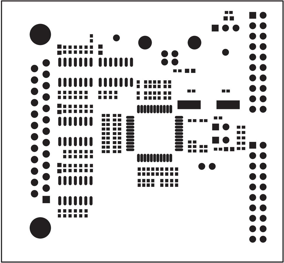
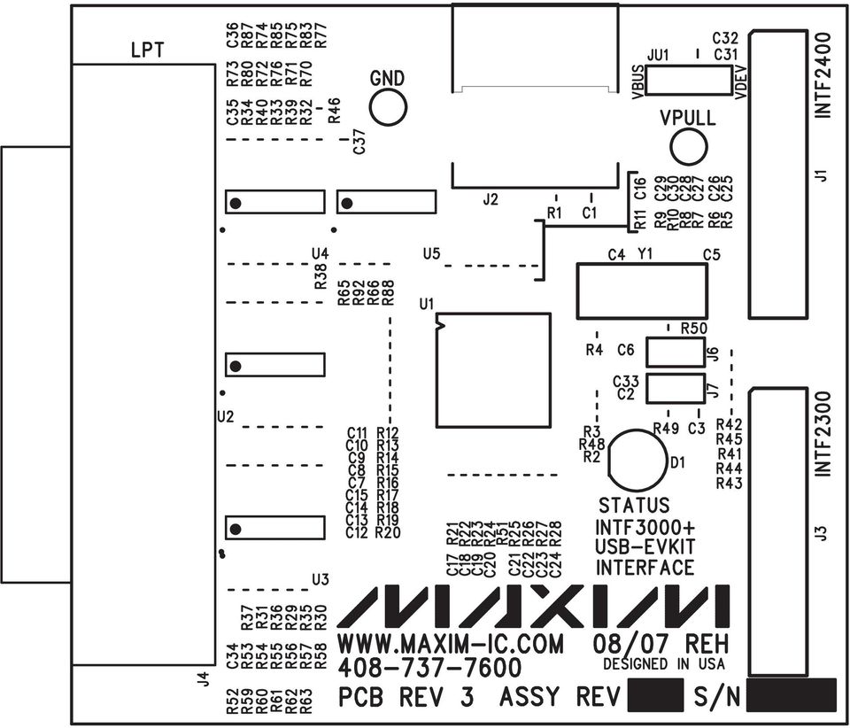
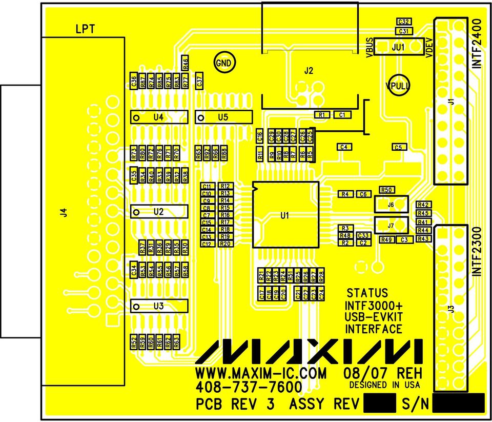
2 INTF3000 Interface Board Evaluates: EV Kits Requiring SPI/Parallel to USB Interface Detailed Description of Hardware This section describes the hardware of the INTF3000 board, explains how the jumpers and connectors should be used by highlighting the input and output signals, and where they are routed to on each of the three connectors. Figure 1 shows the location of these jumpers and connectors. Figure 1. INTF3000 Board Maxim Integrated 2

3 INTF3000 Interface Board Evaluates: EV Kits Requiring SPI/Parallel to USB Interface Input Port Signals There is one port (port D) on the USB controller (U1) dedicated to inputs. There are seven possible input port pins on this port and each interface connector has a different number of these pins available. Table 1, Table 2, and Table 3 show the available input pins on each connector. The inputs are read by the USB controller, with the state returned to the PC. These input signals can be used to determine the state of pins on the DUT or EV board. The logic level of the input buffers is determined by V PULL ; it should always be set to the V CC of the EV board. Table 1. Input Pins on INTF2400 INTF2400 PIN Table 2. Input Pins on INTF2300 INTF2300 PIN 1* 2 3* 4 *Must be enabled with jumper on the INTF3000 board, otherwise, these pins are ground. Table 3. Input Pins on LPT Connector LPT PIN U1 INPUT PORT PIN RD3L RD2L RD1L RD0L U1 INPUT PORT PIN RD4L RD6L RD5L RD7L U1 INPUT PORT PIN RD0L RD1L RD2L RD3L RD4L Output Port Signals The USB controller (U1) has two output ports (RA and RB) connected to the interface connectors. There are a maximum of twelve output port signals available on the INTF3000 board. Each of the three connectors has a different number of these signals available. Table 4, Table 5, and Table 6 show the available output signals on each connector. The output buffers (U2 U5) can either drive each output pin low or let it float. A pullup resistor on each line pulls the output to V PULL, setting it to high level when floating. V PULL can be supplied by different sources depending on jumper JU1 setting and this allows for DUT logic levels from 2V to 5V. Table 4. Output Pins for INTF2400 INTF2400 PIN Table 5. Output Pins for INTF2300 INTF2300 PIN U1 OUTPUT PORT PIN RB0L RB1L RB2L RB3L RB4L RB5L RB6L RB7L RA2L RA0L RA3L RA1L U1 OUTPUT PORT PIN RB6L RB5L RB4L RB3L RB2L RB1L RB0L Maxim Integrated 3

4 INTF3000 Interface Board Evaluates: EV Kits Requiring SPI/Parallel to USB Interface The outputs can be a serial clock, serial data, serial chip select, or just a control pin to turn on/off functions on the DUT. Serial signals are not limited to a specific pin; the software, not the hardware, defines the function of each output pin. Jumpers JU1 JU1 configures the pullup resistors for the output drivers (U2 and U3). Each output RA0 RA5 and RB0 RB7 has an open-drain driver. These drivers are used to level translate the 5V logic of the USB controller to the lower voltage logic levels of the DUT EV board. If JU1 is in the V BUS position, the inputs and outputs of the drivers are compatible with 5V logic only. If JU1 is in the V DEV position, the drivers get their bias from the logic supply voltage of the DUT EV board through Pin 1 of INTF2400 or Pin 12 of INTF2300 connector. It should be noted that the DUT EV board must have the logic supply voltage routed to these pins. If JU1 is removed, an external V CC can be connected to the test point (V PULL ). This configuration must be used for low V CC boards that do not have their V CC routed to V DEV. Some legacy EV boards that have the DB25 connector must use this configuration since the DB25 connector does not have a V DEV pin. JU6, JU7 JU6 and JU7 set the address of the INTF3000 board. There are four possible addresses so that up to four different INTF3000 boards may be used on one PC. Table 7 shows these four addresses and the associated jumper positions. The software used must be set to the same address as the jumper configuration. Table 7. INTF3000 Possible Addresses ADDRESS JU6 JU7 9123* Removed Removed 9124 Removed Installed 9125 Installed Removed 9126 Installed Installed * This is the default address for most EV boards. LED LED D1 serves two purposes: 1) D1 will blink once when the INTF3000 is first connected. This shows that the processor has powered-up properly. 2) D1 will toggle on and off for every command received from the PC. This shows activity. Table 6. Output Pins for LPT Connector LPT PIN U1 OUTPUT PORT PIN RB0L RB1L RB2L RB3L RB4L RB5L RB6L RB7L RA0L RA1L RA2L RA3L Maxim Integrated 4

5 INTF3000 Interface Board Evaluates: EV Kits Requiring SPI/Parallel to USB Interface Interface Connectors Parallel (LPT) Connector The parallel port connector is a DB25 connector wired to have the same pinout as a parallel port. This connector can be used to connect to legacy EV boards, which use the DB25 connector as shown in Figure 3. Table 8 shows the port pins associated with this connector. Table 8. LPT Connector Port Pins DB25 PIN LABEL FUNCTION 1 RB0L Output Pin 2 RB1L Output Pin 3 RB2L Output Pin 4 RB3L Output Pin 5 RB4L Output Pin 6 RB5L Output Pin 7 RB6L Output Pin 8 RB7L Output Pin 9 RA0L Output Pin 10 RD0L Input Pin 11 RD1L Input Pin 12 RD2L Input Pin 13 RD3L Input Pin For legacy boards, if the DUT V CC < 3.3V, remove JU1 and connect test point V PULL to the same voltage as the EV board V CC ; if the DUT V CC 3.3V, put JU1 in the V BUS position and no connection to V PULL is necessary. DB25 PIN LABEL FUNCTION 14 RA1L Output Pin 15 RD4L Input Pin 16 RA2L Output Pin 17 RA3L Output Pin 18 Power Pin 19 Power Pin 20 Power Pin 21 Power Pin 22 Power Pin 23 Power Pin 24 Power Pin 25 Power Pin Figure 2. Sample Connection to Legacy EV boards with DB25 Connector Maxim Integrated 5

6 INTF3000 Interface Board Evaluates: EV Kits Requiring SPI/Parallel to USB Interface Figure 3. Parallel Connector (DB25) INTF2300 Connector The INTF2300 connector is wired to be compatible with the old INTF2300 LPT port interface board. Figure 4 shows the connector pin out. Pins RB0L RB6L are outputs and may be connected to serial bus pins (SDA, SCLK, CS) or may be used to control any logic function such as enabling amplifiers, routing signals, SHDN, etc. Pins RD6L and RD7L are inputs and can be connected to SDA (I2C), SDAO (SPI), Lock Detect readback, or any other logic level that needs to be read back. V DEV is routed to V CC of DUT and it is connected to V PULL through JU1 setting so that the drivers are properly pulled high to V CC of the EV board. is used to connect to EV board. INTF2400 Connector The INTF2400 connector is wired to be compatible with the old INTF2400 LPT port interface board. It will work with legacy boards as long as the software is updated. The INTF2400 connector is also intended as the primary interface for newer designs since it has more I/O pins than the INTF2300. Figure 4 shows the connector pinout. Pins RB0L RB7L and RA0L RA3L are outputs and may be connected to serial bus pins (SDA, SCLK, CS) or may be used to control any logic function, such as enabling amplifiers, routing signals, SHDN, etc. Pins RD0L RD3L are inputs and can be connected to SDA (I2C), SDAO (SPI), Lock Detect readback, or any other logic level that needs to be read back. V DEV is routed to V CC of DUT and it is connected to V PULL through JU1 setting so that the drivers are properly pulled high to V CC of the EV board. is used to connect to EV board. VDEV RB0L (Output) 4 RB1L (Output) * 1 * RD6L (Input) RD7L (Input) RD3L (Input) RB2L (Output) RB3L (Output) RB4L (Output) 5 6 RB6L (Output) RD2L (Input) RB5L (Output) 7 8 RB5L (Output) RD1L (Input) RB6L (Output) 9 10 RB4L (Output) RD0L (Input) RB7L (Output) VDEV RA2L (Input) RA0L (Output) RB3L (Output) RA3L (Input) RA1L (Output) RB2L (Output) RB1L (Output) Figure 5. INTF2400 Connector Pinout 19 Figure 4. INTF2300 Connector Pinout RB0L (Output) *Pins 1 and 3 may optionally be configured as inputs by populating/ unpopulating resistors R42, R43, R44, and R45. Table 9 shows the configuration of these resistors and the corresponding pin behavior. 20 Table 9. Pin 1 and 3 Configurations RESISTOR PINS1, 3 = PINS 1, 3 = INPUTS R42 Removed 0Ω R43 0Ω Removed R44 Removed 0Ω R45 0Ω Removed Maxim Integrated 6
, SDAO (SPI), Lock Detect readback, or any other logic level that needs to be read back.")
7 INTF3000 Interface Board Evaluates: EV Kits Requiring SPI/Parallel to USB Interface Two-Wire Serial Communication 2-wire serial data communication actually requires three wires; one for SDA in to the DUT, one for SDA out from the DUT, and one wire for SCLK. The SDA wire from the DUT to any RD input of USB controller is required and not optional. Any RB or RA output pin may be used for serial clock and serial data out. Figure 6 shows an example of how the 2-wire serial communication can be set up using INTF2400 connector. The INTF2300 may also be used but the pinout is different and the number of available pins is less than the INTF2400. Pins RD0L RD3L are inputs to the INTF2400 and they may be used for Lock Detect readback or any other output from the EV board or device. Pins RB0 RB7, RA0 RA3 are outputs and may control any logic function on the EV board (i.e., SHDN, STBY, Switches, Power Amps, etc.). V DEV must be used for DUTs with a V CC lower than 5V. The DUT s V CC should be fed back to INTF3000 board so that its output buffers translate the logic levels correctly. In this case, jumper JU1 should be put to the V DEV position. 3-Wire Serial Communication 3-wire serial communication requires SCLK, SDA, and CS. These signals can be connected to any of the output pins: RB0 RB7, RA0 RA3. Figure 7 shows an example how 3-wire serial communication can be set up with the INTF2400 connector to control one chip/ EV board. The INTF2300 may also be used but the pinout is different and the number of available pins is less than the INTF2400. Figure 8 shows another example how 3-wire serial communication can be set up with an INTF2400 connector to control more than one chip/ev board. VDEV RD3L RD2L RD1L RD0L RA2L RA3L INTF2400 RB0L RB1L RB2L RB3L RB4L RB5L RB6L RB7L RA0L RA1L SDA SCLK CS SHDN MAX1234 LD VCC Figure 7. 3-Wire Serial Communication with One Chip VCC VCC VDEV RB0L SDA VDEV RB0L SDA RB1L SCLK RB1L SCLK RB2L RB2L CS RD3L RB3L RB4L RD3L RB3L RB4L CS RD2L RD1L RD0L RA2L RA3L INTF2400 RB5L RB6L RB7L RA0L RA1L SHDN MAX1234 LD RD2L RD1L RD0L RA2L RA3L INTF2400 RB5L RB6L RB7L RA0L RA1L SHDN MAX1234 LD SHDN MAX2345 LD Figure 6. 2-Wire Serial Communication Example Schematic Figure 8. 3-Wire Serial Communication with Multiple Chips Maxim Integrated 7

8 INTF3000 Interface Board Evaluates: EV Kits Requiring SPI/Parallel to USB Interface Mixed 2 and 3-Wire Serial Communication 2 and 3-wire serial communication can be used at the same time to control multiple DUTs with SPI or I2C buses. The same rules will be followed as those for individual buses. 4-Wire Serial Communication 4-wire serial communication requires SCLK, SDAO, SDAI and CS. Signals SCLK, SDAI, CS are outputs from the INTF3000 and should be connected to one of the output port pins: RB0 RB7, RA0 RA3. The configuration shown in Figure 10 is the preferred pinout. Pins RD0L RD3L are inputs to the INTF3000, so one of these should be used for SDAO (data output from DUT, input to the INTF3000). The other input pins may be used for any other signal from the EV board such as Lock Detect. VCC VCC VDEV RB0L SDA VDEV RB0L SDAI RB1L SCLK RB1L SCLK RB2L CS RB2L RB3L RB3L RD3L RD2L RD1L RD0L RB4L RB5L RB6L RB7L SCLK SDA SHDN MAX1234 (SPI) LD RD3L RD2L RD1L RD0L RB4L RB5L RB6L RB7L SHDN MAX1234 RA2L RA3L INTF2400 RA0L RA1L STBY MAX3456 (I2C) LD PA ENABLE RA2L RA3L INTF2400 RA0L RA1L SDAO LD Figure 9. Mixed 2 and 3-Wire Serial Communication Example Schematic Figure Wire Serial Communication Example Schematic Component Suppliers SUPPLIER WEBSITE Murata Americas Fairchild Microchip Technology Texas Instrument ECS, Inc. Sullins Corp ASSMANN Electronics Keystone Electronics Maxim Integrated 8
.")
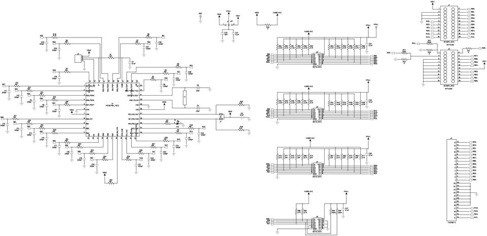
9 INTF3000 Interface Board Evaluates: EV Kits Requiring SPI/Parallel to USB Interface Component Information, PCB Files, and Schematic See the following links for component information, PCB files, and schematic. INTF3000 EV BOM INTF3000 EV PCB Files INTF3000 EV Schematic Note: All design files provided are intended to be used as reference only. Ordering Information PART INTF3000+ TYPE EVKIT Maxim Integrated 9

10 INTF3000 Interface Board Evaluates: EV Kits Requiring SPI/Parallel to USB Interface Revision History REVISION NUMBER REVISION DATE DESCRIPTION PAGES CHANGED 0 11/15 Initial release For pricing, delivery, and ordering information, please contact Maxim Direct at , or visit Maxim Integrated s website at Maxim Integrated cannot assume responsibility for use of any circuitry other than circuitry entirely embodied in a Maxim Integrated product. No circuit patent licenses are implied. Maxim Integrated reserves the right to change the circuitry and specifications without notice at any time. Maxim Integrated and the Maxim Integrated logo are trademarks of Maxim Integrated Products, Inc Maxim Integrated Products, Inc. 10

11 PART QTY DESCRIPTION C1, C3, C31, C34, C35, C36, C uF 10% 0603 Capacitor Murata GRM188R71C104K C2, C6, C7, C8, C9, C10, C11, C12, C13, C14, C15, C16, C17, C18, C19, C20, C21, C22, C23, C24, C25, C26, C27, C28, C29, C30, C33 C4, C pF 10% 0402 Capacitor Murata GRM155R71H331K 330pF 10% 0402 Capacitor Murata GRM155R71H331K C nF 10% Capacitor Murata GRM155R71E103K R K 5% 0402 Resistor R2, R3, R4, R5, R6, R7, R8, R9, R10, R11, R12, R13, R14, R15, R16, R17, R18, R19, R20, R21, R22, R23, R24, R25, R26, R27, R28, R48, R ohms 5% 0402 Resistor R29, R30, R31, R38, R39, R40, R54, R56, R58, R59, R61, R K 5% 0402 Resistor R32, R33, R34, R35, R36, R37, R49, R50, R52, R53, R55, R57, R60, R62, R70, R74, R75, R76, R77, R80, R88, R K 5% 0402 Resistor R41, R43, R45, R Resistor R42, R43, R44, R45, R65, R66 R71, R72, R73, R83, R85, R Open 0402 Resistor 51K 5% 0402 Resistor D1 1 LIGHT EMITTING DIODE Fairchild MV8741 U1 1 PIC MICROCONTROLLER MICROCHIP TECHNOLOGY PIC16C765-I/PT U2, U3, U4, U5 4 Hex Buffer/Driver OC Texas Instruments SN74LV07AD Y1 J1, J3 J4 J6, J MHz Crystal ECS, Inc. ECS PX-TR 2X10 Header 2.54MM, Comes in X 2 Pin Strips (CUT TO FIT) Sullins PEC36DAAN DB25 F PCB CONN HD- 20 SERIES AMP X2 Header 2-Pin Header 0.1" Centers - Cut to fit Sullins PEC36SAAN 1X3 Header JU1 J Pin Header 0.01" Centers - Cut to fit Sullins PEC36SAAN USB Connector - B Type ASSMANN Electronics AU-Y1007-R 1 Testpoint - PC Mini-Black Keystone 5001 VPULL 1 Testpoint - PC Mini-Red Keystone 5000

12

13

14
15
16
17
18
19
+Denotes lead-free and RoHS-compliant.
 19-4040; Rev 0; 2/08 MAX7474 Evaluation Kit General Description The MAX7474 evaluation kit (EV kit) is a fully assembled and tested printed-circuit board (PCB) that configures the MAX7474 IC for automatically
+Denotes lead-free and RoHS-compliant. C5 C10, C17, C18
 19-0623; Rev 1; 3/08 Maxim MINIQUSB User Guide General Description The Maxim command module (MINIQUSB) receives commands from a PC through the USB to create an SPI or SMBus /I 2 C-compatible interface.
Designing VM2 Application Boards
 Designing VM2 Application Boards This document lists some things to consider when designing a custom application board for the VM2 embedded controller. It is intended to complement the VM2 Datasheet. A
MAX6683 Evaluation System/Evaluation Kit
 19-2343; Rev 1; 3/07 MAX6683 Evaluation System/Evaluation Kit General Description The MAX6683 evaluation system (EV system) consists of a MAX6683 evaluation kit (EV kit) and a companion Maxim CMODUSB board.
MAX17061A Evaluation Kit/Evaluation System
 19-4654; Rev 0; 5/09 MAX17061A Evaluation Kit/Evaluation System General Description The MAX17061A evaluation system (EV system) consists of the MAX17061A evaluation kit (EV kit) and the Maxim CMAXQUSB+
ARDUINO SEVERINO SERIAL SINGLE SIDED VERSION 3 S3v3 (REVISION 2) USER MANUAL
 USER MANUAL") ARDUINO SEVERINO SERIAL SINGLE SIDED VERSION 3 S3v3 (REVISION 2) USER MANUAL X1: DE-9 serial connector Used to connect computer (or other devices) using RS-232 standard. Needs a serial cable, with at least
ARDUINO SEVERINO SERIAL SINGLE SIDED VERSION 3 S3v3 (REVISION 2) USER MANUAL X1: DE-9 serial connector Used to connect computer (or other devices) using RS-232 standard. Needs a serial cable, with at least
Data Sheet. Adaptive Design ltd. Arduino Dual L6470 Stepper Motor Shield V1.0. 20 th November 2012. L6470 Stepper Motor Shield
 Arduino Dual L6470 Stepper Motor Shield Data Sheet Adaptive Design ltd V1.0 20 th November 2012 Adaptive Design ltd. Page 1 General Description The Arduino stepper motor shield is based on L6470 microstepping
AN-812 APPLICATION NOTE
 AN- APPLICATION NOTE One Technology Way P.O. Box 90 Norwood, MA 00-90, U.S.A. Tel: 7.9.700 Fax: 7.. www.analog.com Microcontroller-Based Serial Port Interface (SPI ) Boot Circuit by Alfredo Barriga INTRODUCTION
Switch board datasheet EB007-00-1
 Switch board datasheet EB007-00-1 Contents 1. About this document... 2 2. General information... 3 3. Board layout... 4 4. Testing this product... 5 5. Circuit description... 6 Appendix 1 Circuit diagram
PolyBot Board. User's Guide V1.11 9/20/08
 PolyBot Board User's Guide V1.11 9/20/08 PolyBot Board v1.1 16 pin LCD connector 4-pin SPI port (can be used as digital I/O) 10 Analog inputs +5V GND GND JP_PWR 3-pin logic power jumper (short top 2 pins
MAX5417L Evaluation Kit/Evaluation System
 19-3733; Rev 0; 6/05 MAX5417L Evaluation Kit/Evaluation System General Description The MAX5417L evaluation system (EV system) consists of a MAX5417L evaluation kit (EV kit) and a companion command module
DKWF121 WF121-A 802.11 B/G/N MODULE EVALUATION BOARD
 DKWF121 WF121-A 802.11 B/G/N MODULE EVALUATION BOARD PRELIMINARY DATA SHEET Wednesday, 16 May 2012 Version 0.5 Copyright 2000-2012 Bluegiga Technologies All rights reserved. Bluegiga Technologies assumes
MFRD52x. Mifare Contactless Smart Card Reader Reference Design. Document information
 Rev. 2.1 17. April 2007 Preliminary Data Sheet Document information Info Keywords Content MFRC522, MFRC523, MFRC52x, MFRD522, MFRD523, Mifare Contactless Smart Card Reader Reference Design, Mifare Reader
WICE-SPI Hardware Operation Manual
 Contents 1.Hardware Instruction...1 2. Pin Definition Of WICE-SPI Connector...2 3. Peripheral Circuit Arrangements...3 4. On-Board Programming...4 5. Off-Line Programming...8 1.Hardware Instruction 1.WICE-SPI
ic-mq EVAL MQ1D EVALUATION BOARD DESCRIPTION
 Rev A3, Page 1/7 ORDERING INFORMATION Type Order Designation Description and Options Evaluation Board ic-mq EVAL MQ1D ic-mq Evaluation Board ready to operate, accessible through GUI via PC adapter Software
Fairchild Solutions for 133MHz Buffered Memory Modules
 AN-5009 Fairchild Semiconductor Application Note April 1999 Revised December 2000 Fairchild Solutions for 133MHz Buffered Memory Modules Fairchild Semiconductor provides several products that are compatible
BrightSign Expander Hardware Guide
 Hardware Guide PCBA: Rev C Version: 0.1 Saratoga, CA, USA 1 Table of Contents OVERVIEW... 3 EXPANDER BLOCK DIAGRAM... 4 PORTS... 6 POWER CONNECTOR... 6 OPTICAL SPDIF CONNECTOR... 6 DB25 SWITCH/LED CONNECTOR...
QUICK START GUIDE FOR DEMONSTRATION CIRCUIT 956 24-BIT DIFFERENTIAL ADC WITH I2C LTC2485 DESCRIPTION
 LTC2485 DESCRIPTION Demonstration circuit 956 features the LTC2485, a 24-Bit high performance Σ analog-to-digital converter (ADC). The LTC2485 features 2ppm linearity, 0.5µV offset, and 600nV RMS noise.
USB I/O CONTROL BOX 8 relays, 8 digital I/O lines and 8 HV inputs
 USB I/O CONTROL BOX 8 relays, 8 digital I/O lines and 8 HV inputs The Big Deal USB HID device compatible with 32/64 Bit operating systems 8 TTL/LVTTL digital I/O channels, 8 High Voltage digital inputs
EVAL-AD5680. Single Channel, 18-Bit, Serial Input, Voltage Output DAC Evaluation Board FEATURES GENERAL DESCRIPTION
 Single Channel, 18-Bit, Serial Input, Voltage Output DAC Evaluation Board EVAL-AD680 FEATURES Full-featured evaluation board for AD680 On-board reference On-board ADC for voltage readback Various link
The Programming Interface
 : In-System Programming Features Program any AVR MCU In-System Reprogram both data Flash and parameter EEPROM memories Eliminate sockets Simple -wire SPI programming interface Introduction In-System programming
8-Bit Microcontroller with Flash. Application Note. Using a Personal Computer to Program the AT89C51/C52/LV51/LV52/C1051/C2051
 Using a Personal Computer to Program the ATC/C/LV/LV/C0/C0 Introduction This application note describes a personal computer-based programmer for the ATC/C/LV/LV/C0/C0 Flash-based s. The programmer supports
DEMO MANUAL DC1338B LTC2990 I 2 C Temperature Voltage and Current Monitor DESCRIPTION
 DEMO MANUAL DC8B LTC990 I C Temperature Voltage and Current Monitor DESCRIPTION Demonstration circuit 8B features the LTC 990, a high performance temperature, voltage and current monitor that uses I C
Massachusetts Institute of Technology Department of Electrical Engineering and Computer Science 6.115 Microprocessor Project Laboratory
 Massachusetts Institute of Technology Department of Electrical Engineering and Computer Science 6.115 Microprocessor Project Laboratory Connecting your PSoC Evaluation Board It is easy and fun to avoid
Microstep Driver Manual Version 6/13/2006
 Microstep Driver Manual Version 6/13/2006 Embedded Acquisition Systems 2517 Cobden Street Sterling Heights, MI 48310 http://www.embeddedtronics.com email [email protected] copyright 2003-2004 EAS
PCAN-MicroMod Evaluation Test and Development Environment for the PCAN-MicroMod. User Manual. Document version 2.0.1 (2013-08-06)
") PCAN-MicroMod Evaluation Test and Development Environment for the PCAN-MicroMod User Manual Document version.0. (0-0-0) Products taken into account Product Name Part number Model PCAN-MicroMod Evaluation
PCAN-MicroMod Evaluation Test and Development Environment for the PCAN-MicroMod User Manual Document version.0. (0-0-0) Products taken into account Product Name Part number Model PCAN-MicroMod Evaluation
Pmod peripheral modules are powered by the host via the interface s power and ground pins.
 Digilent Pmod Interface Specification Revision: November 20, 2011 1300 NE Henley Court, Suite 3 Pullman, WA 99163 (509) 334 6306 Voice (509) 334 6300 Fax Introduction The Digilent Pmod interface is used
Maxim Integrated Products 1
 -; Rev ; /0 MAX Evaluation Kit General Description The MAX evaluation kit (EV kit) is an assembled and tested printed circuit board (PCB) that demonstrates the MAX SPI -interfaced four-digit x matrix LED
How To Program A Microcontroller Board (Eb064) With A Psp Microcontroller (B064-74) With An Ios 2.5V (Power) And A Ppt (Power Control) (Power Supply) (
 With A Psp Microcontroller (B064-74) With An Ios 2.5V (Power) And A Ppt (Power Control) (Power Supply) (") dspic / PIC24 Multiprogrammer datasheet EB064-00 00-1 Contents 1. About this document... 2 2. General information... 3 3. Board layout... 4 4. Testing this product... 5 5. Circuit description... 6 Appendix
dspic / PIC24 Multiprogrammer datasheet EB064-00 00-1 Contents 1. About this document... 2 2. General information... 3 3. Board layout... 4 4. Testing this product... 5 5. Circuit description... 6 Appendix
XPort Universal Demo Board User Guide
 XPort Universal Demo Board User Guide Part Number 900-563 Revision A September 2009 Copyright and Trademark Contacts 2009 Lantronix. All rights reserved. No part of the contents of this book may be transmitted
Fiber Optic Monitor and Control Evaluation Kit
 Rev 0; 05/04 Fiber Optic Monitor and Control Evaluation Kit General Description The fiber optic monitor and control evaluation kit (EV kit) provides a hardware and software interface for evaluating the
PICNet 1. PICNet 1 PIC18 Network & SD/MMC Development Board. Features. Applications. Description
 Features PICNet 1 PIC18 Network & SD/MMC Development Board IC Sockets for 28 or 40-pin Microchip PIC18F Microcontrollers IC Socket for 8-pin serial EEPROM Multiple MCU Oscillator sources Full 10BaseT IEEE
EasyPIC4 User s Manual
 SOFTWARE AND HARDWARE SOLUTIONS FOR THE EMBEDDED WORLD MikroElektronika - Books - Compilers User s Manual PIC MICROCHIP DEVELOPMENT BOARD 3in1 mikro IN-CIRCUIT DEBUGGER USB 2.0 IN-CIRCUIT PROGRAMMER With
8 by 8 dot matrix LED displays with Cascadable Serial driver B32CDM8 B48CDM8 B64CDM8 General Description
 8 by 8 dot matrix LED displays with Cascadable Serial driver B32CDM8 B48CDM8 B64CDM8 General Description The B32CDM8, B48CDM8 and the B64CDM8 are 8 by 8 (row by column) dot matrix LED displays combined
ELAN DIGITAL SYSTEMS LTD. SL232 PC- CARD USER S GUIDE
 ELAN DIGITAL SYSTEMS LTD. LITTLE PARK FARM ROAD, SEGENSWORTH WEST, FAREHAM, HANTS. PO15 5SJ. TEL: (44) (0)1489 579799 FAX: (44) (0)1489 577516 e-mail: [email protected] website: http://www.pccard.co.uk
USB / Data-Acquisition Module NOW LEAD-FREE
 USB / Data-Acquisition Module NOW LEAD-FREE DLP-TEMP-G Features: Digital I/Os, Analog Inputs (0- Volts) or any combination USB. and.0 Compatible Interface th Generation Silicon from FTDI Supports Up To
CAN bus board. www.matrixmultimedia.com EB018
 CAN bus board www.matrixmultimedia.com EB018 Contents About this document 3 Board layout 3 General information 4 Circuit description 5 Protective cover 6 Circuit diagram 7 2 Copyright About this document
POCKET SCOPE 2. The idea 2. Design criteria 3
 POCKET SCOPE 2 The idea 2 Design criteria 3 Microcontroller requirements 3 The microcontroller must have speed. 3 The microcontroller must have RAM. 3 The microcontroller must have secure Flash. 3 The
Schematic & Parts List: PIC16F688 Satellite Tracker & Rotor Controller
 Fox Delta Amateur Radio Projects & Kits FD- ST1 Schematic & Parts List: PIC16F688 Satellite Tracker & Rotor Controller Introduction to Satellite Antenna Tracking: In view to encourage radio amateurs and
MX PIC24F Educational Module User Manual
 MX PIC24F Educational Module User Manual Revision History Date Description Initial release. Table of Contents 1. Introduction... 3 1.1. Package Contents... 3 1.2. Key Hardware Features... 4 2. Hardware
USBSPYDER08 Discovery Kit for Freescale MC9RS08KA, MC9S08QD and MC9S08QG Microcontrollers User s Manual
 USBSPYDER08 Discovery Kit for Freescale MC9RS08KA, MC9S08QD and MC9S08QG Microcontrollers User s Manual Copyright 2007 SofTec Microsystems DC01197 We want your feedback! SofTec Microsystems is always on
Real Time Clock USB Evaluation Board V3.0
 Real Time Clock USB Evaluation Board V.0 Application Note February 9, 008 RTC EVB Intersil RTC Devices Supported Introduction This evaluation board provides a platform for testing Intersil Real Time Clock
User s Manual of Board Microcontroller ET-MEGA2560-ADK ET-MEGA2560-ADK
 User s Manual of Board Microcontroller ET-MEGA2560-ADK ET-MEGA2560-ADK Because Arduino that is the development project on AVR MCU as Open Source has been published, it is popular and widespread shortly.
Schematic & Parts List: PIC16F688 Satellite Tracker & Rotor Controller
 Fox Delta Amateur Radio Projects & Kits FD- ST1 Schematic & Parts List: PIC16F688 Satellite Tracker & Rotor Controller Introduction to Satellite Antenna Tracking: The ST1 kit/project was designed as an
JTAG-HS2 Programming Cable for Xilinx FPGAs. Overview. Revised January 22, 2015 This manual applies to the HTAG-HS2 rev. A
 1300 Henley Court Pullman, WA 99163 509.334.6306 www.digilentinc.com Programming Cable for Xilinx FPGAs Revised January 22, 2015 This manual applies to the HTAG-HS2 rev. A Overview The Joint Test Action
ALL-USB-RS422/485. User Manual. USB to Serial Converter RS422/485. ALLNET GmbH Computersysteme 2015 - Alle Rechte vorbehalten
 ALL-USB-RS422/485 USB to Serial Converter RS422/485 User Manual ALL-USB-RS422/485 USB to RS-422/485 Plugin Adapter This mini ALL-USB-RS422/485 is a surge and static protected USB to RS-422/485 Plugin Adapter.
Controlling a Dot Matrix LED Display with a Microcontroller
 Controlling a Dot Matrix LED Display with a Microcontroller By Matt Stabile and programming will be explained in general terms as well to allow for adaptation to any comparable microcontroller or LED matrix.
DATASHEET. ADAM Arduino Display Adaptor Module. Arduino Compatible Shield P/N: 4Display-Shield-FT843 For the 4D Systems 4DLCD-FT843 Display
 DATASHEET ADAM Arduino Display Adaptor Module Arduino Compatible Shield P/N: 4Display-Shield-FT843 For the 4D Systems 4DLCD-FT843 Display Document Date: 8 th January 2014 Document Revision: 1.0 Uncontrolled
EVALUATION KIT AVAILABLE Broadband, Two-Output, Low-Noise Amplifier for TV Tuner Applications MAX2130. Maxim Integrated Products 1
 9-86; Rev ; 8/ EVALUATION KIT AVAILABLE Broadband, Two-Output, Low-Noise General Description The broadband, low-distortion, low-noise, two-output amplifier performs preamp, loop-out, and buffer functions
K8048 PIC PROGRAMMER BOARD
 K8048 PIC PROGRAMMER BOARD Velleman Kits Welcome to the exciting world of Velleman Kits. Velleman Kit is known all over the world for our High Quality electronic kits. Our range goes from easy to build
AND8336. Design Examples of On Board Dual Supply Voltage Logic Translators. Prepared by: Jim Lepkowski ON Semiconductor. http://onsemi.
 Design Examples of On Board Dual Supply Voltage Logic Translators Prepared by: Jim Lepkowski ON Semiconductor Introduction Logic translators can be used to connect ICs together that are located on the
Model 201 Wiegand Touchpad Reader Installation Guide
 Model 201 Wiegand Touchpad Reader Installation Guide P/N 460353001C 15AUG11 2011 UTC Fire & Security. All rights reserved. This document may not be copied in whole or in part or otherwise reproduced without
KTA-223 Arduino Compatible Relay Controller
 8 Relay Outputs 5A 250VAC 4 Opto-Isolated Inputs 5-30VDC 3 Analog Inputs (10 bit) Connections via Pluggable Screw Terminals 0-5V or 0-20mA Analog Inputs, Jumper Selectable 5A Relay Switching Power Indicator
DS9490R/DS9490B USB to 1-Wire/iButton Adapters
 9-488; Rev 6/ FEATURES High-Speed Mbps Universal Serial Bus (USB) Interface Supports Standard and Overdrive -Wire Communication Slew-Rate-Controlled -Wire Timing and Active Pullup for Improved -Wire Network
DK40 Datasheet & Hardware manual Version 2
 DK40 Datasheet & Hardware manual Version 2 IPC@CHIP DK40 Evaluation module Beck IPC GmbH http://www.bcl.de page 1 of 11 Table of contents Table of contents... 2 Basic description... 3 Characteristics...
GTS-4E Hardware User Manual. Version: V1.1.0 Date: 2013-12-04
 GTS-4E Hardware User Manual Version: V1.1.0 Date: 2013-12-04 Confidential Material This document contains information highly confidential to Fibocom Wireless Inc. (Fibocom). Fibocom offers this information
RC2200DK Demonstration Kit User Manual
 Demonstration Kit User Manual Table of contents TABLE OF CONTENTS... 1 QUICK INTRODUCTION... 2 INTRODUCTION... 3 DEMONSTRATION BOARD... 4 POWER SUPPLY SECTION... 5 RS-232 INTERFACE... 6 CONNECTORS... 7
SM1231 USER GUIDE SM1231 RF MODULE USER GUIDE
 SM1231 RF MODULE Revision 1.0 11/2009 Page 1 of 8 www.semtech.com Table of Contents Table of Contents...2 Index of Figures...2 Index of Tables...2 1 Introduction...3 2 Reference Design...3 3 PCB Layout...6
CryptoAuth Xplained Pro
 CryptoAuth Xplained Pro CryptoAuthentication Xplained Pro Extension Board HARDWARE USER GUIDE Atmel CryptoAuth Xplained Pro Extension Board Introduction The Atmel CryptoAuth Xplained Pro (CAXPro) Evaluation
Thermostat Application Module Kit
 Thermostat Application Module Kit PUG0040-00 Product User Guide Kit Contents Overview Thermostat Application Module CD-ROM: Software Examples and Documentation The Thermostat Application Module provides
Hardware Connections between Arduino and IMU Nori Wilkins Apr. 5, 2013
 Hardware Connections between Arduino and IMU Nori Wilkins Apr. 5, 2013 Abstract Sensors are commonly used throughout many world wide applications. Out of many sensors that are used, the inertial measurement
FlowKit in-circuit debug system
 FlowKit in-circuit debug system www.matrixmultimedia.com HP299 Contents About this document 3 Board layout 3 General information 4 Detailed operation 4 Circuit diagram 7 2 Copyright About this document
EGR 278 Digital Logic Lab File: N278L3A Lab # 3 Open-Collector and Driver Gates
 EGR 278 Digital Logic Lab File: N278L3A Lab # 3 Open-Collector and Driver Gates A. Objectives The objectives of this laboratory are to investigate: the operation of open-collector gates, including the
Future Technology Devices International Ltd
 Future Technology Devices International Ltd Datasheet UMFT200XD Breakout Modules 1 Introduction UMFT200XD is a USB to I 2 C breakout module The UMFT200XD breakout module utilizes FTDI s FT200XQ IC to convert
UIM2901-5A MACH3 breakout board
 User Manual UIM2901-5A MACH3 Breakout Board UIM2901-5A MACH3 Breakout Board UIM2901-5A MACH3 breakout board Features General DB25 interface between PC and user device Fully buffered opto-isolated I/O (Input
XBee USB Adapter Board (#32400)
") Web Site: www.parallax.com Forums: forums.parallax.com Sales: [email protected] Technical: [email protected] Office: (916) 624-8333 Fax: (916) 624-8003 Sales: (888) 512-1024 Tech Support: (888) 997-8267
Web Site: www.parallax.com Forums: forums.parallax.com Sales: [email protected] Technical: [email protected] Office: (916) 624-8333 Fax: (916) 624-8003 Sales: (888) 512-1024 Tech Support: (888) 997-8267
STF201-22 & STF201-30
 Description The STF201 is a combination EMI filter and line termination device with integrated TVS diodes for use on downstream USB ports. It is constructed using a proprietary technology that allows passive
ABACOM - netpio. http://www.abacom-online.de/div/setup_netpio.exe
 ABACOM - netpio Download http://www.abacom-online.de/div/setup_netpio.exe The ABACOM netpio board is a 10Mbit network interface designed for measurement and control applications. The board is available
Programming PIC Microcontrollers in PicBasic Pro Lesson 1 Cornerstone Electronics Technology and Robotics II
 Programming PIC Microcontrollers in PicBasic Pro Lesson 1 Cornerstone Electronics Technology and Robotics II Administration: o Prayer PicBasic Pro Programs Used in This Lesson: o General PicBasic Pro Program
revolution Contents: Introduction Power 28-pin Project Board with input/output cables
 28-PIN IN IN PROJECT BOARD Contents: AXE020 28-pin Project Board with input/output cables Introduction The 28-pin project board is designed to allow rapid prototyping with 28-pin PICAXE microcontrollers.
Symbol Parameters Units Frequency Min. Typ. Max. 850 MHz 14.8 16.3 17.8
 Product Description Sirenza Microdevices SGC-689Z is a high performance SiGe HBT MMIC amplifier utilizing a Darlington configuration with a patented active-bias network. The active bias network provides
USB to RS-422/485 Serial Adapter
 USB to RS-422/485 Serial Adapter User Manual Ver. 2.00 All brand names and trademarks are properties of their respective owners. Contents: Chapter 1: Introduction... 3 1.1 Product Introduction... 3 1.2
In-System Programming Design TM. Guidelines for ispjtag Devices. Introduction. Device-specific Connections. isplsi 1000EA Family.
 In-System Design TM February 2002 Introduction In-system programming (ISP ) has often been billed as a direct replacement for configuring a device through a programmer. The idea that devices can simply
RGB for ZX Spectrum 128, +2, +2A, +3
 RGB for ZX Spectrum 128, +2, +2A, +3 Introduction... 2 Video Circuitry... 3 Audio Circuitry... 8 Lead Wiring... 9 Testing The Lead... 11 Spectrum +2A/+3 RGB Differences... 12 Circuitry Calculations...
GSM Interfacing Board
 Campus Component Pvt. Ltd. DISCLAIMER Information furnished is believed to be accurate and reliable at the time of publication. However, Campus Component Pvt. Ltd. assumes no responsibility arising from
UM1613 User manual. 16-pin smartcard interface ST8034P demonstration board. Introduction
 User manual 16-pin smartcard interface ST8034P demonstration board Introduction The purpose of this document is to describe, and provide information on, how to efficiently use the ST8034P smartcard interface
Ocean Controls RC Servo Motor Controller
 Ocean Controls RC Servo Motor Controller RC Servo Motors: RC Servo motors are used in radio-controlled model cars and planes, robotics, special effects, test equipment and industrial automation. At the
Modular I/O System Analog and Digital Interface Modules
 OPERATING INSTRUCTIONS Modular I/O System Analog and Digital Interface Modules Installation Operation Maintenance Document Information Document ID Title: Operating Instructions Modular I/O System Part
How To Use An Ams 5812 Pressure Sensor With A Usb Starter Kit
 User Guide USB Starter Kit AMS 5812 Phone:+49 (0)6131/91 0730-0 Fax: +49 (0)6131/91 073-30 Internet: E Mail: [email protected] Analog Microelectronics GmbH An der Fahrt 13, D 55124 Mainz May 2012 - Rev.
TURBO PROGRAMMER USB, MMC, SIM DEVELOPMENT KIT
 TURBO PROGRAMMER USB, MMC, SIM DEVELOPMENT KIT HARDWARE GUIDE This document is part of Turbo Programmer documentation. For Developer Documentation, Applications and Examples, see http:/// PRELIMINARY (C)
EVAL-AD5390/91/92EB. Evaluation Board for 8-/16-Channel, 12-/14-Bit, Serial Input, Voltage-Output DACs
 Evaluation Board for 8-/16-Channel, 12-/14-Bit, Serial Input, Voltage-Output DACs EVAL-AD5390/91/92EB FEATURES Full-featured evaluation board On-board reference On-board ADC for MON_OUT voltage readback
UniPi technical documentation REV 1.1
 technical documentation REV 1.1 Contents Overview... 2 Description... 3 GPIO port map... 4 Power Requirements... 5 Connecting Raspberry Pi to UniPi... 5 Building blocks... 5 Relays... 5 Digital Inputs...
Wireless Temperature
 Wireless Temperature connected freedom and Humidity Sensor Using TELRAN Application note TZ1053AN-06 Oct 2011 Abstract Dr. C. Uche This application note describes the complete system design (hardware and
ABB Drives. User s Manual HTL Encoder Interface FEN-31
 ABB Drives User s Manual HTL Encoder Interface FEN-31 HTL Encoder Interface FEN-31 User s Manual 3AUA0000031044 Rev B EN EFFECTIVE: 2010-04-06 2010 ABB Oy. All Rights Reserved. 5 Safety instructions
Advanced Data Capture and Control Systems
 Advanced Data Capture and Control Systems Tronisoft Limited Email: [email protected] Web: www.tronisoft.com RS232 To 3.3V TTL User Guide RS232 to 3.3V TTL Signal Converter Modules P/N: 9651 Document
ICS650-44 SPREAD SPECTRUM CLOCK SYNTHESIZER. Description. Features. Block Diagram DATASHEET
 DATASHEET ICS650-44 Description The ICS650-44 is a spread spectrum clock synthesizer intended for video projector and digital TV applications. It generates three copies of an EMI optimized 50 MHz clock
DOSISYS. Hands Free Reader LDM 210 - LDM 220. User Manual 127356A
 DOSISYS LDM 210 - LDM 220 Hands Free Reader User Manual 127356A Publication, translation and reproduction total or partial of this document is strictly forbidden without authorization MGP Instruments
Arduino ADK Back. For information on using the board with the Android OS, see Google's ADK documentation.
 Arduino ADK Arduino ADK R3 Front Arduino ADK R3 Back Arduino ADK Front Arduino ADK Back Overview The Arduino ADK is a microcontroller board based on the ATmega2560 (datasheet). It has a USB host interface
Whale 3. User Manual and Installation Guide. DC Servo drive. Contents. 1. Safety, policy and warranty. 1.1. Safety notes. 1.2. Policy. 1.3. Warranty.
 Whale 3 DC Servo drive User Manual and Installation Guide Contents 1. Safety, policy and warranty. 1.1. Safety notes. 1.2. Policy. 1.3. Warranty. 2. Electric specifications. 2.1.Operation ranges. 3. Connections
Lab 3: PCB design with EAGLE
 In this lab you will design a PCB board that will replace all the wires and boards you ve used in the first two labs. 1. Pre-Lab On the website are two EAGLE tutorials. Do them both. Q1. For the first
USB-Blaster Download Cable User Guide
 USB-Blaster Download Cable User Guide Subscribe UG-USB81204 101 Innovation Drive San Jose, CA 95134 www.altera.com TOC-2 Contents Introduction to USB-Blaster Download Cable...1-1 USB-Blaster Revision...1-1
UM1724 User manual. STM32 Nucleo boards. Introduction
 User manual STM32 Nucleo boards Introduction The STM32 Nucleo board (NUCLEO-F030R8, NUCLEO-F072RB, NUCLEO-F103RB, NUCLEO-F302R8, NUCLEO-F334R8, NUCLEO-F401RE, NUCLEO-F411RE, NUCLEO- L053R8, NUCLEO-L152RE)
Total solder points: 167 Difficulty level: beginner 1 2 3 4 5 advanced DMX CONTROLLED RELAY K8072 ILLUSTRATED ASSEMBLY MANUAL
 Total solder points: 167 Difficulty level: beginner 1 2 3 4 5 advanced DMX CONTROLLED RELAY K8072 Control a relay by means of the wellknown DMX512 protocol. ILLUSTRATED ASSEMBLY MANUAL H8072IP-1 Features
TEECES DOME LIGHTING SYSTEMS
 This lighting system was designed by John V (Teeces) to be a simple, customizable, expandable and affordable solution for dome lighting. An Arduino micro-controller is used to tell LED driver chips which
1-Port R422/485 Serial PCIe Card
 1-Port R422/485 Serial PCIe Card Installation Guide 1. Introduction Thank you for purchasing this 1-Port RS422/485 Serial PCI Express (PCIe) Card. It is a universal add in card that connects to a PC or
VDIP1. Vinculum VNC1L Module. Datasheet
 Future Technology Devices International Ltd. VDIP1 Vinculum VNC1L Module Datasheet Version 1.02 Issue Date: 2010-05-31 Future Technology Devices International Ltd (FTDI) Unit 1, 2 Seaward Place, Centurion
DS2149DK/DS21349DK T1/J1 Line Interface Unit Design Kit
 www.maxim-ic.com GENERAL DESCRIPTION The DS2149DK/DS21349DK is a fully integrated design kit for the DS2149 and the DS21349 T1/J1 line interface units (LIUs). It contains the necessary circuitry to evaluate
2-Port RS232/422/485 Combo Serial to USB2.0 Adapter (w/ Metal Case and Screw Lock Mechanism) Installation Guide
 Installation Guide") 2-Port RS232/422/485 Combo Serial to USB2.0 Adapter (w/ Metal Case and Screw Lock Mechanism) Installation Guide 1. Introduction Thank you for purchasing this 2-Port RS232/422/485 Combo Serial to USB Adapter.
2-Port RS232/422/485 Combo Serial to USB2.0 Adapter (w/ Metal Case and Screw Lock Mechanism) Installation Guide 1. Introduction Thank you for purchasing this 2-Port RS232/422/485 Combo Serial to USB Adapter.
ET-BASE AVR ATmega64/128
 ET-BASE AVR ATmega64/128 ET-BASE AVR ATmega64/128 which is a Board Microcontroller AVR family from ATMEL uses MCU No.ATmega64 and ATmega128 64PIN. Board ET-BASE AVR ATmega64/128 uses MCU s resources on