WGL20, WGL20H, WGL20F Grinder Pumps
|
|
|
- Gillian Greene
- 9 years ago
- Views:
Transcription
1 WGL20, WGL20H, WGL20F Grinder Pumps Installation and Service Manual 2012 Pentair Pump Group, Inc A032 03/12

2 Thank you for purchasing your Myers Pump. To help ensure years of trouble-free operation, please read the following manual carefully. CAUTION: Read these safety warnings first before installing, servicing, or operating any pump. SAFETY WARNINGS: Before Installation: This manual contains important information for the safe use of this product. Read this manual completely and follow the instructions carefully. Reasonable care and safe methods relating to the installation and operation of this product should be practiced. Check local codes and requirements before installation. MUST BE INSTALLED BY EXPERIENCED PROFESSIONALS ONLY DANGER: Risk of Electrical Shock or Electrocution. May result in serious injury or death or fire hazard. Installer must disconnect all electrical sources prior to installation, handling or servicing. Only qualified personnel may install this system. NFPA 70/National Electric Code (NEC) or local codes must be followed. System must be properly grounded according to NEC. Do not lift pump by power cord. DANGER: Biohazard Risk. Once wastewater source has been connected to system, biohazard risk exists. Installer(s) and/or service personnel must use proper personal protective equipment and follow handling procedures per OSHA 29 CFR when handling equipment after wastewater source has been connected to system. DANGER: Risk of Asphyxiation. Installer(s) and/ or service personnel must use proper personal protective equipment and follow OSHA 29 CFR or OSHA 29 CFR Pump may be installed in a location classified as a confined space. DANGER: Risk of Fire or Explosion. Do not smoke or use open flames in or around this system. This system is not intended for use in hazardous locations per NFPA 70 National Electric Code. Do not pump flammable liquids. Consult factory for optional equipment rated for hazardous location use. DANGER: Cutting Risk. Risk of serious cutting or amputation exists. Disconnect all power sources prior to servicing pump or grinding mechanism. Pump may start without warning. Grinding mechanism is extremely sharp. Use caution when handling grinder mechanism. DO NOT modify the cord strain relief. When wiring to a system control, connect the pump ground lead to the system ground. DO NOT run the pump dry. Dry running can overheat the pump (causing burns to anyone handling it) and will void the warranty. The pump normally runs hot. To avoid burns, allow it to cool for 30 minutes after shutdown before handling it. Submersible grinder pumps are not approved for use in swimming pools, recreational water installations, decorative fountains or any installation where human contact with the pumped fluid is common. This specialized pump is designed to incorporate a grinding mechanism to remove wastewater particulate and pump the resulting slurry from a residential structure to a collection system. ON THREE PHASE PUMPS ONLY MOTOR PROTECTION MUST BE PROVIDED BY THE INSTALLER. ALL THREE PHASE PUMPS MUST BE INSTALLED WITH MAGNETIC STARTERS HAVING THREE LEG OVERLOAD PROTECTION IN ACCORDANCE WITH THE NATIONAL ELECTRIC CODE. FOR DUPLEX INSTALLATIONS, BOTH PUMP MOTORS MUST HAVE SEPARATE OVERLOAD PROTECTION. WARNING: ONLY QUALIFIED PERSONS SHALL CONDUCT SERVICES AND INSTALLATIONS OF THIS PUMP. THE PUMP MUST BE WIRED BY A QUALIFIED ELECTRICIAN, USING AN APPROVED STARTER BOX AND SWITCHING DEVICE. PUMPS WITH SEAL LEAK DETECTORS MUST BE CONNECTED TO THE PROPER CONTROL CIRCUITRY. SEE INSTRUCTIONS MANUAL. FOR USE WITH MAXIMUM 140 F LIQUID. ACCEPTABLE FOR OUTDOOR USE. WARNING: DO NOT EXCEED WORKING LOAD LIMIT OF LIFTING ROPE OR CHAIN. DO NOT USE LIFTING ROPE OR CHAIN WHERE FAILURE COULD RESULT IN INJURY OR LOSS OF LIFE. EXAMINE ALL LIFTING DEVICES, ROPE OR CHAIN FOR DAMAGE BEFORE AND AFTER EACH LIFT. DO NOT USE ANY LIFTING DEVICES THAT ARE NOT RATED FOR AND DESIGNED TO LIFT THE WEIGHTS INVOLVED WITH THESE PUMPS. DO NOT INSTALL OR REMOVE PUMP WITH PERSON(S) IN BASIN A032 03/12 2

3 DO NOT THROW AWAY OR LOSE THIS MANUAL. Keep it in a safe place so that you may refer to it often for the continued safe operation of the product. PUMPS: 1. Keep clear of suction and discharge openings. DO NOT insert fingers in pump with power connected. 2. Make sure lifting devices are securely fastened each time before lifting pump. 3. DO NOT LIFT PUMP BY THE POWER CORD. 4. DO NOT exceed manufacturer s recommendation for maximum performance, as this could cause the motor to overheat. 5. Secure the pump in its operating position so it cannot tip over, fall or slide. 6. DO NOT pump without safety devices in place. IMPORTANT! Manufacturer is not responsible for losses, injury or death resulting from failure to observe these safety precautions, misuse or abuse of pumps or equipment. Control Panels: All Myers control panels used on these grinders are UL listed and CSA certified. Control panels mounted directly to the basin used outdoors are UL listed and CSA certified waterproof. Level Sensing Controls: Intrinsically safe type float controls are recommended for all applications. An intrinsically safe control panel relay will limit the current and voltage to the level controls. A Myers control panel can be supplied with this type circuitry. The float level controls maintain the basin sewage water level by controlling pump turn-on and turn-off level. 1. The lower turn-off control should be set so that the pump stops at approximately the top of the pump. 2. The upper turn-on control should be set above the lower turn-off control. The exact height between the two controls is determined by the number of pump starts desired and the depth of the basin. A maximum of 10 starts per hour should not be exceeded. 3. The override control is set at a specified height above the upper turn-on control. 4. The alarm control is set about 6" to 12" above the override control. 5. No control should be set above the inlet invert. Air Venting: Air tends to trap in the pump volute when water rises in the sump or when the pump is lowered into water after service. To vent off this air, a small hole is drilled into the pump volute. Be sure this vent hole is clean after any service work on pump. Usage: The WGL20 grinder pumps are for pumping domestic sewage. These pumps are not to be used for pumping commercial or industrial sewage such as from motels, schools, apartments, factories, etc A032 03/12

4 WGL20, WGL20H & WGL20F PUMP DIMENSIONS 23833A032 03/12 4

5 A032 03/12

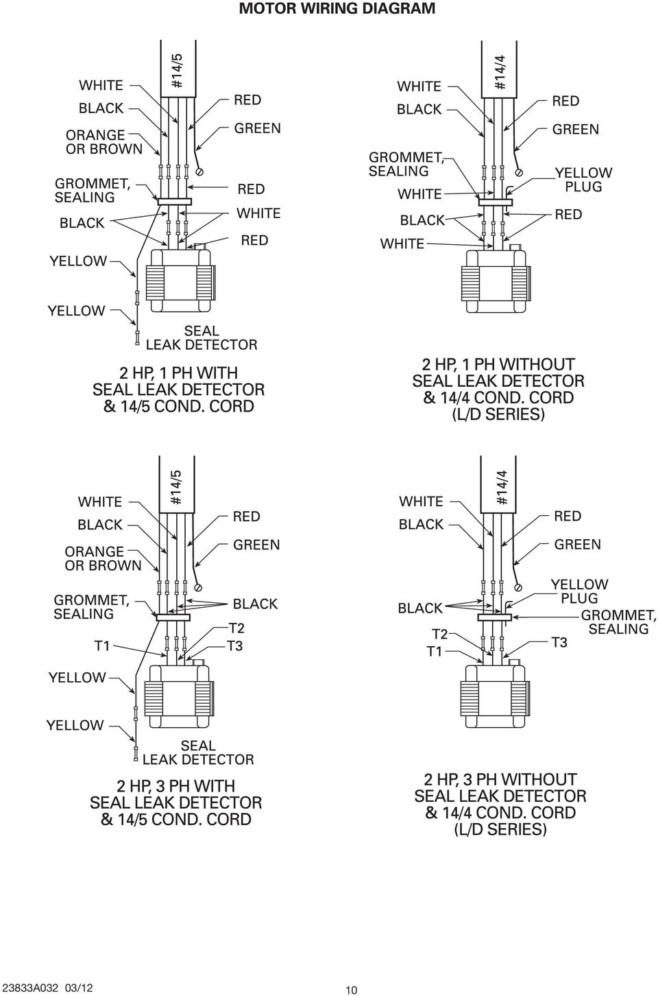
6 COMMON PARTS LIST Reference Part Number Description Qty CABLE, 4 COND. (LENGTH AS SPECIFIED, LESS DETECTOR) as spec CABLE, 5 COND. (LENGTH AS SPECIFIED, LESS DETECTOR) as spec A012 CONNECTOR, 4 COND. CABLE A001 CONNECTOR, 5 COND. CABLE C000 CAP, CORD (CASTING ONLY) A043 SCREW, MACH., #10 x 3/8" LG A015 LOCK WASHER A000 PLATE, UPPER A000 SCREW, CAP, #10 SPECIAL A000 GROMMET A000 PLATE, LOWER A169 GASKET, TETRASEAL, 3-7/8" I.D. x 1/8" A118 WIRE, RED A119 WIRE, WHITE A120 WIRE, BLACK A008K OIL, TRANSFORMER (1 GAL. CAN) 1 gal A092 PLUG, 1/4 PIPE A117 WIRE, YELLOW W/DETECTOR WIRE, PLUG, 2-1/4" W/O DETECTOR A005 WASHER, SPRING A013K BEARING, UPPER A006 RING, RETAINING D000 HOUSING, MOTOR 1 23 See Chart STATOR 1 See Chart ROTOR W/SHAFT C000 SHAFT ONLY 1 See Chart HOUSING W/STATOR A018K BEARING, LOWER A171 GASKET, 5-1/2" I.D. x 1/8" D000 HOUSING, UPPER SEAL A000 FERRULE, RUBBER A000 FERRULE, METAL A002 ELECTRODE W/DETECTOR WIRE, PLUG, 2-1/4" W/O DETECTOR A008 SCREW, SOCKET HD., 5/16" x 1" C000 HOUSING, LOWER SEAL A001 GASKET A011 SEAL, 7/8" SHAFT, UPPER A006 RING, RETAINING A010K SEAL, 7/8" LOWER D102P CASE, VOLUTE A012 SCREW, CAP, 5/16" x 1-1/4" LG C102 IMPELLER, PUMP, 5-1/2" O.D C502 IMPELLER, O.D. (AS SPECIFIED) C014 IMPELLER, HIGH HEAD DUCTILE IRON (WGL20H) C314 IMPELLER, HIGH FLOW (WGL20F) B000K IMPELLER, GRINDING A018 SCREW, FLAT HD., 1/4" x 3/4" A000 RETAINER, IMPELLER A029 SCREW, CAP, 5/16" x 1" LG A012 SCREW, CAP, 1/4" x 1" LG B002 FLANGE W/SHREDDING RING (WGL20H) B000K FLANGE W/SHREDDING RING (WGL20) B004 FLANGE W/SHREDDING RING (WGL20F) A039 SCREW, SET, 1/4" x 3/8" LG. 2 PUMP CAT. NO. (24) ROTOR W/SHAFT ROTOR ONLY HOUSING W/STATOR (23) STATOR ONLY WGL20-01 Series 24327C C200B 24325D035K 24326C100 WGL20-21Series 24327C C200B 24325D020K 24326C101 WGL20-03 Series 24327C C201B 24325D040K 24326C104 WGL20-23 Series 24327C C201B 24325D025K 24326C103 WGL20-43 Series 24327C C201B 24325D031K 24326C102 WGL20-53 Series 24327C C201B 24325D045K 24326C A032 03/12 6

7 Pump Models: The WGL20 pumps are equipped with 200 and 230 volt single phase voltages and 200, 230 and 460 volt three phase voltages; and with seal leak detector and without seal leak detector. WGL20F pumps are high flow pumps and WGL20H pumps are high head pumps. The pump model numbers are: WGL20-01, WGL20F-01, WGL20H volt single phase with seal leak detector WGL20-01 L/D, WGL20F-01 L/D, WGL20H-01 L/D 200 volt single phase without seal leak detector WGL20-21, WGL20F-21, WGL20H volt single phase with seal leak detector WGL20-21 L/D, WGL20F-21 L/D, WGL20H-21 L/D 230 volt single phase without seal leak detector WGL20-23, WGL20F-23, WGL20H volt three phase with seal leak detector WGL20-23 L/D, WGL20F-23 L/D, WGL20H-23 L/D 230 volt three phase without seal leak detector WGL20-43, WGL20F-43, WGL20H volt three phase with seal leak detector WGL20-43, WGL20F-43, WGL20H-43 L/D 460 volt three phase without seal leak detector Instructions: Instructions cover only the pump unit. Separate instructions for the electrical control panel and basin packaged system are included with these items. Complete disassembly instructions are furnished only to authorized service stations. CAUTION: PUMP IS NOT TO BE DISASSEMBLED IN THE FIELD EXCEPT AT CERTIFIED SERVICE STATIONS OR AT MYERS FACTORY. Description of Pump: Figure 1 shows cutaway of pump with parts called out. This pump is intended to grind and pump all normal sewage for home use. Pump is of heavy duty construction and submersible type for long life when pumping ground sewage. Motor is capacitor start, capacitor run for single phase. Capacitors and start relay are mounted in the electrical control box. All single phase motors must have special electrical control box furnished by Myers. INSTALLING SINGLE PHASE MOTORS WITH CONTROLS OTHER THAN MYERS VOIDS WARRANTY. Inspecting Pump: Before making any piping or electrical connections, check pump for any shipping damage and turn grinder impeller to be sure it is free. DO NOT TURN IMPELLER WITH FINGERS AS EDGES ARE SHARP. Use socket wrench in the impeller screw. CAUTION: AFTER PUMP IS INSTALLED, NEVER WORK ON MOTOR OR GRINDER UNIT WITHOUT DISCONNECTING MOTOR LEAD WIRES FROM CONTROL PANEL. DON T RELY ON OPENING CIRCUIT BREAKER ONLY. Pump has two oil-filled chambers: 1) the motor and ball bearings and 2) the seal chamber for long life and best heat transfer. The lower seal above the pump impeller acts as a buffer for upper seal that holds oil in the motor chamber. If lower seal leaks for any reason, water enters the seal chamber. If motor has the seal leak detector, the electrode will contact the water and close the circuit to the red seal light in the control panel, indicating motor must be serviced before upper seal fails. Motor Overload Protection: The single phase motor is provided with an on-winding overload switch. If motor overloads or overheats for any reason, the switch opens, stopping motor. As soon as the motor cools to normal temperature, the switch closes and restarts the motor. Three phase motors must be protected with an overload in the panel. Motor Power Cords: Pump models with the seal leak detector use a 5 conductor #14 gauge cord. The three power conductors are BLACK, WHITE and RED. The ORANGE conductor connects to the seal leak probe and GREEN conductor connects to the ground screw inside the cord cap. Single phase pumps use the BLACK and WHITE as main winding leads and the RED for the start winding. Cord Seal: The lines from the motor chamber are sealed with a rubber sealing grommet that prevents oil from leaking into the cord cap compartment. If necessary to replace power cord, the sealing grommet must not be loosened. This wire seal is removed only for complete motor repair that must be done at an authorized Myers service facility. IMPORTANT! Ground wires must be connected in the control box to grounding bar, which is connected per NEC requirements. MOTOR IS NOT SAFE UNLESS GROUNDED. Installing Pump In Sump Basin: Complete installation and piping instructions are included with the sump basin package. Single Phase Control Box: Single phase pumps must use the Myers control box. Warranty is void if other than Myers single phase control box is used A032 03/12

8 Three Phase Control Box: Any suitable three phase control equipment can be used for simplex or duplex operation. These control boxes are also available from Myers. If other than Myers box is used, overload heaters must be selected in accordance with full load amp ratings given in these instructions. Maximum Amp & Winding Resistance Values WINDING RESISTANCE IN OHMS HP SPEED VOLTS PHASE BLACK TO WHITE BLACK TO RED RED TO WHITE MAX. AMPS * If any amp readings are higher than listed, it indicates voltage may be higher or lower than normal, or that pump grinder may be clogged with trash causing extra load on motor. Resistance of Winding: Every motor winding has a fixed resistance and winding must check close to the values given in chart to operate properly. This winding resistance also shows if motor is connected for voltage being used. Use ohmmeter for this test and set on scale to read directly in ohms. TROUBLE CHECK LIST Troubles listed below are generally not caused by the pump. Other trouble can occur from faulty control box operation. These will be listed with the control box instructions. CONDITION Pump runs but does not pump liquid from basin. PROBABLE CAUSE 1. Pump impeller may be air locked; this occasionally occurs on a new installation. Start and stop pump several times to purge air. 2. Run additional water into basin so that pump will be submerged deeper to clear air. 3. If air does not clear, it may be necessary to lift pump out of sealing elbow and start motor to allow pump to pump for a few seconds. If discharge is piped in with union, slightly break union and start pump to clear air. Air vent hole is provided in pump case, so some water will flow from this hole when pump is operating. If vent hole gets clogged, clean out. 4. If pump has been installed for some time and does not pump, it may be clogged at grinder inlet. 5. Discharge gate valve may be closed. 6. Discharge check valve may be clogged or have a broken clapper. 7. Discharge head may be too high. Check elevation. Maximum pump head at zero flow is 70 feet. See pump curve A032 03/12 8

9 CONDITION Red light comes on at control box. PROBABLE CAUSE 1. This indicates some water has leaked past the lower seal and has entered the seal chamber and made contact with the electrode probe. Pump must be removed from basin for replacement of lower seal. This preventive repair will save the motor. Overload trips and alarm buzzer or flashing red light comes on due to high water level in basin. 1. Push in red reset button to reset overload. If overload trips again after short run, pump has some damage and must be removed from basin for checking. 2. Trouble may be from clogged grinder causing motor to overload or could be from failed motor. 3. Trouble may be from faulty component in control box. Always check control box before removing pump. Yellow run light stays on continuously. 1. Indicates H-O-A switch be in the Hand position. 2. Level control switch may have failed causing pump to continue to operate when water is below lower float. 3. Grinder assembly may be partially clogged causing pump to operate at very reduced capacity. 4. Check valve may be clogged causing low pump flow. Gate valve may be in Off position. 5. Pump may be air locked. Circuit breaker trips. 1. Reset breaker by pushing clear down on handle, then back to On position. If breaker trips again in few seconds it indicates excessive load, probably caused by a short in the motor or control box. Check out instructions given with control box before pulling pump. 2. If this condition happens after an electrical storm, motor or control box may be damaged by lightning. 3. Resistance reading of the motor with lead wires disconnected from the control box can determine if trouble is in motor or control box. Pump is noisy and pump rate is low. 1. Grinder assembly may be partially clogged with some foreign objects causing noise and overload on the motor. 2. Grinder impeller may be rubbing on grinder ring due to bent shaft or misalignment. Grease and solids have accumulated around pump and will not pump out of basin. 1. Pump On switch may be set too high. 2. Run pump on Hand operation for several minutes with small amount of water running into basin to clean out solids and grease. This allows pump to break suction and surge which will break up the solids. 3. Trash may have accumulated around lower weight causing pump to turn off too soon. Clean trash from weight and suspension cable A032 03/12

10 23833A032 03/12 10
11

12 STANDARD LIMITED WARRANTY Myers warrants its products against defects in material and workmanship for a period of 12 months from the date of shipment from Myers or 18 months from the manufacturing date, whichever occurs first - provided that such products are used in compliance with the requirements of the Myers catalog and technical manuals for use in pumping raw sewage, municipal wastewater or similar, abrasive free non-corrosive liquids. During the warranty period and subject to the conditions set forth, Myers, at its discretion, will repair or replace to the original user, the parts which prove defective in materials and workmanship. Myers reserves the right to change or improve its products or any portions thereof without being obligated to provide such a change or improvement for prior sold and/or shipped units. Start-up reports and electrical schematics may be required to support warranty claims. Submit at the time of start up through the Myers website: Warranty is effective only if Myers authorized control panels are used. All seal fail and heat sensing devices must be hooked up, functional and monitored or this warranty will be void. Myers will only cover the lower seal and labor thereof for all dual seal pumps. Under no circumstance will Myers be responsible for the cost of field labor, travel expenses, rented equipment, removal/reinstallation costs or freight expenses to and from the factory or an authorized Myers service facility. This limited warranty will not apply: (a) to defects or malfunctions resulting from failure to properly install, operate or maintain the unit in accordance with the printed instructions provided; (b) to failures resulting from abuse, accident or negligence; (c) to normal maintenance services and parts used in connection with such service; (d) to units which are not installed in accordance with applicable local codes, ordinances and good trade practices; (e) if the unit is moved from its original installation location; (f) if unit is used for purposes other than for what it is designed and manufactured; (g) to any unit which has been repaired or altered by anyone other than Myers or an authorized Myers service provider; (h) to any unit which has been repaired using non factory specified/oem parts. Warranty Exclusions: MYERS MAKES NO EXPRESS OR IMPLIED WARRANTIES WHICH EXTEND BEYOND THE DESCRIPTION ON THE FACE HEREOF. MYERS SPECIFICALLY DISCLAIMS THE IMPLIED WARRANTIES OF MERCHANTABILITY AND FITNESS FOR ANY PARTICULAR PURPOSE. Liability Limitation: IN NO EVENT SHALL MYERS BE LIABLE OR RESPONSIBLE FOR CONSEQUENTIAL, INCIDENTAL OR SPECIAL DAMAGES RESULTING FROM OR RELATED IN ANY MANNER TO ANY MYERS PRODUCT OR PARTS THEREOF. PERSONAL INJURY AND/OR PROPERTY DAMAGE MAY RESULT FROM IMPROPER INSTALLATION. MYERS DISCLAIMS ALL LIABILITY, INCLUDING LIABILITY UNDER THIS WARRANTY, FOR IMPROPER INSTALLATION. MYERS RECOMMENDS INSTALLATION BY PROFESSIONALS. Some states do not permit some or all of the above warranty limitations or the exclusion or limitation of incidental or consequential damages and therefore such limitations may not apply to you. No warranties or representations at any time made by any representatives of Myers shall vary or expand the provision hereof Myers Parkway Ashland, Ohio Warranty Rev 12/11

MODELS WG/WGX20* GRINDER PUMP. *Used in Hazardous Locations Class I, Division 1, Groups C & D INSTALLATION AND SERVICE MANUAL
 MODELS WG/WGX20* *Used in Hazardous Locations Class I, Division 1, Groups C & D GRINDER PUMP INSTALLATION AND SERVICE MANUAL NOTE! To the installer: Please make sure you provide this manual to the owner
SEPTIC TANK PUMP VAULT FILTER SYSTEM PUMP VAULT INSTALLATION AND SERVICE MANUAL
 SEPTIC TANK PUMP VAULT FILTER SYSTEM PUMP VAULT INSTALLATION AND SERVICE MANUAL NOTE! To the installer: Please make sure you provide this manual to the owner of the equip ment or to the responsible party
SRA-125/SRAX-125 Double-Rail Lift-Out Rail System Installation & Service Manual with Parts List
 SRA-125/SRAX-125 Double-Rail Lift-Out Rail System Installation & Service Manual with Parts List For MG, WG, WGL, and Grinder Pumps for Effluent & Sewage CAUTION! Read these safety warnings first before
Pump Specifications 250 Series Submersible Sump / Effluent Pump 2 Solids handling
 Pump Specifications 250 Series Submersible Sump / Effluent Pump 2 Solids handling 250_P1 R10/7/2015 Copyright 2015 Liberty Pumps Inc. All rights reserved. Specifications subject to change without notice.
S33 Sump Pump INSTRUCTIONS AND SERVICE MANUAL VERTICAL FLOAT SWITCH S33V1 & S33V1C AUTOMATIC S33P1 & S33PC-1 (CONTROL WITH SERIES PLUG) NOT SHOWN
 NOT SHOWN") S33 Sump Pump INSTRUCTIONS AND SERVICE MANUAL VERTICAL FLOAT SWITCH S33V1 & S33V1C AUTOMATIC S33P1 & S33PC-1 (CONTROL WITH SERIES PLUG) NOT SHOWN AUTOMATIC S33A1 & S33A1C R WARNING risk of electric shock.
S33 Sump Pump INSTRUCTIONS AND SERVICE MANUAL VERTICAL FLOAT SWITCH S33V1 & S33V1C AUTOMATIC S33P1 & S33PC-1 (CONTROL WITH SERIES PLUG) NOT SHOWN AUTOMATIC S33A1 & S33A1C R WARNING risk of electric shock.
CONTROL PANEL INSTALLATION INSTRUCTIONS. Single Phase Simplex Page 2-7. 3-Phase Simplex Page 8-13
 CONTROL PANEL INSTALLATION INSTRUCTIONS Single Phase Simplex Page 2-7 3-Phase Simplex Page 8-13 Single Phase Simplex SXL21=3, SXL24=3, SXH21=3, and SXH24=3 Manufactured by SJE-Rhombus Installation Instructions
MODEL 300505 INSTALLATION INSTRUCTIONS
 WWW.BURCAM.COM 2190 Boul. Dagenais West TEL: 514.337.4415 LAVAL (QUEBEC) FAX: 514.337.4029 CANADA H7L 5X9 [email protected] Your pump has been carefully packaged at the factory to prevent damage during shipping.
ECOFILTER PUMP VAULT
 ECOFILTER PUMP VAULT SEPTIC TANK PUMP VAULT FILTER SYSTEM SAFETY INSTRUCTIONS, INSTALLATION AND SERVICE MANUAL NOTE! To the installer: Please make sure you provide this manual to the owner of the equip
Wilo SP Series Submersible Sump Pumps ECS. ECS19-15.25 ECS22-15.33 ECS24-15.50 Installation and operating instructions
 Wilo SP Series Submersible Sump Pumps ECS ECS19-15.25 ECS22-15.33 ECS24-15.50 Installation and operating instructions PREINSTALLATION CHECK Inspect this pump before it is used. Occasionally, pumps can
Pump Specifications 405 Series Commercial Drain Pump (High-Temp) 2 Solids handling
 2 Solids handling") Pump Specifications 405 Series Commercial Drain Pump (High-Temp) 2 Solids handling 405_P1 R1/27/2012 Copyright 2012 Liberty Pumps Inc. All rights reserved. Specifications subject to change without notice.
Pump Specifications 405 Series Commercial Drain Pump (High-Temp) 2 Solids handling 405_P1 R1/27/2012 Copyright 2012 Liberty Pumps Inc. All rights reserved. Specifications subject to change without notice.
SUBMERSIBLE GRINDER PUMPS
 MODELS WG75HH/100H/150H STANDAD AND WGX75HH/100H/150H HAZADOUS LOCATION* *Used in Hazardous Locations Class 1, Division 1, Groups C & D SUMESILE GINDE PUMPS INSTALLATION AND SEVICE MANUAL NOTE! To the
Name of Equipment Silver King Model SKMCD1P/C1. This equipment chapter is to be inserted in the appropriate section of the Equipment Manual.
 Name of Equipment Silver King Model SKMCD1P/C1 This equipment chapter is to be inserted in the appropriate section of the Equipment Manual. Manufactured exclusively for McDonald s By Silver King Refrigeration,
Pump Specifications 2448LSG, 2448LSGX Series Omnivore 2HP Simplex Grinder Packages
 Pump Specifications 2448LSG, 2448LSGX Series Omnivore 2HP Simplex Grinder Packages 2448LSG_P1 R4/2/2012 Copyright 2012 Liberty Pumps Inc. All rights reserved. Specifications subject to change without notice.
DTM04 TANK MONITOR DTM08 TANK MONITOR Dtm12 TANK MONITOR. Installation and Operation Manual
 DTM04 TANK MONITOR DTM08 TANK MONITOR Dtm12 TANK MONITOR Installation and Operation Manual 1 ENGLISH Safety Instructions 2 Features 2-3 Specifications 3 Installation 4-5 Wiring Diagrams 6-7 Warranty 8
SEWER CHEWER Wastewater / Sludge Grinder Submersible Gearmotor
 INSTALLATION, OPERATION AND MAINTENANCE MANUAL For SEWER CHEWER Wastewater / Sludge Grinder Submersible Gearmotor Yeomans Chicago Corporation 3905 Enterprise Court P.O. Box 6620 Aurora, IL 60598-0620 Phone:
with MERCURY FREE 1 HP Relays ! WARNING Before using this product read and understand instructions.
 B Installation & Maintenance Instructions MM-414 Series 150E and 157E Low Water Cut-Off/Pump Controllers For Steam Boilers and Other Level Control Applications A Typical Applications: Primary or secondary
For Models #6-5001, #6-7501, #10-7501 & #10-12K1
 EmerGen Switch Manual Transfer Switch Manufactured by CONNECTICUT ELECTRIC SWITCH MFG. CO. 1-800-730-2557 OWNER S MANUAL & INSTALLATION INSTRUCTIONS For Models #6-5001, #6-7501, #10-7501 & #10-12K1 PLEASE
12V Portable Diaphragm Compressor Operating and Maintenance Instructions
 12V Portable Diaphragm Compressor Operating and Maintenance Instructions (Part No. DC2) Part No. Serial Number Date Purchased Table of Contents Page Safety Messages...2 Guidelines for Product Use...2 Operation
Advantium 2 Plus Alarm
 ADI 9510-B Advantium 2 Plus Alarm INSTALLATION AND OPERATING INSTRUCTIONS Carefully Read These Instructions Before Operating Carefully Read These Controls Corporation of America 1501 Harpers Road Virginia
MODEL G300 BRAKE BLEEDER
 MODEL G300 BRAKE BLEEDER Installation, Operation & Repair Parts Information Branick Industries, Inc. 4245 Main Avenue P.O. Box 1937 Fargo, North Dakota 58103 REV060616 P/N: 81-0035G 1 THIS PAGE INTENTIONALLY
CTV-1500 Cooling Tower Vacuum Operating & Maintenance Manual
 CTV-1500 Cooling Tower Vacuum Operating & Maintenance Manual Goodway Technologies Corporation 420 West Avenue Stamford, CT 06902-6384 (203)359-4708 Sales: 1-800-333-7467 Customer Service: 1-800-370-2855
AC Submersible Pump Motors Installation & Operating Manual
 AC Submersible Pump Motors Installation & Operating Manual 2/12 Any trademarks used in this manual are the property of their respective owners. Table of Contents Section 1 General Information... Overview...
12-Volt Negative Ground Installation Instructions
 12-Volt Negative Ground Installation Instructions For Part Number: 1141, 1164, 1165, 1181 CAUTION!!! Before installing, please read the following important information... 1. The Ignitor is designed for
Mini-led spotlight with magnetic base
 Mini-led spotlight with magnetic base Model 95799 Assembly And Operation Instructions Due to continuing improvements, actual product may differ slightly from the product described herein. 3491 Mission
15GAL STEEL OIL DRAIN WITH 110V PUMP
 15GAL STEEL OIL DRAIN WITH 110V PUMP OWNER S MANUAL WARNING: Read carefully and understand all ASSEMBLY AND OPERATION INSTRUCTIONS before operating. Failure to follow the safety rules and other basic safety
INSTRUCTION MANUAL IM042. Slide Rail Systems - Series A10 INSTALLATION, OPERATION AND MAINTENANCE INSTRUCTIONS
 INSTRUCTION MANUAL IM042 Slide Rail Systems - Series A10 INSTALLATION, OPERATION AND MAINTENANCE INSTRUCTIONS TABLE OF CONTENTS SUBJECT PAGE Safety Instructions... 3 Descriptions and Specifications...
Utility Distribution Systems
 Utility Distribution Systems 6/2012 A0011037 1 WARRANTY This equipment is warranted to be free from defects in materials and workmanship, under normal use and service, for a period of 12 months from date
FOR THE FOLLOWING MODELS: EE-8075W EE-8075O EE-8075R EE-8075BK
 FIREPLACE HEATER FOR THE FOLLOWING MODELS: EE-8075W EE-8075O EE-8075R EE-8075BK If you have any questions about the operation of your fireplace heater, please contact Crane Customer Care. Toll Free: 888-599-0992
FASCINATION 700 HVLP TANNING PRO SYSTEM USER MANUAL
 FASCINATION 700 HVLP TANNING PRO SYSTEM USER MANUAL Congratulations on choosing the Fascination 700 HVLP Tanning Pro System! Your system includes the following items: 1 Fascination 700 HVLP Tanning Pro
SINGLE STAGE INLINE FIRE PUMP
 MODEL 383 SINGLE STAGE INLINE FIRE PUMP INSTRUCTION AND REPAIR MANUAL NOTE! To the installer: Please make sure you provide this manual to the owner of the equip ment or to the responsible party who maintains
Bottom Loading Water Dispenser
 Bottom Loading Water Dispenser Model # 601000 TO REDUCE THE RISK OF INJURY AND PROPERTY DAMAGE, USER MUST READ THIS MANUAL BEFORE ASSEMBLING, INSTALLING & OPERATING DISPENSER. SAVE THIS MANUAL FOR FUTURE
OWNER S MANUAL Submersible Sewage Ejector Pumps
 OWNER S MANUAL Submersible Sewage Ejector Pumps NOTE! To the installer: Please make sure you provide this manual to the owner of the pumping equip ment or to the responsible party who maintains the system.
Oil and Coolant Circulating Heating System. Model - OCSM
 Oil and Coolant Circulating Heating System Model - OCSM Installation & Operation Manual 216280-000 REV 2 Identifying Your System The HOTSTART heating system is designed to heat fluids for use in marine
543-0032-00, 943-0032-00. User s Manual
 543-0032-00, 943-0032-00 User s Manual 1 Comfort Alert Diagnostics Faster Service And Improved Accuracy The Comfort Alert diagnostics module is a breakthrough innovation for troubleshooting heat pump and
Electric Panel Pump Control System. Operation, Maintenance and Installation Manual
 Manual No. 5EP-OM1-1 Electric Panel Pump Control System Operation, Maintenance and Installation Manual INTRODUCTION... 1 RECEIVING AND STORAGE... 1 DESCRIPTION OF OPERATION... 1 INSTALLATION... 2 SEQUENCE
SINGLE PHASE MOTORS. INSTALLATION AND MAINTENANCE MANUAL March 21, 2006
 SINGLE PHASE MOTORS INSTALLATION AND MAINTENANCE MANUAL March 21, 2006 Irvine, California (800) 474-0520 Indianapolis, Indiana (800) 866-7973 Hamilton, Ontario (800) 809-0330 e-mail: [email protected]
TWO-STAGE CENTRIFUGAL PUMPS
 MODELS I2C and I2CI/2C95 TWO-STAGE CENTRIFUGAL PUMPS INSTALLATION AND SERVICE MANUAL NOTE! To the installer: Please make sure you provide this manual to the owner of the equip ment or to the responsible
BOWL ASSEMBLY SELECTION Select impeller in exactly the same manner as for lineshaft type pump. Note comments under WELL SIZE.
 SUBMERSIBLE PUMP selection A submersible pump consists of the following basic elements: < Bowl Assembly < Motor < Cable < Drop Pipe < Surface Plate (with)(without) discharge elbow DATA REQUIRED FOR SELECTION
Propane Conversion Kit PROPANE CONVERSION KIT INSTALLATION MANUAL
 Propane Conversion Kit Supersedes: 145.25-IOM2 (708) Form 145.25-IOM2 (908) PROPANE CONVERSION KIT INSTALLATION MANUAL "LPKIT " - PROPANE CONVERSION KIT Kits are available for field conversion from natural
SW/SD/VS33 & 50 Submersible Sump/ Effluent Pumps
 Pump Installation and Service Manual SW/SD/VS33 & 50 Submersible Sump/ Effluent Pumps SD33 SW33 VS33 SW50 SD50 VS50 NOTE! To the installer: Please make sure you provide this manual to the owner of the
American Fireglass Outdoor Fire pit kit information. General instructions/warnings for outdoor gas pan and burner systems
 American Fireglass Outdoor Fire pit kit information General instructions/warnings for outdoor gas pan and burner systems We strongly recommend that our burner products be installed by a licensed and certified
DANGER DANGER. General Information. Safety Is Your Responsibility. Ordering Parts. Contact Information
 Safety Safety Is Your Responsibility DANGER To avoid personal injury or death, carefully read and understand all instructions pertaining to the Anthony Liftgates product. Do not attempt to install, operate,
Electric Fryers Instruction Manual Models: 8047D, 8048D, 8049D, 8050D, 8051D 8066, 8068, 8068FL, 8073, 8073BF and 8075
 Part No. 89047 Electric Fryers Instruction Manual Models: 8047D, 8048D, 8049D, 8050D, 8051D 8066, 8068, 8068FL, 8073, 8073BF and 8075 Cincinnati, OH 45241-4807 USA ELECTRIC FRYER SAFETY PRECAUTIONS Installation
KESSEL KTP 500 Submersible Pump with lateral and vertical outlet connection Order Numbers 28710, 28810, 28850
 INSTALLATION AND OPERATING INSTRUCTIONS KESSEL KTP 500 Submersible Pump with lateral and vertical outlet connection Order Numbers 28710, 28810, 28850 Product advantages Automatic float switch as water
Installation Manual DIAPHRAGM WELL TANK
 Installation Manual DIAPHRAGM WELL TANK IN-LINE SERIES: 2-5 & 7 GALLON VERTICAL SERIES: 14-20-25-32-36-52-65-86-96-119 GALLON HORIZONTAL SERIES: 7-14 & 20 GALLON NO LEAD NO LEAD: The weighted average of
! WARNING. McDonnell & Miller Installation & Maintenance Instructions MM-217(I) Series 150S and 157S (Snap Switch, All Models except 157S-RB-P)
 Series 150S and 157S (Snap Switch, All Models except 157S-RB-P)") Series 150S and 157S (Snap Switch, All Models except 157S-RB-P) Low Water Cut-Off/Pump Controllers For Steam Boilers and Other Level Control Applications McDonnell & Miller Installation & Maintenance Instructions
Series 150S and 157S (Snap Switch, All Models except 157S-RB-P) Low Water Cut-Off/Pump Controllers For Steam Boilers and Other Level Control Applications McDonnell & Miller Installation & Maintenance Instructions
POWER GEAR SLIDE OUT MANUAL
 POWER GEAR SLIDE OUT MANUAL Operation Guide FLUSH FLOOR SLIDE OUT SYSTEM FOR AMERICAN COACH PRODUCTS 82 S0220 01 Rev. 1 AMERICAN COACH SLIDE OUT MANUAL FLUSH FLOOR SYSTEM TABLE OF CONTENTS SECTION PAGE
1/3 HP Submersible Sump Pump with Vertical Float Switch
 1/3 HP Submersible Sump with Vertical Float Switch Item 68476 Specifications Float Switch Operation Height 7.1 IN. ON / 2.8 IN. OFF Electrical Requirements 120V~ / 60Hz / 7.6A Power Length Maximum Capacity
3 WATT LED SPOTLIGHT Model No. SLM - 3801
 3 WATT LED SPOTLIGHT Model No. SLM - 3801 OWNER'S MANUAL Customer Service Tel: 1-800-268-3319 Superex Canada Ltd, Toronto,M2H 3B8 Made in China Table of Contents A). Important Safety Instructions B). Charging
Introduction. Safety Guidelines. Part Numbers. Operation and Maintenance Manual. Operation and Maintenance Manual
 Operation and Maintenance Manual Introduction Read all instructions thoroughly. Installation of the OilTector must comply with all Federal, State and Local Codes, Regulations and Practices. The OilTector
Not required for most applications Not required for most applications High pressure (12-803 provided) High pressure (12-803 provided)
 High pressure (12-803 provided)") ELECTRIC FUEL PUMPS P/N 12-801-1, 712-801-1, 12-802-1, 712-802-1, 12-815-1, & 712-815-1 FUEL PRESSURE REGULATORS P/N 12-803, 12-501, 12-804, 12-500, & 15812NOS Installation Instructions THESE INSTRUCTIONS
ELECTRIC FUEL PUMPS P/N 12-801-1, 712-801-1, 12-802-1, 712-802-1, 12-815-1, & 712-815-1 FUEL PRESSURE REGULATORS P/N 12-803, 12-501, 12-804, 12-500, & 15812NOS Installation Instructions THESE INSTRUCTIONS
ATS Overhead Table Shelf System INSTRUCTION MANUAL
 ATS Overhead Table Shelf System INSTRUCTION MANUAL ATS Overhead Table Shelf System Instruction Manual Warranty Newport Corporation warrants this product to be free of defects in material and workmanship
Installation Manual Version 7.3 IMPORTANT:
 Installation Manual Version 7.3 IMPORTANT: READ ENTIRE MANUAL CAREFULLY, THIS PHASE CONVERTER MUST BE INSTALLED BY A INDUSTRIAL LICENSED ELECTRICIAN 230 VOLTS MODEL ONLY READ FIRST!!!!!! DANGER: HIGH VOLTAGE
2" & 3" Poly Wet Seal Pump Instruction Manual
 Always place the pump as close to the liquid to be pumped as possible. Keep the suction line short and with few bends. Keep the pump and engine on a level foundation. A poor foundation and a heavy suction
INSTANT HOT WATER RECIRCULATING SYSTEM
 INSTANT HOT WATER RECIRCULATING SYSTEM INSTALLATION AND OPERATING INSTRUCTIONS Save manual for future reference MODEL 500800 Warning Please read carefully before proceeding with installation. Your failure
SE-100-1, SE-200-1, SE-500-1, and SE-1000-1 AIR CHAMP PRODUCTS. User Manual SE BRAKE MODELS: (i) MTY (81) 83 54 10 18 ventas@industrialmagza.
 MTY (81) 83 54 10 18 ventas@industrialmagza.") AIR CHAMP PRODUCTS User Manual SE BRAKE MODELS: SE-00-, SE-200-, SE-500-, and SE-000- (i) FORM NO. L-20084-E-040 In accordance with Nexen s established policy of constant product improvement, the specifications
AIR CHAMP PRODUCTS User Manual SE BRAKE MODELS: SE-00-, SE-200-, SE-500-, and SE-000- (i) FORM NO. L-20084-E-040 In accordance with Nexen s established policy of constant product improvement, the specifications
OWNER S MANUAL FORCE 10 MARINE COMPANY 23080 HAMILTON ROAD RICHMOND, BC CANADA V6V 1C9 TEL: (604) 522-0233 FAX: (604) 522-9608
 522-0233 FAX: (604) 522-9608") Electric Water Heater OWNER S MANUAL FORCE 10 MARINE COMPANY 23080 HAMILTON ROAD RICHMOND, BC CANADA V6V 1C9 TEL: (604) 522-0233 FAX: (604) 522-9608 If your water Heater is Damaged or you have questions
Electric Water Heater OWNER S MANUAL FORCE 10 MARINE COMPANY 23080 HAMILTON ROAD RICHMOND, BC CANADA V6V 1C9 TEL: (604) 522-0233 FAX: (604) 522-9608 If your water Heater is Damaged or you have questions
Owner s Manual & Safety Instructions
 Owner s Manual & Safety Instructions Save This Manual Keep this manual for the safety warnings and precautions, assembly, operating, inspection, maintenance and cleaning procedures. Write the product s
Installation and Operation Guide for PD5100 Automatic Transfer Switch
 Installation and Operation Guide for PD5100 Automatic Transfer Switch Member P r o gr e ssive Dynamics, Inc. 507 Industrial Rd Marshall, MI 49068 www.progressivedyn.com 2012 Progressive Dynamics, Inc.
SunMaxx Solar Filling Station Operating Instructions
 SunMaxx Solar Filling Operating Instructions Content 1. Declaration of conformity... 2 2. Introduction... 2 3. Transportation and unpacking... 4 4. Mounting and commissioning... 5 5. End of operation...
A.Y. McDonald Mfg. Co. Troubleshooting Submersible and Jet Pumps
 A.Y. McDonald Mfg. Co. Troubleshooting Submersible and Jet Pumps Troubleshooting Submersible Pumps Fuse overload or circuit breaker trips when motor is started 1. Incorrect line voltage. Check the line
Instructions and precautions. Fork Height. Visit our website at: http://www.harborfreight.com
 Pallet Jack Item 68760 / 68761 Instructions and precautions Specifications Capacity Control Lever Fork Height Fork Length Fork Width Maximum Minimum Width over Forks Steering Wheel Dia. 2-1/2 Ton (5,000
Amps Per Bank. Total Output. Battery System. Model Name. 6 amps 12 amps 10 amps 20 amps 30 amps 40 amps 15 amps 30 amps 45 amps
 Model Name Total Output Amps Per Bank Battery System Pro XL Dual Pro XL Pro SE Dual Pro SE Three Bank Pro SE Four Bank Pro SE Pro Charger Dual Pro Charger Three Bank Pro Charger 6 amps 12 amps 10 amps
MODEL NO. QWIK JON 100/101/102 SYSTEMS DATE CODE: INSTALLATION INSTRUCTIONS DATE INSTALLED: PREINSTALLATION CHECKLIST
 NOTICE TO INSTALLER: Instructions must remain with installation. SECTION: 6.10.065 FM1469 Product information presented here reflects conditions at time of publication. Consult factory regarding discrepancies
Digital echo-charge. Owner s Manual. Xantrex Digital echo-charge Battery Charger
 Digital echo-charge Owner s Manual Xantrex Digital echo-charge Battery Charger Thank you for purchasing a Xantrex Digital echo-charge. Xantrex Technology Inc. takes pride in manufacturing quality products
cbperformance.com Please read this entire brochure prior to installing your CB Performance Products MAGNASPARK II distributor.
 - Easy -wire installation with no external spark box necessary, but can be used with one. - Precision CNC machining and hand assembled construction. This is a premium product. - Accurate super hot spark
Failure to comply with the following cautions and warnings could cause equipment damage and personal injury.
 1.0 IMPORTANT RECEIVING INSTRUCTIONS Visually inspect all components for shipping damage. Shipping Damage is not covered by warranty. If shipping damage is found, notify carrier at once. The carrier is
Generator Transfer Switch Model # HTS15-AUTO
 Generator Transfer Switch Model # HTS15-AUTO Congratulations on your purchase of our Single Circuit Generator Transfer Switch, We hope this meets and exceeds your expectations. If at anytime you have any
Installation Instructions
 520 Installation Instructions Thank you very much for purchasing PIAA product. Please read this entire manual before installation and use of this product. For Installers Please give this Installation Manual
The Storm 20-Gallon Wet/Dry Vac
 Mercury Floor Machines, Inc. New Equipment Warranty Limited Warranty Mercury Floor Machines, Inc. warrants new equipment against defects in material and workmanship under normal use and service to the
Table of Contents WARNING SYMBOLS AND DEFINITIONS
 Table of Contents SAFETY INSTALLATION OPERATION MAINTENANCE Safety... 2 Specifications... 4 Installation... 5 Operation... 8 WARNING SYMBOLS AND DEFINITIONS Maintenance... 9 Parts List and Assembly Diagram...
MODEL #12006. Introduction
 THE ORIGINAL PECO POWER SPRAYER PECO OWNER S MANUAL MODEL #12006 (Q0080) Revised: 1/8/2014 PECO POWER SPRAYER MODEL #12006 TABLE OF CONTENTS SECTION PAGE SECTION PAGE INTRODUCTION - - - - - - - - - - -
Quartzone Infrared Quartz Tube & Metal Sheathed Electric Heaters
 Quartzone Owner s Manual File E97759 COMFORT S for INDOOR* and OUTDOOR** USE *Excluding Residences ** With Quartz Elements and when mounted Underneath an Overhang by means of brackets out of the reach
OWNER S MANUAL BIG BEAR VORTEX FAN MODEL #BB-1 INTRODUCTION OPERATION SAFETY SERVICE WARRANTY CONTACT SPECIFICATIONS TROUBLESHOOTING
 OWNER S MANUAL BIG BEAR VORTEX FAN MODEL #BB-1 INTRODUCTION OPERATION SAFETY SERVICE WARRANTY CONTACT SPECIFICATIONS TROUBLESHOOTING PLEASE READ AND SAVE THESE INSTRUCTIONS - 2 - INTRODUCTION TO THE BIG
SUBMERSIBLE PUMP 250 WATTS, WITH FLOAT Model 45014
 SUBMERSIBLE PUMP 250 WATTS, WITH FLOAT Model 45014 ASSEMBLY and OPERATING INSTRUCTIONS Drain Water From Basements, Boats, Wells, Shafts, Containers and More! Diagrams within this manual may not be drawn
IMPORTANT SAFETY NOTICE
 IMPORTANT SAFETY NOTICE To: Our Valued Customers User safety is a major focus in the design of our products. Following the precautions outlined in this manual will minimize your risk of injury. ITT Goulds
Failure to comply with the following cautions and warnings could cause equipment damage and personal injury.
 1.0 IMPORTANT RECEIVING INSTRUCTIONS Visually inspect all components for shipping damage. Shipping Damage is not covered by warranty. If shipping damage is found, notify carrier at once. The carrier is
National- Spencer Inc.
 9-27-2010 National- Spencer Inc. 19.2V HEAVY DUTY GREASE GUN PRODUCT SPECIFICATION Charger Input Power 110 VAC Battery Output Power 19.2V Battery Capacity 1500 MAH Battery Pack Charge Time 1 Hour Maximum
OAK WORKBENCH WITH 2 DRAWERS
 OAK WORKBENCH WITH 2 DRAWERS Model 93991 ASSEMBLY Instructions Visit our website at: http://www.harborfreight.com Read this material before using this product. Failure to do so can result in serious injury.
MBSAW. Meat Cutting Band Saw With Meat Grinder Assembly & Operating Instructions
 06/2011 MBSAW Meat Cutting Band Saw With Meat Grinder Assembly & Operating Instructions READ ALL INSTRUCTIONS AND WARNINGS BEFORE USING THIS PRODUCT. This manual provides important information on proper
Installation and Operating Instructions (for chargers shown below)
") Installation and Operating Instructions (for chargers shown below) For additional information please call our Technical Support Group 800.742.2740 PRO CHARGING SYSTEMS, LLC 1551 Heil Quaker Boulevard,
Installation and Operating Instructions (for chargers shown below) For additional information please call our Technical Support Group 800.742.2740 PRO CHARGING SYSTEMS, LLC 1551 Heil Quaker Boulevard,
GAS SAFETY PRECAUTIONS
 GAS SAFETY PRECAUTIONS Instructions on what to do when a user smells gas can be obtained from the local gas supplier. These instructions must be posted in a prominent location where the unit is to be operated.
AMERBRITE UNDERWATER WHITE LED POOL LAMP
 AMERBRITE UNDERWATER WHITE LED POOL LAMP FOR USE ONLY WITH PENTAIR AMERLITE LUMINAIRE INSTALLATION AND USER S GUIDE IMPORTANT SAFETY INSTRUCTIONS READ AND FOLLOW ALL INSTRUCTIONS SAVE THESE INSTRUCTIONS
Industrial Process Pump Safety Manual IMPORTANT SAFETY NOTICE
 Industrial Process Pump Safety Manual IMPORTANT SAFETY NOTICE To: Our Valued Customers User safety is a major focus in the design of our products. Following the precautions outlined in this manual will
TWIN EAGLES ALL WEATHER ELECTRIC RADIANT HEATER
 TWIN EAGLES, INC. Defining the Art of Outdoor Cooking TWIN EAGLES ALL WEATHER ELECTRIC RADIANT HEATER OWNER S MANUAL MODEL TEEH-1512 TEEH-2524 TEEH-3524 NEED ASSISTANCE? PLEASE CALL: (562) 802-3488 This
Owner s Manual & Safety Instructions
 Owner s Manual & Safety Instructions Save This Manual Keep this manual for the safety warnings and precautions, assembly, operating, inspection, maintenance and cleaning procedures. Write the product s
Single Phase Soft Starter
 Single Phase Soft Starter Installation & Operating Manual 6/02 Table of Contents Section 1 General Information................................................... 1 1 General Description................................................
BERMAD Fire Protection
 400E-2M/700E-2M IOM Bermad Electrically Controlled Deluge Valve with EasyLock Manual Reset Model: 400E-2M/700E-2M INSTALLATION OPERATION MAINTENANCE Application Engineering BERMAD 400E-2M/700E-2M Bermad
INSTALLATION INSTRUCTIONS & HOME OWNERS MANUAL EEMAX ELECTRIC TANKLESS WATER HEATERS IMPORTANT SAFETY INFORMATION
 INSTALLATION INSTRUCTIONS & HOME OWNERS MANUAL EEMAX ELECTRIC TANKLESS WATER HEATERS IMPORTANT SAFETY INFORMATION When installing or using any high voltage electrical appliance, basic safety precautions
Multi-Pitch Pitching Machine USER MANUAL
 Multi-Pitch Pitching Machine USER MANUAL TABLE OF CONTENTS Thank you for purchasing the Cimarron Multi-Pitch Pitching Machine. The Cimarron Multi-Pitch Pitching Machine is a high performance pitching machine
55-Gallon Dispenser Package
 INSTRUCTIONS-PARTS LIST Husky 515 55-Gallon ispenser Package 08666 Rev. C INSTRUCTIONS This manual contains important warnings and information. REA AN KEEP FOR REFERENCE. 100 psi (6.9 bar) Maximum Air
OPERATING MANUAL CONTRACTOR STYLE AXIAL FANS
 Manual No. BLWR043 Rev. 4 September 2012 OPERATING MANUAL CONTRACTOR STYLE AXIAL FANS CVF-8AC CVF-8AC50 CVF-6ACAN CVF-15ACAN CVF-25ACAN CVF-8A15KIT CVF-8A25KIT MODELS: CVF-8DC CVF-6DCAN CVF-15DCAN CVF-25DCAN
BOWIE PUMPS OPERATION - MAINTENANCE
 BOWIE PUMPS OPERATION - MAINTENANCE PUMPING PRINCIPLE: The meshing owieeof the gears cause a slight depression, with the resulting enmeshing of the gears causing a vacuum drawing the fluid being pumped
Instructions & Safety Information Models A220-20D and A220-20L Version 2
 Quick 220 Voltage Converting Power Supply Instructions & Safety Information Models A220-20D and A220-20L Version 2 Quick 220 Systems LLC PO Box 47489 Phoenix, Arizona 85068-7489 800-347-0394 602-938-6057
12-Volt 10-Amp Regulated Power Supply
 22-506.fm Page 1 Friday, August 6, 1999 12:55 PM Cat. No. 22-506 OWNER S MANUAL Please read before using this equipment. 12-Volt 10-Amp Regulated Power Supply 22-506.fm Page 2 Friday, August 6, 1999 12:55
LESTRONIC DV AUTOMATIC 12 OR 24 VOLT DUAL OUTPUT DUAL MODE BATTERY CHARGER MODEL 16350 TYPE 12/24EL40-10ET
 LESTRONIC DV AUTOMATIC 12 OR 2 VOLT DUAL OUTPUT DUAL MODE BATTERY CHARGER MODEL 16350 TYPE 12/2EL0-10ET PLEASE SAVE THESE IMPORTANT SAFETY AND OPERATING INSTRUCTIONS For correct operation of the equipment,
Foodservice Equipment Specialists P.O. Box 880 Saco, ME. / U.S.A. 04072 877-854-8006 * FAX (207) 283-8080
 283-8080") Foodservice Equipment Specialists P.O. Box 880 Saco, ME. / U.S.A. 04072 877-854-8006 * FAX (207) 283-8080 FOR SERVICE ASSISTANCE U.S. AND CANADA CALL: 1-877-854-8006 24 HOURS/DAY 7 DAYS/WEEK TABLE OF CONTENTS
Foodservice Equipment Specialists P.O. Box 880 Saco, ME. / U.S.A. 04072 877-854-8006 * FAX (207) 283-8080 FOR SERVICE ASSISTANCE U.S. AND CANADA CALL: 1-877-854-8006 24 HOURS/DAY 7 DAYS/WEEK TABLE OF CONTENTS
Installation Instructions for Solar Pumps USER MANUAL FOR SPS, SPC, SPSC SPQB, SPGJ SERIES SOLAR PUMPS AND PUMP CONTROLLERS
 Installation Instructions for Solar Pumps USER MANUAL FOR SPS, SPC, SPSC SPQB, SPGJ SERIES SOLAR PUMPS AND PUMP CONTROLLERS PO Box 80, Tuakau 2342 ph 0800 14 48 65 e-mail: [email protected] www.hunkin.co.nz
Leak Detection System
 Instructions - Parts List Leak Detection System 311200A For detecting leaks in your diaphragm pump system. Not for use in explosive atmospheres. Part No. 234576 120 psi (0.8 MPa, 8 bar) Maximum Air Input
SMD Rework Station TABLE OF CONTENTS
 SMD Rework Station Thank you for purchasing the Hakko 50B SMD Rework Station. The Hakko 50B is designed to solder and desolder surface mounted devices with hot air. Please read this manual before operating