STACKING, PHASING and MATCHING YAGIS
|
|
|
- Paul Clark
- 9 years ago
- Views:
Transcription
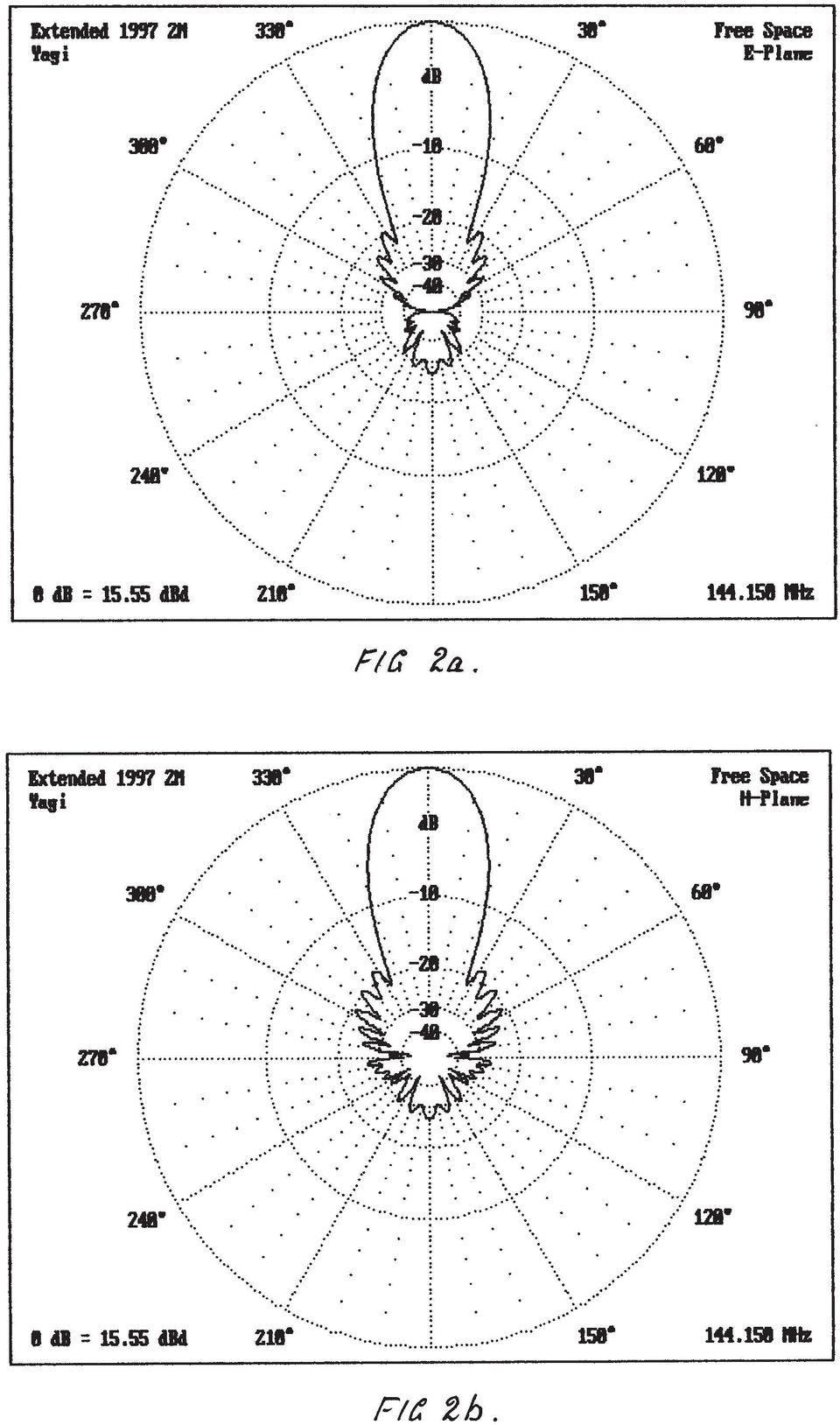
1 STACKING, PHASING and MATCHING YAGIS This is a synopsis of a talk presented to the Sydney VHF DX GROUP on Tuesday March 16th 1999 by Gordon McDonald VK2ZAB. QUESTIONS When the stacking of Yagis is being considered, the questions which usually arise are: 1. What are the reasons for stacking anyway? 2. Would building a bigger Yagi better suit our needs? 3. If we stack, what order of gain increase can we expect? 4. Is it better to stack vertically or horizontally? 5. How far apart do we stack the Yagis? 6. How do we manage the phasing requirements? 7. How do we manage the matching requirements? We will endeavour to answer these questions succinctly. WHY WE STACK We stack Yagis in order to increase the gain over that obtainable from one Yagi and/or to decrease the beamwidth. The increase in gain is due to the reduction in beamwidth and it should be noted that the beamwidth is reduced in the plane of stacking only. If we stack vertically the beamwidth is decreased in the vertical or H plane of a horizontally polarised Yagi. Stacking horizontally results in a narrower beamwidth in the horizontal or E plane of a horizontally polarised Yagi. In some applications, such as interference from or to points off to one side or below the main lobe, the reduction in beam width is a more important consideration than the gain increase. However most people stack to get more gain. CAN WE USE A BIGGER YAGI INSTEAD? Yes of course we can. The increase in gain due to stacking two Yagis approaches the limit of 3dB. We will see that this limit is overly optimistic in practice. Nevertheless, it is theoretically possible. So how much bigger would we have to make a Yagi in order to increase its gain by 3dB? If you think about it, the answer is obviously about twice as big. Consider Figs. 1a and 1b. This is a fairly big 2m Yagi with 13 elements on a six metre boom. It has a gain of 12.74dBd and a clean pattern. That is a pattern which has low side lobes in relation to the main lobe. Now look at Figs.2a and 2b. This is the same basic Yagi with its boom extended to twelve metres in length, elements added as required and the whole subjected to some optimisation adjustments to clean it up a bit. Note that it too has a clean pattern. Its gain of 15.55dBd is not quite a 3dB increase over the original, but close (2.81dB). So, would you put that up? That boom is 40 feet long. How is your rotator going to stand up to the extra torque when the westerlies hit it? How will the neighbours feel about it hanging over their backyard? No thanks! I would rather stack two of the six metre jobs. Still, the choice is yours. Someone may suggest that there are additional feeder losses in the stacked arrangement due to the need to connect the two Yagis together. This is true but there is also extra feeder loss due to the need to connect your feeder to the dipole which will be further out from the mast with the single Yagi. Not much in this argument..

2

3
4 HORIZONTAL OR VERTICAL STACK? What is your application? Do you think that it would be better to have a wide beam width in the H plane of your horizontally polarised antenna because you are into Meteor Scatter? Stack horizontally. Are you concerned that the power density due to your transmission is high in your neighbour s kitchen and that it would be better if you had a narrow beam in the H plane? Stack vertically. Is there a source of noise twenty degrees off to one side of your most used beam heading? Stack your horizontally polarised antennas horizontally. Are you interested in weak signals and simply want more gain? Stack four Yagis - two up and two across. Again, it s up to you. However, remember that horizontal supports near a horizontally polarised Yagi may give rise to destructive interaction. HOW FAR APART DO WE STACK? The old rule of thumb was to stack at two thirds of the boom length. This idea was presumably based on the aim of achieving a 3dB increase in gain over one Yagi. Look at Figs. 3a and 3b. This is the Yagi of Fig. 1 stacked at half and at two thirds the boom length. Note that at half the boom length large lobes have appeared on each side of the main lobe and 14dB down. These are called grating lobes and they are due to the pattern multiplication process so that they appear within the area of the main lobe of a single Yagi. The gain increase is 2.85dB. At two thirds the boom length the gain has increased to slightly more than 3dB over one Yagi according to the computer and the grating lobes have increased to less than 8dB down on the main lobe. If you had intended to reduce interference from or to some point off to one side or down from the main lobe this is obviously not going to help much. In fact the pattern has become very dirty. Digressing a bit: This idea of a 3dB increase in gain by stacking two Yagis is explained in some texts by invoking the concept of capture area It is explained that 3dB gain is obtained when the capture areas touch and do not overlap. However this idea does not lead to a stacking distance because, although the capture or effective area can be calculated by A = Gain x Wavelength / (4 x Pi), this does not define the shape of the area. There is no doubt that the capture or effective area idea is very useful in some other aspects of antenna engineering. It is dealt with at length by Klaus in his book Antennas. Returning to Fig. 3b. Note that the main beam width is half that of a single Yagi. This is where the 3dB gain increase comes from. The beam width in the nonstacked plane ( E plane in this case) has not changed.

5

6 Now look at Figs. 4a and 4b. This shows the pattern for the original Yagi stacked at 2.6 metres or 1.25 wavelengths. Note the clean pattern. No large grating lobes. The gain increase is slightly more than 2.5dB over a single Yagi. Most VHF DXers including moonbouncers now agree that this is the way to go. It has a better performance in terms of signal to noise ratio than an arrangement with more gain and a dirty pattern. So does this mean that we stack all our Yagis at 1.25 wavelengths apart? Certainly not. Remember that the grating lobes are within the area of the main lobe of the single Yagi. So if the single Yagi has a narrower beam to start with we can stack further apart without bringing up large grating lobes. Fig. 5. shows the 12m boom Yagi of Figs. 2a and 2b stacked at 4m or about two wavelengths RECOMMENDED STACKING DISTANCE. As we have seen this is related to the beamwidth of the Yagi you intend to stack. Joe Reisert W1JR reduced this relationship to a simple formula in his articles on Stacking Antennas in the April and May 1985 issues of Ham Radio. He says that, provided that your Yagi is clean to start with, which means that its side lobes are down more than 18dB on the main lobe, you should stack at a distance in wavelengths of 57 / 3dB beamwidth in degrees. This will give you a gain increase of more than about 2.8dB with grating lobes 13dB down on the main lobe. This is somewhat similar to Fig. 3a. I agree with the formula but I feel that grating lobes only 13dB down is not good enough so I recommend that, provided that your Yagi is clean to start with as defined above, you should stack at a distance in wavelengths of 52 / 3dB beamwidth in degrees. This will give you a gain increase of more than 2.5dB over a single Yagi and grating lobes which are better than 17dB down on the main lobe. How do you determine the 3dB beamwidth of your Yagi? If you are going to buy the Yagis look on the manufacturer s data sheet. If this is not supplied, don t buy the product. If you have the Yagi optimiser program YO5, which was used to produce the patterns of our Yagi examples, or YO6 which is an updated version you are in business. (These are supplied by Brian Beezley K6STI) If you intend to stack Yagis which you made from dimensions in a book, you will have to measure the beamwidth by rotating the Yagi while watching the signal level from a test oscillator or beacon. In this case it will be easier if you note the angle between the first nulls each side of the main lobe. The three db beamwidth is near enough to half this angle. Of course this only gives you the beamwidth in one plane - the E plane if you are horizontally polarised or the H plane if you are vertical. For Yagis with boomlengths of three wavelengths the E plane beamwidth is about 88% of the H plane beamwidth, if boom is 4 wavelengths E is about 89 % of H,if boom is 5 wavelengths E is about 91% of H and if boom is 6 wavelengths E is about 92% of H. This means that the recommended stacking distance is always greater for the E plane than it is for the H plane.

7

8 PHASING. There isn t much to this. It simply means that, looking at the stack as a receiving antenna, signals from all dipoles must be in phase at the feeder junction to the line to the shack. This in turn means that the left hand side of all dipoles in the array must be connected to the left hand side of all other dipoles in the array, that the feeders from each dipole must be the same length as the feeders from each other dipole connected to the same junction and that the feeders from any sub-junction must be the same length to the main junction as the feeders from any other subjunction. It also means that each Yagi must be mounted so that the distance from its phase reference point (the dipole) to a reference plane in front of the array is the same as that of all other Yagis in the array. Departures from these rules are possible for special applications outside the scope of this discussion. Refer to Fig. 6. MATCHING. There are two categories here. There are those who buy Yagis and those who build them. Those who buy almost invariably have Yagis with a coax lead attached providing a 50Ω unbalanced connection to each antenna. This limits the number of options available. Home brewers have an almost unlimited range of possible ways to hook up their stack.

9

10 Users of store bought Yagis. If you are in this category about the only thing you can do is to connect the individual Yagis to the common junction by means of quarter wave matching transformers of such impedance as to transform the 50Ω of each Yagi to that impedance which is equal to 50xN where N is the number of Yagis in the stack. Then, of course, the parallel impedance of the lot finishes at 50Ω again to match the line to the shack. The impedance of the matching transformers is found by the formula Z = sqrt(50x50n) where sqrt is square root. For twoyagis this is 70.71Ω, four Yagis 100Ω, six Yagis Ω and for eight Yagis Ω. These matching transformers are connected to the common connector providing the 50Ω input / output to the line to the shack in the form of two, four, six or eight leg power dividers. These are seldom available ready made but are not difficult to make. See Fig. 7. for the general idea.

11 The physical parameters of the air space coaxial matching sections are related to the required impedance by the formula Z = 138 log D/d where D is the inside diameter of the outer conductor and d is the diameter of the inner conductor. Home brewers of Yagis. There is virtually no limit to the options available and so it is impossible to cover everything. We will therefore limit ourselves to a few examples. For a start you could arrange the connections to your Yagi in the same manner as the store bought examples above and use power dividers in the same manner. However, home brewers can arrange to have any impedance they like at the terminals of their dipoles. This is particularly so if the highly recommended K6STI YO programs are available. You simply make a folded dipole of such impedance transformation ratio as will bring the straight dipole impedance of your Yagi up to the terminal impedance desired. A two conductor dipole with the two legs the same diameter multiplies the impedance by four times. A three conductor, same diameters, dipole multiplies by nine times and any other ratio may be fabricated using different conductor sizes for a two conductor dipole. A chart providing a straight line approximation of conductor sizes for different impedance ratios is in the ARRL Antenna Book. This freedom of choice facilitates the use of open wire interconnecting lines for your stack. The use of open wire lines is rarely recommended by Hams in the northern hemisphere because they have weather conditions which can cause the build up of ice and snow which changes the impedance and loss of the lines. We don t. All we have to worry about is water. Provided our lines are made so that the space between conductors is not closer than about 6mm or 1/4" there will be no problem with water bridging the lines. Properly made open wire lines have less loss than coax. They may be made of aluminium tubing with diameters of 9.5mm, 6.35mm or 4.7mm with few spacers so that they may also double as boom braces. The loss is related to the spacing which should not exceed about 1/12 of a wavelength. This means that they are practical up to the 23cm band. Practical line impedances are therefore between 300Ω and 150Ω minimum. In a stack of horizontally polarised Yagis, it is recommended that vertical runs of interconnecting lines be of the open wire sort. If this is done with aluminium tubing the lines are referred to as stacking bars. The relationship between the line impedance and the line dimensions is given by Z = 120 arc cosh(d/d) or approximately by Z = 276 log(2d/d) where D is the centre to centre spacing and d is the diameter of the lines. Home Brew Stack Examples. See Fig. 8a. This is a stack of two horizontally polarised Yagis. The dipoles are arranged to have terminal impedances of 100Ω each. This is transformed to 400Ω at the junction of stacking bars each 3/4 wavelength long and which may double as boom braces by having the central terminal block mounted on the mast. The two 400Ω in parallel give 200Ω which is connected to the down lead to the shack via a 4:1 coax balun of the trombone sort. If we want to stack four Yagis, two alongside two, we could use this arrangement and simply take the 50Ω coax from one vertical pair of Yagis to a central junction via a two leg power divider to meet the same length of 50Ω coax from the other vertical pair of Yagis.

12

13 See Fig 8b. This is a stack of four Yagis using a series / parallel connection which achieves flat lines, balance to unbalance conversion and minimum losses and uses 50Ω coax. It is a favourite of mine because it is a VK2ZAB original. The dipoles are arranged to have terminal impedances of 200Ω each. The Yagis in each vertically stacked pair are joined by 200Ω stacking bars of any length. The centre of the stacking bars is therefore 100Ω balanced. This point is connected to the 100Ω centre of the stacking bars of the other Yagi pair by 100Ω shielded transmission line in the form of the inners of two 50Ω coax lines of any length with their outers bonded together at convenient points such as the ends and junctions. Note that the left hand side of one set of stacking bars is connected to the fight hand side of the other set. These lines each have a T connection at points one quarter wavelength each side of the centre of the horizontal 50Ω coax lines, one to the right of centre, the other to the left. The impedance at each of these T connections is 25Ω to ground and the signals present are in phase and unbalanced to ground. We then join these two points to the downlead to the 50Ω down lead to the shack via a two leg power divider of 50Ω impedance which can of course be coaxial cable. The two 25Ω points are transformed to 100Ω each in parallel at the centre of the divider and so present 50Ω to the down lead connection. CONCLUSION Stacking Yagis provides gain and control over the radiation pattern more readily and with less mechanical strain than can be done with bigger Yagis. Do it! Author G.J.McDonald, VK2ZAB, 59 Wideview Road, Berowra Heights, NSW Australia. Phone/fax: (02) [email protected] Acknowledgements Richard Soulie VK2ARS for scanning the text and graphics Les Grant VK2KYJ for formatting and conversion to PDF

Selecting Receiving Antennas for Radio Tracking
 Selecting Receiving Antennas for Radio Tracking Larry B Kuechle, Advanced Telemetry Systems, Inc. Isanti, Minnesota 55040 [email protected] The receiving antenna is an integral part of any radio location
Coaxial Cable Feeder Influence on Yagi Antenna Dragoslav Dobričić, YU1AW [email protected]
 Coaxial Cable Feeder Influence on Yagi Antenna Dragoslav Dobričić, YU1AW [email protected] Introduction o far, in several previous articles [1, 2, 3], we investigated how boom radius and its S distance
5. ANTENNA TYPES. Figure 5. The vertical dipole and its electromagnetic equivalent, the vertical monopole
 Antennas can be classified in several ways. One way is the frequency band of operation. Others include physical structure and electrical/electromagnetic design. The antennas commonly used for LMR both
The VHF / UHF «Eggbeater» Antenna ~ Revisited ~
 The VHF / UHF «Eggbeater» Antenna ~ Revisited ~ ON6WG / F5VIF A new simple way to build the Eggbeater Antenna Introduction Previous designs described in «VHF / UHF «Eggbeater» Antenna ~ Part 1» and «VHF
Just a Dipole. Gary Wescom N0GW July 16, 2007
 Just a Dipole Gary Wescom N0GW July 16, 2007 Often we will hear people describing their antennas as just a dipole. After all, a coax cable fed, half wavelength dipole is one of the simplest antennas to
Antenna Deployment Technical Brief
 ProCurve Networking Antenna Deployment Technical Brief Introduction... 2 Antenna types... 2 Omni directional antennas... 2 Directional antennas... 2 Diversity antennas... 3 High gain directional antennas...
HUMAN EXPOSURE TO EMR: ASSESSMENT OF AMATEUR RADIO STATIONS FOR COMPLIANCE WITH ACA REQUIREMENTS
 HUMAN EXPOSURE TO EMR: ASSESSMENT OF AMATEUR RADIO STATIONS FOR COMPLIANCE WITH ACA REQUIREMENTS May 2005 Version 2.0 PO Box 78 BELCONNEN ACT 2616 Telephone (02) 6219 5555 Facsimile (02) 6219 5353 www.aca.gov.au
Designing Log Periodic Antennas
 Designing Log Periodic Antennas By Glen Dash, Ampyx LLC, GlenDash at alum.mit.edu Copyright 2000, 2005 Ampyx LLC Lightweight and precise, the log periodic has become a favorite among EMC engineers. In
Antennas 101 The Basics. Ward Silver NØAX
 Antennas 101 The Basics Ward Silver NØAX The Basics - 1 Antennas radiate (or receive) because electrons are accelerated (or are caused to accelerate) in the antenna s elements Radio or electromagnetic
40m-10m DELTA LOOP ANTENNA - GU3WHN
 This simple broad band antenna is easy to build, has gain similar to that of a dipole and is tolerant of nearby objects. It can be erected in almost any configuration provided the wires are well separated
Weekend Antennas No. 1 A Bobtail Curtain for 2m
 Weekend Antennas No. 1 A Bobtail Curtain for 2m Welcome to the first installment of my new column, which I hope will become a regular feature in Radio ZS. Each installment will present a practical and
Antenna Glossary Before we talk about specific antennas, there are a few common terms that must be defined and explained:
 Antenna Basics Introduction Antennas are a very important component of communication systems. By definition, an antenna is a device used to transform an RF signal, traveling on a conductor, into an electromagnetic
LDG RBA-4:1Balun LDG RBA-1:1Balun
 LDG RBA-4:1Balun LDG RBA-1:1Balun Table of Contents Features 1 Specifications 1 Preparation 2 An important word about power levels: 2 Installation 2 Care and Maintenance 6 Technical Support 6 Warranty
Design of a Planar Omnidirectional Antenna for Wireless Applications
 Design of a Planar Omnidirectional Antenna for Wireless Applications Randy Bancroft and Blaine Bateman Centurion Wireless Technologies Westminster, Colorado Abstract Omnidirectional antennas are of great
VE3MLB Phased Double V Antenna for 75/80 Meter Band
 Jan. 17, 2008 VE3MLB Phased Double V Antenna for 75/80 Meter Band This is a story of a double inverted V antenna that I built in January 2008. I already had a full 80 meter Delta loop suspended from my
This Antenna Basics reference guide includes basic information about antenna types, how antennas work, gain, and some installation examples.
 Antenna Basics This Antenna Basics reference guide includes basic information about antenna types, how antennas work, gain, and some installation examples. What Do Antennas Do? Antennas transmit radio
Understanding Range for RF Devices
 Understanding Range for RF Devices October 2012 White Paper Understanding how environmental factors can affect range is one of the key aspects to deploying a radio frequency (RF) solution. This paper will
Modeling an 80/40/20M Fan Dipole for DX
 Modeling an 80/40/20M Fan Dipole for DX New Station New Antennas! Installation and SWR Response Where is the DX? How do these Dipoles Play? (EZNEC) What about Terrain? HFTA and Terrain The effect on these
Antenna Basic Concepts
 ANTENNA An antenna is a device to transmit and/or receive electromagnetic waves. Electromagnetic waves are often referred to as radio waves. Most antennas are resonant devices, which operate efficiently
The spiderbeam was developed as a DXpeditioner's dream antenna. It is a full size lightweight tribander yagi made of fiberglass and wire.
 The spiderbeam was developed as a DXpeditioner's dream antenna. It is a full size lightweight tribander yagi made of fiberglass and wire. The whole antenna weight is only kg (lbs), making it ideally suited
Pillbox Antenna for 5.6 GHz Band Dragoslav Dobričić, YU1AW [email protected]
 Pillbox Antenna for 5.6 GHz Band Dragoslav Dobričić, YU1AW [email protected] Introduction The pillbox or cheese antenna is made of two parallel plates which are connected to the narrow strip of parabolic
Sensor and Simulation Notes. Note 479. October 2003. A Dual-Polarity Impulse Radiating Antenna
 Sensor and Simulation Notes Note 479 October 2003 A Dual-Polarity Impulse Radiating Antenna Leland H. Bowen and Everett G. Farr Farr Research, Inc. Dean I. Lawry Air Force Research Laboratory, Directed
JP Tribander Owner Manual
 JP Tribander Owner Manual JP-Tribander Technical overview JP-Tribander is effective tribander beam for 20m, 15m and 10meters with full size elements without traps. Antenna is designed using latest computer
Cheap Antennas for the AMSAT LEO's Kent Britain -- WA5VJB
 Cheap Antennas for the AMSAT LEO's Kent Britain -- WA5VJB Cheap LEO Antenna Drew, KO4MA, using the Cheap LEO antenna during a Dayton AMSAT LEO Demonstration Hand held dual band antennas are popular for
Understanding SWR by Example
 Understanding SWR by Example Take the mystery and mystique out of standing wave ratio. Darrin Walraven, K5DVW It sometimes seems that one of the most mysterious creatures in the world of Amateur Radio
ISS Minimalist Antenna
 ISS Minimalist Antenna The purpose of this project was to develop an antenna suggestion that would allow for a simple to duplicate, affordable antenna solution for reasonable access to signals transmitted
2 Meter Half-Wave J-Pole Antenna From 450 Ohm Ladder Line
 2 Meter Half-Wave J-Pole Antenna From 450 Ohm Ladder Line Photos: Copyright 2007 David Jordan WA3GIN. All rights reserved. This is a good rainy day antenna project for those of you who would like to home
Technician Licensing Class
 Technician Licensing Class Antennas Presented by Amateur Radio Technician Class Element 2 Course Presentation ELEMENT 2 SUB-ELEMENTS (Groupings) About Ham Radio Call Signs Control Mind the Rules Tech Frequencies
Connecting Your Receiver to the Antenna
 TECHNOTE No. 3 Joe Carr's Radio Tech-Notes Connecting Your Receiver to the Antenna Joseph J. Carr Universal Radio, Inc. 6830 Americana Parkway Reynoldsburg, Ohio 43068 1 Connecting Your Receiver to the
Avaya WLAN 9100 External Antennas for use with the WAO-9122 Access Point
 Avaya WLAN 9100 External Antennas for use with the WAO-9122 Access Point Overview To optimize the overall performance of a WLAN in an outdoor deployment it is important to understand how to maximize coverage
The Gamma Match. 1 Equal Size Elements
 The Gamma Match The gamma match was originally invented as a means of feeding vertical monopole antennas for medium wave broadcasts, which were earthed at the base for lightning protection (see Figure
Antenna Trainer EAN. www.edibon.com. Technical Teaching Equipment INTRODUCTION
 Antenna Trainer EAN Technical Teaching Equipment Products Products range Units 3.-Communications INTRODUCTION Antennas are the main element of aerial communications. They are the transition between a transmission
Antenna Properties and their impact on Wireless System Performance. Dr. Steven R. Best. Cushcraft Corporation 48 Perimeter Road Manchester, NH 03013
 Antenna Properties and their impact on Wireless System Performance Dr. Steven R. Best Cushcraft Corporation 48 Perimeter Road Manchester, NH 03013 Phone (603) 627-7877 FAX: (603) 627-1764 Email: [email protected]
Analysis of the G3LTF Dual Band Feed for 23cm and 13cm Paul Wade W1GHZ 2004 [email protected]
 Analysis of the G3LTF Dual Band Feed for 23cm and 13cm Paul Wade W1GHZ 2004 [email protected] In the March 2004 edition of the RSGB Microwave Newsletter, G3LTF described 1 a dual band feed for the 23 cm and
A Broadband Hexbeam. Steve Hunt, G3TXQ
 A Broadband Hexbeam Steve Hunt, G3TXQ Introduction Ilike the Hexbeam. Anyone who wants an HF antenna that can be multi-banded, exhibits useful gain and directivity, is lightweight, has a small turning
The Antenna Balun. What is this thing and why do I need it?
 What is this thing and why do I need it? The Antenna Balun In this chapter we will look at a common component in some transmission systems the balun. It is quite common to see a balun in wire antennas
Efficient 2 meter Disguise Antenna Made From a TV Satellite Dish
 Efficient 2 meter Disguise Antenna Made From a TV Satellite Dish This horizontal slot antenna, cut into the reflector of a TV dish, is both the master of disguise and high in performance. By John Portune
Mobile use, radio signals and health
 Mobile use, radio signals and health Mobile use, radio signals and health How does the mobile network work? Since the 1970s, the use of various types of radio transmitters has risen dramatically, to the
You will need the following pieces of equipment to complete this experiment:
 UNIVERSITY OF TORONTO FACULTY OF APPLIED SCIENCE AND ENGINEERING The Edward S. Rogers Sr. Department of Electrical and Computer Engineering ECE422H1S: RADIO AND MICROWAVE WIRELESS SYSTEMS EXPERIMENT 3:
Antennas, Masts, Head amplifiers, Cables and Filters for a 143.050MHz Meteor Scatter Radar Receiver
 1 Introduction This article describes some options for amateur radio astronomers who wish to construct a practical, low cost receiver station to observe meteor scatter echoes from the French Graves space
WAVEGUIDE-COAXIAL LINE TRANSITIONS
 WAVEGUIDE-COAXIAL LINE TRANSITIONS 1. Overview Equipment at microwave frequencies is usually based on a combination of PCB and waveguide components. Filters and antennas often use waveguide techniques,
EH-20 20m antenna. By VE3RGW
 EH-20 20m antenna By VE3RGW Equivalent circuit of EH-20 (prototype 2A) antenna system. Upper cylinder Lower cylinder Ground Counter pose Phasing coil Impedance transformer and tune circuit Tune coil Feed
M2 Antenna Systems, Inc. Model No: KT34M2
 M2 Antenna Systems, Inc. Model No: KT34M2 10m f, MHz G, dbi F/B, db 28.0 7.3 18 28.2 7.3 23 28.4 7.4 25 28.6 7.5 24 29.2 7.6 20 15m f, MHz G, dbi F/B, db 21.0 6.9 19 21.1 6.9 22 21.2 7.0 24 21.3 7.0 24
Amplifier for Small Magnetic and Electric Wideband Receiving Antennas (model AAA-1B)
") Amplifier for Small Magnetic and Electric Wideband Receiving Antennas (model AAA-1B) 1. Description and Specifications Contents 1.1 Description 1.2 1.2 Specifications 1.3 1.3 Tested parameters in production
Amplifier for Small Magnetic and Electric Wideband Receiving Antennas (model AAA-1B) 1. Description and Specifications Contents 1.1 Description 1.2 1.2 Specifications 1.3 1.3 Tested parameters in production
Shielding Effectiveness Test Method. Harbour s LL, SB, and SS Coaxial Cables. Designs for Improved Shielding Effectiveness
 Shielding Effectiveness Test Method Harbour s LL, SB, and SS Coaxial Cables Designs for Improved Shielding Effectiveness Harbour Industries 4744 Shelburne Road Shelburne Vermont 05482 USA 802-985-3311
EE302 Lesson 14: Antennas
 EE302 Lesson 14: Antennas Loaded antennas /4 antennas are desirable because their impedance is purely resistive. At low frequencies, full /4 antennas are sometime impractical (especially in mobile applications).
Omni Antenna vs. Directional Antenna
 Omni Antenna vs. Directional Antenna Document ID: 82068 Contents Introduction Prerequisites Requirements Components Used Conventions Basic Definitions and Antenna Concepts Indoor Effects Omni Antenna Pros
Digital Active Indoor Antenna SRT ANT 10 ECO
 Digital Active Indoor Antenna SRT ANT 10 ECO Picture similar User Manual Table of contents 1.0 INTRODUCTION 1 2.0 PACKAGE CONTENT 1 3.0 SAFETY NOTES 2 4.0 CONNECTING THE ANTENNA 2 1.0 INTRODUCTION Thank
An octave bandwidth dipole antenna
 An octave bandwidth dipole antenna Abstract: Achieving wideband performance from resonant structures is challenging because their radiation properties and impedance characteristics are usually sensitive
Applications in EMC testing. Outline. Antennas for EMC Testing. Terminology
 Antennas for EMC Testing Zhong Chen ETS-Lindgren 1301 Arrow Point Drive Cedar Park, TX 78613 [email protected] Outline EMC Terms and Definitions Typical EMC Antennas Calibration of EMC Antennas
Small HF Antennas - - -- - - - -- - - ! The Small Space and Big Antenna Dilemma! Constraints
 Small HF Antennas! The Small Space and Big Antenna Dilemma! Constraints " Covenants " Restricted lot size " City Bylaws " Boards of Variance " Strata Rules " Neighbor complaints of unsightly structures
'' EGGBEATER '' ANTENNA VHF/UHF ~ PART 2
 '' EGGBEATER '' ANTENNA VHF/UHF ~ PART 2 ON6WG / F5VIF Summary Note : In Part 1, Fig 1 shows a maximum gain of 6.45 dbi. Several design attempts were made using slightly different configurations ( i.e.
Sound absorption and acoustic surface impedance
 Sound absorption and acoustic surface impedance CHRISTER HEED SD2165 Stockholm October 2008 Marcus Wallenberg Laboratoriet för Ljud- och Vibrationsforskning Sound absorption and acoustic surface impedance
Rec. ITU-R F.699-5 1 RECOMMENDATION ITU-R F.699-5 *
 Rec. ITU-R F.699-5 1 RECOMMENATION ITU-R F.699-5 * REFERENCE RAIATION PATTERNS FOR LINE-OF-SIGHT RAIO-RELAY SYSTEM ANTENNAS FOR USE IN COORINATION STUIES AN INTERFERENCE ASSESSMENT IN THE FREQUENCY RANGE
2m and 70cm Portable Beam for ARES
 The Amateur Radio Emergency Services (ARES) is a group of licensed amateurs who volunteer their time and equipment for communications activity in support of public service agencies. ARES trains with the
Modeling and Measuring the Creative Design CLP5130-2N Log Periodic Antenna
 Modeling and Measuring the Creative Design CLP5130-2N Log Periodic Antenna Whitham D. Reeve 1. Introduction A log periodic antenna is an array of dipoles with mathematically related lengths and spacings.
Cellular Wireless Antennas
 Cellular Wireless Antennas A Technical Brief GarrettCom Inc., November 2010 Overview The Cellular Wireless Antenna Technical brief is provided to assist with the design and deployment of the DX940 Cellular
Newcomers and Elmers Net: More Wire Antennas 02.14.16 Robert AK3Q
 Newcomers and Elmers Net: More Wire Antennas 02.14.16 Robert AK3Q Antenna Construction Supplies Antenna Construction Tools (Harbor Freight can be a good place to go) Wire Cutters; Pliers (regular and needle
THE OCF FD4 (FD3) WINDOM ANTENNA
 WINDOM ANTENNA") THE OCF FD4 (FD3) WINDOM ANTENNA FD4 (80/40/20/10 m) The 4-band Fritzel model FD4 is a special version of a Windom antenna. It is a half-wave long on the lowest frequency, and is fed from a coax cable
THE OCF FD4 (FD3) WINDOM ANTENNA FD4 (80/40/20/10 m) The 4-band Fritzel model FD4 is a special version of a Windom antenna. It is a half-wave long on the lowest frequency, and is fed from a coax cable
The W5JCK Guide to the Mathematic Equations Required for the Amateur Extra Class Exam
 The W5JCK Guide to the Mathematic Equations Required for the Amateur Extra Class Exam This document contains every question from the Extra Class (Element 4) Question Pool* that requires one or more mathematical
INVESTIGATION, DESIGN, CONSTRUCTION AND TESTING BROADBAND ANTENNA FOR RADIO TELESCOPE ARRAY RECEIVER
 INVESTIGATION, DESIGN, CONSTRUCTION AND TESTING BROADBAND ANTENNA FOR RADIO TELESCOPE ARRAY RECEIVER PREPARED BY: ONKGOPOTSE ISAAC MADIKWANE UNIVERSITY OF CAPE TOWN DEPARTMENT OF ELECTRICAL ENGINEERING
Invisible DX Antenna for the Low Bands
 Invisible DX Antenna for the Low Bands By Heinz-Josef Pick, DK5WL Summary This paper describes a multi-band DX antenna for the 160m-40m amateur radio bands with low visibility but great performance for
Basic Wire Antennas. Part II: Loops and Verticals
 Basic Wire Antennas Part II: Loops and Verticals A loop antenna is composed of a single loop of wire, greater than a half wavelength long. The loop does not have to be any particular shape. RF power can
Antennas & Propagation. CS 6710 Spring 2010 Rajmohan Rajaraman
 Antennas & Propagation CS 6710 Spring 2010 Rajmohan Rajaraman Introduction An antenna is an electrical conductor or system of conductors o Transmission - radiates electromagnetic energy into space o Reception
4 SENSORS. Example. A force of 1 N is exerted on a PZT5A disc of diameter 10 mm and thickness 1 mm. The resulting mechanical stress is:
 4 SENSORS The modern technical world demands the availability of sensors to measure and convert a variety of physical quantities into electrical signals. These signals can then be fed into data processing
MD5-26 Stacking Blocks Pages 115 116
 MD5-26 Stacking Blocks Pages 115 116 STANDARDS 5.MD.C.4 Goals Students will find the number of cubes in a rectangular stack and develop the formula length width height for the number of cubes in a stack.
GAP CLOSING. Volume and Surface Area. Intermediate / Senior Student Book
 GAP CLOSING Volume and Surface Area Intermediate / Senior Student Book Volume and Surface Area Diagnostic...3 Volumes of Prisms...6 Volumes of Cylinders...13 Surface Areas of Prisms and Cylinders...18
ANTENNER och TILLBEHÖR
 ANTENNER och TILLBEHÖR Antenner Fästen Monteringstillbehör Kablar Kontakter SPARK / DB / 6 ANTENNA TYPE VHF fiberglass antenna incl. 5 mtr RG-58 and 1 pc PL-259 connector FREQUENCY 156-162 MHz IMPEDANCE
Dummies guide to aircraft antennas
 Dummies guide to aircraft antennas Probably the single biggest issue that we encounter with the installation of our XCOM radios by customers in the field is poor antenna performance. Most customers are
Antenna Patterns and Their Meaning
 Antenna Patterns and Their Meaning Much can be learned about how an antenna performs from its patterns. This paper describes many of the common antenna parameters that can be understood from the patterns.
Digital Systems Ribbon Cables I CMPE 650. Ribbon Cables A ribbon cable is any cable having multiple conductors bound together in a flat, wide strip.
 Ribbon Cables A ribbon cable is any cable having multiple conductors bound together in a flat, wide strip. Each dielectric configuration has different high-frequency characteristics. All configurations
Physics 3330 Experiment #2 Fall 1999. DC techniques, dividers, and bridges R 2 =(1-S)R P R 1 =SR P. R P =10kΩ 10-turn pot.
R P R 1 =SR P. R P =10kΩ 10-turn pot.") Physics 3330 Experiment #2 Fall 1999 DC techniques, dividers, and bridges Purpose You will gain a familiarity with the circuit board and work with a variety of DC techniques, including voltage dividers,
Physics 3330 Experiment #2 Fall 1999 DC techniques, dividers, and bridges Purpose You will gain a familiarity with the circuit board and work with a variety of DC techniques, including voltage dividers,
Siemens Energy & Automation. structured. WIRING Product Training Series: Advanced Video Session 3
 s structured WIRING Product Training Series: Advanced Video Session 3 1 Table of Contents This presentation will give you a closer look at Video in Structured Wiring applications. The following Areas will
EMC STANDARDS STANDARDS AND STANDARD MAKING BODIES. International. International Electrotechnical Commission (IEC) http://www.iec.
 http://www.iec.") EMC STANDARDS The EMC standards that a particular electronic product must meet depend on the product application (commercial or military) and the country in which the product is to be used. These EMC regulatory
EMC STANDARDS The EMC standards that a particular electronic product must meet depend on the product application (commercial or military) and the country in which the product is to be used. These EMC regulatory
Pole Lathe and Shave Horse Design
 Pole Lathe and Shave Horse Design These pictures and accompanying words are Copyright Michael Hughes February 2002. They are not to be re-produced, in part or whole, without permission from the author.
Marine HF SSB Installation and Grounding. Anatomy of the Best Tour 2006
 Marine HF SSB Installation and Grounding Anatomy of the Best Tour 2006 Marine HF Installation Considerations This document is meant to be an overview of Marine HF radio installation For detailed installation
"EGGBEATER"ANTENNA VHF/UHF ~ PART 1
 "EGGBEATER"ANTENNA VHF/UHF ~ PART 1 ON6WG / F5VIF For the enthusiastic listeners or the licensed amateur station wishing to experiment with satellite transmissions without investing a large sum of money
x x y y Then, my slope is =. Notice, if we use the slope formula, we ll get the same thing: m =
 Slope and Lines The slope of a line is a ratio that measures the incline of the line. As a result, the smaller the incline, the closer the slope is to zero and the steeper the incline, the farther the
Lesson 26: Reflection & Mirror Diagrams
 Lesson 26: Reflection & Mirror Diagrams The Law of Reflection There is nothing really mysterious about reflection, but some people try to make it more difficult than it really is. All EMR will reflect
impedance is easier for the tuner to cope with across multiple bands which are related to even harmonic lengths of the dipole.
 By Ron Bertrand VK2DQ - 2007 Want to build a simple, efficient, multiband antenna? One of the best and inexpensive multiband antennas is the off-centre-fed (OCF) dipole. These are wonderfully simple antennas
HAM RADIO VHF/UHF MOBILE INSTALLATION
 do s - and a few don ts HAM RADIO VHF/UHF MOBILE INSTALLATION by Mike Baker, W8CM Three categories: 1. DC power 2. Antenna 3. Radio INSTALLING THE DC POWER IS LOTS OF FUN INSTALLING THE DC POWER IS LOTS
Electromagnetic radiation exposure: assessment against ACA mandated limits
 Electromagnetic radiation exposure: assessment against ACA mandated limits General radio services (operating above 0 MHz) (Edition May 0) Disclaimer Unless otherwise specified, the information contained
Electromagnetic radiation exposure: assessment against ACA mandated limits
 Electromagnetic radiation exposure: assessment against ACA mandated limits Paging services (Edition May 2002) Disclaimer Unless otherwise specified, the information contained in these guidelines is intended
Boom Influence on Yagi Antenna Dragoslav Dobričić, YU1AW (Serbia) [email protected]
 dragan@antennex.com") Boom Influence on Yagi Antenna Dragoslav Dobričić, YU1AW (Serbia) [email protected] Introduction T he boom of the Yagi antenna is an inevitable part of its construction. Theoretically, Yagi antennas
Boom Influence on Yagi Antenna Dragoslav Dobričić, YU1AW (Serbia) [email protected] Introduction T he boom of the Yagi antenna is an inevitable part of its construction. Theoretically, Yagi antennas
PLEASE - Read this entire booklet and study the diagrams before building a Quad, it can save you unwarranted frustrations!
 VHF/UHF Quad Antenna The information in this article has come from many amateur sources, the most notable was from WA6TEY (sk 1985) Ray Frost, who was a pioneer of VHF Quad designs and one of the best
Encoded Phased Array Bridge Pin Inspection
 Encoded Phased Array Bridge Pin Inspection James S. Doyle Baker Testing Services, Inc. 22 Reservoir Park Dr. Rockland, MA 02370 (781) 871-4458; fax (781) 871-0123; e-mail [email protected] Product
Algebra: Real World Applications and Problems
 Algebra: Real World Applications and Problems Algebra is boring. Right? Hopefully not. Algebra has no applications in the real world. Wrong. Absolutely wrong. I hope to show this in the following document.
Receiving Saorview Digital Terrestrial Television
 Receiving Saorview Digital Terrestrial Television Introduction RTÉ NL Nutley Building Donnybrook Dublin 4 Tel: 01-2082223 Fax: 01-2082283 Email: [email protected] Web: www.rtenl.ie Saorview s Digital Terrestrial
THE IMPOSSIBLE DOSE HOW CAN SOMETHING SIMPLE BE SO COMPLEX? Lars Hode
 THE IMPOSSIBLE DOSE HOW CAN SOMETHING SIMPLE BE SO COMPLEX? Lars Hode Swedish Laser-Medical Society The dose is the most important parameter in laser phototherapy. At a first glance, the dose seem very
AS COMPETITION PAPER 2008
 AS COMPETITION PAPER 28 Name School Town & County Total Mark/5 Time Allowed: One hour Attempt as many questions as you can. Write your answers on this question paper. Marks allocated for each question
Electrical Resonance
 Electrical Resonance (R-L-C series circuit) APPARATUS 1. R-L-C Circuit board 2. Signal generator 3. Oscilloscope Tektronix TDS1002 with two sets of leads (see Introduction to the Oscilloscope ) INTRODUCTION
Geometry Notes PERIMETER AND AREA
 Perimeter and Area Page 1 of 57 PERIMETER AND AREA Objectives: After completing this section, you should be able to do the following: Calculate the area of given geometric figures. Calculate the perimeter
SUSP-06, Torsion Bars - Removing, Replacing, and Indexing
 Introduction SUSP-06, Torsion Bars - Removing, Replacing, and Indexing Replacing the torsion bar on a 944 is not all that difficult. However, reindexing the torsion after completion is a pain and can be
Video Camera Installation Guide
 Video Camera Installation Guide The intent of this guide is to provide the information needed to complete or modify a video camera installation to avoid lightning and induced power surge damage. This guide
30 minutes in class, 2 hours to make the first time
 Asking questions and defining problems Developing and using models Planning and carrying out investigations 30 minutes in class, 2 hours to make the first time 3 12 x 24 x ¾ inch plywood boards 1 x 12
antennex Issue No. 122 June 2007 Page 1
 High Performance Cubical Quad Antennas 3 rd Edition by John Koszeghy, K3BB: a Review L. B. Cebik, W4RNL John Koszeghy, K3BB (ex-k2ob) has had a love affair with quad beams for 45 years. Indeed, he subtitles
OPERATING P L AYA B I L I T Y P R E C I S I O N D E S I G N
 P L AYA B I L I T Y P R E C I S I O N P E R F O R M A N C E OPERATING INSTRUCTIONS FOR: GolfWorks Loft and Lie Gauges code: HGCG/DGCG/LOLI2 4820 Jacksontown Road P.O. Box 3008 Newark, Ohio 43058-3008 Toll-Free:
Embedded FM/TV Antenna System
 1 Embedded FM/TV Antenna System Final Report Prepared for By January 21, 2011 2 Table of Contents 1 Introduction... 5 2 Technical Specification... 6 3 Prototype Antenna... 7 4 FASTROAD Active module fabrication...
Franz Hirtenfelder and Stephen Murray, CST Computer Simulation Technology and W. L. Gore and Associates (Gore) March 5, 2015
 March 5, 2015") 1 of 7 3/17/2015 9:38 AM Home Franz Hirtenfelder and Stephen Murray, CST Computer Simulation Technology and W. L. Gore and Associates (Gore) March 5, 2015 Editor s Note: A cable that leaks electromagnetic
1 of 7 3/17/2015 9:38 AM Home Franz Hirtenfelder and Stephen Murray, CST Computer Simulation Technology and W. L. Gore and Associates (Gore) March 5, 2015 Editor s Note: A cable that leaks electromagnetic
Grade 7/8 Math Circles November 3/4, 2015. M.C. Escher and Tessellations
 Faculty of Mathematics Waterloo, Ontario N2L 3G1 Centre for Education in Mathematics and Computing Tiling the Plane Grade 7/8 Math Circles November 3/4, 2015 M.C. Escher and Tessellations Do the following