KOBOLD VKP FLOWMETER/SWITCH. User Instructions
|
|
|
- Morris Matthews
- 9 years ago
- Views:
Transcription
1 KOBOLD VKP FLOWMETER/SWITCH User Instructions USA 1801 Parkway View Drive Pittsburgh, PA PH Canada 9A Aviation Point Claire, QC H9R 4Z2 PH Manual_VKP_

2 VKP Table of Contents 1.0 General Specifications Principle of Operation Installation Instructions Mounting Use of Set Point Contact Connecting to the Contact Contact Protection Arrival of Damaged Equipment Need help with your VKP? List Of Diagrams Diagram 2.3 Dimensions Diagram 2.4 Wiring of the Reed Switch Diagram 2.6 Contact Protection List of Tables Table 2.1 Material Composition Table 2.2 Operational Limits Table 2.5 Electrical Data and Operational Limits

3 1 VKP KOBOLD VKP FLOWMETER User Instructions CAUTION: For safety reasons, please read the cautionary information located at the end of the manual, before attempting installation. 1.0 General The KOBOLD VKP is a partially viscosity compensated flowmeter, scaled to be read directly with use of water or oil with a viscosity of 100 cst based on model number. This partial compensation is achieved through the use of a spring in conjunction with our patented knife-edge orifice in the float. Since part of the medium flows past the periphery of the float, full compensation is unobtainable. The basic theory of operation is that of the well-known float in a conical tube. The conical shape is obtained through use of an inverted cone in the base of the instrument - the guide tube is cylindrical. The construction, being plastic, is such that fluids flow between the float and guide cylinder wall. This makes full viscosity compensation impossible. The advantage of this, however, is that by increasing the float-cylinder tolerance, dirty fluids may be passed through the special version of the instrument, the VKP-6 (particles up to 400µ in diameter).

4 VKP Specifications Table 2.1; Material Composition Standard Options Housing Polysulfone - Float Polysulfone - Spring 301 SS - Retaining Ring PH 15-7 MO - 1/2 and 3/4 connections Nut - Brass or SS Internal Parts - Brass or SS Seal - NBR Seals VKP Klingerit-Oilit Table 2.2; Operational Limits Viscosity Range: Maximum Medium Temperature: Maximum Internal Pressure: v = cst (mm²/s) 250 F 230 PSIG

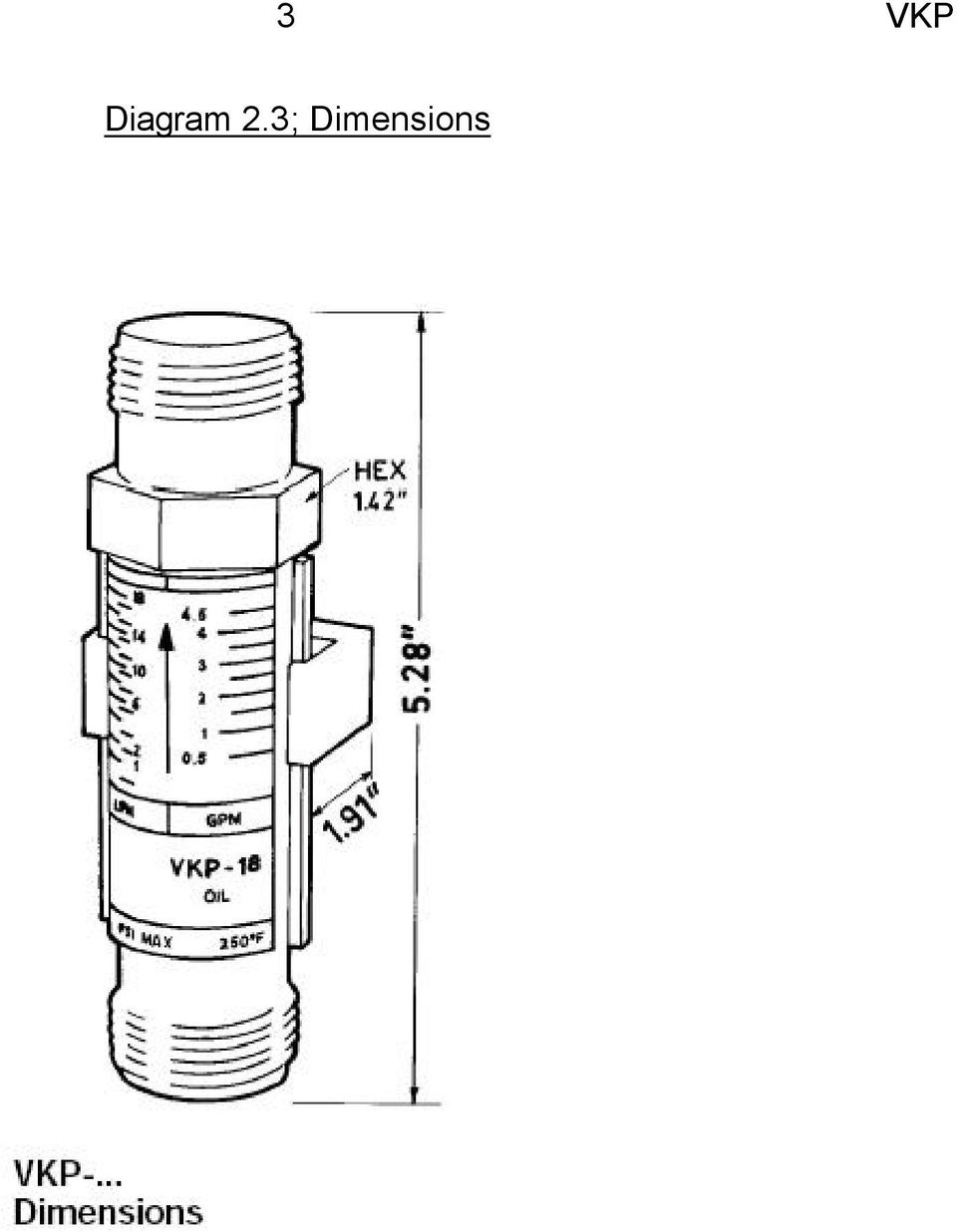
5 3 VKP Diagram 2.3; Dimensions
6 VKP 4 Diagram 2.4; Wiring of Reed Switch N/O Contact, Bi-stable Table 2.5; Electrical Data and Operational Limits Maximum Voltage: Maximum Current: Maximum Power Dissipation: 200 V 0.5 A 10 Watts Environmental Protection: IP 65 (IEC 259)

7 5 VKP 3.0 Principle of Operation The KOBOLD VKP flowmeter has a spring-loaded float which slides within a cylindrical measuring tube. Our patented process for achieving viscosity compensation hinges on the use of the nonlinear behavior of the float spring in combination with a unique orifice integral to the float itself. A large amount of medium density compensation is provided simultaneously. Should flow monitoring be desired, limit switches may be added to the device easily. Permanent magnets on the float actuate an electrically isolated, sealed contact (reed switch) mounted on the outside of the instrument housing. This arrangement guarantees hermetic separation of the medium and the electrical system. The contact is embedded within a plastic housing to prevent damage to the contacts by mechanical action or aggressive atmospheres. The contact housing is mounted in slides to enable set point changes to be effected. The flowing media raises the float against the spring force. When the magnetic field reaches the contact reeds of the reed switch, the contact actuates. As the flow increases, the float rises until it reaches its stop. This prevents the float from going beyond the contact range of the magnetic switch, i.e., the contact remains activated. The result is bistable switching without a latching relay as normally required. 4.0 Installation Instructions CAUTION: For safety reasons, please read the cautionary information located at the end of the manual, before attempting installation Mounting 1. The VKP may be mounted in any orientation without affecting accuracy. 2. The medium must flow through the instrument in the direction indicated by the arrow on the housing. 3. The medium must not contain any solids which would interfere with proper operation of the device. It is advisable to provide filters with built-in magnetic separators upstream of the VKP. (KOBOLD s MFR filters or equivalent will suffice.) 4. Make mechanical connections according to the directions in the cautionary statement located at the end of this manual.
 mounted on the outside of the instrument housing.")
8 VKP Use of Set Point Contact If you choose a device with option "-R", your VKP is equipped with a bistable reed contact. The position of this contact is adjusted by sliding the switch housing (white rectangular structure) up and down the slide rails on the side of your unit. The contact is engaged by a magnet in the float. This means that there is a given amount of hysteresis built into the switching function, resulting in different turn-on and turn-off points Connecting to the Contact Connect wiring between Terminals 1 and 2 as shown in Diagram 2.4 (page 4). Do not install the meter in areas where strong electric fields are present, as this will hamper proper operation of the reed contact.

9 7 VKP Contact Protection Maximum values of current and voltage must not be exceeded on the reed contact. When driving inductive or capacitive loads, we recommend protecting the contact as diagrammed below. If continuous load values exceed contact rating, we recommend the use of an isolation relay. KOBOLD provides a line of relays for such instances. Diagram 2.6; Contact Protection 5.0 Arrival of Damaged Equipment Your instrument was inspected prior to shipment and found to be defect-free. If damage is visible on the unit, we advise that you carefully inspect the packing in which it was delivered. If damage is visible, notify your local carrier at once, since the carrier is liable for a replacement under these circumstances. If your claim is refused, please contact KOBOLD Instruments for further advisement. 6.0 Need help with your VKP? Call one of our friendly engineers at

10 9 VKP Caution PLEASE READ THE FOLLOWING GENERAL FLOW METER/ MONITOR WARNINGS BEFORE ATTEMPTING INSTALLATION OF YOUR NEW DEVICE. FAILURE TO HEED THE INFORMATION HEREIN MAY RESULT IN EQUIPMENT FAILURE AND POSSIBLE SUBSEQUENT PERSONAL INJURY.

11 11 VKP KOBOLD manufactures a wide range of process sensors and technologies. While each of these technologies are designed to operate in a wide variety of applications, it is the user's responsibility to select a technology that is appropriate for the application, to install it properly, to perform tests of the installed system, and to maintain all components. The failure to do so could result in property damage or serious injury. Inspect instrument for damage upon arrival. Cracked, fractured, bent or otherwise damaged instruments must not be put into use, since the device is weakened to an unknown extent. (The operations and installation guide will explain how to make a claim on damaged instruments.) Make sure that the model which you have selected is chemically compatible with the application liquids. While the meter is liquid and spray resistant when installed properly, it is not designed to be immersed. Under NO circumstances must the maximum tolerances (temperature and pressure) be exceeded. The maximum tolerances of the device have been determined using water, air and/or oil. If using other media, especially corrosive ones, it is critically important that the user determine chemical compatibility with our instruments. A list, detailing material composition of our instruments, is available from KOBOLD Instruments Inc. upon request. KOBOLD Instruments Inc. cannot accept responsibility for failure and consequences resulting from use of media other than water, mineral oil, air, and nitrogen. Install the device in a fully supported position within your flow system. This avoids excessive stresses which may damage the instrument. In particular: a. Ensure that the plumbing leading to and from the instrument is fully supported and that the instrument does not perform the physical function of a joint. b. When calculating stress on the device caused by plumbing, the weight of the medium in the pipes must be considered as well. c. Misaligned runs of rigid piping can cause large stresses when connected to the instrument. Do not connect in such a fashion. During installation, avoid stresses on the instrument by following guidelines given below: a. When connecting fittings, hold the instrument fittings rigid with a correctly sized wrench. Do not install by twisting the instrument into the pipe fittings. b. Do NOT install by holding the device housing to provide counter-torque to the pipe fitting.

12 VKP 12 c. Use an appropriate amount of PTFE tape on male threads of fitting. This reduces the twisting stresses produced by tightening the fittings into each other. d. Do not use pliers or wrenches on the housing, as this may damage it. e. Do not overtighten, as this may fracture the fittings. During operation there are a number of situations to avoid: a. The sudden cessation of fluid flow causes what is typically referred to as water hammer. Most people are familiar with this phenomenon from their home experience - it is the cause behind the loud clank of water pipes which occurs when faucets are turned off too suddenly. The cause behind this water hammer is quite easy to visualize. Water is fairly massive. The amount of water in long runs of pipe is quite substantial. When the faucets are turned off suddenly, especially from a full on condition, the water has considerable momentum and does not want to stop flowing. The situation is similar to stopping a car by running into a wall, rather than by applying brakes. Both are sudden rather than gradual. The damage to the wall can be substantial (not to mention the car). The water hammer causes surges in fluid pressure which could cause the measurement instrument's pressure limit to be exceeded, resulting in failure and possible personal injury. b. Fluid surges, as well as the water hammer, can be particularly damaging to empty flowmeters since there is no back pressure in the device. The damage is caused, once again, by momentary excess pressure. To avoid these surges, fluid lines should remain full (if possible) and water flow should be introduced to the device slowly. c. If the instrument is isolated with inlet and outlet valves, the flowmeter must be completely drained when said valves are both closed. Failure to do so could result in damage to the device caused by thermal expansion of fluid. d. Freezing of water in the instrument must be avoided since the resultant expansion will damage the flowmeter and make it unsafe for use. e. Design a fail-safe system that accommodates the possibility of switch or power failure. In critical applications, KOBOLD recommends the use of redundant backup systems and alarms in addition to the primary system.

Operating Instructions for Plastic Flow Meter. Model: KSK
 Operating Instructions for Plastic Flow Meter Model: KSK 1. Contents 1. Contents... 2 2. Note... 3 3. Instrument Inspection... 3 4. Regulation Use... 3 5. Operating Principle... 4 6. Mechanical Connection...
Installation and Operating Instructions Installation Instructions for SS EPE-316L Series
 INSTR3010 0406 Installation and Operating Instructions Installation Instructions for SS EPE-316L Series Congratulations on your purchase of this Aqua-Pure high flow, single housing filtration system. This
3M Water Filtration Products. CFS01 Series, CFS02 Series, CFS11 Series, and CFS12 Series Housings. Installation and Instruction Manual For:
 3M Water Filtration Products Installation and Instruction Manual For: CFS01 Series, CFS02 Series, CFS11 Series, and CFS12 Series Housings Installer: Please leave this manual with owner/operator. Owner/Operator:
Submersion/Insertion Toroidal Sensor
 Instruction Sheet PN 51A-228/rev.P December 2010 Model 228 Submersion/Insertion Toroidal Sensor For additional information, please visit our website at www.emersonprocess.com/raihome/liquid/. CAUTION SENSOR/PROCESS
Plastic tube flowmeters Series PT/PS
 Plastic tube flowmeters Variable area flowmeter for liquids and gases Low cost, excellent readability and light weight Simple installation (flanged, threaded or socket ends for solvent or fusion welding
How To Use A Flowmeter
 INLINE flowmeter for continuous flow measurement Economic integration in pipe systems without any additional piping 3-wire frequency pulse version to directly interface with PLC s (both PNP and NPN) Connection
NITROUS TRANSFER PUMP INSTRUCTIONS
 NITROUS TRANSFER PUMP INSTRUCTIONS SAFETY TIPS Never directly inhale nitrous oxide. When inhaled in large quantities, nitrous oxide can cause respiratory ailments or in extreme cases, death by suffocation.
MBA-MM-1040/10/13/1665 MULTI MEDIA FILTERS
 MASTER Water Conditioning Corp. www.masterwater.com Installation and Operation Manual MBA-MM-1040/10/13/1665 MULTI MEDIA FILTERS with the 263/742 Logix Control Valve June 2010 Table of Contents Page No.
Model F822 thru F834 Mulsifyre Directional Spray Nozzles, Open, High Velocity General Description
 Worldwide Contacts www.tyco-fire.com Model F thru F3 Mulsifyre Directional Spray Nozzles, Open, High Velocity General Description The Mulsifyre Nozzles are open (nonautomatic) nozzles and they are designed
Fluid Level Gauge Fluid Level Sensor Temperature Switch FSA / FSK / TS
 Fluid Level Gauge Fluid Level Sensor Temperature Switch FSA / FSK / TS up to size 381; to PN 0.5; to T = 80 C 1. Description 1.1. General FSA fluid level gauges, FSK fluid level sensors and TS temperature
BUILT-IN DISHWASHER INSTALLATION INSTRUCTIONS
 BUILT-IN DISHWASHER INSTALLATION INSTRUCTIONS PLEASE READ COMPLETE INSTRUCTIONS BEFORE YOU BEGIN LEAVE INSTALLATION INSTRUCTIONS AND USER'S GUIDE WITH OWNER ALL ELECTRIC WIRING AND PLUMBING MUST BE DONE
81000 Series Aluminum Gate Valve Installation and Repair Manual
 High Vacuum Valves Leader in Quality and Value 81000 Series Aluminum Gate Valve Installation and Repair Manual Dear Customer, Thank you for choosing HVA as your vacuum valve supplier. Your valve will give
AMX300 DirectConnect Mixing Valve Kits
 AMX300 DirectConnect Mixing Valve Kits INSTALLATION INSTRUCTIONS Tools needed (not supplied) 1. Wrench 2. Pliers Safety Definitions These safety terms identify information you must read. CAUTION Indicates
BRAZED PLATE INSTALLATION MANUAL
 www.brazedplate.com BRAZED PLATE INSTALLATION MANUAL S.E.C. Heat Exchangers P.E.I. CANADA C0A 1A0 tel; 902-659-2424 fax; 902-659-2800 Table of Contents Description...2 Mounting position...3 Piping connections......3
INDUSTRIAL CONTROL INSTRUMENTS FOR PROCESS AUTOMATION TOR REED SWITCH
 INSTRUCTION MANUAL _ LEVEL SWITCH TOR REED SWITCH Type A B PC PP PF Magnetic level switch. Top mount directly in the tank. Up to 6 action thresholds. DESCRIPTION Level switch formed by: Housing (1) with
Grant Agreement No. 228296 SFERA. Solar Facilities for the European Research Area SEVENTH FRAMEWORK PROGRAMME. Capacities Specific Programme
 Grant Agreement No. 228296 SFERA Solar Facilities for the European Research Area SEVENTH FRAMEWORK PROGRAMME Capacities Specific Programme Research Infrastructures Integrating Activity - Combination of
INSPECTION, MAINTENANCE AND RECHARGE SERVICE MANUAL P/N 16303
 WATER MIST HAND PORTABLE FIRE EXTINGUISHERS Model B270 ¾ Gallon Model B272 2 ½ Gallon INSPECTION, MAINTENANCE AND RECHARGE SERVICE MANUAL P/N 6303 All fire extinguishers should be installed, inspected
HYDRAULIC LIFT TABLE CART 2200-LB.
 HYDRAULIC LIFT TABLE CART 2200-LB. OWNER S MANUAL WARNING: Read carefully and understand all MACHINE ADJUSTMENT AND OPERATION INSTRUCTIONS before operating. Failure to follow the safety rules and other
WaterMAG. Electromagnetic Flowmeter for Water Applications. Model MCB10A OVERVIEW APPLICATIONS FEATURES. No. SS2-MCB100-0100
 WaterMAG Electromagnetic Flowmeter for Water Applications OVERVIEW The WaterMAG is an electromagnetic flowmeter for water measurement applications based on field proven Azbil Corporation's technologies.
SureSite Magnetic Liquid Level Indicator
 SureSite Magnetic Liquid Level Indicator Instruction Bulletin No. 177664-1 (Rev. E) Section 1: Weldments Thank you for purchasing the GEMS SureSite Magnetic Level Indicator. Please read this document prior
Volkswagen Jetta, Golf, GTI 1999, 2000 2.8 Liter VR6 2V Engine Mechanical, Engine Code(s): AFP 17 Engine-Lubrication (Page GR-17)
: AFP 17 Engine-Lubrication (Page GR-17)") 17 Engine-Lubrication (Page GR-17) Lubrication system components, removing and installing Oil filter housing, disassembling and assembling Oil pan, removing and installing Oil pressure and oil pressure
17 Engine-Lubrication (Page GR-17) Lubrication system components, removing and installing Oil filter housing, disassembling and assembling Oil pan, removing and installing Oil pressure and oil pressure
V47 Series Temperature Actuated Modulating Water Valves
 V47 Series Temperature Actuated Modulating Water Valves Master Catalog 125 Valves, Miscellaneous (Other Than Gas) Section V Product Bulletin V47 Issue Date 0286 Application The V47 modulating valves regulate
Mechanical shaft seal types and sealing systems
 Chapter 2 Mechanical shaft seal types and sealing systems 1. Mechanical shaft seal types 2. Sealing systems 3. Selecting a mechanical shaft seal Mechanical shaft seal types and sealing systems 1. Mechanical
! WARNING. McDonnell & Miller Installation & Maintenance Instructions MM-217(I) Series 150S and 157S (Snap Switch, All Models except 157S-RB-P)
 Series 150S and 157S (Snap Switch, All Models except 157S-RB-P)") Series 150S and 157S (Snap Switch, All Models except 157S-RB-P) Low Water Cut-Off/Pump Controllers For Steam Boilers and Other Level Control Applications McDonnell & Miller Installation & Maintenance Instructions
Series 150S and 157S (Snap Switch, All Models except 157S-RB-P) Low Water Cut-Off/Pump Controllers For Steam Boilers and Other Level Control Applications McDonnell & Miller Installation & Maintenance Instructions
VANGUARD A OPERATOR S MANUAL PORTER. FM-952 Rev. E 7/07
 PORTER Parker Hannifin Corporation Porter Instrument Division 245 Township Line Rd. P.O. Box 907 Hatfield, PA 19440-0907 USA (215) 723-4000 / fax (215) 723-5106 VANGUARD A OPERATOR S MANUAL FM-952 Rev.
HG600/HG800. Hydro-Power Unit. Installation and Operation Guide
 HG600/HG800 Hydro-Power Unit Installation and Operation Guide Copyright 04 HydroSpin, All rights reserved. The data contained in this document is proprietary to HydroSpin. It is disclosed to the receiving
Pre-Fab Easy Installation For Models: 006-CT-USK, 008-CT-USK Installation and Operating Instructions for Existing Homes with Standard Piping
 Instruction Sheet 102-140 Pre-Fab Easy Installation For Models: 006-CT-USK, 008-CT-USK Installation and Operating Instructions for Existing Homes with Standard Piping Plant I.D. 001-1024 EFFECTIVE: November
STATFlow. Direct-to-Drain System. For use with STATIM 2000 and STATIM 5000 Autoclaves. Installation Guide and Operator s Manual
 STATFlow Direct-to-Drain System For use with STATIM 2000 and STATIM 5000 Autoclaves Installation Guide and Operator s Manual STATFlow Installation Guide and Operator s Manual 95-113193 Rev 2.0. Copyright
MASTER. Water Conditioning Corp. MBA-10/13 FILTERS with the 253/742 Logix Control Valve. Installation and Operation Manual. www.masterwater.
 MASTER Water Conditioning Corp. www.masterwater.com Installation and Operation Manual MBA-10/13 FILTERS with the 253/742 Logix Control Valve June 2010 Table of Contents Page No. Topic Description 1 Model
Assisted lift operated 2/2-way solenoid valves Type EV250B
 MAKING MODERN LIVING POSSIBLE Data sheet Assisted lift operated 2/2-way solenoid valves Type EV250B EV250B with assisted lift can operate from zero and up to 10 bar differential pressure. This 2/2-way
Maxi Pressurisation Units (Maxi, Maxi Plus & HP)
") Maxi Pressurisation Units (Maxi, Maxi Plus & HP) Installation and Maintenance Instructions Contents 1 Dimensions 3 1.1 Installation 4 1.1 Mains/boosted cold water inlet 4 1.2 Connection to the system 5
Maxi Pressurisation Units (Maxi, Maxi Plus & HP) Installation and Maintenance Instructions Contents 1 Dimensions 3 1.1 Installation 4 1.1 Mains/boosted cold water inlet 4 1.2 Connection to the system 5
TABLE OF CONTENTS. SECTION 1 General Information: Pg 2 Description of Operation
 GTRDD SERIES HEATLESS DRYER INSTALLATION, OPERATION & MAINTENANCE MANUAL TABLE OF CONTENTS SECTION 1 General Information: Pg 2 Description of Operation SECTION 2 Safety Instructions: Pg 3 Installation
Instructions Manual. Electromagnetic sensor Series FLOMID FX. instrumentation for fluids. R-MI-FlomidFX Rev.: 0 English version
 instrumentation for fluids Electromagnetic sensor Series FLOMID FX Instructions Manual! Conforms with the Pressure Equipment Directive 97/23/EC. 0830 This equipment is considered as being a pressure accessory
Your safety and the safety of others are very important.
 NATURAL GAS TO PROPANE CONVERSION KIT 090 INSTALLATION INSTRUCTIONS FOR ALTITUDES 0 -,00 FT. ONLY PROPANE CONVERSION KIT SAFETY... INSTALLATION REQUIREMENTS... Tools and Parts... LP Gas Requirements...
Plastic Flow Meters for gases & liquids, using TROGAMID* & POLYSULFONE Technology
 Plastic Flow Meters for gases & liquids, using TROGAMID* & POYSUFONE Technology Applications Monitoring & Control of processes for: Water & Waste Water Treatment Chemical, Petrochemical & Paper Pharmaceutical,
CDS TROUBLESHOOTING SECTION I. VACUUM. 1.0. Weak vacuum at wand. Gauge reads normal (10hg to 14hg)
") CDS TROUBLESHOOTING SECTION I. VACUUM 1.0. Weak vacuum at wand. Gauge reads normal (10hg to 14hg) 1.1. Clogged hoses or wand tube. Disconnect hoses and carefully check for an obstruction. 1.2. Excessive
CDS TROUBLESHOOTING SECTION I. VACUUM 1.0. Weak vacuum at wand. Gauge reads normal (10hg to 14hg) 1.1. Clogged hoses or wand tube. Disconnect hoses and carefully check for an obstruction. 1.2. Excessive
Ergo-Pro Single Line Solar Station Installation and Operating Instructions
 Rp 3/4 Ergo-Pro Single Line Solar Station Installation and Operating Instructions Item No Pump type 677.21.70 WILO ST 15/6 13 2 4 11 Technical Specifications Max. operating pressure: 6 bar Max. operating
BERMAD Fire Protection
 400E-2M/700E-2M IOM Bermad Electrically Controlled Deluge Valve with EasyLock Manual Reset Model: 400E-2M/700E-2M INSTALLATION OPERATION MAINTENANCE Application Engineering BERMAD 400E-2M/700E-2M Bermad
Check Valves & Actuated Valves
 heck Valves & ctuated Valves & U Series Piston non-return valves rated 6,000 psi & 10,000 psi X Series Piston non-return valves rated 20,000 psi Pneumatic ctuators Pneumatically actuated valves Electric
Operating Instructions
 Operating Instructions Series RT Spring Driven Hose Reels Low Pressure Model Numbers: RT402-OLP RT605-OLP RT450-OLP RT835-OLP RT403-OLP RT802-OLP RT465-OLP RT850-OLP RT405-OLP RT803-OLP RT625-OLP RT450-OLPSM
Ozone Generator Manual
 ENMET Corporation PO Box 979 Ann Arbor, MI 48106-0979 Ozone Generator Manual 80003-118 MCN-282, 05/14/04 Table of Contents 1.0 INTRODUCTION... 1 1.1 Unpack...1 1.2 Check Order...1 1.3 Serial Numbers...1
INSTALLATION INSTRUCTIONS & HOME OWNERS MANUAL EEMAX ELECTRIC TANKLESS WATER HEATERS IMPORTANT SAFETY INFORMATION
 INSTALLATION INSTRUCTIONS & HOME OWNERS MANUAL EEMAX ELECTRIC TANKLESS WATER HEATERS IMPORTANT SAFETY INFORMATION When installing or using any high voltage electrical appliance, basic safety precautions
Chapter 5: Flow Valves
 Catalogue HY11-300/UK Contents Chapter : Flow Valves Series Description Size Mounting Page Parker Standard DIN / ISO 1/4 3/8 1/2 3/4 1 06 10 16 Throttle valves, manual adjustment MVI -2 NS -4 FS With free
CG-1171-20 PTFE Diaphragm Liquid Transfer Pump
 3800 N. Mill Road Vineland, NJ 08360 Phone: 800.843.1794 Fax: 800.922.4361 CG-1171-20 PTFE Diaphragm Liquid Transfer Pump This is the safety alert symbol. It is used to alert you to potential personal
DeltaSpan Submersible Pressure Level Transmitter Manual LD31 Series 22 AUG 08 Rev A
 DeltaSpan Submersible Pressure Level Transmitter Manual LD31 Series 22 AUG 08 Flowline, Inc. 10500 Humbolt Street Los Alamitos, CA 90720 Tel: (562) 598-3015 Fax: (562) 431-8507 www.flowline.com 22 AUG
Ve-Lock manufactures Needle Valves from Solid bar stock Materials & all parts details are as below:
 Needle Valves : - Needle valves have a slender, tapered point at the end of the valve stem that is lowered through the seat to restrict or block flow. Fluid flowing through the Needle valve turns 90 degrees
% ^ ) 0.55 W Low Power Solenoid Valves Aluminum, Brass, or Stainless Steel Bodies 1/4" to 1" NPT. 2/2 3/2 4/2 5/2 5/3 SERIES Low Power
 0.55 W Low Power Solenoid Valves Aluminum, Brass, or Stainless Steel Bodies 1/4 to 1 NPT. 2/2 3/2 4/2 5/2 5/3 SERIES Low Power") .55 W Solenoid Valves Aluminum, Brass, or Stainless Steel Bodies /" to " NPT / 3/ / 5/ 5/3 Features Molded one-piece solenoid with highly efficient solenoid cartridge and.55 W low wattage coil Standard
.55 W Solenoid Valves Aluminum, Brass, or Stainless Steel Bodies /" to " NPT / 3/ / 5/ 5/3 Features Molded one-piece solenoid with highly efficient solenoid cartridge and.55 W low wattage coil Standard
MASTER. Installation and Operation Manual. Water Conditioning Corp. MCA Time Clock Series Residential Softeners. February 2011 Version
 MASTER Water Conditioning Corp. Installation and Operation Manual MCA Time Clock Series Residential Softeners February 2011 Version Table of Contents Page No. Topic Description 1 Model # and Packaging
! WARNING. Before using product, read and understand instructions.
 McDonnell & Miller Installation & Maintenance Instructions MM-600G) Series FS8-W General Purpose Liquid Flow Switch OPERATION This control is an independently mounted water flow sensing device that makes
POSITIVE DISPLACEMENT FLOWMETER - IM012P (PULSE)
") IM213P-MC 0312 0003 POSITIVE DISPLACEMENT FLOWMETER - IM012P (PULSE) INSTRUCTION MANUAL To the Owner PLEASE READ THIS INFORMATION CAREFULLY BEFORE USE. Read and retain this instruction manual to assist
IM213P-MC 0312 0003 POSITIVE DISPLACEMENT FLOWMETER - IM012P (PULSE) INSTRUCTION MANUAL To the Owner PLEASE READ THIS INFORMATION CAREFULLY BEFORE USE. Read and retain this instruction manual to assist
CONGRATULATIONS! TABLE OF CONTENTS. 1 Safety Warnings 2 About Your Wheels 3 Setting Up Your Wheels 7 Care and Cleaning 8 Warranty
 WHEEL MANUAL CONGRATULATIONS! Congratulations on your purchase of Oval Concepts Wheels. Developed to perform at a high level, it is important that you follow the operation and maintenance instructions
Introduction to Process Control Actuators
 1 Introduction to Process Control Actuators Actuators are the final elements in a control system. They receive a low power command signal and energy input to amplify the command signal as appropriate to
Product Manual. CVS Type 67AFR Filter Regulator. Introduction. Installation. Description
 Product Manual CVS Type 67AFR Filter Regulator Introduction This CVS Controls product manual includes instructions for the installation, adjustment, maintenance and parts ordering of the CVS Type 67AFR
SOLENOID VALVES AND PNEUMATIC VALVES
 2 A S E R I E S Catalogue 2005-2006 Directly operated solenoid valves Series A 2/2 way, 3/2 way monostable, bistable (with magnetic memory) Ports M5,, cartridge ø4 The Series A solenoid valves are of the
REFRIGERATED TYPE COMPRESSED AIR DRYERS INSTRUCTION MANUAL. For Sales & Service please contact:
 7610.478.16 8/99 INSTRUCTION MANUAL Models 8005, 8010, 8015 For Sales & Service please contact: CENTRAIR Air Systems & Supplies Phone: 705-722-5747 Fax: 705-722-5458 Email: [email protected] Website: www.centrair.ca
4 Posiflow Proportional Solenoid Valves
 4 Posiflow Solenoid Brass or Stainless Steel Bodies 1/4" to 1/2" NPT 2/2 Features Flow rates adjustable between 0% and 100% of rating Flow rate can also be regulated by a range of electrical inputs (sensors,
OWNER S MANUAL FORCE 10 MARINE COMPANY 23080 HAMILTON ROAD RICHMOND, BC CANADA V6V 1C9 TEL: (604) 522-0233 FAX: (604) 522-9608
 522-0233 FAX: (604) 522-9608") Electric Water Heater OWNER S MANUAL FORCE 10 MARINE COMPANY 23080 HAMILTON ROAD RICHMOND, BC CANADA V6V 1C9 TEL: (604) 522-0233 FAX: (604) 522-9608 If your water Heater is Damaged or you have questions
Electric Water Heater OWNER S MANUAL FORCE 10 MARINE COMPANY 23080 HAMILTON ROAD RICHMOND, BC CANADA V6V 1C9 TEL: (604) 522-0233 FAX: (604) 522-9608 If your water Heater is Damaged or you have questions
AUTOMATIC CHANGEOVER MANIFOLD Series 915
 AUTOMATIC CHANGEOVER MANIFOLD Series 915 FEATURES Fully automatic, simple, hassle-free operation No variance in delivery pressure Designed for ultra high purity gas service Built-in audio and visual alarm
FIXED DISPLACEMENT HYDRAULIC VANE PUMPS BQ SERIES
 BQ FIXED DISPLACEMENT HYDRAULIC VANE PUMPS BQ SERIES Versatility, power, compactness and low running costs are the main characteristics of B&C vane pumps. All the components subject to wear are contained
FIXED DISPLACEMENT HYDRAULIC VANE PUMPS BQ SERIES
 BQ FIXED DISPLACEMENT HYDRAULIC VANE PUMPS BQ SERIES Versatility, power, compactness and low running costs are the main characteristics of B&C vane pumps. All the components subject to wear are contained
EASIDEW PORTABLE HYGROMETER INSTALLATION, OPERATION AND MAINTENANCE MANUAL
 EASIDEW PORTABLE HYGROMETER INSTALLATION, OPERATION AND MAINTENANCE MANUAL Issue February 2004 2 TABLE OF CONTENTS SECTION PAGE 1. INTRODUCTION 3 1.1 General 3 1.2 Ceramic Sensing Element 3 1.3 Calibration
ELECTRIC BICYCLE OWNER S MANUAL
 ELECTRIC BICYCLE OWNER S MANUAL For Owners of EG Athens 250 Electric Bicycle Table of Contents Descriptions: Page Installation Instructions 2 How to install the bicycle out of the box 2 Operation Instructions
INSTALLATION INSTRUCTIONS Fan Coil Replacement Coil Kit EBX & EBXX
 Fan Coil Replacement Coil Kit EBX & EBXX These instructions must be read and understood completely before attempting installation. These instructions covers the installation of replacement coil kit into
Standex-Meder Electronics. Custom Engineered Solutions for Tomorrow
 Standex-Meder Electronics Custom Engineered Solutions for Tomorrow Reed Switch Technology Product Training Copyright 2013 Standex-Meder Electronics. All rights reserved. Introduction Purpose Discover Standex-Meder
Accumulators and Receivers
 aerospace climate control electromechanical filtration fluid & gas handling hydraulics pneumatics process control sealing & shielding Accumulators and Receivers Catalog C-1, October 2007 Page 2 / Catalog
Technical Note 802 Leak Testing of Polyethylene Pipe For Municipal and Industrial Applications Part 1 Pre-Test Considerations
 Technical Note 802 Leak Testing of Polyethylene Pipe For Municipal and Industrial Applications Part 1 Pre-Test Considerations Leak testing may be used to find leaks in a newly constructed or newly modified
Submersion/Insertion Toroidal Sensor
 Instruction Manual 228 Sensor LIQ_MAN_ABR_228 May 2014 PN 51A-228 Submersion/Insertion Toroidal Sensor For additional information, please visit our website at www.rosemountanalytical.com CAUTION SENSOR/PROCESS
REPAIR AND MAINTENANCE MANUAL
 REPAIR AND MAINTENANCE MANUAL Professional Pest Control Application Equipment Prime Line Sprayers B&G Equipment Company 135 Region South Drive, Jackson, GA 30233 800.544.8811 Phone 678.688.5601 Fax 678.688.5633
FIXED DISPLACEMENT HYDRAULIC VANE PUMPS BQ SERIES
 BQ FIXED DISPLACEMENT HYDRAULIC VANE PUMPS BQ SERIES Versatility, power, compactness and low running costs are the main characteristics of B&C vane pumps. All the components subject to wear are contained
Stealth Electronic Manual ZTM1010 Installation & Maintenance. For Oval Gear Meter Models:
 Stealth Electronic Manual ZTM1010 Installation & Maintenance For Oval Gear Meter Models: TS10 TS15 TS20 TS30 including : CC56 PIA EDB 180 PC58 PCDT58 PDB 180 DU53 PRT PDMB 180 ELNC PAC PMFC Meter Model
The Do s and Don ts of Pressure Transducers
 The Do s and Don ts of Pressure Transducers ABSTRACT When specifying a pressure transducer for a process measurement, a number of items have to be considered. Some of the more important ones are discussed
Float and Thermostatic Traps Series H, C and X
 Hoffman Specialty Installation & Maintenance Instructions HS-(E) and Thermostatic Traps Series H, C and X Series C & NPT Series C NPT Series X NPT Series C NPT Series H Ratings Maximum Max. Operating NPT
Wafer Check Valve ASAHI AV VALVES. Contents. User s Manual. (1) Be sure to read the following description of our product warranty 1
 Be sure to read the following description of our product warranty 1") Serial No. H-V066-E-2 Wafer Check Valve User s Manual Contents (1) Be sure to read the following description of our product warranty 1 (2) General operating instructions 2 (3) General instructions for
Serial No. H-V066-E-2 Wafer Check Valve User s Manual Contents (1) Be sure to read the following description of our product warranty 1 (2) General operating instructions 2 (3) General instructions for
ENGINE FUEL FUEL FILTER... FUEL HEATER... INJECTOR... SUPPLY PUMP... COMMON RAIL... FUEL PRESSURE LIMITTER...
 FUEL FILTER............................ FUEL HEATER.......................... INJECTOR.............................. SUPPLY PUMP.......................... COMMON RAIL.......................... FUEL PRESSURE
Indirect-Fired Storage Water Heater Models WH-30 through WH-80 INSTALLATION AND OPERATING INSTRUCTIONS
 Indirect-Fired Storage Water Heater Models WH-30 through WH-80 INSTALLATION AND OPERATING INSTRUCTIONS Contents Page Ratings and Specifications..................... 2 Installation Requirements......................
Water Tec of Tucson Water Systems
 Water Tec of Tucson Water Systems Water Filter Owner s Manual Water Tec of Tucson www.water-tec.com 4601 S. 3 RD Avenue Tucson, AZ 85714 (520) 790-1512 Fax (520) 745-0549 1 MAIN COMPONENTS Your water treatment
Screw Plug Immersion Heaters
 Immersion Heaters Overview Immersion Heaters consist of hairpin bent tubular elements brazed or welded into a screw plug and provided with terminal enclosures for electrical connections. Immersion Heaters
MASTER. Water Conditioning Corp. MP-MBA-15T-30T using the 255/762 Logix Control Valve. Installation and Operation Manual. www.masterwater.
 MASTER Water Conditioning Corp. www.masterwater.com Installation and Operation Manual MP-MBA-15T-30T using the 255/762 Logix Control Valve July 2006 Table of Contents Page No. Topic Description 1 Model
Sentinel LCT. Panametrics Ultrasonic Flowmeter for Liquid Custody Transfer Measurement. GE Measurement & Control Solutions. Benefits.
 GE Measurement & Control Solutions Sentinel LCT Panametrics Ultrasonic Flowmeter for Liquid Custody Transfer Measurement Benefits Extremely reliable and highly accurate flowmeter, designed specifically
Liquid Level Limit Switch liquiphant T FTL 20
 Technical Information TI 64F/4/ae Liquid Level Limit Switch liquiphant T FTL 0 Level limit switch for liquids Applications The Liquiphant T FTL 0 is a level limit switch for virtually any kind of fluid
Cooling Systems. Table of Contents
 Cooling Systems Table of Contents Sub-Headings Safety 2 s 2 Cautions 2 Notes 2 Introduction 2 General Specifications 2 ISB Engine 2 ISC Engine 2 Caterpillar 3126 Engine 2 Types of Coolant 3 ISB Engine
COUNTERBALANCE VALVES
 COUNTERBALANCE VALVES Introduction They are modulating valves which allow free flow into the actuator and then block the reverse flow until they feel a pilot pressure inversely proportional to the load
SELECTION, APPLICATION AND MAINTENANCE
 DIESEL PROTECTION SYSTEMS Automatic Diesel Engine Shut Down System for Safe Area Applications SELECTION, APPLICATION AND MAINTENANCE Series 300 Series 310 SYSTEM DESCRIPTION Suitable for attended engine
IFC 070 Technical Datasheet
 IFC 070 Technical Datasheet Electromagnetic signal converter Battery driven with low energy consumption Quick and easy to install and operate External data logger and GSM module for remote data transfer
Type 3353 Angle Seat Valve
 Type 3353 Angle Seat Valve Application On/off valve with pneumatic piston actuator Nominal size DN 15 to 50 (NPS ½ to 2) Nominal pressure PN Temperature range 10 to 180 C Globe valve with an angle seat
Lawn Sprinkler Systems Reserve Irrigation Inc. O & M. Version 2009 1382 Roseland Drive Macedonia, Ohio 44056 800.435.4979 www.rilawnsprinklers.
 Lawn Sprinkler Systems Reserve Irrigation Inc. O & M Version 2009 1382 Roseland Drive Macedonia, Ohio 44056 800.435.4979 Table of Contents Spring Maintenance of Irrigation system Page 1-9 Summer Maintenance
Service Guide 12/27/03 TESTING, SERVICE & REPAIR GUIDE (For SH Space Heating Models & RA Water Heating Models)
") TESTING, SERVICE & REPAIR GUIDE (For SH Space Heating Models & RA Water Heating Models) WARNING - HIGH VOLTAGE AC electrical circuits are connected to this heater. Do not attempt any service work on the
TESTING, SERVICE & REPAIR GUIDE (For SH Space Heating Models & RA Water Heating Models) WARNING - HIGH VOLTAGE AC electrical circuits are connected to this heater. Do not attempt any service work on the
Operating instructions Mechatronic flow sensor. SBY33x 704465/06 03/2011
 Operating instructions Mechatronic flow sensor SBY33x 7065/06 03/2011 Contents 1 Safety instructions...2 2 Functions and features...3 3 Installation...3 Electrical connection... 5 Switch point setting...
Oil and Coolant Circulating Heating System. Model - OCSM
 Oil and Coolant Circulating Heating System Model - OCSM Installation & Operation Manual 216280-000 REV 2 Identifying Your System The HOTSTART heating system is designed to heat fluids for use in marine
C. starting positive displacement pumps with the discharge valve closed.
 KNOWLEDGE: K1.04 [3.4/3.6] P78 The possibility of water hammer in a liquid system is minimized by... A. maintaining temperature above the saturation temperature. B. starting centrifugal pumps with the
INSTRUCTION MANUAL IM042. Slide Rail Systems - Series A10 INSTALLATION, OPERATION AND MAINTENANCE INSTRUCTIONS
 INSTRUCTION MANUAL IM042 Slide Rail Systems - Series A10 INSTALLATION, OPERATION AND MAINTENANCE INSTRUCTIONS TABLE OF CONTENTS SUBJECT PAGE Safety Instructions... 3 Descriptions and Specifications...
M A N U A L 13-10-05
 Documentation The following information sheets illustrate the description below: 12-WW01-4G-E Sectional view of the lance with main dimensions 12-W101-6G-E Sectional view of the head of the lance with
STC 3S012-020-A Series Solenoid Valves
 STC 3S012-020-A Series Solenoid Valves 3S012-020-A Series Solenoid Valve Specifications Valve Model 3S012-1/8-A 3S012-1/4-A 3S020-1/8-A 3S020-1/4-A Port Size (NPT) 1/8 1/4 1/8 1/4 Valve Type Action 3 Way,
INSTALLATION & OPERATING INSTRUCTIONS
 INSTALLATION & OPERATING INSTRUCTIONS WARNING RISK OF ELECTRIC SHOCK. CONNECT ONLY TO A CIRCUIT PROTECTED BY A GROUND-FAULT CIRCUIT-INTERRUPTER. THE UNIT SHOULD BE INSTALLED BY A QUALIFIED SERVICE REPRESENTATIVE.
TECHNICAL DATA. Dry 122a. November 12, 2013
 Dry 122a 1. PRODUCT DESCRIPTION The Viking is a quick-opening device. When installed with the required external Anti-flood Device, the assembly is designed to increase the operating speed of Viking Model
Instruction Manual. Alfa Laval SB Membrane Sample Valve ESE02963-EN1 2015-10. www.sks-online.com www.sks-webshop.com.
 Instruction Manual Alfa Laval SB Membrane Sample Valve ESE02963-EN1 2015-10 Original manual Table of contents The information herein is correct at the time of issue but may be subject to change without
10/20 COMBINATION UNIT
 MASTER Water Conditioning Corp. www.masterwater.com Installation and Operation Manual 10/20 COMBINATION UNIT with the 255/742 Logix Control Valve With Vortech October 2006 Table of Contents Page No. Topic
Packing and gaskets Page 029 of 040
 Packing and gaskets Page 029 of 040 7.3 Packing and gaskets The chemical industry has carried out cadastral surveys for many years. These surveys provide valuable information regarding environmental pollution
with MERCURY FREE 1 HP Relays ! WARNING Before using this product read and understand instructions.
 B Installation & Maintenance Instructions MM-414 Series 150E and 157E Low Water Cut-Off/Pump Controllers For Steam Boilers and Other Level Control Applications A Typical Applications: Primary or secondary