Cadent Operational procedures for dealing with gas escapes and other emergencies
|
|
|
- Wilfrid Bailey
- 6 years ago
- Views:
Transcription

1 Cadent Operational procedures for dealing with gas escapes and other emergencies GD/PR/EM/10072 Issue Date: This document is a reference document within the company Safety Case, all changes to this document shall be notified to the Head of SHES before any changes are initiated. GD/PR/EM/10072
2 GD/PR/EM/ of 158 Version Control Implementation date November 2017 Review date September 2020 Document owner Dave Thorley Management approval Head of Engineering Disclaimer This safety and engineering document is provided for use by Cadent Gas Ltd. and such of its contractors as are obliged by the terms and conditions of their contracts to comply with this document. Where this document is used by any other party it is the responsibility of that party to ensure that this document is correctly applied. Mandatory & Non-Mandatory requirements: In this document: Shall: Indicates a mandatory requirement. Should: Indicates best practice and is the preferred option. If an alternative method is used then a suitable and sufficient risk assessment must be completed to show that the alternative method delivers the same, or better, level of protection Document history Description Date Author Updated to reflect business changes August 2017 Dave Thorley Minor typographical errors corrected October 2017 Dave Thorley Comments and queries regarding the technical content of this document should be directed to: Cadent AshBrook Court Prologis Park Central Boulevard Coventry CV7 8PE
3 GD/PR/EM/ of 158 Contents Version Control... 2 Contents Scope HS&E and Regulatory requirements Personal Protective Equipment (PPE) Use of flame retardant fire suits Gas detection instruments Understanding gas detection readings How to use the various modes of operation Bascom Turner Long Flue Probe Work in potentially gaseous atmospheres Work in atmospheres potentially contaminated by Carbon Monoxide (CO) or fumes Recognise the symptoms of CO poisoning Action required if the CO alarm on a gas detection instrument sounds; Risks associated with the lack of oxygen Monitoring oxygen levels on site Action required if the O 2 alarm on a gas detection instrument sounds; Use of Breathing Apparatus (BA) Electrical safety (Use of the Voltstick) Operating checks Instructions for use Temporary continuity bonds Electrical insulation joints Main equipotential bonding (cross bonding) Alteration to main equipotential bonding Requirements following permanent removal of gas meter Recommended method for locating cables within a property Neutral loss on the electric network Solar Photovoltaic (PV) power supply systems Action required if you are notified of a gas emergency Cooperating with enforcement agencies Post incident investigations by enforcement agencies Liaising with the Police and Fire service on site... 26
4 GD/PR/EM/ of Dealing with the press and TV Confined spaces Definition of a cellar Data collection Requirements for accurate time stamping on work orders Reporting gas stop time under GS (M) R Regulatory Instructions and Guidance (RIG s) Guaranteed Standards of Service (GSOS) Post Emergency Meter work for Suppliers (PEMS) Contracts Charging policy when dealing with damaged service pipes Competence of employees Environmental considerations Emergency job categories and Standards of Service Escalation to FLM Initial actions on site Unable to locate address Site responsibility Initial site assessment Updating Dispatch regarding the on-site situation Priority actions on site Gaining access to property on an emergency No access to property on an emergency Using statutory Rights of Entry Checking buildings When to evacuate a property Evacuation of property Ventilating buildings Eliminating sources of ignition Isolating the gas supply Defining the nature and scope of the emergency Identification of upstream / downstream Monitoring site Site handover and leaving site Re-occupation of evacuated property Dealing with a reported Internal Gas Escape Downstream site actions in Domestic premises Domestic tightness test requirements... 48
5 GD/PR/EM/ of Additional guidance for purging in domestic properties Excess flow valves Dealing with escapes from domestic MP regulators Dealing with non-domestic gas emergencies Dealing with reports of fumes / Carbon monoxide (CO) Initial priority actions Use of the CO function on gas detection equipment Movement of CO Responding to a CO Alarm activation Checking adjoining and adjacent properties No access to adjoining property Flues in voids Actions to be taken if a flue in void is encountered Customer has been told that they have symptoms of CO poisoning Another source of fuel is suspected of producing CO Solid fuel in commercial kitchens Other causes of smells and fumes Faulty CO detectors CO detector standards CO detector installation Flue blockage due to birds/animals behind appliances Dealing with unsafe situations Dealing with an Immediately Dangerous (ID) situation Using Rights of Entry to disconnect Dealing with an At Risk (AR) situation Where the risk can be removed by turning off the gas At Risk installations where turning off will NOT remove the risk Dealing with gas cooker lids Issuing a Safety Warning Notice RIDDOR reporting Protective Earth Bonding Electrical Safety Issues Alternative heating and cooking Dealing with fires and explosions Fire / explosions site resources Fire / explosions incident reporting Dealing with upstream gas escapes Wide area/close proximity... 76
6 GD/PR/EM/ of Potential sources of ignition On Site Gas Escape Management (OSGEM) Search for gas in or under buildings Determine the initial sweep search area General investigation outside buildings Outside terraced properties At a tee junction At a crossroads High rise buildings Dealing with outside gas escapes following ice / heavy snowfall Gas in ducts and underground chambers Checking for gas in ducts and chambers Interference damage Plant location survey Limitations of Power Mode Limitations of Radio Mode Limitations of Induction method Using the Signal Injector / Plug in adapter Bar-holing operations Programming a gas escape OSGEM risk based approach OSGEM discussions with FLM Returning to a programmed gas escape OSGEM records required No trace situations on an upstream escape report No trace rechecks No trace check list Locating and repairing a gas escape IP / MP pipelines and above ground installations (AGI) High volume gas escapes Gas clouds Excavation Exposing the leakage source Third party hazardous underground plant Service failure Works adjacent to or on existing live gas services Works adjacent to or on ductile iron pipes Work adjacent to or on leaking/suspect PE joints
7 GD/PR/EM/ of Temporary repairs Interruption to gas supply No gas Pressure problems Initial action Check the meter installation Checking the average pressure at the ECV Checking the integral stopper of House Entry Tee (HET) Actions to taken following investigation MINIMUM operating pressure in NORMAL conditions MINIMUM operating pressure in EXTREME conditions Escalation requirements Escapes from NTS/LTS pipelines NTS high pressure gas pipelines/above ground installations High pressure damaged pipelines without release of gas Thermal radiation hazard exclusion zones Other gas escape locations Liquid Natural Gas (LNG) sites Independent Gas Transporters (igt s) Liquid Petroleum Gas (LPG) sites Damage and fire Bulk tank installations Cylinders LPG characteristics Theft of gas Piggy backing of ECV s Installation method: Exchanging an ECV using a Synthotec stopper Exchange Meter Control Valves Checklist Using the kit Testing / Re-commissioning of House Entry Tees Sulfidation of natural gas installations Appendix A Flowchart Initial actions Appendix B Downstream escape Appendix C Upstream escape Appendix D CO alarm Appendix E CO checking other properties Appendix F No access
8 GD/PR/EM/ of 158 Appendix G No trace outside escape Appendix H Poor pressure Appendix I No gas Appendix J Evacuation Appendix K OSGEM Risk Score Appendix L Those requested to review document Appendix M - Document Summary Appendix N - Changes from previous version
9 GD/PR/EM/ of Scope These operational procedures define the immediate site priorities and subsequent actions to be carried out when dealing with reported gas escapes and other emergency situations. They include investigating and making safe: Upstream gas escapes Downstream gas escapes Liquid Petroleum Gas-(LPG) escapes Reports of Carbon Monoxide (CO) and fumes Fire or explosion where gas is thought to be the cause Pressure problems or loss of supply situations Other non-gas related issues All site safety and investigation actions should be completed on each occasion when attending any leakage site.
10 GD/PR/EM/ of HS&E and Regulatory requirements 2.1. Personal Protective Equipment (PPE) It is mandatory for all personnel, staff, contractors and visitors to site to wear flame retardant work-wear on all gas activities. Operatives shall advise the Operational FLM as soon as practicable of any requirement for additional safety equipment and PPE that is required on site e.g. dealing with Asbestos; Other task specific protective equipment shall be deployed and made ready for use. Only use approved tools and safety equipment provided. All personnel on site of gas activity shall wear the following PPE; 1) Flame retardant work wear (e.g. NOMEX) from the specified range that shall cover trunk, legs and arms. As a minimum one layer shall be worn. 2) Safety footwear and eye protection. 3) High visibility jacket/waistcoat, gloves, ear defenders, hard hat or other required PPE, shall be worn as appropriate. Note: Flame retardant work wear is intended to be worn as a layered system, more layers increase levels of protection. Refer to - NGUK/SHE/11 Personal Protection Equipment 2.2. Use of flame retardant fire suits In addition to fire resistant clothing, a Nomex fire suit and gloves (e.g. Leather lined drivers or fireman glove) shall be worn when working to carry out repairs on the following (usually ELR Team members): 1) On all gas escapes from MP/IP mains and services. 2) On LP gas escapes where there is a large volume of gas escaping or the potential for a large volume of gas to escape 3) On all gas escapes where access and egress is difficult e.g. deep excavations 4) When specified by Procedure or Permit to Work Note: Disposable overalls are not fire retardant; however they are ignition resistant and will not catch light, where required they shall be worn over normal flame retardant work-wear.

 and Carbon Monoxide (CO). Typical company approved gas detection instruments 2.4.")
11 GD/PR/EM/ of Gas detection instruments Gas detection instruments are safety critical and important decisions are made based on readings taken. The serial number of the instrument used on an emergency shall be recorded and all instruments shall be correctly maintained and calibrated. Approved instruments detect gas in: 1) Parts per Million (PPM) 2) Lower Explosive Limit (LEL) range 3) Gas in Air (GIA) range. The latest instruments also monitor Oxygen (O 2 ) and Carbon Monoxide (CO). Typical company approved gas detection instruments 2.4. Understanding gas detection readings The table below represents the relationship between gas, gas in air, parts per million and the explosive atmosphere range Combustion range for natural gas is 5% to 15% gas in air.
12 GD/PR/EM/ of % LEL is equal to 5% gas in air. The evacuation level is set at 20% LEL which is 1% gas in air. 10,000 ppm = 20%LEL = 1% GIA. For comparison the explosive limits of LPG are approximately 2% to 10% gas in air. When measuring LPG on gas detection equipment calibrated for methane you double the readings. Therefore, you would evacuate on a LPG escape if readings of 10% LEL or greater were found. The following modes of operation shall be selected when investigating escapes: Escape scenario Mode of operation Bascom Turner GMI Outside escape - sweep search of the site Track Sweep Outside escape - classification (Risk Score) Monitor GLO Narrowing down search / pinpointing escape Bar hole Bar hole Internal escape / OSGEM property check Track GLI 2.5. How to use the various modes of operation Track Gas / Sweep - Shall be used to carry out initial sweep searches; this mode enables detection of PPM readings throughout the search zone. Monitor / GLO (Gas Leak Outside) - Shall be used to classify an escape and calculate an OSGEM risk score (including gas readings from Bar Holes.) Bar Hole - Shall be used when narrowing down or pinpointing an escape location as it allows sustained gas readings to be taken which assist in locating the escape. Bar Hole mode should also be used when checking flue outlets Reminder Do not use Bar-Hole mode and only record the peak readings when calculating a risk score for the escape Use Monitor / GLO mode. Track Gas / GLI shall be used when investigating gas escapes inside property.
13 GD/PR/EM/ of Bascom Turner Long Flue Probe The probe should only be deployed for taking readings in situations where potential leakage points are in locations that are not accessible using standard probes e.g. high level they should not be used in normal operating conditions. When using the long probe there is a delay in obtaining a full reading due to the additional length that the drawn sample has to travel before it is analysed by the instrument, wait 20 seconds before recording readings Work in potentially gaseous atmospheres Precautionary measures to be taken within a potentially gaseous environment shall include: a) Where possible position vehicles and mobile plant at least 5m upwind of the escape location to avoid air-borne gas clouds being ignited. b) Maximise the amount of ventilation. c) Use temporary continuity bonds. d) Prevent smoking. e) Have fire extinguisher(s), breathing apparatus and flame retardant fire-suits positioned and ready for use. f) Wetting the work area (where there is no longer danger from electrical sources) to prevent sparking by tools, taking care not to wet electrical equipment or cables. This also aids dust suppression. g) Preventing the use of electrically powered items and not changing batteries in the vicinity of the gas escape. Safeguarding of life is the primary priority and applies equally to all parties affected by the gas emergency employees, third parties, emergency services and members of the public. Mobile phones and tablets shall only be used if there are no signs of damage to the case or battery and they have not been exposed to extreme temperatures. Note 1 If the device is exposed to extremes in temperatures it increases the risk of a fault condition occurring Never leave the device where it is exposed to direct sunlight or extreme cold conditions. Note 2 Only use the manufacturers approved charger to charge these devices
14 GD/PR/EM/ of Work in atmospheres potentially contaminated by Carbon Monoxide (CO) or fumes These jobs are often complex and can involve more than one property and in some cases are not related to piped natural gas from our Network. FCO s responding to reports of CO shall be equipped with an instrument capable of detecting CO. CO is a colourless, odourless and tasteless gas that is produced when carbon based fuels such as gas, oil, coal and wood don t burn properly. Possible sources of CO include; Gas appliances e.g. boiler, fire, cooker etc. Coal, oil or wood burning appliances Vehicles left running near properties or within an attached garage Charcoal briquettes being used e.g. on a BBQ Portable LPG heaters Petrol fuelled equipment e.g. generators, engines, whacker plates etc. Curing concrete (is not CO but can cause an alarm to sound) Faulty electric cables In all situations where CO is suspected issue a guidance leaflet to the customer. Most gas appliances will produce a small amount of CO because it is very difficult to achieve perfect combustion, however, if there is insufficient oxygen available this can increase to dangerous levels. When CO or fumes are suspected, precautions shall be taken to ensure the safety of all persons present. Be aware that enclosed areas may be contaminated with CO, even at considerable distances from the source, it is essential to fully ventilate all affected areas. Evacuate if there is a possibility that fumes are still contaminating the building, the key advice to people who may be affected by fumes is to rest and avoid unnecessary exertion, and to seek medical attention. Note: The normal level of CO in the air is below 10ppm, levels above 30ppm affect safety depending on the amount of time a person is exposed i.e. the longer the exposure time the more harm is caused. Note: The HSE Workplace exposure limit is 30ppm over an 8 hour period and 200ppm over a 15mins period.
15 GD/PR/EM/ of Recognise the symptoms of CO poisoning Effects will vary for different individuals depending on the level of exposure, length of exposure, body size and the person's physical condition. The following is a list of typical symptoms of CO poisoning. 1. Initial stage includes - Flu like symptoms, mild headaches, dizziness, weakness, nausea, confusion and increased heart rate 2. Second stage includes - Conscious but confused, disoriented, and movement difficulties due to extreme weakness. 3. Third stage includes - Unconscious, convulsions, loss of muscle control, slow breathing Where all occupants are affected and appliances are in operation then the cause could be CO. It is also important to note that the cause of the CO could be an appliance in a neighbouring property or from another source, such as a solid or oil fuel burning appliance. Certain people may be affected by CO poisoning more quickly than others. Those at particular risk include: babies and young children, pregnant women and people with heart or breathing problems. Pets may be the first to show signs of poisoning because they are vulnerable to the effects of CO. The smaller an animal or a person is, the faster it will affect them Action required if the CO alarm on a gas detection instrument sounds; If the gas detector CO alarm sounds whilst you are taking atmosphere readings carry out the following actions if it is safe to do so; 1. If the ambient CO readings exceed 200 ppm, evacuate the building, leave immediately do not stay inside the building. Contact an Operational FLM for advice and assistance. 2. If the ambient CO readings are between 30ppm and 199ppm evacuate the occupants, ventilate the building by opening doors and windows, turn off the gas supply and leave the building. 3. If the ambient CO readings are between 10ppm and 29ppm ventilate the building by opening doors and windows, turn off the gas supply. 4. When the building has been ventilated, carry out further atmosphere checks, if this involves re-entering the building take initial readings from the point of entry into the building. If readings are above 10ppm or the alarm sounds do not re-enter the building.
16 GD/PR/EM/ of The building should not be considered safe to fully re-enter to carry out further investigation until CO readings are below 10ppm or at least down to outdoor ambient levels. 6. Once the atmosphere has returned to normal levels continue to investigate possible causes. 7. Where evacuation has taken place re-occupation should not be allowed until the atmosphere in the building has returned to normal with natural ventilation (e.g. doors and windows closed etc.). If CO alarm sounds while Repair teams are taking gas readings in a building minimise the potential danger to life by; 1. Ventilate the building / Turn off the gas supply. 2. Evacuate yourself and the occupants. 3. Inform FLM and request assistance from an FCO. 4. Record CO ppm details and pass the information to a FCO Risks associated with the lack of oxygen One of the most significant risks when working with natural gas is oxygen deficiency. Exposure to high concentrations of natural gas can cause asphyxiation or narcotic effects, e.g. headaches, dizziness or nausea. Asphyxiation by natural gas occurs with little or no warning as it deprives the brain of oxygen, causing confusion and irrational behaviour. Judgement is markedly affected and it becomes very difficult for individuals to make sensible decisions, such as getting out of a trench and putting on breathing apparatus. Sudden collapse can be followed within minutes by permanent brain damage and death. The breathing environment can change due to a sudden or constant release of natural gas, especially in a confined space such as an excavation.
17 GD/PR/EM/ of Monitoring oxygen levels on site The O 2 function on gas detection instruments is provided as an additional level of protection for operatives as there are substantial risks if the concentration of oxygen in the atmosphere varies from normal. The normal oxygen level in air is 21% and an alarm will activate if levels of less than 19.5% or greater than 23.5% are detected. Oxygen deficient atmosphere can be caused by; a) Lack of air movement, b) Chemical reactions such as rust, fire, c) Displacement by other gases e.g. CO, hydrogen sulphide, methane, CO 2 etc. d) A reaction between some soils and the oxygen in the atmosphere; e) The action of groundwater on chalk and limestone which can produce carbon dioxide and displace normal air; An oxygen deficient atmosphere could be present in excavations, cellars, (due to the presence of CO 2 ) restricted areas, confined spaces etc. Oxygen enrichment (above 21%) will affect the flammability limits of natural gas and will increase flammability of clothing and other combustible materials. It becomes easier to start a fire, which will then burn hotter and more fiercely than in normal air. Oxygen enrichment is often the result of leaks from Oxygen tanks e.g. welding equipment and the main way to prevent oxygen enrichment is to ensure good ventilation is provided Action required if the O 2 alarm on a gas detection instrument sounds; 1. Leave the affected area, 2. Evacuate other persons if present and 3. Adopt safe working practices and refer to NGUK/PR/SHE/80 Hazards, Precautions & ICE Sheets. If you are in any doubt about the actions required, contact an Operational FLM
 BA shall be positioned and ready for use where the Operatives (usually ELR teams) may encounter high levels of gas in their breathing zone and shall be worn in")
18 GD/PR/EM/ of Use of Breathing Apparatus (BA) BA shall be positioned and ready for use where the Operatives (usually ELR teams) may encounter high levels of gas in their breathing zone and shall be worn in accordance with T/PR/DIS/3.1.1 Work Procedure for the use of breathing apparatus and NGUK/SHE/11 Confined space standard The effects of increasing gas concentrations on the atmosphere Gas readings Oxygen readings Atmospheric conditions Up to 20% LEL (1% GIA) Over 20.7% Acceptable Up to 90% LEL (4.5% GIA) 20.1% to 20.7% Caution required 5% to 15% GIA 17.9% to 20% Flammable Over 15% GIA Below 17.9% Asphyxiating Electrical safety (Use of the Voltstick) Voltstick is a device for detecting the presence of an AC voltage and the intrinsically safe device can be used in all gaseous atmospheres. Note: If an intrinsically safe Voltstick is not available and a non-intrinsic Voltstick is used during a gas emergency situation, atmosphere checks shall be undertaken prior to work activities in a potentially gaseous atmosphere. If gas readings are at or exceed 20% LEL stop work and contact an Operational FLM for further guidance. Electrically insulated gloves shall be used if it becomes necessary to isolate the ECV in an emergency situation.
19 GD/PR/EM/ of 158 The Voltstick shall be used as a safety device for the protection of operatives working on gas installations for example when cutting off a service; disconnecting a meter or carrying out any metallic mains connection work. In the event of a Voltstick indication (illumination) during a gas emergency and it becomes necessary to isolate the ECV or the customer s electrical supply, via the consumer unit main switch, electrically insulated gloves shall be used Operating checks The Voltstick shall be checked for correct operation and used as follows: 1. At the start of every working day check against a known 230 V AC electrical supply either at an Operational Unit or at home; 2. The Voltstick should be held close to a 13 A socket outlet connected to a live 230V AC supply and the tip should illuminate to show correct operation; 3. If the tip does not illuminate under these conditions and the batteries have sufficient capacity then the Voltstick shall be replaced; 4. Prior to every use (i.e. before each job) check for continued correct operation either by the above or by rubbing the white tip quickly backwards and forwards on clothing. 5. If the tip does not illuminate retry against a different type of clothing material before declaring it defective and replacing; 6. The Voltstick shall be maintained in its original condition without damage to its case or the manufactures markings. Note: Damaged units should be replaced immediately Instructions for use 1. All bare metal gas pipe work and fittings including appliances within the work area shall be tested with the Voltstick prior to touching. A site specific risk assessment shall take account of changing circumstances which may require bare metal areas to be checked more than once as the job progresses. 2. Other metalwork within the work area that is in close contact with electrical cables, including metalwork connected by earth bonding cables, should be tested with the Voltstick prior to touching e.g. pipes, services, metallic sinks, cooker body, etc. Note: It is not necessary to check isolated pieces of metal e.g. metallic door handles and window frames.
20 GD/PR/EM/ of When using, hold the body of the Voltstick only - do not hold the white tip. 4. The only contact with the metalwork shall be via the tip of the Voltstick. 5. Do not touch any other metalwork with any other part of the body during the check. 6. The Voltstick will illuminate through the insulation of most domestic electrical cables and when in close proximity to other electrical insulated wiring cables such as cooker and boiler control panel cables, however this does not necessarily indicate an unsafe situation. 7. Where the body of an appliance has indicated an unsafe condition, then additional checks further away from the cabling should be made, including a check on the appliance gas supply pipe to prove safe. 8. Due to the sensitivity of the Voltstick it may illuminate on some statically charged materials e.g. plastics, aluminium, etc. 9. The Voltstick will NOT detect electrical CURRENT and in some circumstances a potentially hazardous current may still be present and for this reason before separating or disconnecting any pipe work or fittings it is essential that a temporary continuity bond shall be fitted. WARNING The batteries shall be replaced Alkaline size AAA -LR03 (SAP Code 0086). Do not dismantle within a gaseous atmosphere Temporary continuity bonds If an electrical fault occurs, either inside or outside a building, it is possible for stray electrical currents to be transmitted through the gas installation pipe work. Therefore, to avoid electric shock or a spark which could ignite any gas present, it is important to maintain electrical continuity in the pipe work at all times. Note: A temporary continuity bond shall be fitted before any part of a service, meter, pipework or fitting is connected or disconnected. The purpose of the temporary continuity bond is to create a safe zone in which to carry out work. It will also minimise the likelihood of an ignition source being created by an electrical discharge across a temporary gap in pipe work. Only company approved temporary continuity bonds shall be used.
21 GD/PR/EM/ of 158 A temporary continuity bond shall be fitted so that it will not be disturbed during the progress of the work, and shall not be removed until the work is completed. The bond shall be connected to the pipe work on both sides of the section to be worked on and shall be fitted or removed in a gas free atmosphere only. Prior to fitting temporary continuity bonds a Voltstick shall be used to determine whether the pipe work is carrying a voltage greater than 50v. If sparking occurs at any time when fitting or removing a bond or the Voltstick illuminates, work shall cease immediately and the consumer advised that the installation needs to be checked by a competent electrical contractor or local electricity company. A card shall be left with the consumer and the job record shall be endorsed with details of advice given to the consumer. Further work on the installation shall only be carried out following verification by either the competent electrical contractor or local electricity company that it is safe to do so. To maintain electrical continuity when replacing a domestic service fit a sealed ¾ Female BS746 x ¾ Male BS746 adaptor (SAP 722) on the outlet of the ECV to allow the flexible meter inlet (anaconda or lead) to be reconnected Electrical insulation joints An electrical insulation joint may have been fitted as part of the service pipe work. This joint will electrically isolate the gas network and prevent the flow of stray current that may cause sparking or result in corrosion of the metallic mains & services. Care shall be taken that such joints are not compromised by the use of temporary continuity bonds by ensuring the TCB is attached downstream of the joint (bottom of the ECV). Electrical insulation joints are only fitted to metallic pipe work which could become an electrical conductor and are commonly used on multiple steel service risers feeding flats Main equipotential bonding (cross bonding) Refer to T/PM/EL/15 Management Procedure electrical safety at consumer s premises The purpose of equipotential bonding is to ensure that all metallic services within the premises remain at the same electrical potential and therefore minimise the risk of electrical shock. In multi-occupancy premises, main equipotential bonding will usually have been fitted either within each of the individual premises or at the base of the riser system. The bonding connection shall be on the outlet pipe work; as close as practicable to the meter before any branch in the installation pipe;
22 GD/PR/EM/ of 158 For internal meter installations the bonding connection shall be on the outlet pipe work; within 600mm of the meter and before any branch in the installation pipe. For meters in outside meter boxes the bonding connection should be preferably inside the building, as near as practicable to the point of entry of the installation pipe work into the building. If the connection is made within the box it is essential that the cable does not interfere with the integrity of the box and the sealing of any sleeve. If the bond is attached to the gas service, (upstream of the meter) advise the consumer that the installation needs to be checked by a competent electrical contractor Alteration to main equipotential bonding Alteration work shall only be undertaken by an electrically competent person who has been specifically trained and assessed by an appropriate organisation as competent. Before extending a gas supply after service relay, check the existing bonding and confirm that it meets the following requirements from BS Does the cable have the minimum cross sectional area of 10mm and is it in a green and yellow sheath? Yes No For internal gas meter installations, is the cable connected within 600mm of the meter outlet union? Yes No For external gas meter installations, is the cable within 600mm of the meter outlet union or within 600mm of the point of entry of Yes No pipework into the premises? Is the cable fitted to the customer (outlet) side of the meter? It must not be fitted to the gas service. Yes No Is the cable connected before any branch in the pipework? Yes No Is the cable installed in a position where it is accessible, can be visually inspected and fitted with a warning label stating Safety electrical connection? Yes No Dependant on the answers obtained from table above Yes No If you have answered Yes to all of the above, please follow the process of the alter meter position tab in additional forms on SYCLO and complete all fields. If you have answered No to any of the above, please advise the customer to contact an Electrical contractor as per GSI&UR 1998 and issue the current Earth Bonding card. If the existing bonding meets the requirements we must ensure that it is altered as part of our works.
23 GD/PR/EM/ of 158 If it does not meet the requirements we do not need to put it right, gas work can be completed but the customer must be advised to have the bonding checked by a competent electrical contractor Requirements following permanent removal of gas meter Where a meter is permanently removed it may be necessary to fit a permanent bond before removing the temporary continuity bond. A permanent bond is required across the meter installation if the meter has been permanently removed, and a) The service is made of steel or is PE inside a steel carrier which extends into the ground; and b) The distance between the two ends of pipework remaining is less than 2m. A permanent bond will not be required if: c) There is already an insulating joint fitted or; d) The existing pipework is permanently connected mechanically and electrically by a metallic fitting, i.e. a steel meter bracket or; e) A permanent electrical insulating coating is applied to any exposed pipework (upstream of the meter), e.g. the EL/15 Insulation sleeve or; f) Exposed metallic inlet pipe work and ECV is completely wrapped with insulation tape, from bottom to top ensuring a 50% overlap. g) The outlet pipework is cut back so that there is a minimum 2m gap to the ECV. If it is not possible to apply any of the above then inform the Operational FLM who should arrange for a suitably qualified person to fit a permanent electrical bond between the service and the installation pipework. The temporary continuity bond shall remain in place until a permanent bond has been fitted Recommended method for locating cables within a property Only company approved hand held locators should be used for internal cable location. Hand held locators shall only be used in conjunction with an overall risk assessment and the equipment shall not be solely relied upon to detect hidden cables, pipes & other metalwork within properties. The CAT and Genny with a "Plug-in adaptor" can be used to detect cables inside a customer s premise but the instrument is not specifically designed for this purpose thus reliable indications cannot be assured.

 power supply systems It is important to recognise that turning off the power at the consumer unit may not isolate the power supply from the PV unit; therefore, the PV")
24 GD/PR/EM/ of Neutral loss on the electric network This is a potentially dangerous situation which can occur on some electric networks when a distribution cable has been damaged. The usual signs that a fault exists are metallic pipes or gas meters which are unusually warm as a result of excess current. If it is suspected that a fault exists, contact Dispatch to request the attendance the local power distribution company and an Operational FLM Solar Photovoltaic (PV) power supply systems It is important to recognise that turning off the power at the consumer unit may not isolate the power supply from the PV unit; therefore, the PV isolation switch should be located to ensure the power is turned off. Where the PV switch is not easily accessible then all of the individual circuit breakers on the consumer unit should be turned off. Remember to check above and below switches to ensure gas readings are not exceeding 70% LEL. PV systems produce DC electricity from solar panels which can be free standing or more typically in domestic properties, roof mounted. The electricity is converted to AC via an Inverter (usually located within the roof space of a property) which is then used to power appliances or fed back into the grid. (Note: Panels are positioned to face in a southerly direction and may not be visible from the street). Typical examples of labels found at or near the consumer unit where PV is installed
25 GD/PR/EM/ of Action required if you are notified of a gas emergency If you are notified, while undertaking another activity, about a gas emergency by a member of the public you shall record these details: 1. Address / location of the gas emergency 2. Name, address and telephone number of the person reporting the escape: 3. Where is the smell most noticeable? 4. When the smell was first noticed? 5. Is the gas turned off at the meter? 6. Are the neighbours affected? 7. Are there any special circumstances / access details? Advise the person to: 1. Turn off the gas at the meter, unless the meter is located in a cellar or basement in which case, advise them not to enter the cellar / basement 2. Extinguish all naked flames do not smoke or strike matches 3. Turn off all gas appliances 4. Do not operate any electrical appliances or turn any switches on/off 5. Open doors and windows to ventilate the property 6. Inform them that immediate access will be required 7. If there is a smell in the cellar or basement advise them to evacuate the building. 8. Take the details of where they will be evacuating to. It is your responsibility to report the escape call immediately Cooperating with enforcement agencies. Personnel on site shall cooperate fully with members of the emergency services and HSE. If any personnel are requested to respond to questions from the Police or HSE, a record of any such questions asked and the time and content of the response to these questions shall be made and retained for any incident investigation purposes.
26 GD/PR/EM/ of Post incident investigations by enforcement agencies All employees shall cooperate fully with Police Officers and the Health and Safety Executive during post incident investigations. Contact shall be made with a company Legal Representative as soon as is practicable and details of any discussions / interviews with Police and / or HSE investigation team should be made available to company Legal department Liaising with the Police and Fire service on site Where emergency services are on site, make contact with the senior Police or Fire Officer to agree actions and ensure that gas related work is carried out in co-ordination with the emergency services. 1. Ask what assistance is required? 2. Determine if gas was involved in the incident. 3. Determine the extent of damage and details of casualties. 4. Agree how Emergency services can support work to make the situation safe. 5. Ensure that personnel can work safely within the scope of the incident. 6. A contact process shall be agreed Dealing with the press and TV All enquiries should be politely referred to the company Press Office Confined spaces A confined space can be any space of an enclosed nature where there is a risk of death or serious injury from hazardous substances or dangerous conditions. Some confined spaces are easily identifiable; however, some places may become confined spaces when work is carried out e.g. excavations, valve pits, cellars, manholes, tunnels, tanks etc. Before starting work Operatives shall: 1. Decide if the location is or could become a confined space. 2. Assess if the work could be done without entering the confined space (e.g. isolate the gas and ventilate the space). 3. Identify all hazards and decide if routine methods of work and safety precautions are adequate to complete the work safely. 4. If routine methods of work are not adequate do not enter the confined space and contact the Operational FLM.
27 GD/PR/EM/ of 158 Operatives shall not enter an underground chamber or other confined space e.g. a deep excavation without a site specific Permit to Work being issued in accordance with the SCO procedures. Refer to SCO procedures and NGUK/PR/SHE/80 Hazards and precautions booklet Definition of a cellar A cellar is a room below ground level which is large enough to be used for accommodation or storage, having one wall in contact with the strata of the soil surrounding the main and may contain electrical switches. Cellars do not include; a) Small spaces under floorboards or b) Property basements with an adjacent well for access and light, unless some part of the wall is in contact with the strata of the soil surrounding the main. Properties built on slopes may have a cellar type situation, investigate the side and rear to determine whether there is a cellar present or not. Do not enter waterlogged cellars due to a high risk of electric shock and other hazards under water including unknown depths and whether it is safe underfoot Data collection Operatives are responsible for recording information about: a) New, modified, abandoned and removed assets b) Data accuracy for existing assets c) Gas appliances and installations which have been visually inspected by an FCO. Data shall be recorded via the Field System and any relevant documentation.
28 GD/PR/EM/ of Requirements for accurate time stamping on work orders Data accuracy is essential to the company and this includes time stamping of work carried out. Poor data can affect our ability to: Monitor the safety of personnel: Plan work and forecast future workload; Determine financial budgets; Provide accurate invoices e.g. for damages. The following communications shall be carried out for all work types issued via Syclo / Dispatch. Receipt / acceptance of job and arrival on site (vehicle is parked up, engine turned off and ready to commence work). Site situation (e.g. evacuations, no access etc.) Job extend (long job) and requests for support etc. Job handover Job completion Work orders shall be fully updated as the work progresses (i.e. long job, completed, programmed, handed over as applicable). All relevant information, data and Job Outcome Codes, shall be recorded and captured before leaving site and Dispatch shall be informed when leaving the site. All time stamping and job actions described above should be carried out via SYCLO including when a planned or unplanned BCM event has been declared by text message. In the event of full system failure (paper BCM text message) or SYCLO is unavailable e.g. working on voice, all times and job actions should be noted and reported to Dispatch verbally in real time and paperwork completed as appropriate. Note: Ensure that the correct van registration has been selected on SYCLO and that the Masternaut device is functioning correctly.
29 GD/PR/EM/ of Reporting gas stop time under GS (M) R The gas stop time shall be recorded via the field system in the following circumstances: a) Permanent repair e.g. cut off, capped, clamped. b) Temporary repair (job not complete) c) No trace (first visit) d) Poor pressure (when identified / confirmed) The above requirements apply to FCO and ELR site attendance Regulatory Instructions and Guidance (RIG s) If it is necessary for safety reasons to disconnect a gas supply there are two considerations that shall be applied to meet the Regulations. These are: 1. Interruption due to an upstream problem with the gas supply: Where a supply is disconnected due to a company owned asset, the details shall be recorded via the field system. 2. Interruption due to a downstream problem: Where a supply is disconnected due to a downstream problem this is not a customer interruption as the problem arose from a non-gas Network problem Guaranteed Standards of Service (GSOS) Where an unplanned interruption of a domestic gas supply has taken place (e.g. failure of a service pipe) the upstream supply restoration should be completed within 24hrs. Failure to meet this GSOS, and for each subsequent full 24hr period that the supply remains interrupted means the company will incur financial liabilities. If the gas supply is interrupted as a result of damage to the GT s pipeline system by a third party or water ingress into the pipeline, customers are entitled to similar payments but under alternative arrangements. Similar compensation arrangements exist for non-domestic customers Post Emergency Meter work for Suppliers (PEMS) Contracts PEMS is a commercial agreement between the company and third parties which cover meter work carried out during emergency visits. If the meter installation is leaking then providing that a PEMS contract is in place, it can be replaced as part of the emergency visit. The meter installation includes the meter, the
30 GD/PR/EM/ of 158 regulator and the inlet flex. Any work carried out will be chargeable to the Meter Asset Manager (MAM) and will be identified by the correct use of Job Outcome Codes. PEMS only apply to emergency jobs, they do not apply to purge and re-lights etc. Where no PEMS contract is in place Job Outcome Code NOC shall be selected to enable the gas supplier to arrange for the necessary work to be carried out Charging policy when dealing with damaged service pipes Where it is necessary to disconnect / repair / replace a gas service pipe as a result of damage or for reasons of safety, the following chargeability guide shall be applied Description / Reason Chargeable Further Information Damaged by customer e.g. during building works, fence construction etc. Damaged by 3 rd party employed by the customer; Note: Collect as much detail as possible about the person causing the damage and / or the company responsible for the work. Damaged by 3 rd party not employed by the customer e.g. vehicle collision etc.; Note: Collect as much detail as possible about the person causing the damage. Damaged by 3 rd party during works on the Public Highway; Note: Collect as much detail as possible about the person causing the damage and the Principal company / organisation responsible for the works. Built over service (work commissioned by customer); Yes Yes Yes Yes Yes Advise customer that works are chargeable and they will receive a bill. Note: If damage is caused by the customer using a hand tool for gardening and the service is at a depth of less than 375mm the work is non-chargeable. 3 rd party is charged, however, if they cannot be traced responsibility shifts back to the customer as they are responsible for bringing in the 3 rd party and they will be billed. If the damage is completely unrelated to the customer then the 3 rd party causing the damage (where known) will be charged. (There will be no charge to the customer) The Principal company / organisation will be charged; where this information is not available the person causing the damage will be charged. Chargeable to the customer. Built over service (unknown cause); No Gas Act / Licence obligation Damaged by an act of vandalism (persons unknown); Latent damage, corrosion or other natural fault; Accidental house fire or explosion; No No No No charge to the customer. Gas Act / Licence obligation Note: Where plant is due to be replaced or was in need of replacement before it was damaged, (e.g. replacing steel services in poor condition) this work is non-chargeable. Gas Act / Licence obligation Note: Where the fire or explosion was caused by a deliberate criminal act by the customer the work becomes chargeable.
31 GD/PR/EM/ of Competence of employees Personnel shall only undertake tasks that they have been assessed as competent to carry out. Operatives shall possess relevant ID and Accreditation cards to enable easy verification of competence by managers, supervisors, customers, auditors and external agencies e.g. HSE, Highways Inspectors etc. Refer to T/PM/EM/73, T/PM/EM/75 and T/PM/STC Environmental considerations Listed below are some of the main duties under environmental legislation: a) Store waste securely and prevent its escape; b) Store liquids in closed, labelled and leak-proof containers on drip trays. c) Minimise the production of odours or smells as far as is practicable (e.g. minimise the venting of gas wherever possible). d) Special wastes have specific requirements for their storage, transportation and disposal. e) Minimise emissions by turning off vehicles and plant when not in use; f) In the event of spills act immediately Emergency job categories and Standards of Service Priority Code Priority escape Response Time 1 Hour Description of emergency situation Where a smell of gas is apparent within a cellar/basement or highly populated building, gas related fire or explosions, injury or fatality as a result of a gas or suspected carbon monoxide (CO). Outside escape 1 Hour Where the smell of gas is outside. Uncontrolled escape Controlled escape M1 Non emergency job 1 Hour 2 Hours 4 Hours Where the gas supply cannot be isolated or the supply has been isolated but a smell of gas still remains or suspected emission of CO from an appliance(s) and the appliance(s) or the ECV cannot be turned off. Where the gas supply can be isolated and any smell has dissipated or when there is a suspected emission of CO and all appliances which may emit CO have been turned off. Where there is a concern for safety relating to Gas Transporters (GT) pipework or ECV, (including letting by). Any concern relating to a gas network property, plant or asset
32 GD/PR/EM/ of Escalation to FLM Operatives shall discuss the following site conditions with the Operational FLM who shall assess and review the situation. The FLM shall attend site in the following circumstances: a) Outside agencies are involved e.g. media, HSE etc. b) Access to a confined space or chamber is required (SCO procedures) c) A permit to work is required d) There is a need for flow stopping on above 12 inch diameter low pressure mains or mains operating at above 75mbar e) The condition of the gas main is causing concern f) There has been a gas related fire, explosion or asphyxiation g) The escape is from an above 7 bar pipe / installation h) Where operational knowledge and experience suggests that additional on-site support is required or further information from site is necessary The FLM should consider site attendance in the following circumstances: a) Where process supplies have or could be interrupted. In factories, if a process risk is identified an assessment of action to be taken shall be in consultation with the process manager on site. However such assessment shall not jeopardise safeguarding life or property b) There are significant amounts of residual gas in the ground c) Where requested to do so by company personnel or third parties. d) The site investigation is still ongoing after two hours and specialist support has not been requested e) Multi-occupancy, multiple buildings, complex non-domestic or 10 or more domestic properties are involved (e.g. cinemas, theatres, restaurants, flats etc.) f) The escape could be emanating from a main, service or other gas network installation operating at a pressure greater than 75 mbar g) There is a large gas escape or the site situation is deteriorating h) If the OSGEM risk score is more than 300 points i) Properties have been evacuated
33 GD/PR/EM/ of 158 j) The possibility that an escape has been caused by a faulty electric cable k) Actual or suspected CO poisoning l) Incident / Injury Notification (RIDDOR) & potential investigation m) There has been a fire, explosion or asphyxiation n) Where the Operative has concerns regarding a no trace situation o) Where low/no odour is identified p) Gas is detected in ducts which could be hazardous to people/properties. 3. Initial actions on site On receipt of a work order the following actions shall be taken: 1) Confirm receipt of the work order; 2) Plan the journey and commence travel to site without delay; 3) Take the most appropriate route (shortest practicable time); 4) Promptly report arrival on site to Dispatch; If delayed on route (e.g. van breakdown) Dispatch shall be contacted to enable the use of alternative resources to be considered. Arrival on Site is defined as: - Vehicle is parked up at, or, as near as is practicable to the reported address and you are ready to commence site work. Confirm arrival at this time by selecting arrived on site through the Field Application (when operating on voice note this time and report to Dispatch). Where an Arrival on site report has not been received Dispatch shall attempt to contact the Operative and inform an Operational FLM if this is not possible Unable to locate address Where it is difficult to determine the precise location of the emergency e.g. the reported address details are vague, contact Dispatch to request further details from the originator. If no further details are available look for evidence which may have prompted the report e.g. mains, services, ducts, governor compounds, evidence of previous work, appliance flues etc Site responsibility Site responsibility rests with the most senior operational person on site. If there is no Operational FLM present then site responsibility rests with the ELR team leader if on site. Where more than one ELR team is on site the leader of the team first on site will have site responsibility unless and until a documented handover has taken place.
34 GD/PR/EM/ of 158 Prior to contractors commencing any work on site a clear line of responsibility in accordance with SCCF shall be established Where site responsibility changes an effective handover process shall take place and be documented. All employees and contractors have a duty of care to prevent and stop any unsafe or potentially unsafe situation and acts Initial site assessment STOP Take a minute. A site-specific risk assessment shall be carried out prior to any activity being undertaken and on-going assessments shall be undertaken during site activities, to ensure that changing circumstances are considered. Evaluate the likelihood of people or the environment being harmed by hazards, including asset / equipment failure which might affect safety. Risks should be reduced to acceptable levels, if the risk is not reduced to as low as reasonably practicable (ALARP) it is not acceptable and further control measures will be required. Information obtained during a site specific risk assessment shall be recorded and includes reference to safety critical information which can be used to inform other personnel. This information should be recorded using the appropriate codes via field systems. Note: Initial site conditions will determine the action to be taken and the decision will be assisted by the operatives experience, training and operational procedures. Set up gas detection equipment in a gas free environment and ensure it is ready for use as per manufacturer s instructions. Ensure that a Voltstick is available, working and ready for use. Assess the need to safeguard life and property and take any necessary action, consider the need for immediate evacuation of property. Note: If, after carrying out priority actions it is anticipated that the job is likely to take more than 30 minutes (i.e. job extend), notify Dispatch (where possible this should be done within 20 minutes of arriving on site). Refer to NGUK/PR/SHE/80 - Hazards, Precautions and ICE sheets and NGUK/SHE/01/ - Safety Health and Environmental (SHES) Risk Assessment
35 GD/PR/EM/ of Updating Dispatch regarding the on-site situation Whilst on site advise Dispatch of the situation as soon as reasonably practicable, either electronically or verbally, having regard to other priorities. Examples of communications with Dispatch include: Job extend (long job), requests for support etc. (e.g. FCO requires ELR etc.). Job handover / Job completion There is a fire, explosion, asphyxiation or other injury There is an evacuation or the Emergency Services, media or HSE are on site The gas escape is very large or the site situation is worsening Forced entry into any building is required The escape is from, or near to, a medium, intermediate or high pressure main There are reports of No-gas or Pressure Problems at multiple properties The gas escape is from a non-company pipe or pipeline The escape is from a district governor There is a Personal Risk situation on site (118 text) 3.5. Priority actions on site The priorities for personnel dealing with gas escapes and other emergencies are to: 1) Safeguard life (including your own). 2) Safeguard property. 3) Check for gas / CO and record readings in and under buildings. The type of emergency encountered will dictate what additional priority actions required: a) Conduct an OSGEM search and record readings b) Locate and secure the gas / CO escape or program the gas escape. c) Carry out final investigation of site. d) Complete OSGEM records and report status of work to Dispatch e) Initiate follow up work as necessary. Note: Regardless of who arrives on site first, Priority Actions shall remain the same.
36 GD/PR/EM/ of Gaining access to property on an emergency Gain access to property without delay and take the following actions: 1. Knock on doors, do not ring doorbells. If there is a security entry phone, either open the door manually or check around the entry phone to ensure zero gas readings before calling the customer (Use the Trade Button if available). 2. When entering buildings gas detection readings shall be taken and recorded (including zero) before and during entry, and subsequently as the investigation of the property progresses. 3. When the property is safe to enter (e.g. immediate evacuation is not required), contact the person who reported the emergency. 4. Present ID card and provide safety advice including do not operate any electrical appliances, do not smoke and avoid using anything that could be a possible source of ignition. 5. Ask questions to confirm the situation and to obtain any additional site information e.g. where is the smell of gas? Where is the meter? Where are appliances located? etc. 6. If a smell of gas has been reported, detected or suspected inside the property turn off the gas at the ECV (Voltstick check) and provide ventilation by opening doors and windows. When dealing with a reported smell of gas outside consider the possibility of gas entering the building via opened doors and windows. (Refer to Section 5.5 when dealing with I&C). 7. Assessment of the on-site conditions, including the level, location and spread of gas / CO readings, shall be carried out to determine the need to access other adjacent and opposite properties No access to property on an emergency If access cannot be gained request Dispatch to carry out an EM71 check: 1. Confirm the address with the person reporting the emergency or; 2. Identify that the correct address has been given, or; 3. Arrange for access to be gained. This should enable additional information to be gained about the nature of the report. Where there is no evidence of a gas escape or CO leave a Gas Escape or CO No Access information card and arrange via Dispatch for up to three further attempts at intervals of no
37 GD/PR/EM/ of 158 more than 2 hours duration to gain access. Record all details of actions taken in the depart report. A decision should be made in conjunction with the line manager to either close the job after 3 further visits or to make further visits. Note: Up to 3 visits is to ensure there is adequate opportunity to monitor a change in possible deterioration of site conditions. This means that if there is no evidence of a gas escape or CO on the initial visit but the risk cannot be ruled out, the job should be no accessed and further visits made. Where possible isolate the gas supply e.g. meter-box or house entry tee. Where all the evidence gained about the site and the actions taken on site (e.g. gas isolated) lead to the conclusion that the risk has been removed, further visits (i.e. up to 3) are not necessary. This applies to all emergency calls including no gas and poor pressure Note: No access to reported emergencies cannot be rolled over to the following day because they are either safe and can therefore be closed, or have an element of doubt (potentially unsafe) meaning further visits are required. Consideration shall also be given to gaining access to adjacent and, where appropriate opposite properties. Where there is reasonable cause to suspect that there is danger to persons or property from gas or CO and access cannot be gained, determine the need for immediate entry following a hazard assessment including: 1. Check for gas / CO through the letterbox at high and low levels, around doors and windows, in ventilators and airbricks. 2. Check the building line which faces the gas main and any visible service entries including gas, electric, telephone etc. 3. Check for signs that occupants may be inside but overcome.
38 GD/PR/EM/ of Using statutory Rights of Entry Employees or contractors who carry out roles which involve attending to gas emergencies are classed as Authorised Officers and shall carry identification which confirms this status. Where forced entry is required, this should be made causing the minimum amount of damage (consideration should be given to the use of a locksmith) and preferably in the presence of a Police Officer or an independent witness. Dispatch shall be informed of any decision to make a forced entry and immediately informed if access cannot be gained. The presence of gas / CO may be suspected on the basis of any relevant information including gas detector readings. Where forced entry is made into buildings, burglar alarms may be ignored and a search for occupants shall be carried out. Contact shall be maintained with Dispatch in order that: 1. Assistance can be provided as required. 2. The Police can be notified and their assistance requested. 3. Attempts can be made to contact the occupier. After entry to a property has been forced, the Police should be notified. Maintain site attendance until the property has been made secure or responsibility has been accepted by a third party. Full details of the work required to secure the property should be communicated to Dispatch and the Operational FLM. A notice (Card ERR-DC010) should be left in a prominent position in the property advising the owner / occupier of the reason for gaining access and the action taken to make the situation safe Checking buildings Once the nature and scope of the emergency have been determined, e.g. by questioning the person who reported the emergency, checks shall be carried out inside buildings. Depending on the nature of the report and where appropriate, the following checks should be carried out using a gas detection instrument in areas where gas is likely to accumulate including; a) Above head height; b) At floor level, around skirting boards, suspended floors; c) Around pipe work and cables including entry points;
39 GD/PR/EM/ of 158 d) Cellars, basements, voids, sub divided premises, adjacent properties; e) Air bricks, riser ducts, vents, grills, openings etc. f) Appliance / meter connections, valves etc.; g) Roof spaces using a long probe if necessary to reach as high as possible Note A roof space shall only be entered following a full site specific risk assessment, including adequate means of access, floorboards and level of gas / CO readings. Where it is suspected that spaces may be concealed by building construction, particularly on modernised and refurbished properties, efforts should be made to contact the property owner to establish further information. When checking cellars, voids and roof spaces if atmospheric gas concentrations reach 20% LEL or above, do not enter and retreat to a place of safety. Confined spaces SHALL NOT be entered without a site specific Permit to Work being issued. If gas is entering a building below ground level from an external source e.g. via service routes, consideration shall be given to evacuating the property. To minimise the ingress of gas into a building excavations should be carried out at appropriate points outside the building to break the passage of gas and to allow the gas to vent safely to atmosphere. Vent holes shall be protected with appropriate barriers and No Smoking signs should be placed on site. Consider the use of a carbon filter for screening erroneous readings (excessive or false positive) caused by petrol or household chemicals e.g. cleaning products, paint and paint products, etc. Re-check readings following ventilation and continue to monitor where appropriate. Carry out a tightness test in domestic property (refer to I&C section).
40 GD/PR/EM/ of When to evacuate a property Property shall be evacuated in the following circumstances: a) Where the occupant s safety is at risk; or b) Where persons are overcome by gas, vapours or products of combustion; or c) Where ambient CO readings are above 29ppm; or d) When a concentration of gas is detected in a room or space with a sustained reading of 20% LEL or greater that cannot be immediately identified and made safe at the source. Note If a 'pinpoint' or spot reading of 20% LEL or above is in a localised area (e.g. on the skirting board, around a fitting or appliance etc.), evacuation may not be required unless readings are detected elsewhere. The on-site risk assessment shall take account of possible build-up of gas or CO in voids and internal ducts etc Evacuation of property If evacuation is necessary, evacuate first and then notify Dispatch and the Operational FLM, do not delay the evacuation. When evacuation is carried out the Operative shall ensure that they: 1. Evacuate people to a safe place keeping pedestrians and traffic well clear of the site. 2. Seek support from the Emergency Services and / or Local Authority Welfare Teams where appropriate. 3. Monitor, record and evacuate adjoining, adjacent and opposite properties where likely to be affected. 4. When dealing with multiple evacuations or evacuations involving multi-occupancy buildings, a property may be checked by a letterbox check as part of the initial evacuation decision process. 5. Do not re-enter an evacuated property, other than to carry out essential monitoring. Where this is carried out, ventilation should be maximised to reduce the risk to the personnel involved. 6. Ensure evacuation is complete, and a record is retained of properties / persons affected, their temporary location and contact telephone numbers.
41 GD/PR/EM/ of Measure and record gas concentrations at regular intervals, recording levels, locations and times whilst maintaining the priority of safeguarding life and property. The requirement for any additional on-site support such as other FCO s, ELR teams, Emergency Services etc. shall be assessed in conjunction with the Operational FLM and promptly requested via Dispatch. On larger scale evacuations, a responsible person, who is independent of the operational activities on-site, should be nominated to coordinate the control of the public. This may be a member of the Emergency Services, Local Authority Welfare Teams or another employee. All parties involved with the emergency should be informed of the identity of this person Ventilating buildings Ventilate buildings by opening doors, windows, cellar covers and vents. If escaping gas is airborne check ventilation provision to avoid gas being blown back into the affected property(s). Wherever possible ventilation should be attained by opening at least two windows, doors etc. to create a through flow of air. Do not create trip / fall hazards in the process of providing ventilation; e.g. an open cellar door / hatch / lifted floorboards etc. Protect others on site by providing appropriate barrier protection If you do not have appropriate barriers request support. Where initial readings are high (above 20%LEL), properties shall not be re-entered for at least 15minutes following initial ventilation to allow time for the residual gas to dissipate. If LPG has escaped into a building take additional precautions when checking cellars and basements etc Eliminating sources of ignition Remove immediate sources of ignition and advise occupants not to: 1. Smoke or use matches etc. 2. Operate any electrical switches on or off, 3. Use or answer telephones and not to use any other sources of ignition. A site specific risk assessment shall be carried out to determine the need to switch off electricity at the consumer meter unit including; levels of gas present, available light and the layout of the building.
42 GD/PR/EM/ of 158 Electrical switches shall only be operated if gas readings above and below the switch do not exceed 70% LEL. Maintain an awareness of members of the general public in the vicinity of the escape who may create additional hazards, such as starting motor vehicles parked nearby Isolating the gas supply Isolate the gas supply at the ECV following a Voltstick check, if there is no access to the ECV, consider alternative methods of isolation e.g. House Entry Tee etc. When considering isolation of multi-occupancy buildings e.g. flats, a risk assessment shall be made in conjunction with the Operational FLM to ensure that the consequence of large-scale consumer disruption is considered. In non-domestic premises the responsible person on site shall be consulted to establish whether a process risk exists Defining the nature and scope of the emergency All gas emergencies are different and should be assessed based on individual site circumstances. Attempt to question those present (the reporter of the escape, occupiers of premises etc.) and then determine actions to be taken. Take prompt actions to reduce the hazard to life / property and define the nature and scope of the emergency to determine; a) Upstream or Downstream escape; b) CO / Fumes and similar situations; c) No access d) Interruption of gas supply / pressure problems; e) Escapes from NTS/LTS (High pressure escapes); f) Fire and explosion g) No trace of gas / other non-gas related issue h) LPG i) Theft of gas If the initial site investigation reveals that Technical / Specialist Support will be required, the request should be passed to the Operational FLM via Dispatch. Examples of additional support include Repair teams, FCO s, Maintenance / governor teams.

43 GD/PR/EM/ of Identification of upstream / downstream Definition Upstream (Outside) Downstream (Usually Inside) Refers to The gas network e.g. distribution mains and services up to and including the outlet of the ECV. The installation connected to the outlet of the ECV e.g. meter, installation pipe and gas appliances. Illistrative purposes only Monitoring site On-going monitoring of gas readings at the escape location, in adjacent and where appropriate, opposite properties shall be carried out. Consider where gas can travel and build up, checking points of ingress, ducts, services and voids. Monitor and record gas readings throughout the investigation even when readings are decreasing. Maintain access to properties at all times during the investigation. If the site situation is deteriorating contact shall be made with the Operational FLM. Where gas is present under a building consideration should be given to the use of the Tornado in conjunction with bar holes around the property to assist ventilation. While the Tornado is in use the inside of the property shall be monitored to ensure that gas is not being drawn into an internal space. This method shall only be used following consultation with an Operational FLM. Information regarding the complete sequence of the escape search shall be accurately recorded on the OSGEM survey. Risk Assessment forms and any other Safety Critical Information shall be shared as soon as possible with any other personnel attending the escape.
44 GD/PR/EM/ of 158 The collection and retention of this information is the responsibility of the initial Operative on site until a formal site hand-over is made to another competent person. 4. Site handover and leaving site Where an FCO has completed a site investigation and requested support (via Dispatch), e.g. Repair / Maintenance team, the FCO shall continue to monitor the site until support arrives. A full site handover shall be conducted including where appropriate OSGEM and Safety Critical Information with relevant signatures. If the handover is from FCO to FCO on an incomplete job, all OSGEM survey information shall be completed on Syclo as a record of prior site activity. This should include all locations checked, readings taken, properties checked and accessed, bar hole readings, known hazards etc. Where the company is not the Emergency Service Provider (ESP) for the site, a full handover shall be conducted with representatives of the responsible ESP when they arrive on site. The decision to leave the site of a gas escape shall be determined by a number of factors, the overriding one being the safety of the public, third parties and Operatives. Operatives shall remain on site until; a) The gas escape has been secured and investigations show that the site is clear of gas; or b) Following repair of the escape, the gas concentration in any room, cellar, wall cavity or any other enclosed space which has been tested as part of the normal investigation is less than 5% LEL and falling, provided that this is achieved by natural ventilation rather than by air moving devices; or c) Initial site investigations indicate that an uncontrolled escape is considered not to be immediately hazardous and future work is to be carried out in accordance with requirements for programming of escape work or; d) Site investigations result in a No Trace. Note: If a gas supply has been turned off a tightness test is required before the supply is re-established. On non-domestic this should be carried out by a suitably competent person.
45 GD/PR/EM/ of 158 Dispatch shall be informed when Operatives are leaving the site of a gas escape. Jobs shall be completed on the Field System including the capture of all relevant information, data and Job Outcome Codes (JOC s). In the event of system failure job completion should be reported via Dispatch and paperwork as appropriate Re-occupation of evacuated property Re occupation shall be authorised by the appropriate person depending on the scale of the evacuation see table below. If in doubt consult your Operational FLM. Number of dwellings evacuated 1-10 More than 10 Multi occupancy or complex non-domestic Decision to re-occupy Individual competent operative on site in consultation with FLM Peer review of FLM by Network Manager Network Manager Re-occupation shall only take place when the competent person is satisfied it is safe to do so, conditions on site and monitoring documentation support reoccupation and: 1. As a minimum, 3 consecutive gas detection readings (at least 15 minutes apart) are taken and; Gas levels are less than 5% LEL and consecutive readings are falling, CO levels have returned to normal ambient conditions provided that this is achieved by natural ventilation i.e. when doors and windows are closed and air-conditioning, extraction fans etc. have been turned off. 2. Gas concentrations in any room, cellar, wall cavity, enclosed space (where accessible), shall be tested. If there is any doubt as to residual gas levels remaining within the structure then re-occupation shall not be permitted. 3. Time shall be allowed to permit residual gas to clear. Factors such as the size of the escape, and the rate of decay of gas readings shall be assessed 4. Specific hazard assessments have been undertaken when dealing with properties which may have service ducts, lift shafts, cellars and underground storage areas, modifications to building or change of use e.g. industrial to residential conversion or where artificial walls have been erected. Visual signs such as vents, grates, unusual window sizes, chimneys and irregular walls may indicate such a change of use.
46 GD/PR/EM/ of Letterbox checks shall not be used as a basis for reoccupation. Full access should be obtained to all affected properties and a thorough survey of gas readings carried out including around the exterior of the property and adjacent properties. 6. Where operations activities are likely to be protracted, the decision shall be made in consultation with the most senior Operational Manager involved to delay reoccupation until a thorough examination of the building has been completed and deemed safe for reoccupation. 7. If there is any doubt regarding the removal of gas from voids or other areas within the structure of the property then re-occupation by the public shall not be allowed until further investigation has been undertaken. 8. In multi-occupancy situations, reoccupation shall not proceed until all premises have been investigated. 9. Liaison with the Site Manager / Responsible Person of non-domestic premises shall take place to determine specific factors e.g. Process re-commissioning and availability of site plans to confirm the existence or otherwise of voids, ducts, chambers etc. which may require further investigation. Members of the public shall be advised not to re-occupy evacuated premises until directed by the company that it is safe to do so. 5. Dealing with a reported Internal Gas Escape Once the nature and scope of the emergency have been determined, checks shall be carried out inside buildings. Turn off the gas supply at the ECV following a Voltstick check, if there is no access to the ECV consider alternative methods of isolation e.g. House Entry Tee etc. In non-domestic premises the responsible person on site shall be consulted to establish whether a process risk exists Downstream site actions in Domestic premises Where investigation confirms that the source of the escape is downstream, the following actions shall be taken: 1. Carry out visual inspection of appliances to identify unsafe situations 2. Apply a gas tightness test and check any fittings / connections not included in tightness test with gas detection equipment and approved leak detection fluid;
47 GD/PR/EM/ of If the installation passes the tightness test (no perceptible movement on gauge) and before confirming no trace, consider other possible sources of the smell of gas including: appliance leaks after the isolation tap, external services, adjoining properties etc. 4. Consider the use of a carbon filter for screening erroneous readings caused by petrol, household chemicals, cleaning products, paint, white spirit etc.? 5. If the installation fails the tightness test locate the source of the escape and carry out minor repairs that are achievable within 30-minute from arrival on site). Minor repairs should be limited to tightening loose pipe joints, connections, disconnection of appliances etc. Note: Appliances should not be dismantled 6. If the escape is traced to the meter installation and a PEMS contract is in place, carry out repairs as required. If no PEMS in place isolate the supply at the ECV. 7. If the escape is traced to the installation downstream of the meter and repair is not practicable, isolate the gas supply at the ECV or, where appropriate at the meter outlet using a disc. 8. If repairs have been carried out apply a second gas tightness test to ensure that the problem is resolved; 9. Perform a final site investigation to determine that the site is clear of gas including a check of ingress points into the property. 10. Record all details including appliances checked, warning notice issued etc. and fully explain all actions taken to the customer.
48 GD/PR/EM/ of Domestic tightness test requirements A tightness test shall be carried out in domestic property in the following circumstances: a) There is a smell or escape of gas reported inside a property b) There is reported or suspected escape of fumes (CO) c) Any work is carried out that may affect gas tightness d) The gas supply is about to be restored following isolation at the ECV If the pressure drop over the test period does not exceed the value in the table below and there is no smell of gas; - The installation is deemed to have passed the test; If the pressure drop exceeds the value in the table or it is within limits but there is a smell of gas / gas detected the installation has failed the test. Meter Type Pipework Max Permissible Drop No Meter Up to 28mm 8 mbar Between 28mm and 35mm 4 mbar Ultrasonic E6 Up to 28mm 8 mbar Between 28mm and 35mm 4 mbar Diaphragm U6 / G4 etc. Up to 28mm 4 mbar Between 28mm and 35mm 2.5 mbar Diaphragm U16 / G10 Up to 35mm 1 mbar If someone has detected or reported a smell of gas the test must be carried out with zero tolerance - This means no perceptible movement on the pressure gauge. This rule applies on all emergency jobs reported as a gas escape or smell of gas etc. If no smell of gas has been reported the test should be carried out using the permitted pressure loss values in the table. Prior to the test if a smell of gas is detected or at any time the customer reports having smelled gas then zero tolerance applies. This should be applied to all other work types including jobs raised as pressure problems or no gas where no SOG has been reported or mentioned.
49 GD/PR/EM/ of 158 Note: If a service is cut off and relayed by Repair after an escape on the service, the purge and re-light should be carried out using the permissible drop. Refer to T/PM/TMP/5 Tightness testing and purging Note: Gas Safe TB 042 covers repairs following reported gas escapes and provides guidance to GSRI s about how we deal with reported gas escapes and what they should do when following up Additional guidance for purging in domestic properties The preferred method of purging is via an open burner e.g. a cooker hob in a ventilated area and applying a continuous ignition source e.g. spark ignition. For installations which do not contain an open burner appliance e.g. a boiler only, it is possible to achieve a satisfactory purge of the installation by using an appropriate fitting. This method may also be useful where an initial purge has been completed via an open burner but the boiler is on a separate run of pipework. An appropriate fitting in this case means the union connection at the appliance inlet which should be loosened enough to allow gas to flow (do not fully disconnect the fitting). When using the appropriate fitting method of purging, it is acceptable to purge via the meter outlet connection first to reduce the amount of gas passing via the loosened connection as long as the meter is in a well-ventilated area. Purging via an appropriate fitting should only be carried out if the room volume exceeds 30m 3 The atmosphere in the room should be monitored and if the gas concentration within the room exceeds 10%LEL stop the purge. If the room volume is less than 30m 3 or you are unsure about the purge, contact your supervisor for assistance. Note 1: This method only applies to U6/G4/E6 meters with a total installation volume <0.02m 3 Note 2: Where an appliance is in a confined or poorly ventilated space it may be possible to purge the required volume via the meter outlet connection which

50 GD/PR/EM/ of 158 will greatly reduce the amount of gas required to pass via the appliance or appropriate fitting. Ensure that the atmosphere in the area around the purge is monitored and consider using a purge hose. Note 3: If there is inadequate access to the appliance e.g. no suitable loft ladders then carry out a site specific risk assessment and determine whether safe access can be provided to enable the work to be carried out Excess flow valves When purging, if an excess flow valve is installed as part of the meter installation (see example below) it is important to ensure that the gas is turned on slowly at the ECV and / or cooker / appliance taps to avoid the valve shutting off during the purge operation Dealing with escapes from domestic MP regulators The following shall be rectified by a competent person who has received the appropriate level of training: a) Escapes between the ECV and the meter inlet valve (MIV) (including release of gas from the relief vent) b) If the slam-shut has operated causing a no gas situation c) Incorrect pressures are found at the meter outlet d) The over - pressure protective device does not function correctly Those without the necessary competence shall make safe by closing the ECV and request attendance by a competent person. Checks should be made to ensure that any housing/meter box is structurally sound and there are no leakage paths into the property.
51 GD/PR/EM/ of Dealing with non-domestic gas emergencies Where there is a known or suspected gas escape or CO / Fumes situation in a non-domestic premise the following actions shall be taken: 1. Consult with the person responsible for the premises / plant (the responsible person is someone with authority to manage any activity associated with the downstream process e.g. site manager, building owner etc.). 2. Turn off the gas supply unless there is a process risk (isolation of gas supplies to certain processing plant can have serious safety implications). 3.. If the installation or appliance are made safe (but not repaired) i.e. the gas has been turned off to the appliance, section or installation, advise the responsible person that remedial work, including a tightness test of the installation should be carried out by a Gas Safe Registered Installer with the relevant I&C competencies. Note If the installation is large or complex e.g. 4 (100mm) and above outlet pipe, MP/IP twin stream etc. consider requesting additional support from an I&C competent person to assist in making safe. If the escape is located on the meter installation, advise the responsible person to contact their gas supplier for further advice. 4. If a process risk is identified the operative shall assess the emergency in consultation with the responsible person, taking into account the priority to safeguard life and property and agree and record the action to be taken. Issue a Transfer of Responsibility form where there is no threat to life or property and a process risk has been identified. NOTE: A process risk is defined as a situation where the risk to life or property resulting from turning off a gas supply is greater than the risk of leaving it on, or the economic consequences could be severe. A process risk may exist in a hospital, steel / chemical / pottery works, bakery etc. but will not exist in shops, restaurants, offices, schools etc. Where the gas supply to a care home or hospice is to be isolated, contact an Operational FLM to determine what additional action is required to protect the residents from additional risk.
52 GD/PR/EM/ of Dealing with reports of fumes / Carbon monoxide (CO) The prime responsibility of the ESP when responding to reports of CO is to safeguard life. Further investigation and rectification work must be carried out by a competent person who is trained to carry out this work. Reports of CO / Fumes are generally; A consumer reporting fumes or an activated CO Alarm Response to Emergency Services or HSE request for assistance Report from a Gas Safe registered installer where a consumer has refused to have an Immediately Dangerous situation disconnected and requires the company to use its powers of entry to gain access and make the situation safe Identified during gas escape investigation or non-emergency related activities Note: When asked to work in a property following a gas incident related to CO ensure that permission has been obtained from the local HSE Incident Centre before carrying out any work, and confirm that any HSE investigation is complete. However, work shall not be delayed where a risk to life may exist Initial priority actions When initial site assessment reveals that the occupant s safety is at risk or persons have been overcome by fumes, if safe to do so: 1. Evacuate affected persons and; 2. Isolate the gas supply at the ECV and; 3. Ventilate the property. Where the occupant(s) are displaying severe symptoms of CO i.e. they are affected to such an extent that they are unable to take care of themselves, request immediate assistance from the emergency services. Evacuation shall be carried out in accordance with Section 3.
53 GD/PR/EM/ of Use of the CO function on gas detection equipment The CO function is a useful aid when investigating reports of fumes as it measures atmospheric conditions and should be used to sample the atmosphere and alert the operator to hazardous conditions; however, it is not intended to be used for analysing faults on appliances or flues. For example, if an appliance has been turned off because fumes are suspected do not turn it back on again to check for CO Movement of CO CO can easily spread around a building and could be present in rooms containing no fuel burning appliances or flue systems, especially in upper storeys, as a result of tracking through pipe ducts, cracks, suspended wooden floors, false chimney breasts, shared flues and chimneys etc. Be alert to the possibility of products of combustion re-entering from flue outlets, especially in covered passages and even where the terminal positions may conform to appropriate standards. Consider different weather conditions adversely affecting the flue and/or appliance performance Responding to a CO Alarm activation Where a CO detector has triggered an alarm take all factors into account to build up an understanding of why the alarm has activated (refer to CO detector standards below). 1. Gather evidence including asking the customer questions to determine; Were gas appliances in use at the time of the alarm? Has the alarm stopped since the gas was turned off? If the alarm continues to sound after the gas has been turned off consider evacuation of the property. 2. Make safe by applying the Immediately Dangerous (ID) process and cap / disc at the ECV. Note: If the customer is not sure if the detector sounded a full continuous alarm, demonstrate what a full alarm sounds like by pressing the test button. If it is confirmed that a full alarm sounded or they are still unsure follow the ID process
54 GD/PR/EM/ of Visually inspect all connected appliances looking for a possible cause of the CO e.g. signs of spillage, faulty flue etc. 4. Attach Danger Do Not Use labels to the ECV and all appliances. 5. Complete and issue a safety warning notice. 6. If an appliance is suspected of being the cause include this information on the warning notice as a possible cause. (E.g. signs of spillage on boiler). 7. If there are no obvious signs of an Immediately Dangerous situation consider whether CO could have entered from an adjoining or adjacent property. 8. Consider the possibility that CO may have entered into an adjoining property. 9. Where no obvious faults are identified with the gas installation, consider the possibility that CO is being generated by another fuel Checking adjoining and adjacent properties To ensure occupants safety, an attempt to carry out an internal and / or external check of immediately adjoining or adjacent properties shall be made where: Your gas detection equipment (Bascom Turner) is indicating CO readings in the property that you are investigating or; The customer s CO alarm has sounded a full alarm and it is not possible to confirm the cause e.g. there are no obvious signs of a malfunctioning appliance within the property or; Two or more CO alarms located in different parts of the property are, or have been sounding a full alarm or; Where the customer s CO alarm has sounded a full alarm and the appliance is connected to a flue in void or The customer states that there has been more than one report of CO at the same address within the last 12 months or; Based on site conditions and a visual survey, you consider that CO could be entering from or has travelled to an adjoining or adjacent property (see table below).
55 GD/PR/EM/ of 158 Property type Adjoining Adjacent Situation e.g. flats, semi-detached and terraced. include any where there is visible evidence that products of combustion from a flue outlet could be entering the property via an opening e.g. vent or open window etc. If an Immediately Dangerous situation has been identified in the prime property, the check of adjoining property is purely to ensure that they are clear of CO. Internal survey A tightness test is not required when checking other properties. Use gas detection equipment to determine CO levels within the property and a visual inspection of appliances. Pay particular attention to shared flues, flues in voids and where there is any potential for CO to travel to or from an adjoining or adjacent property e.g. a chimney on a shared wall or an air vent in the wall etc. External survey A visual survey of immediately adjacent buildings looking for; Signs of flue outlets and ventilation openings allowing CO to track into the building; Flue terminals in a conservatory, building extensions or covered passageways between buildings etc. If an unsafe situation is discovered in an adjoining property treat it as an Immediately Dangerous situation and take all necessary actions to make safe, including if no appliances were in use in the prime property but they were in use in an adjoining property at the time of the alarm. Following visual checks of appliances and atmosphere checks, if no safety issues are found in adjoining properties, leave the gas on and provide the occupier with safety advice (CO leaflet) and where applicable (vulnerable) a CO detector No access to adjoining property Where there is no access to adjoining property and there is reasonable evidence to suggest that CO is affecting safety, gain access using Rights of Entry. Examples of reasonable evidence include, but are not restricted to, letterbox CO readings, CO alarms sounding, evidence of people overcome by fumes and evidence of an unsafe appliance.
56 GD/PR/EM/ of 158 Where there is no evidence that CO is affecting safety, raise an additional emergency job and apply the No Access procedure detailed in Section Flues in voids Some properties (mainly flats and apartments built between 2000 and 2007) have boiler flues which cannot be inspected because they are hidden behind false walls or ceilings. First Call Operatives (FCO s) are deemed to be limited scope which limits the actions required when a flue in void situation is encountered. A flue in a void can normally be identified by a boiler that is mounted on an internal partition wall where an extended flue system runs in a void (ceiling / floor void or false walls etc.) before discharging to an external location. This type of installation is normally encountered in multi-occupancy dwellings such as flats, although any home where the boiler is located away from an external wall could be affected. Note: A void includes ceilings, floors, purpose built enclosures, service risers, certain roof spaces and any other enclosure which restricts access to the flue. The most effective way of allowing the flue to be inspected during maintenance visits is to install appropriately located inspection hatches along the length of the flue. In exceptional circumstances it may not be practicable to install inspection hatches. In these circumstances the installation of an automated system which monitors the level of CO in a void and shuts down the boiler in the event of a fault may be considered Actions to be taken if a flue in void is encountered Where a flue is found to have been installed in a void, visually examine the boiler and the expected route of the flue to determine: 1. Signs of spillage / distress along the route of the flue 2. The presence of inspection hatches along the route of the flue 3. The installation of a void CO monitoring system (e.g. NOCO protection system) If signs of spillage or distress are evident (e.g. CO alarm, staining on the ceiling, corrosion of the flue, signs of water leakage) then the appliance shall be categorised as Immediately Dangerous.
57 GD/PR/EM/ of 158 If there are no inspection hatches fitted and there are no signs of spillage or distress along the route of the flue then with the customer s permission the appliance shall be categorised as At Risk. If they refuse permission to turn off, the customer should be asked to sign the warning notice to confirm that they understand the faults identified. Where a flue in void is classified as Immediately Dangerous this shall be reported to the HSE by the completion of a F2508 G2 form (Dangerous Gas Fitting) using the phrase Flue in Void within the incident summary section. When attending to a report of CO alarm sounding and the flue is contained in a void, the search area shall be expanded to include all potentially affected properties Customer has been told that they have symptoms of CO poisoning If responding to a report where a customer has visited a medical facility (not taken by ambulance), been told by a GP, medical staff or self-diagnosed, that symptoms of illness may be due to CO e.g. indication of CO in blood: Follow the ID process and advise the customer to contact a Gas Safe Registered Installer or their landlord to arrange for all appliances to be checked for safety. Consider other sources of CO including from adjoining properties, issue CO advice leaflet and a CO alarm if appropriate. Note: This situation is not currently RIDDOR reportable unless they were taken to hospital Another source of fuel is suspected of producing CO We are legally obliged under the Gas Safety (Management) Regulations to attend to and deal with reports of CO which are related to piped natural gas. If called to CO and gas is not in use, there is no gas supply or another fuel is causing the problem, provide safety advice e.g. stop using the equipment / appliance, ventilate by opening all doors and windows and advise evacuation of the property if necessary (e.g. CO detector or Bascom alarm). If the property has been evacuated it should remain evacuated until safe to re-enter, however, it is not our responsibility to decide when it is safe to re-occupy.
58 GD/PR/EM/ of 158 Examples of other fuels include LPG, coal, oil, charcoal, petrol, candles, incense burners, wood etc. Examples of usage include boilers, open fires, wood burners, BBQ s, cabinet heaters, generators, tools, kitchen processes etc. Where there is a potential risk to life, contact the emergency services for assistance. We are not obliged to deal with the cause - Do Not attempt to extinguish or turn off equipment or appliances unless it is safe to do so. Where a new concrete / screed floor is being laid, it is possible for gases to activate a CO detector, however, as we are not able to confirm the cause of the CO apply the Immediately Dangerous procedure. Where necessary advise the consumer to ventilate the property and to evacuate. Advise the consumer to get all appliances checked by a Gas Safe registered installer and make contact with the builder or the local authority / environmental health department for further guidance. Depending on the situation, advise the customer / responsible person to contact: LPG Situation Contact The Gas Supplier (usually identified on the tank or cylinder) Solid Fuel HETAS Oil heating OFTEC Other cause e.g. restaurants, building works, drains, sewers etc. Local Authority or Environmental Health Services Mines gas (Black Damp) The Coal Authority Additional information or guidance HSE or Gas Safe
59 GD/PR/EM/ of Solid fuel in commercial kitchens The HSE has issued guidance for the prevention of CO from the use of solid fuel appliances in commercial premises. This typically covers Tandoori ovens, charcoal grills and wood fired pizza ovens where the products of combustion affect adjacent domestic properties, particularly when the company has ceased trading for the day and extract ventilation has been turned off. The owners of these premises have obligations under the Health and Safety at Work Act to protect both its employees and members of the public from exposure to CO. To comply with this, owners need to ensure that extract ventilation remains operational until the solid fuel has been extinguished this can be accomplished by providing an interlock between an extract fan and a CO detector fitted in appropriate location(s) within the premises. In situations where a CO alarm in a neighbouring property has indicated the presence of CO and you believe it is coming from this type of premises then the following action must be taken: 1. If the situation is considered an immediate danger or people have been overcome then make immediate contact with the Emergency Services and evacuate the premise(s) 2. If the situation does not present an immediate danger to life then contact the Local Authority or Environmental Health Services most local authorities provide a 24/7 emergency service for reporting urgent issues. Note 1: Local authority out of hours contact numbers can be found under the relevant authorities website. If you are unable to locate a phone number then contact your Line Manager or Dispatch for further assistance Note 2: These types of properties do not fall under the remit of HETAS Note 3: If solid fuel is suspected to be the cause, we do not have Rights of Entry, in these situations; liaise with the Emergency Services to determine means of access if required. Note 4: Refer the responsible person to the HSE website or issue a copy of HSE CIS26 if available which provides advice and guidance.
60 GD/PR/EM/ of Other causes of smells and fumes Other potential causes of smells, fumes and in some cases CO detector activation include; Gas escapes from appliances; Dust on appliance surfaces and poorly cured fiberglass log effects; Paint, solvents, adhesives and aerosols used near to CO detectors; Recent cavity wall insulation, damp proofing or timber treatment; Drains, sewers, faulty electric cables Black damp (a mixture of gases associated with coal mines having a bad eggs smell) Batteries being charged which produce Hydrogen gas (Hydrogen gas can show as CO ppm on gas detection equipment, however, it is common for the readings to oscillate which is a good indicator of its presence). The guidance for consumers when undertaking DIY work in a property with an installed CO detector(s) is as follows: Move the detector to a safe location and store in a plastic bag before painting, wall papering, or performing any other activities using substances that emit strong fumes. Remember to remove it from the bag and replace the detector when these activities are finished Faulty CO detectors The investigation may reveal that the CO detector is in a fault mode (e.g. 1 or 2 single short beeps per minute / yellow LED etc.). If there are no visible signs of an unsafe situation, no signs of CO symptoms and no evidence of full alarm activation apply the following guidance: 1. Check the detector has been manufactured to the British and European standard BS EN or BS EN Check that the alarm is within its use by date. 3. Confirm that the customer has not been away from the property for 5 days.
61 GD/PR/EM/ of Confirm that they have not heard a full alarm. 5. Advise the customer to contact the manufacturer if still in guarantee or to replace the detector. 6. Issue a CO information leaflet - No further action required CO detector standards All new detectors should be manufactured and certified to BS EN or BS EN CO detectors are not designed to sound an alarm as soon as they detect CO, as an instant response would create frequent nuisance alarms that might be ignored when a dangerous situation does arise. The current standards provide a dose monitor that only triggers the alarm when the concentration persists for a sufficient time to create a real danger. The detector will have a stepped response, allowing very low PPM levels to persist for a long time before triggering the alarm. High concentration PPM levels will trigger the alarm in a relatively short period of monitoring. Most CO detectors will audibly sound continuously when on a Full Alarm status. Where a Red LED is incorporated into the device this will normally flash or be illuminated continuously when the alarm has activated. Note: Some detectors give intermittent audible bleeps following a full alarm condition to conserve battery life but this will normally be accompanied by an LED indication. Intermittent audible bleeps at 1 minute intervals can indicate a fault condition suggesting that the battery or other component may need replacement. Some CO detectors have non replaceable batteries and a Use by date. Customers found using CO detectors giving alarm activations where the cause cannot be explained, especially those without an approved safety kite mark should be advised to renew their CO detector.
62 GD/PR/EM/ of CO detector installation Guidance is usually provided by the manufacturer based on BS EN or BS EN 50292, which recommend that an alarm is fitted: in every room that contains a fuel burning appliance, at least 300 mm from any wall (for ceiling mounted alarms), at least 150 mm from the ceiling, above the height of any door or window (for wall mounted alarms), between 1 and 3 m (measured horizontally) from the potential source of CO. The standards also recommend that an alarm is not fitted: in an enclosed space, where it can be obstructed, directly above an appliance or sink, next to a door, window, extractor fan, air vent or similar ventilation opening, Where the temperature may drop below 5 ºC or exceed 40 ºC. For homes with sources of CO in many rooms, the standards recommend that if deploying an alarm in each room is not possible then priority should be given to rooms containing flueless or open flued appliances that are used most frequently, and in the rooms where occupants spend most time Flue blockage due to birds/animals behind appliances On site actions shall include: Undertake checks for gas escapes. Turn off and isolate appliance(s) as appropriate and label accordingly. Offer the customer the facility of free disconnection of the appliance. Inform the customer that we are unable to reconnect the appliance. Issue a warning notice including the Appliance Repair Helpline. If the Operative considers there is a possibility of physical injury as a result of attempting to remove the trapped bird / animal / nest, then this should not be carried out. The RSPCA can be contacted for assistance on
63 GD/PR/EM/ of Dealing with unsafe situations Operatives shall exercise engineering judgement within their area of competence and where there is doubt, seek further guidance. Carry out a visual inspection of the meter, appliances and pipework to identify any unsafe situation. A visual inspection shall include the following: 1. Location - is the appliance installed in a suitable room? 2. Flue - does the appliance have a flue which is adequate to remove products of combustion, does the flue run through a void and can the whole route of the flue be seen? 3. Ventilation - is ventilation provided where required? 4. Signs of distress - are there any signs of scorching or discoloration around the appliance? 5. Stability - is the appliance stable and secure? 6. Flame picture - is the flame picture appropriate for the appliance? Note: A visual inspection does not require the operation of appliance safety devices, including cooker lids, to be checked. When an unsafe situation is identified, the principal objective shall be to make safe and advise the customer not to use the appliance / installation. In carrying out these actions, the customer shall be informed of the reasons and advised that they are carried out in the interest of gas safety. It is important to remember that we require the customer s permission before isolating or turning off the gas installation / appliance.

64 GD/PR/EM/ of 158 Unsafe situations are categorised in accordance with the Gas Industry Unsafe Situations Procedure as follows; Classification Immediately Dangerous (ID) At Risk (AR) Definition Is a dangerous appliance / installation, which if left connected to a gas supply is an immediate danger to life or property. Examples of this are combustion products entering the room, and gas escapes. Is a potentially dangerous appliance / installation where one or more faults exist and which, as a result may in the future constitute a danger to life or property. An example of this is inadequate ventilation. In a limited number of cases turning off the appliance / installation will not remove the risk e.g. built over gas service pipes. Refer to the Gas Industry Unsafe Situations Procedure tables for information; Extract from Gas Safe Bulletin TB001 Gas Industry Unsafe Situations Procedure.
65 GD/PR/EM/ of Dealing with an Immediately Dangerous (ID) situation An ID situation is one which is an immediate danger to life or property and includes failed tightness tests, appliances that fail spillage tests and appliances which have serious flueing, ventilation or combustion deficiencies. Take the following actions: 1. Explain to the customer: a. That the appliance / installation is Immediately Dangerous b. Why it is Immediately Dangerous c. That it must not be used d. That it must be disconnected from the gas supply until the situation has been rectified and that further use would contravene the law e.g. GSIUR Regulation With the permission of the customer, immediately disconnect and seal the gas supply to the appliance / installation with an appropriate fitting. 3. If permission to disconnect is refused, inform the customer that once they have been informed that an appliance / installation is dangerous, further use would contravene the Gas Safety (I&U) Regulations. 4. If permission is still refused contact an Operational FLM and instigate the Rights of Entry process (See below). 5. Where the customer is not present, it is recommended that the appliance / installation be disconnected and sealed from the gas supply with an appropriate fitting. 6. Attach a Danger Do Not Use label to the appliance / installation in a prominent position. Where an appliance is concealed, fit an additional label e.g. on a compartment door. 7. Complete a Warning Notice and ask the customer to sign it as a record of receipt. If they refuse to sign, record this detail on the form. 8. Clearly indicate on the Warning Notice the type of fault, action taken and any remedial action required.
66 GD/PR/EM/ of If the customer is not the owner of the appliance / installation, record details of the landlord or managing agent. 10. Give or leave a copy with the customer and retain a copy for our records Using Rights of Entry to disconnect The Gas Safety (Rights of Entry) Regulations 1996 states that we can enter any premises in which there is a gas service pipe connected with a gas main for the purpose of inspecting any gas fitting on the premises, any flue or means of ventilation used in conjunction with any such gas fitting or any other part of the gas system on the premises. This right means we can enter premises in respect of suspected gas escapes or dangerous appliances without the consent of the owner or occupier. These rights can only be exercised where we have reasonable cause to believe that there is a danger to life or property and immediate entry to the premises is necessary to make safe. On entering premises we may disconnect and seal off appliances / fittings or the entire gas installation if considered necessary for the purpose of averting danger to life or property. If a Gas Safe Registered Installer reports a refusal to disconnect they should have explained to the customer why the situation is immediately dangerous. The GSRI is deemed to be a competent person to categorise something as being an immediate danger to life and property; however, this decision can be challenged if it does not relate to a gas escape or possible CO situation. Note: There are very few occasions where something is ID if it is not a gas escape or CO. If we have been informed by a competent person that there is an immediate danger to life and property we should act on it without delay. If there is no access when an ID situation has been reported consider using Rights of Entry to force entry.

67 GD/PR/EM/ of Dealing with an At Risk (AR) situation An AR situation is one which is potentially dangerous i.e. where one or more faults exist and which, as a result, may in the future constitute a danger to life or property. In general, the appliance / installation should be turned off with the customer s permission to make the situation safe and a Danger Do Not Use label attached. However, there are some exceptions where turning off will not make the situation safer and must be referred to a responsible person / organisation for resolution e.g. built over PE gas service pipes and LPG bulk storage vessels incorrectly sited. These exceptions do NOT require a Danger Do Not Use label to be attached. When an AR situation is encountered there are two distinct courses of action to be taken, they are: Where the risk can be removed by turning off the gas. 1. With the permission of the customer, make every endeavour to rectify the situation and make the appliance / installation safe to use at the time of the visit. 2. Where this is not possible, explain to the customer that the appliance / installation is At Risk and why. Explain that it could become dangerous at any time in the future and that it should not be used until the defects have been rectified. 3. With the permission of the customer turn off the gas supply to the appliance / installation. If permission is refused record this detail. 4. Where the gas customer is not present it is recommended that the gas supply to the appliance / installation is turned off. Record that customer not present. 5. Attach a Danger Do Not Use label to the appliance / installation in a prominent position. Where an appliance is concealed, attach an additional label e.g. on a compartment door.
68 GD/PR/EM/ of Complete a Warning Notice and ask the customer to sign it as a record of receipt. If they refuse to sign, record this detail. 7. Clearly indicate on the Warning Notice the type of fault, action taken and any remedial action required. 8. If the customer is not the owner of the appliance / installation, record details of the landlord or managing agent. 9. Give or leave a copy with the customer and retain a copy for our records At Risk installations where turning off will NOT remove the risk In a limited number of cases turning off the installation will not remove the risk. These situations are detailed in the GIUSP tables. In such instances take the following actions: 1. Explain to the customer why the installation is AR and why turning off will not reduce the risk. There is no need to attach a Danger Do Not Use label. 2. Complete a Warning Notice which must clearly identify the defect and who the customer should contact for further investigation. Ask the customer to sign it as a record of receipt. 3. Give or leave a copy with the customer and keep a copy for our records. 4. If the customer refuses to sign or they are not present, record this detail. 5. If the customer is not the owner of the appliance / installation, record details of the landlord or managing agent.
69 GD/PR/EM/ of Dealing with gas cooker lids Background - We have been called out to disconnect cookers by Gas Safe installers who have categorised them as ID and in some cases this has proved to be incorrect and has led to customer complaints. This guidance should be used if a cooker lid has been removed or the safety shut off valve (SSOV) has been deliberately disabled / made inoperable. The SSOV is designed to turn off the gas supply to the hob if the lid is accidentally closed while the burners are in use. Note: Not all cookers have a SSOV and can be designed without one as long as there are other measures to warn customers such as a warning label affixed to the glass lid, etc. If the SSOV is faulty or has been disabled i.e. the gas does not shut off when the lid is closed, the cooker should be classified as being ID because it is affecting the safe operation of the appliance. Advise the customer that it could be an offence under GS(I&U)R to use the appliance and it must be disconnected from the supply. Refer to the tables in Gas Industry Unsafe Situations Procedure. If a cooker with a SSOV has a damaged glass lid, advise the customer that there is the potential for the lid to shatter if lowered. Follow the AR process and advise the customer that the lid should be replaced with an approved manufacturer s part. If a cooker lid has been removed it does not affect the safe operation of the appliance because there is no longer the possibility of closing the lid while the burners are in use. Basically it can still be used as a conventional cooker. - ID/AR is not applicable. Situation GIUSP Classification Action required SSOV is faulty or has been disabled Immediately Dangerous Disconnect cooker Lid damaged At Risk Turn off cooker Lid removed from cooker Not applicable None Cooker designed without SSOV Not applicable None

 Regulations and it is important that the information issued to the customer is clear and factually correct.")
70 GD/PR/EM/ of Issuing a Safety Warning Notice Background - A large number of customer complaints are generated because the customer or their Gas Safe Registered Installer does not fully understand why an appliance or installation has been categorised as being ID or AR. This notice is issued to comply with the Gas Safety (Installation & Use) Regulations and it is important that the information issued to the customer is clear and factually correct. Full details about the fault identified in the tick boxes should be explained to the customer and written in the box identified below. This information is important to the customer and allows them to provide a full description of the fault to a GSRI or their Landlord, avoiding the need to contact us for information. The box identified below should be used to record the results of a tightness test which helps to provide a full explanation to the GSRI why the installation was disconnected.
71 GD/PR/EM/ of 158 SUGGESTION When issuing a warning notice for a gas escape make reference to Gas Safe TB 042 in the Description of fault text box on the form. Note: When dealing with a reported gas escape there is no pressure drop allowed during the test. For all other work types, including pressure problems, no gas, purge & re-light, meter work etc. permissible limits apply as per industry standards RIDDOR reporting RIDDOR 11(1) applies when someone has died, been unconscious or taken to hospital in connection with gas, as a result of carbon monoxide (CO) poisoning, exposure to un-burnt gas, fire and/or explosion incidents Note: Incidents where people have taken themselves to hospital, or have been taken to another medical facility are not reportable. RIDDOR 11(2) applies to gas fittings (including appliances) which are dangerous as a result of design, construction, and manner of installation, modification or servicing which were likely to cause the death, loss of consciousness or taking to hospital of a person. In general these will be situations that have arisen as a direct result of poor workmanship for example, (this list is not exhaustive): A meter and associated fittings, installation pipework or appliances are so unsafe that they are deemed to be immediately dangerous. An appliance is spilling products of combustion. An appliances has been installed that should be flued, but is not. An appliance designed for Natural Gas has been installed for use on LPG. A safety device, such as a FFD has been deliberately made inoperative. Appliances or fittings which become dangerous due to a lack of maintenance are not reportable under RIDDOR 11(2), however, if found in rented accommodation or commercial
72 GD/PR/EM/ of 158 property, details can be sent to HSE as a concern. HSE will then decide whether or not to investigate these matters further. Note: Where you find a dangerous gas fitting and repair it at the same time it should still be reported. The purpose of RIDDOR 11(2) is to allow HSE to assess whether it needs to take action against installers or landlords who carry duties under general health and safety legislation or more specific gas safety legislation. Refer to T/PR/INV/3 (G) Part A Reporting of gas related incidents and injuries for field based operatives Protective Earth Bonding Electrical Safety Issues GS(IU)R places a legal duty on gas engineers to notify the responsible person of the requirement for protective equipotential bonding to be connected to gas installations in domestic premises. Where it is not possible to confirm that adequate bonding arrangements exist the responsible person shall be notified by leaving a bonding information card Alternative heating and cooking The Gas Act 1986 requires that adequate heating and cooking facilities are provided for priority customers during planned and unplanned gas supply interruptions. If the gas supply to a domestic premise occupied by a priority customer is interrupted, temporary heating and cooking facilities should be offered and instructions given on how to use them safely. Priority customers are generally categorised as: a) Disabled or chronically sick b) Of statutory pension age c) Young children in premises Note: The company emphasises the need to be sympathetic to the health and welfare of all customers and local judgement should be used to assess requirements. The company offers heating and cooking appliances on the basis that they will not subsequently be recovered from the customer (gifted). Where appliances are offered this information shall be recorded via the field system.
73 GD/PR/EM/ of Dealing with fires and explosions Operatives shall immediately inform Dispatch if a fire or explosion occurs or has occurred on site and request site attendance from the Emergency Services and contact with the Operational FLM. In the event of a main or Above Ground Installation (AGI) catching fire, unless it is imperative to extinguish the flames in order to avoid loss of life, the Fire Service should be encouraged to contain the area by deployment of water sprays. The fire should be left to burn until the escape can be brought under control. (See section on Thermal Hazard Zones) Extinguishing flames could lead to an increased risk of explosion as unburnt gas could accumulate in voids creating a greater danger to life and property. Only trained and competent Operatives shall attempt to fight a fire. Raise the alarm, obtain help if possible and conduct a risk assessment to ensure that it is safe to do so. Ensure that an escape route is maintained at all times and use approved fire extinguishers. Information provided to the emergency services should be factual in content to enable them to carry out their own independent safety assessment. The Operational FLM shall initiate via Dispatch, contact with the HSE when the incident is reportable to establish any particular HSE requirements such as sealing of the site. As part of the initial site investigation following hazard assessment, Operatives shall: a) Make safe by turning off at the ECV or service isolation valve if appropriate b) Not disturb any appliance, pipe work or fittings involved in the incident to assist preservation of evidence, which may be required for forensic investigation, unless it is necessary to safeguard life. Note: Do not remove equipment from site including meters etc. without first consulting the Police / Fire officer in control of the incident. Prior to any work being carried out following a gas incident, permission shall be sought from the local HSE Incident Centre. No work should be carried out until the HSE have confirmed that their investigation is complete. However, work shall not be delayed if that could lead to an increase in risk to life or property.
74 GD/PR/EM/ of 158 If the Police or Fire Service request that equipment be moved, Operatives shall explain that vital evidence could be destroyed, that an expert examination should be carried out first, and request that they reassess the need to move it. All such requests and decisions shall be recorded and retained Fire / explosions site resources In consultation with Operational FLM assess the need for additional support from Police / Fire / Ambulance / Local Authority or other organisations to assist with actions such as: Controlling traffic or members of the public. Assisting with welfare needs. Preventing further possible fires / explosions. Dealing with casualties Fire / explosions incident reporting Operatives on site are required to gather information and pass it to their Operational FLM and notifications will be undertaken by Dispatch to Managers and outside agencies as required. Refer to T/PR/INV/3 (G) Part A - Reporting of gas related incidents and injuries for field based operatives
75 GD/PR/EM/ of Dealing with upstream gas escapes Ensure all Priority Actions as described in Section 3 and EM77 have been carried out including investigation and checking of the property where the escape has been reported. Site investigation and repair activities shall be determined following a detailed site assessment; the emergency situation should be brought under control and the location and repair of the escape undertaken as soon as possible. Important Safeguard life and property before establishing the extent of the escape. When initial site investigations reveal one or more of the following events, immediate priority actions shall be taken: a) A blowing gas escape (hear, feel or see) b) Gas present in or under a building c) Gas present within 500 mm of a building. d) A main or service within 5m of a building operating at a pressure greater than 75mbar, from which the gas escape could be emanating. e) Any other site conditions that are judged necessary e.g. Operatives may conclude based on their competency, knowledge and experience that the site situation is unsafe and immediate action is required. Contact an Operational FLM who should, following discussion with the Operative, confirm whether immediate action is required. As a minimum the discussion should cover the following; 1. Level and positions of gas readings found and location of nearest properties. 2. Location of confined spaces above or below ground that could contain a buildup of gas. 3. The presence of other utilities plant that may allow gas to track. 4. Spread and intensity of gas readings. 5. Density of motorised and pedestrian traffic.
76 GD/PR/EM/ of Knowledge of gas pipe material and escape history where available. 7. Visual signs of previous work within the immediate area. 8. Weather and ground conditions Wide area/close proximity Where gas readings are spread over a wide area and in close proximity to buildings immediate action shall be taken to locate and secure the escape. The risks associated with the spread of gas are related to the type of property and the position of gas readings. The definitions of property types are as follows: Category 1 include Property definitions Cinema, Petrol Station, Hospital, School, Building with a cellar, more than four floors or any other place of Public Assembly Category 2 include Any Property that is not Category 1 Immediate action shall be taken where: Readings Readings of 100% L.E.L or greater 8.2. Potential sources of ignition Spread Continuously over 15m and the 15m spread is within 5.0m of a Category 1 property Continuously over 15m and the 15m spread is within 1.75m of a Category 2 property Potential sources of ignition shall be identified and isolated where possible both on initial site investigation and throughout the monitoring process as circumstances change. Typical sources of ignition include: Street lighting, illuminated road signs, traffic signals, including control boxes. Vehicles, road traffic, electric tramways / railways, road resurfacing machinery and equipment used by others adjacent to the site. The operation of electrical switches, either on or off.
77 GD/PR/EM/ of 158 Static electricity from clothing, cleaning rag, pipe etc. Flue terminals, naked flames e.g. lighting cigarettes, BBQ s, blowlamps etc. Industrial process plant, overhead power lines, damaged electricity cables. Mobile phones or other communication devices. Non intrinsically safe equipment e.g. FID, cable locators. The list is not exhaustive, but indicates some of the ignition hazards to assess when investigating gas escapes outside a building On Site Gas Escape Management (OSGEM) EM/77 OSGEM shall be used for carrying out the requirements for all initial priority site and return to site / handover actions. Refer to T/PR/EM/77B Job aids for dealing with gas escapes and other emergencies Initial attendance will normally be made by an FCO but in certain circumstances e.g. times of high workload or reports of damage to mains / services it may be that the first to arrive on site will be another competent resource e.g. ELR team. Regardless of who arrives on site first, Priority Actions shall remain the same.

78 GD/PR/EM/ of Search for gas in or under buildings Assess the spread and scale of the escape and request additional support if required. Check for gas in or under all other adjacent properties which are within 15m either side of the report and those opposite within 30m. (This is in accordance with guidance originally issued as SEI 190). Attempt to gain access and make contact with occupiers at all properties to explain the situation and to ask whether a smell of gas has been noticed inside. Note: At this stage, if no smell of gas has been noticed or detected inside the property there is no requirement to isolate the gas supply at the ECV. If the supply is turned off or the customer has turned off the ECV a tightness test shall be carried out prior to any subsequent restoration of supply. Carry out high and low gas detection checks inside the buildings including cellars and basements, check all utility entries (water, gas, electric, telephone etc.). If gas is detected or reported inside a building turn off the ECV, ventilate, remove sources of ignition etc. Refer to the actions described in Section 3.
79 GD/PR/EM/ of 158 If there is no access at any of the properties check for gas through the letterbox at high and low levels, around doors and windows, in ventilators and airbricks. Where access cannot be gained and a cellar is suspected to exist, treat the situation as though a cellar exists. Depending on the level and position of gas readings found either inside or outside properties, other adjacent and opposite properties should be accessed and checked for gas ingress. If readings are obtained in the property, gain immediate access using Rights of entry. Consult maps, drawings etc. and check the building line and any visible service entries including gas, electric, telephone etc. OSGEM re-checks A 2 hour re-check shall be arranged where there is no access in the following circumstances: 1. If the smell of gas is reported to be outside a property or; 2. If readings in excess of 100% LEL are detected within 30 metres of buildings, mark up the position of the highest reading and attempt to gain access to the property adjacent to the highest gas readings detected. Carry out the checks as detailed above, if no readings are obtained and there is no access to the property adjacent to the highest reading, consider isolating the gas supply at the meter box, house entry tee, leave an OSGEM no access card and arrange for a 2 hour OSGEM recheck visit via Dispatch. Where readings are less than 100% LEL within 30m of a building then immediate access is not required, but the building line and letterbox shall be checked. Continue monitoring in case of a change in the situation. Note: Use the OSGEM Pocket Book to record all properties checked.

80 GD/PR/EM/ of Determine the initial sweep search area Once all the properties have been checked and confirmed to be safe, conduct a PPM sweep survey a minimum of 15m either side of the reported location. This shall include the whole front building lines, services and mains of adjacent and opposite (within 30m) properties. If gas is detected in ducts consider how far it can travel and assess the need to check properties over 30m from the escape location. Note: The sweep survey should be completed before any bar holing takes place. The survey shall be a minimum 15m either side of the reported location and shall include the whole front building lines of adjacent and opposite (within 30m) properties. If gas is detected in ducts consider how far it can travel and assess the need to check properties over 30m from the escape location. If gas readings are found within the initial 15m zone, the search shall be extended another 15m out from the last positive reading and a full OSGEM search including properties, undertaken in the new zone. Use maps and visual checks on site to identify mains, services and pressure tiers.
81 GD/PR/EM/ of 158 Check for obvious leakage paths including: Ducts, sewers, street furniture, utility chambers and boxes, cellar vents etc. Where gas is detected in traffic lights, electric signs etc. a request shall be made, via Dispatch, to the appropriate authority to isolate them, if recommended safe to do so. Sweep searches shall be carried out using approved gas detection equipment by checking the following: 1. The line of mains & services and building perimeters, 2. Surface boxes, ducts, sewers & drains etc. 3. Cracks in road surface (where safe to do so # ), underground chambers and tunnels etc. 4. Street lights, traffic lights, illuminated signs etc. Note: Where mains and services are laid in the carriageway then checking should normally be carried out from the kerb line unless it is safe to enter the carriageway. All ducts in the immediate vicinity shall be checked regardless of the 15m zone which may assist in determining the approximate location of the gas escape which may be some distance away from the original search point.

82 GD/PR/EM/ of General investigation outside buildings A minimum of 15m either side of the reported location and across the whole front of properties shall be checked i.e. all mains, services, utilities and building lines. A site specific assessment taking account of service lines and other utilities shall be carried out to determine whether the checks to the side and rear of the property are also required. Check opposite properties if within 30m of reported escape location. If gas is detected in ducts consider how far it can travel and assess the need to check properties over 30m from the escape location.
83 GD/PR/EM/ of Outside terraced properties Carry out a minimum search as indicated by the red lines. If gas has entered a terraced property the loft shall be checked as there may be a common loft space, which could allow gas to travel from property to property. Check opposite properties if within 30m of escape. If gas is detected in ducts consider how far it can travel and assess the need to check properties over 30m from the escape location

84 GD/PR/EM/ of At a tee junction If the 15m encroaches onto a road crossing then the road crossing shall be checked for its full length which may entail checks greater than 15m. Check opposite properties if within 30m of escape. If gas is detected in ducts consider how far it can travel and assess the need to check properties over 30m from the escape location.

85 GD/PR/EM/ of At a crossroads The properties opposite to the escape report location shall also be checked for 15m minimum distance either side of the escape location. If the 15m encroaches onto a road crossing then the road crossing shall be checked for its full length which may entail checks greater than 15m. Check opposite properties if within 30m of the escape. If gas is detected in ducts consider how far it can travel and assess the need to check properties over 30m from the escape location.

86 GD/PR/EM/ of High rise buildings If a high-rise building is included in the search or it is adjacent to or opposite the report location the following checks shall be undertaken; Position External Internal Area to be covered A perimeter survey including the line of the main and service(s), surface boxes / covers and accessible service entries; Basements, incoming services, visible gas service pipe work and unventilated voids. In the event of any gas being detected within a high-rise building a complete internal leakage survey of all risers and above ground services shall be conducted. In the event of a continuous riser shaft being present for the full height of the riser, a leakage survey should be undertaken at the top of the shaft. If there is no such shaft, e.g. shaft sealed at each floor, the riser should be leakage surveyed in the same way as above ground services, by gaining access to every unit and carrying out a gas detection test. Where access cannot be gained, gas detection equipment shall be used to check the atmosphere through an opening such as a letterbox or ventilation grill.

87 GD/PR/EM/ of Dealing with outside gas escapes following ice / heavy snowfall When conducting the sweep search if the ground is frozen or covered in snow, it will be necessary to use bar holing techniques to assist the search and to determine the extent of the gas escape. The number of bar holes required will depend on site conditions but as a minimum bar holes should be made to break the surface at strategic points e.g. at the building line, on the line of mains and services. Use yellow spray paint to mark up where practical and consider the need to identify the location of ducts, drains, service lines, service entry points which may be hidden by deep snow. If there are any doubts about how to conduct an OSGEM search during adverse weather conditions contact an Operational FLM Gas in ducts and underground chambers NOTE: Definition of ducts A duct may be defined as, but is not exclusively limited to, a conduit or channel for conveying a cable, fluid or gas through the ground for example: Examples Telecommunications / Electricity / Cable TV installations Sewers, water drainage and service tunnels etc. Valve boxes and fire hydrants are not classified as ducts Checking for gas in ducts and chambers
88 GD/PR/EM/ of 158 Check at each cover by inserting the gas detection probe through a hole in the cover or around the circumference. Where gas is detected in ducts, drains, sewers etc. the survey shall be extended to include adjacent covers to locate the highest gas concentrations. By lifting covers it may be possible to identify the section of the ducted system that is affected by the gas ingress and by a process of elimination it may be possible to determine between which two covers the gas is entering. Operatives shall not lift manhole covers unless suitable equipment has been provided and a hazard assessment has been conducted. Where covers can be safely lifted care shall be taken to avoid sparks or damage to underground plant. Checks should be made at all levels within the chamber and where there are a number of individual ducts, all ducts shall be tested for the presence of gas to determine the direction of gas flow. Do not attempt to block any ducts during the site investigation as escaping gas could be re-directed into a more hazardous location. If gas is detected provide ventilation where possible and safe to do so. Appropriate barrier protection and No Smoking signs shall be provided if covers are not immediately replaced. Where gas is detected in ducts, drains or sewers which could be a danger to life or property, contact an Operational FLM for further advice. The Operational FLM shall be informed of the details to enable the relevant apparatus owner to be notified. NGG is responsible for protecting the exposed plant until: The responsible authority has examined the replaced covers; or For a period of 24 hours after advising them that covers have been replaced.
89 GD/PR/EM/ of Interference damage When investigating interference damage, be aware that damage may have occurred at more than one location and gas can enter a building along the line of any service or ducting, particularly if the ground is sealed or frozen. Where a service has been damaged checks shall be carried out along the whole length of the service including inside the property. The FCO shall await the arrival of an ELR team and continue to monitor the site, preventing 3rd party activity in the immediate vicinity of the damage. Where an escape is associated with interference damage from mobile plant the elimination of any potential sources of ignition from the machinery shall be considered. To minimise the release of gas from interference damage, leave any offending equipment in place to stem the flow, pending a controlled pressure reduction / isolation before attempting removal. Where it is necessary to move mobile plant and equipment the following aspects shall be taken into account: a) If the machinery is small enough to be moved safely by lifting / pulling away from the area carry out a risk assessment of any potential hazard prior to moving. b) If engines on the mobile plant are still operating extreme care shall be applied when moving to ensure that the machinery does not present any physical injury risk from rotating blades or chains etc. c) Isolation of the machinery shall take place in a gas free atmosphere. d) Where larger machinery is involved with any interference damage (i.e. JCB / Rock wheel etc.), the situation shall be made safe by remote mains isolation prior to entering any excavation. e) ELR teams shall not enter any excavation to carry out a repair under unsupported plant and equipment. Contact shall be made with the Operational FLM for guidance where additional site stabilisation or mains isolation is required.

90 GD/PR/EM/ of Plant location survey Note: A full plant location survey shall be carried out prior to any bar-hole activity cable strikes can be fatal, exercise the utmost care at all times to prevent damage to any underground plant. The following on-site risk assessment process shall be used; 1. Obtain and where available use all relevant up to date plans including gas, electric, telephone etc. 2. Carry out a full visual site survey to indicate the position of underground plant; Look for lamp-posts; illuminated traffic signs; services entering buildings; valve boxes; pit covers; pipeline marker posts; evidence of reinstated trenches etc. 3. Check condition of cable location equipment including battery and function modes. 4. Carry out a thorough sweep grid pattern using all available modes of operation as appropriate e.g. Power, Radio, Induction, Direct Connection, All Scan and nulling out. 5. Mark up the position of all plant so that it is clear and visible. 6. Never bar-hole or excavate directly over traced plant. 7. If in doubt about plant location - contact an Operational FLM for advice.
91 GD/PR/EM/ of 158 Follow the manufacturer s instructions when using plant location equipment. Plant location equipment gives an indication of buried plant by a number of methods. 1. Detecting power signals radiated by loaded cables 2. Detecting very low frequency [VLF] signals originating from distant transmitters 3. Detecting a distinctive tone applied by signal generator / transmitter Limitations of Power Mode Not all electricity cables can be located using the power mode. The most important examples of electricity cables that may not be detectable in this mode; 1. Street lighting cables when the lights are off, no current flows and so no power signal is created. Supplies to buildings or plant using very little or no electricity may not have a detectable power signal 2. Pot ended or capped cables these will never have any current flowing through them but are possibly still live 3. Disused or abandoned cables 4. A few high voltage electricity cables. These can be well balanced electrically and therefore radiate little or no power signal 5. Direct current cables [such as those found on railway systems]. These do not create their own power signals 6. Cables more than 3 metres deep.
92 GD/PR/EM/ of Limitations of Radio Mode Not all plant will be detectable in Radio mode; 1. A strong Radio signal present on one piece of plant may be masking a weaker Radio signal present on an adjacent piece of Plant 2. It is not normally possible to determine what the plant is in Radio mode, only its position 3. Radio signals do not favour one utility over another 4. The depth of the buried plant cannot be judged by the strength of the Radio signal alone 5. Normally it is only possible to detect Radio signals present on plant up to 2m deep 6. A short piece of plant may not have enough signal to be detected Limitations of Induction method 1. It is not normally possible to identify what the plant is that has been detected with an induced signal. If the signal can be followed far enough, a visible feature such as a valve cover or cable pit cover maybe found that can indicate the identity of the plant 2. Cables with a very small cross section may not have enough signal induced into them to make them detectable. 3. It is not often possible to apply an induced signal into just one specific buried piece of plant; in order to trace it alone, when over plant is positioned in close proximity. 4. A plug in adapter may be used to induce a signal to a customer s power supply if access to a plug socket is available and customers permission is granted. If this method is used, an RCD circuit breaker is not to be used.
93 GD/PR/EM/ of Using the Signal Injector / Plug in adapter 1. Plug the Signal Injector into the connection socket on the Generator / Transmitter and an electric outlet. 2. Turn the Generator / Transmitter on. 3. Turn the socket on. The audible tone from the Generator / Transmitter will drop in pitch to indicate a successful connection and the visual response on the display (if fitted) should go to full scale. Note: On two wire Protective Multiple Earth (PME) systems it may be necessary to also provide an external earth using the yellow 10 metre Auxiliary Earth Lead and Earth Stake. Note: Always check with the owners that it is acceptable to interrupt the supply before connecting the Signal Injector. Note: Using the Signal Injector may cause the system protection to trip. Do not use the Signal Injector on systems with voltages in excess of 240 volts AC. Domestic systems will normally be below this voltage Bar-holing operations Unless the source of leakage is immediately apparent, bar-holing shall be undertaken as part of an external gas escape investigation. Following a sweep search, use gas detection equipment and bar hole / rock drill to pinpoint the leakage location(s). Where gas has been detected in the ground using an approved gas detector in PPM sweep mode, a bar-hole / rock-drill hole should be made on the highest reading. This should be followed by one on either side approximately one metre apart along the line of the main / service and continuing until zero readings are obtained. When a zero reading is recorded, there is no requirement to extend bar-holing beyond this point or to conduct another sweep search.
94 GD/PR/EM/ of 158 In order to determine the possible source of leakage and the spread, consideration shall be given to making additional bar-holes / rock-drill holes as necessary. This procedure should be repeated for each area of PPM leakage indications, where a number of indications have been recorded. Testing of bar holes should be carried out using an approved gas detector after allowing the bar-holes to vent for approximately 10 minutes The bar-hole readings, including the maximum reading should be marked on the ground surface in order that it may be readily identified for subsequent repair investigation. Avoid drawing water into the gas detector by using a hydrophobic filter / water trap. Care shall be taken when bar-holing in close proximity to service entry positions to avoid any possible interference damage. Refer to T/PR/TE/H1.2 Work procedure for the use of impact searcher bars AND T/PR/TE/P4.2 Work procedure for the use of pneumatic rock drills. If following a bar-hole / rock-drill survey, the ground is saturated with gas, it may be possible to determine the source of freshly leaking gas by removing residual pockets using the Tornado, which sucks gas out of the ground. Refer to T/PR/EM/74 Work procedure for repairing gas escapes on the network operating at pressures not exceeding 7 Bar
95 GD/PR/EM/ of Programming a gas escape Where Immediate Action is not required an escape can be programmed for subsequent remedial activity following a site investigation undertaken using the OSGEM process. The OSGEM process shall be used on every occasion to allocate the correct risk score. If the escape warrants a different outcome to that given by the OSGEM process, contact the Operational FLM for guidance OSGEM risk based approach Escapes shall be programmed on the calculated Risk Score which is based on the following elements: 1. Mains Material, Size, Pressure and Proximity to property; 2. Buildings Cellars, Modified, Converted and the number of people; 3. Ducts Whether gas is present in ducts; 4. Ground Conditions Whether ground is sealed or open. The Risk Score is calculated using the above information and based on the highest and nearest gas reading to property. A no trace will have a zero risk score. OSGEM provides flexibility to program further action based on the calculated risk; When the Risk Score has been calculated the following shall be carried out: If Immediate Action is required- take action first! If score is above contact Operational FLM If the score is below 300 programme the escape Programming of repair work shall also take into account the social and environmental considerations including: Excessive traffic and potential congestion, noise during late evening / early morning, pedestrian access / egress to offices / public buildings, access by the emergency services etc. and extreme weather conditions, flooding, snow, landslip etc. Gas escapes which have been programmed for further action shall be monitored on a daily basis by Operational FLM s and Resource Management. The risk scores shall be used to
96 GD/PR/EM/ of 158 review the status and priority of programmed jobs to ensure that all resources are correctly and efficiently deployed. Jobs shall be scheduled for a re-check according to the following frequencies; Risk score Frequency of re-check 300 and above D to 299 D to 199 D to 99 D+21 Up to 74 D+28 Note: In normal operational circumstances no flexibility in recheck frequency is allowed. Refer to EM/71 for further information about winter contingency plans etc OSGEM discussions with FLM For risk scores of above 299 the Operational FLM will require the following information to determine the next course of action; 1. What is the location? 2. What are the readings? 3. Where are the readings (how widespread are they)? 4. How many properties are involved? 5. What category are the properties (Cat 1 or 2)? 6. Have you checked inside the properties and do you have any readings? 7. How many people are involved? 8. What are the ground conditions? 9. Have any of the buildings been converted or modified; do any of the buildings contain cellars? 10. If immediate action criteria do not exist are there any other conditions which warrant immediate action?
97 GD/PR/EM/ of Returning to a programmed gas escape When returning to the site of a programmed escape all checks for gas in and under properties shall be carried out before any other activity is undertaken. Once priority actions have been completed, a PPM sweep and bar-hole readings should be undertaken to re-check the site before starting to locate the escape. If a PPM machine is not available, confirm that a PPM sweep was carried out on the initial visit and take LEL gas readings throughout the site at advantageous openings (e.g. utility box covers, cracks in the foot way surface, kerbs etc.). Following the sweep, check and record existing bar-holes readings to assist in calculating the risk score. If bar holes / rock drill holes have been made in the road by a team on a previous visit which are not accessible (do not enter the road unless safe to do so), check what readings were recorded on the system and use these as part of the overall risk score process. The last holes should still be zero, however, if a positive reading is obtained, further barholes should be made at 1m intervals until zero is recorded. (In this case it is not necessary to extend the sweep search zone unless bar-holing continues beyond the original zone). If there has been any substantial increase in risk i.e. the risk score is now above 299, contact an Operational FLM to determine action required Recheck frequencies may be escalated to daily rechecks (D+1) if site conditions dictate. Where this occurs inform the Operational FLM and input the following reason codes to the field system: Code Description D+1 PP Public place, escape likely to be re-reported D+1 HR High gas readings D+1 CP Close proximity of readings to a building D+1 MP Possible MP main leaking, likely to be re-reported D+1 Other Input text detailing why There may be occasions when the risk score changes on subsequent visits, e.g. a) Incorrect OSGEM risk score data was used on the initial visit. b) Change in ground conditions following the initial and subsequent visits. c) Change of site conditions resulting in higher or lower risk scores.
98 GD/PR/EM/ of OSGEM records required The following shall be recorded via the field system; An internal survey for every visit to the site of a reported gas escape. An external survey for all external reported gas escapes. A risk score for all external escapes (zero or no trace) except where the escape has been repaired and the job completed No trace situations on an upstream escape report An outside escape shall only be declared No Trace where a full OSGEM search has been carried out using appropriate gas detection equipment and a zero risk score has been calculated i.e. no gas readings have been detected anywhere within the search zone. One of the main principles behind OSGEM is to ensure that there is no gas in or under property, therefore, if the report is outside a property, checks are required for readings inside, if there is no access this can be done via letterbox checks etc. If access is available, carry out checks as described in section 3.6 If a sweep search using a PPM machine reveals no trace of gas then bar holing is not required unless the ground is sealed / frozen etc. Bar-holing shall be used to break the surface at strategic points to assist the search. Note: Procedures give the 'minimum' requirements and managers can request other actions are carried out in specific circumstances e.g. additional bar holing. Where the site investigation reveals that there is no trace of gas, or the source of the reported outside escape is positively identified e.g. balanced flue, petrol etc. the job can be closed without any further recheck. The gas stop time shall be recorded and OSGEM records completed.
99 GD/PR/EM/ of No trace rechecks Where there are concerns regarding the site situation e.g. a smell in the air, an Operational FLM shall be contacted to determine what further action is required. The minimum information that should be discussed with the Operational FLM is described in listed below and will determine what additional checks in the area should be carried out; the result of this discussion shall be recorded on the job report No trace check list 1. Are location details correct and has the person who made the report been contacted? 2. Have you checked inside property? 3. Have you smelt any gas in the air? 4. What are the weather conditions? 5. Have you checked your gas detection instrument is calibrated and working correctly? 6. Has a full OSGEM search been completed including mains, services, ducts, drains and property perimeters? 7. Have you checked for balanced flues etc.? 8. Is there evidence of recent work in the vicinity? Where a decision is made to arrange a second site investigation, this shall be carried out as soon as reasonably practicable, following the first site visit. The re-check shall be carried out using a different gas detection instrument, and should preferably be carried out by a different Operative. If no trace is found on the second visit the job should be closed. Note: FIM (Flame Ionisation Machines) are not intrinsically safe and shall not be used inside premises or any other contained area where a gas escape is known or suspected unless specific circumstances, authorised by an Operational FLM, warrant the use of such equipment and only when confirmed with intrinsically safe gas detection equipment as having gas concentrations less than 20% LEL.
100 GD/PR/EM/ of Locating and repairing a gas escape For all activities related to the location and repair of upstream gas escapes Refer to T/PR/EM/74 Work procedures for locating and repairing gas escapes on the network operating at pressure not exceeding 7bar IP / MP pipelines and above ground installations (AGI) A gas release from an IP, MP pipeline or AGI can be recognised from one or more of the following characteristics: noise, debris throw, gas jetting, visible gas haze, the formation of a crater, intense natural gas odour and widespread gas readings in adjacent property, sewers and ducts. On arrival at the location of an uncontrolled gas escape at elevated pressure identify the site as an IP, MP pipeline or AGI. This information shall be reported immediately to Dispatch so that the correct additional resources can be deployed. Where possible, restrict initial site activity to checking any affected properties and evacuate if necessary. Attempts to repair IP or MP escapes should not be carried out until the gas pressure has been reduced to a safe working level agreed with the Operational FLM High volume gas escapes When carrying out operations involving high volume gas escapes, ensure that you carry out a Site Specific Risk Assessment taking account of the rate of leakage, levels of gas present, size of main, operating pressures etc. The list below is not exhaustive, but indicates some of the hazards to assess when working on high volume gas escapes; 1. Depending on the level of gas present, it may be necessary to isolate the leaking section by operating valves or by excavating and isolating at a suitable distance either side of the gas escape. 2. If the level of gas concentration in atmosphere is above the lower explosive limit i.e. above 5% GIA, then provisions shall be made to reduce the levels. 3. Gas pressures should be reduced to enable safer working conditions.
101 GD/PR/EM/ of Assess the proximity of people, i.e. site personnel, passers-by, occupants of buildings, places of public assembly, etc. to the gas escape taking account of the potential ignition of the gas cloud. 5. The danger to the personnel involved in the operation, their competence and the equipment available to carry out the work 6. The wind conditions, including its speed and direction. 7. Proximity of electrical sub-stations / transformers, overhead power lines / railway lines, factories, foundries etc. 8. Is there safe means of access/egress available for all personnel on the work site? 9. If mechanical excavators are used a risk assessment shall be undertaken which includes provisions being made for the driver of the vehicle. 10. The danger to, and the proximity of, buildings, equipment and other utilities plant etc. 11. Intrinsically safe air moving equipment shall be used if there is a potential for a buildup of gas. 12. Ground conditions, the type of soil and the stability of the excavation. 13. Potential sources of ignition close to a work site, e.g. balanced flues, street lights etc. Carry out (where it is safe to do so) a continuous hazard assessment as site circumstances change, to reduce the inherent risk and dangers associated with high volume gas escapes. If at any time you become uncertain that any activity can be undertaken in a safe manner then immediately withdraw to a safe area and seek advice from the Operational FLM. Particular attention shall be made to the risk of asphyxiation and the safe use of breathing apparatus. Refer to T/PR/DIS/3.1.1 Work procedure for the use of breathing apparatus.
102 GD/PR/EM/ of Gas clouds Gas clouds are where multiple reports of a smell of gas are received, usually in a very short space of time and in a localised area. The Emergency Contact Centre shall advise callers to carry out safety actions in the normal way. Refer to T/PR/EM/71 Management procedure for gas escapes The Dispatch Manager may declare a Gas Cloud Incident to ensure that the situation is managed efficiently by optimising the use of available resources and implementing a manual job issue process for the affected location where necessary. Dispatch should work closely with Operational FLM s to assess factors such as: a) Any pattern of reports including wind direction b) The potential source of the report and the frequency of reports received c) The effect on adjacent Units / Networks and the need for additional resources Sources of the gas cloud may be: a) By product gases being vented to atmosphere by industrial processes particularly petrochemical installations. b) Dumping of aviation fuel from aircraft. c) Aerial spraying - as insecticides sometimes have a similar smell. d) Gas infrastructure storage and pressure reduction facilities venting gas. e) Damaged mains and pipelines containing chemicals, gases and other hydrocarbons f) Damaged gas mains and service pipes on demolition sites, and other locations caused by third party interference. When a Gas Cloud Incident has been declared, Operatives shall be informed and the following additional guidance is provided for use in those areas affected: 1. On arrival at site use sense of smell to determine if smell is still present in the area. 2. Where gas is detected revert to normal operating procedures;
103 GD/PR/EM/ of Attempt to contact the person who has reported the smell and determine by questioning where the smell was strongest, a key question is is the smell still present? 4. If reporter confirms that smell was outside and is no longer present use appropriate gas detection equipment to check across the front of the property. 5. If the smell is still in the air or the person who reported it is not available, use appropriate gas detection equipment to survey along the line of mains / services and across the front of properties (including letter box checks) in the immediate vicinity of the report. 6. If smell of gas was reported as being inside property, follow normal gas escape procedures. 7. Where there is no trace of gas and based on information gained on site it is reasonable to assume the report was not gas related e.g. due to a chemical leak, there is no requirement to arrange a re-check visit. 8. Where there is no trace of gas but there are concerns about the source of the report, a re-check should be arranged and prioritised for a visit within 7 days. 9. Advise customers to contact us if they smell gas again. 10. Suspend the requirement to complete OSGEM report forms for all reports, manually record on a single Internal / External form or multi address type form. 10. Excavation Exposing the leakage source No Smoking signs should be placed on the approach to the site before excavation commences. When determining the escape location an excavation should initially be made at the highest bar-hole readings. Monitoring of gas concentration levels shall be undertaken regularly to ensure that excavation can continue safely. Note The company DO NOT permit smoking on-site between the Men Working and Men Working End signs or within company/commercial vehicles.
104 GD/PR/EM/ of 158 If the escape is not located within the excavation, the complete circumference of the main or service shall be excavated and the procedures for probing in open excavations with an approved horizontal searcher bar shall be followed. The horizontal searcher bar shall only be used within the confines of the excavation and shall never be used to penetrate the ground surface. Care should be taken particularly at the top and bottom of mains where service tees, standpipes, siphons or crossing plant may be situated. The safest method of probing is at the 3 o clock and 9 o clock positions on the circumference of the exposed main, however, whilst there is a lesser risk to damaging crossing plant, there may be service connections or tees present at these positions. Following this activity it may be necessary to extend the existing excavation or open a new excavation in the direction of the highest gas concentrations, determined from horizontal and / or vertical bar-hole readings. If it is necessary to break open ducts to determine the direction of gas tracking through or around the duct then extreme care shall be taken to avoid damage to any plant contained within the duct. The appropriate utility / authority shall be notified where any ducts are removed during the escape investigation or broken or damaged. During excavation work it is vitally important that checks are carried out to identify whether appropriate anchorage is installed. Temporary thrust restraint shall be installed during works on excavated live gas mains if there is any risk of pipe movement or where there is no existing anchorage or support near non end loaded flexible or compression type joints used near points of end loading. If you are unsure of the type of joint always assume it is non end loaded for safety purposes. Refer to T/PR/SW/1 Work procedure for excavations
105 GD/PR/EM/ of Third party hazardous underground plant When an excavation is required within a displayed third party hazardous plant zone (e.g. greyed out area on MAPS) notify the plant owner / operator and request exact plant location information. Look for immediate signs of plant location (e.g. marker posts) and apply appropriate plant location procedures. If the additional information indicates that hazardous plant lies within 50m of the required excavation, seek advice from the Operational FLM who shall implement further action Service failure Metallic services predominately fail from corrosion when unprotected pipe is exposed to a range of deteriorating catalysts such as wet or acidic soil conditions. Where services constructed of steel, lead, rigid PVC or copper are found to be leaking, they shall be replaced, irrespective of the mode of failure. Leaking services shall be cut off - No attempt shall be made to carry out any temporary repairs other than to stop the initial leakage. STOP - When considering isolation of MOBs (multi-occupancy buildings) e.g. flats, a risk assessment shall be made in conjunction with the Operational FLM to ensure that the consequence of large-scale consumer disruption is considered. Note: If the service failure is a Non-Domestic supply, service isolation shall be carried out following liaison with the responsible person on site to assess process risk implications Works adjacent to or on existing live gas services If any work has been undertaken on or near existing gas services particularly those with below ground entries (to ensure no leakage has been caused) a PPM / LEL survey with gas detection equipment shall be undertaken both inside and outside the property either on completion of the work or before the operatives leaves the site. Service relays, disconnections and alterations should, wherever practicable, be planned to ensure that excavations close to a customer s premises are only undertaken on the same day that the steel service is decommissioned.
106 GD/PR/EM/ of 158 If the service has not been cut off and decommissioned, the gas leakage checks listed below shall be undertaken at the end of the day and / or when leaving site: 1) In the excavation on the service pipe closest to the building being supplied, clear around the full circumference of the service pipe to prevent the risk of any leaking gas from upstream of the excavation tracking along the line of the service into the building. 2) Carry out a gas detection check in the following locations: All service excavations closest to the building Along the building line on or close to the existing service entry (if it is a dual service check both properties) Inside the building where the service pipe enters If it is not possible to gain access, check through the letter box and any airbricks close to the point of service entry On completion of the checks a card should be left for the customer to remind them about the gas emergency number Works adjacent to or on ductile iron pipes Ductile Iron corrodes leaving areas or plugs of corrosion randomly spaced in the main, which themselves have little or no structural integrity. There is a risk that when excavating around or exposing DI pipes that any corrosion present may be displaced from the main causing sudden substantial leakage. Where operatives are working adjacent to or on DI pipes Refer to T/PR/SW/1 Work procedure for excavations AND T/PR/EM/74 Work procedure for repairing gas escapes on the network operating at pressures not exceeding 7 Bar
107 GD/PR/EM/ of Work adjacent to or on leaking/suspect PE joints To minimise the risks associated with using squeeze off equipment adjacent to leaking or suspect PE joints Refer to T/PR/EM/74 Work procedure for repairing gas escapes on the network operating at pressures not exceeding 7 Bar Temporary repairs Temporary repairs can be applied to provisionally secure or reduce escaping gas pending the application of an Interim or Permanent repair product or asset replacement, these can include; Retighten mechanical bolts Overwrapping with Denso tape Sealing of holes prior to permanent isolation or replacement Installing anaerobic nipples to remove pinhole corrosion rigid material to reduce the flow of gas i.e. wooden plug Re caulk lead/yarn joints Any temporary repair method applied shall be regularly checked for integrity by carrying out a daily inspection of its condition and gas tightness. Note: Where an Interim / Permanent repair system has been applied as a temporary measure pending asset replacement, a daily inspection is not required but rectification shall be completed within 12 months of the original escape. Measures shall be put into place to ensure the rectification occurs within the 12 month timescale
108 GD/PR/EM/ of Interruption to gas supply No gas Where an interruption of supply is being investigated Operatives shall initially: Gain access to affected property(s). Test for pressure at the meter test point. If a medium pressure metering installation is fitted Refer to T/PR/TMP/11 Management Procedure for the installation, exchange, relocation and removal of Medium Pressure meter installations for flows not exceeding 6M3/H using a single-stage regulator. AND T/PR/TMP/12 Management Procedure Installation Exchange Relocation Removal Medium Pressure Meter Installations Flows Not Exceeding 6 m 3 /h Using Two-Stage Regulator Remove flexible meter connection from ECV after ensuring a temporary continuity bond is installed and check upstream pressure. If interruption to supply is confirmed; Isolate supply (cap off) at the ECV Where access cannot be gained isolate supplies externally if possible Where it is confirmed that a gas supply is lost, request support and start an investigation to determine the extent of the affected area by: Checking opposite and adjacent properties. Checking pressures at mains system extremities if possible. If the situation involves greater than 250 consumers, or involves complex large volume consumers or supply configurations the Operational FLM shall instigate the mobilisation of the Network Incident Response team Refer to T/PR/E/3 Operational procedures for gas supply emergencies
109 GD/PR/EM/ of Pressure problems Background - Gas Safety (Management) Regulations state that a gas transporter shall provide gas at a suitable pressure to ensure the safe operation of any gas appliance which a consumer could reasonably be expected to operate. Poor pressure may be as a result of: The installation pipework, the meter installation, the gas distribution network and sometimes a combination of all three. It is often associated with a change of circumstances, such as; a new boiler with a higher demand being fitted or a change to the distribution networks e.g. a renewed gas service. Industry guidance provided to GSRI s is that under normal operating conditions the minimum working pressure measured at the meter outlet should be 19mbar. If they are unable to achieve this they are advised to contact the GT on the Emergency number (Refer to Gas Safe TB 071). This advice is supported by British Standards but conflicts with Network Design parameters which are based on minimum pressures at the ECV of 21.5mbar Initial action It is important to establish the nature of the report by asking questions such as; a) What pressure measurements have already been taken by the GSRI? b) Have there been any recent changes e.g. new appliances, meter position moved, service relayed? c) If new appliance installed or meter position altered, has internal pipe size been checked? d) Has the GSRI carried out a gas rate check of the appliances? e) What is the total load? If it exceeds the meter capacity advise customer to contact their gas supplier. Check the working pressure at the meter and adjust the regulator if required. If the working pressure is correct at the meter outlet but there is insufficient pressure at appliances, the GSRI should be advised to check the internal pipework. If the working pressure cannot be adjusted to the required level change the regulator. Refer to T/PM/TMP/14 Domestic meter regulator replacement AND T/PR/TMP/11 or 12 for the checking and adjusting of MP regulators
110 GD/PR/EM/ of Check the meter installation If the regulator has been changed and the working pressure is still unsatisfactory, check that the meter is operating correctly by measuring the pressure loss across the installation. Fit a pressure test point (e.g. SAP code 975) between the ECV and meter inlet connection. Check the working pressure and if the pressure loss across the meter installation exceeds 4 mbar this indicates that the meter installation is faulty or undersized. If the meter is undersized advise the customer to contact their gas supplier for further advice. If the meter installation is faulty and a PEM s contract exists exchange the faulty components. If the regulator and meter are satisfactory then further investigation is required. Once all downstream issues have been ruled out, the average working pressure at the ECV outlet should be established Checking the average pressure at the ECV To check the average working pressures operate the highest rated appliance on maximum e.g. Operate the boiler at its normal maximum setting e.g. Combi in hot water mode Monitor the pressure at the ECV outlet for 6 minutes, recording the average pressure (taking readings at 1 minute intervals and dividing by 6): As an example: Gauge readings taken are: 22.0 mbar mbar mbar mbar mbar mbar Divide by 6 = 21.8 mbar The average working pressure at the ECV should be at least 21.5 mbar in order to achieve an average minimum meter outlet pressure of 17.5 mbar. If the working pressure at the ECV is satisfactory but the meter pressure is below 17.5 mbar, the investigation should continue into the operation of the meter and regulator. Check - Is the regulator faulty? Can the regulator be adjusted to increase the pressure?
111 GD/PR/EM/ of 158 If the working pressure at the ECV is unsatisfactory, the investigation should focus on the service pipe; remember to check that the House Entry Tee is fully open. Are there any known network issues e.g. district governor maintenance? Are there extreme weather conditions? Is the property is at the end of a network? If the average pressure is less than 21.5 mbar, further upstream investigation is required to establish if there is a problem with the service, main, governor or a local supply demand which may be causing a drop in pressure. Note: At the extremities of some Networks it may not be possible to achieve normal working pressures. If the average pressure over the 6-minute period is less than 19 mbar the supply shall not be re-connected. Where poor pressure in the main is confirmed request support and start an investigation to determine the extent of the affected area by: Checking opposite and adjacent properties Checking pressures at mains system extremities if possible Checking the integral stopper of House Entry Tee (HET) When investigating reports of poor pressure consider the possibility that the House Entry Tee integral stopper may be set at the wrong position. The following details the steps that shall be taken to ensure the stopper is not affecting the flow or pressure performance of the service.


112 GD/PR/EM/ of 158 Figure 1A Crane Wask 20mm / 32mm Universal Gas Free House Entry Tee Key (SAP3487) can be used on all sizes of tee to remove the outer cap and raise or lower the integral plug under no gas conditions Figure 1B Alternative House Entry Tee Key 20mm SAP054. The depth of thread on the body of these keys is the same as that of the out cap. It is used to indicate the Integral stopper has been set in the fully open position Figure 2 Using the universal key the outer cap should be removed, ensure care is taken to prevent the loss of the O ring seal


113 GD/PR/EM/ of 158 Figure 3 Slide the square of the key into the integral stopper. Slide the body of the key onto the house entry and tighten so that the O ring is flush with the tee housing. It is important to ensure the O ring is engaged to get a gas tight seal but primarily to set the position of the stopper when raised. Holding the body of the tool rotate the key clockwise to lower the integral stopper or anticlockwise to lift the integral stopper. The integral stopper will meet the face of the body of the key when in the fully open position Hold the key shaft to prevent it from rotating and undo the body of the key. This will then allow the tool to be removed without changing the position of the integral stopper Figure 4 The integral stopper has been set to fully open, the cap can now be replaced and tested for gas tight seal. The flow and pressure of the service can now be checked to ensure poor pressure was not a result of an incorrectly positioned integral stopper.

114 GD/PR/EM/ of Actions to taken following investigation If the average working pressure at the ECV is between 19 and 21.5mbar the supply can be left operational as long as the appliance flame picture is satisfactory. If this is due to temporary Network conditions, explain this to the customer / GSRI with a likely timescale for the Network to return to normal operating conditions. If the average working pressure at the meter outlet is above 17.5mbar it is deemed to be satisfactory as long as all appliances are operating safely e.g. smooth ignition, good flame picture etc. You should advise the Gas Safe engineer / customer that the network is operating within the current normal design parameters and to; a) Ensure that any reduced pressure at the appliance is not caused by undersized internal pipework and to; b) Contact the appliance manufacturer to confirm that the appliance will operate safely at the pressures available MINIMUM operating pressure in NORMAL conditions

115 GD/PR/EM/ of MINIMUM operating pressure in EXTREME conditions In extreme conditions, if a minimum working pressure of 15mbar (measured at the meter outlet) cannot be maintained for 6 minutes, the supply shall be isolated and further investigation carried out Escalation requirements Pressure problems shall be escalated to Dispatch and an Operational FLM in the following circumstances; Where the pressure problem is affecting more than 2 domestic properties, If the supply pressure is fluctuating due to water ingress, A district governor is suspected to be causing the problem, If higher pressures than expected are encountered (e.g. above 75mbar on a LP network)
116 GD/PR/EM/ of Escapes from NTS/LTS pipelines On arrival at site report the details of the incident to Dispatch and take initial steps where appropriate to safeguard life and property. If required seek advice from the Operational FLM. National Grid Transmission will despatch the nearest suitable person to attend the scene. In the intervening time the Distribution Network shall manage the incident using the Task Card below until responsibility for the incident is formally handed over to the NG Transmission On site Incident Controller. If you observe a third party working in the vicinity of a marker post contact Plant Protection on Refer to T/PM/EM76 Management procedure for managing gas release emergencies and damage on the above 7 bar gas transmission system
117 GD/PR/EM/ of 158 Management of a reported incident on the NTS Assess the incident Inform people Instruct people Assess the scope and implications of the incident and establish the potential for escalation, the factors that should be assessed are:- Has the pipeline been damaged? Has the pipeline failed? Is there a noise or white plume from a compound or pipeline? Is there a gas release? Is there a fire? Are there sources of ignitions nearby? Will evacuation of individuals in surrounding area be required? Establish asset owner. The immediate priority should be to safeguard live and property. Inform the Operational FLM via Dispatch who shall notify the relevant control centre: GNCC for NTS or DNCC for Local Transmission System (LTS) of the:- The type of incident; Pipeline / assets involved; Location; Instruct not to increase the pressure in the pipeline; Extent of exclusion zone; Details of casualties; Attendance of Emergency Services; Any other relevant information; Request support to enable the rapid establishment of an exclusion zone and to commence evacuation of affected persons. Restrict activity on site to ensuring the safety of the public and others. Instruct individuals to withdraw to a safe distance from the damage or failure using the Thermal Hazard Charts. Provide advice to the Emergency Services on the exclusion zone, and likely consequence of the incident. Liaise with the Emergency Services on the safe evacuation of individuals in the vicinity. For un-ignited releases instruct that ignition sources are removed from the exclusion zone including transport routes.
118 GD/PR/EM/ of 158 For a high pressure pipeline failure, flammable gas concentration readings are not a reliable indication of a safe evacuation distance. If the leaking gas jet ignites, the resulting thermal radiation could cause injury at distances well beyond the distance that gas would be present at ground level. Request the assistance of the Emergency Services to assist in the establishment of the exclusion area and to prevent traffic entering the affected zone. Taking account of the possible ignition of escaping gas an evacuation distance of 750 metres should initially be assumed until the pipeline parameters can be confirmed by a competent person, i.e. diameter, leak size and pressure. If the failure is in a built up area and there are a significant number of properties that would need to be evacuated, then the evacuation should be carried out in a series of stages, with the nearest properties being evacuated first and progressing outwards from the escape point until all properties in the affected zone are evacuated. Note: Any risk assessment shall also include the potential hazards to transport e.g. road, rail and aircraft. Roads Contact the police or Local Authority Railways - Contact Network Rail 24 Hour Emergency Aircraft Contact Dispatch Additional care should be taken when determining the spread of gas as the gas escaping from high pressure pipelines may not be odorised.

119 GD/PR/EM/ of NTS high pressure gas pipelines/above ground installations Operatives may be required to manage an incident on the NTS until responsibility can be handed over to National Grid Transmission. Some examples are of typical NTS sites are shown below. Sometimes there may not be any visible signs of NTS pipeline, Maps should be consulted rather than assume there is not a pipeline in the area of a reported incident. Interrogate Maps to confirm the size and pressure of the pipeline. The following coding is used in desktop maps Pressure tier Colour Low RED Medium BLUE Intermediate GREEN Above 7 bar ORANGE NTS PURPLE If an NTS asset is involved, including damage to ancillary equipment (e.g. marker posts), Operatives shall contact the Gas National Control Centre (GNCC) immediately and request attendance of NG Transmission personnel It is common for NTS equipment to produce some background process noise, however, it should not be assumed that all noise from NTS equipment is normal, if there are any doubts, or if the noise is deemed to be a nuisance contact GNCC.
120 GD/PR/EM/ of High pressure damaged pipelines without release of gas In the event of a high-pressure pipeline being damaged, but without immediate gas leakage, it is essential that Operatives exercise extreme care when investigating the site. Although the pipeline may not have initially failed it shall be assumed that disproportionate internal pipe stresses being applied could lead to a catastrophic event taking place. Contact Dispatch and await the arrival of personnel who are experienced in dealing with high-pressure pipeline incidents. Until safe evacuation distances have been confirmed by the relevant Operational / NTS-LTS personnel, individuals should be kept a minimum of 100m from the location of the pipeline damage. If the damage has occurred in a built up area where a 100m zone would cause considerable disruption then this 100m zone can be reduced to 50m if it can be confirmed that the relevant Control Centre (GNCC / DNCC) have been informed of the damage Thermal radiation hazard exclusion zones The tables below provide guidance to Operatives and the emergency services when determining the size of the exclusion zone required. The distances shown are the distance someone needs to move away from a fire to avoid serious injury from radiated heat For example; if there is a 1 hole in a main operating at 2bar there should be a 7m exclusion zone established in case of fire. It has been assumed that all the releases occur in a trench, either due to third party activity leading to interference damage to the pipe, or where the pipe has been exposed to effect a repair, e.g. on a broken main. The tables give hazard ranges for the most common situations likely to be encountered e.g. holes and circumferential breaks. A circumferential break results in the pipe pulling apart slightly, such that there is a gap allround the pipe. It is assumed that the total release area is equivalent to a hole with a diameter equal to a quarter that of the pipe diameter. The distances assume that individuals will be able to move away from the fire. They are not distances from any fire at which individuals would be able to safely stand for any significant length of time. For determining safe distances for setting up control points it is recommended that the above distances are doubled. Note: The apparent inconsistencies between the HP table and the IP/MP/LP tables are due to the models used to calculate the distances. Below 7bar releases are modelled on a trench with lower wider flames and above 7bar are modelled on a crater with higher, narrower flames.
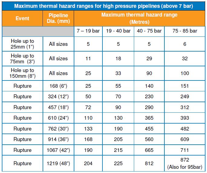

121 GD/PR/EM/ of 158

122 GD/PR/EM/ of 158 For determining safe distances for setting up control points it is recommended that the above distances are doubled. The above distances assume that individuals will be able to move away from the fire. They are not distances from any fire at which individuals would be able to safely stand for any significant length of time. For determining safe distances for setting up control points it is recommended that the above distances are doubled. Note: The apparent inconsistencies are due to the HP table being modelled on a crater with higher, narrower flames, and the Below 7bar Tables being modelled on a trench with lower wider flames Other gas escape locations Gas may be found to be escaping from: a) Third Party Gas Transporters pipelines b) Other pipelines, where Cadent are not the ESP. c) Mines, Sewer or Landfill sites. d) Other potentially Flammable / Explosive sites and vessels.
123 GD/PR/EM/ of 158 Smells emanating from other sources may also give low-level gas detection readings: a) Rotting vegetation or refuse; b) Newly creosoted woodwork; c) Fuel vapours, e.g. at bus stops or petrol stations; d) Sewer vent pipes; e) Non natural gas pipe work systems or bottled gas; f) Un-burnt gas present in the products of combustion from appliances. g) Insecticides or chemicals from crop spraying. Unless there are no Gas Network pipes in the surrounding area, never assume that piped natural gas is not the cause. Any gas readings obtained should be assumed to be from piped natural gas until proved otherwise. Where it is suspected that piped natural gas is not the source, a Hydrocarbon filter should be used to eliminate erroneous gas detector readings. Where a site survey confirms that gas is emanating from a mine, sewer or landfill site, and is not distributed natural gas, contact Dispatch who will pass the report details on to the responsible organisation. For example: a) Naturally occurring gas - Local Authority. b) Sewer gas - Local Water Company. c) Mine gas - (Contact the Coal Authority on to enquire if there a mine gas polygon in the general area). d) Landfill gas - Owners of landfill sites. e) Localised chemical or petrol spillage / leakage
124 GD/PR/EM/ of 158 Gas produced from a mature landfill site can be either heavier or lighter than air depending on its composition. About 65% of the gas produced is methane, the remainder being predominantly carbon dioxide. Natural gas detection equipment may not give an accurate reading of the gas level. Where landfill gas is suspected care shall be taken due to the potential hazards from its nonflammable characteristics, i.e. toxicity and / or asphyxiation Details should be passed to Dispatch who shall contact the responsible organisation / Emergency Service Provider, who should provide confirmation of acceptance. Operatives shall remain on site until released by Dispatch or the responsible ESP. If in any doubt about what action is required contact an Operational FLM Liquid Natural Gas (LNG) sites Special provision under the Control of Major Accident Hazards (COMAH) has been made to cover gas escapes at LNG sites and all remedial actions required are determined through emergency procedures maintained and implemented by the site occupiers. Any Operatives asked to attend an emergency situation at any of these sites shall contact their Operational FLM for further guidance Independent Gas Transporters (igt s) The company acts as an Emergency Service Provider (ESP) for IGT s which means that we will attend to all reported gas escapes in line with normal EM72 procedures and make a permanent repair where required. However, where the escape is on the external infrastructure (mains and services) belonging to the IGT s network and we are unable to affect the permanent repair due to engineering reasons such as non-standard pipe size, the IGT should arrange for an alternative provider to carry out the permanent repair. Note: The IGT cannot be requested to arrange a permanent repair on an escape until the gas leak location has been identified, the source(s) of the escape(s) have been secured by either temporary or interim techniques as per EM74, and the absence of gas has been proven where practicable.
125 GD/PR/EM/ of 158 The following details shall be passed to Dispatch; 1. The correct address of the property/properties affected. 2. Details of the reported emergency. 3. Details of work already carried out; i.e. temp wrapped main. 4. Details of company responsible for damage; if applicable. 5. Details of any properties with customers left off gas (existing requirement). Until a formal handover has been confirmed, continue to monitor the escape in line with normal OSGEM procedures. Where a PEMS contract is confirmed permanent replacement / repairs to leaking meters, meter governors, meter fittings can be completed.
126 GD/PR/EM/ of 158 All work carried out on an igt site is chargeable including both internal gas or fumes work and any external damages. If a consumer is left without gas alternative heating and cooking provision should be provided in line with current vulnerable customer procedures Liquid Petroleum Gas (LPG) sites Where it is clearly defined that a reported gas escape is emanating from an LPG supplied pipe, network or appliance then contact Dispatch to ensure that the details are passed to the relevant LPG supplier or their appointed ESP. LPG installations which may be encountered include: a) Bulk tank Feeding multiple properties via metered supplies. b) Bulk tank feeding a single property (no meter) c) Cylinder installations LPG emergencies are very similar to those encountered on natural gas networks but additional problems may occur due to the nature of the supply and properties of the gas. The four main potentially hazardous situations which may arise are: 1. Liquid leakage. 2. High pressure vapours escape. 3. Low pressure vapours escape. 4. BLEVE (Boiling Liquid Expanding Vapour Explosion) When dealing with an LPG emergency follow the same priority actions to safeguard life and property and take the following additional actions: Damage and fire Any LPG plant or vessels that have been exposed to fire, or subject to severe mechanical impact; e.g. hit by a vehicle, or dropped, should be checked for damage. Even though leaks may not be immediately present, they can subsequently occur, including potentially catastrophic failure and BLEVE. It is therefore, important that until an assessment can be carried out, restrict access to the area and contact the Fire Service.
127 GD/PR/EM/ of 158 Any vessel involved in a fire may suddenly rupture. Change in the size of the fire, or noise from the Pressure Reduction Valve may be an indication, but there may be no warning. If in doubt do not approach the vessel. A BLEVE is an explosion of a gas cylinder that happens when the cylinder wall has failed and the liquid gas explodes, causing a fireball with a size and duration depending on the amount and type of gas released. This is not a manageable emergency other than quick evacuation out of an exclusion zone that takes into account that propane gas cylinders can be thrown 50 meters away in any direction, the minimum safe distance from a potential BLEVE involving propane cylinders of 19 kg and above is 100 meters. There is normally no warning when a vessel might fail, though if the PRV is operating, failure may well be imminent, especially if flames are impinging on the vessel. An increase in the pitch (frequency) of the PRV discharge is also an indication that vessel failure is about to occur. If there is the possibility of a BLEVE occurring evacuate the area, including yourself, and contact the Fire Service Bulk tank installations In all cases where leakage from the high pressure side of a bulk tank occurs and it cannot be controlled by turning off the isolation valve, prevent ignition, evacuate the area, inform Dispatch and call the Fire Service. In cases where the leak is from the low pressure side this can normally be controlled by turning off the outlet valve or ECV. Provide ventilation but remember that LPG is heavier than air so prevent ingress into drains etc Cylinders If a high pressure escape is encountered then if possible shut off the cylinder valve. If the valve cannot be closed and the cylinder is not in the open air then, providing it is safe to do so, remove the cylinder to open space. Keep the cylinder away from ignition sources and drains etc. If the escape persists and it is not possible to remove the cylinder, evacuate the area, prevent ignition, evacuate the area, inform Dispatch and call the Fire Service. Escapes on the low pressure side can normally be controlled by turning off the cylinder valve.
128 GD/PR/EM/ of LPG characteristics Leaks are normally identified by smell, noise or refrigeration (hoarfrost). LPG is heavier than air and will sink to the lowest levels. Particular caution shall be exercised when checking confined spaces such as cellars and voids. It can displace air increasing the potential for suffocation. Vapour can be ignited at a distance from the source of the escape. If LPG is encountered whilst using a machine calibrated for Natural Gas, the measured readings should be doubled i.e. a reading of 10% LEL becomes 20% LEL. Isolation of electrical switches should only be made if an LPG readings above and below does not exceed 35% LEL. Ventilation of a property can be achieved by opening doors and windows, but caution shall be exercised as the LPG can migrate to a lower level. Avoid coming into contact with the LPG, it can cause severe cold burns and saturate clothing which may subsequently be ignited. Suggested exclusion zones for LPG escapes Type of escape Distance (metres) Small vapour leak characterised by a smell of gas 30 Large vapour leak characterised by a loud hissing of gas 100 Liquid leak characterised by a roar of gas Theft of gas Theft of gas is the term used where there is evidence of tampering with either the meter installation or the service pipe and will usually involve un-metered gas being used. These situations should be handled carefully until all of the facts and information can be obtained and assessed. Examples of tampering / theft include; Meter connections reversed; Meter tilted; Inlet / outlet; unions worn or scored; Meter or Index tampered with; Meter by-passed (downstream of the ECV); Direct connection to ECV; Illegal gas service to property; Tee in service upstream of the ECV; Stolen meter; Different meter to that on records. Check the property for gas escapes including a tightness test on the downstream installation, where appropriate (where there is no access carry out letterbox checks ).
129 GD/PR/EM/ of 158 Where an escape or other safety hazard (e.g. unregulated supply) is discovered carry out appropriate actions to make safe. If any adversarial situations (threats/verbal abuse or violence etc.) are encountered, make a request to dispatch to consider circulating a 118 text to warn other staff. The following additional actions should also be carried out, where it is safe to do so; 1. Record details of evidence found (including photographs if possible) and any actions taken. 2. Record meter details and status of supply. 3. If meter is reversed / tilted etc. do not re-fit meter back into the correct position. If a tee has been fitted in the service pipe, upstream of the ECV, contact an Operational FLM in order to decide the next course of action which should include; a) Removal of the tee to prevent further theft of gas. b) Leaving the service live to the property, cap at the ECV or where there is no access wind down the HET. Where required this may involve relaying the service. c) Record all work carried out in order for costs to be calculated. Where possible recording the quantity and type of appliances and the size / type of property (this is required in order to estimate the amount of gas stolen). Raise a Tog form; report all details, including where there is no evidence of theft and leave the appropriate customer advice card. The Theft of Gas team will arrange follow up action including recovery of costs etc. where appropriate. Where a gas supply has been isolated because there is a serious safety concern, we have a duty of care towards vulnerable individuals (e.g. fan heater). A person is vulnerable if they are unable to safeguard their personal welfare or the personal welfare of other members of the household due to age, health, disability or severe financial insecurity. When required to assist a Shipper in the removal of a Supply Meter and other gas fittings record the name, job title & company name of the Shipper Representative. The meter should not be exchanged unless pre-booked under the TSE Hire Arrangements. The existing meter can be removed and retained by the representative if so requested. If you are unsure about the actions you should take on site contact an Operational FLM.

130 GD/PR/EM/ of Piggy backing of ECV s Piggybacking is the installation a new ECV directly after an existing ECV which is classified as a permanent repair technique This procedure can be used where the existing ECV is pressure tight but fails a let-by test and it is not possible to exchange the ECV. This procedure is suitable for low-pressure ¾ or 1 diameter ECV with BS 746 parallel male outlet thread and BS 21 (BSP) outlet thread up to and including Installation method: 1) Carry out a site-specific assessment to include the following: Check exposed metalwork with a Voltstick Check the condition of the service pipe looking for signs of corrosion especially at floor / wall entry points. If significant corrosion is observed arrange for the service pipe to be replaced; Ensure there is sufficient working room to allow the second ECV to be fitted and ensure future access by the consumer is not impeded. 2) Mark the position of the standpipe relevant to its entry position to enable checks to be made for movement of the standpipe during installation of the ECV. If the service pipe is disturbed during installation of ECV, immediately check the whole service pipe inside and outside the property for leakage and arrange for the service to be cut off immediately as a safety precaution. 3) Turn off the existing ECV and disconnect the downstream pipe / fitting.
131 GD/PR/EM/ of 158 For BS746 threaded ECV s continue by using components: Copper washer (SAP 4753); Union (SAP 1568); ECV; 3M Shrink sleeve. 4) Assemble the new ECV and Meter Union Liner (use approved gas thread sealant on the threaded joint prior to tightening) and fit a cap on the outlet. 5) Insert a copper washer into inlet seating of the Meter Union nut (apply a film of jointing paste to the copper washer). 6) Connect inlet of new ECV to outlet of existing ECV and tighten until finger tight, make a reference mark on one edge of the meter union nut and body of the existing ECV 7) Using the reference marks, tighten the nut by at least two flats. 8) Open the new and existing ECV s apply approved leak detection fluid to all exposed joints to confirm tightness. If it fails, tighten the nut up to 2.5 flats and re-test. (If the connection continues to leak, replace the copper washer with a new one and repeat steps above). 9) For BS21 (BSP) threaded ECV s continue by using components: Equal socket, barrel nipple, ECV, 3 M shrink sleeve. 10) Assemble the new components and seal all new threaded joints up to the ECV with jointing paste. 11) Test for leakage and service pipe movement, close the valve then remove the gland body and adapter. 12) Undertake a full gas detection survey of the entire length of the service pipe to ensure no leakage is present and for high rise installations check along lateral and connections to riser. 13) Secure the existing ECV in the open position using the locking screw, remove the handle and apply a 3M EL15 shrink sleeve to encapsulate the existing ECV. 14) Re-connect downstream pipe / fitting and label the service appropriately.
132 GD/PR/EM/ of Exchanging an ECV using a Synthotec stopper Exchange Meter Control Valves Checklist 1. Could the exchange be carried out by isolating the Supply? 2. Determine condition of the Service Pipe 3. Is there adequate space and ventilation to carry out the exchange? 4. Gas detection equipment safety check 5. Turn off and test the installation for Tightness 6. Isolate adjacent Electrical Appliances 7. Chalk or mark Service Pipe to check for movement 8. Fit Temporary Continuity Bonds / Remove and cap the Gas Meter 9. Make sure that there is a fire extinguisher available 10. Inform customer of intending actions 11. Be aware you may be working in a confined space Using the kit. 1. Inspect the equipment for damage and select the correct sized stopper and introduction adapter. 2. Confirm that the replacement ECV is the correct size. 3. Push the rod through the gland body and attach the stopper, apply silicone grease to the stopper and seals (Fig l). 4. Screw the adapter and the gland body onto the existing ECV. 5. Open the ECV and introduce the stopper into the Service Pipe, pull back a couple of millimetres to reverse cones on the stopper (Fig 2). 6. Attach U-gauge tube to the nipple on the gland body to ensure an effective seal has been achieved (zero pressure).
133 GD/PR/EM/ of Remove the gland body and the adapter from the ECV; carefully remove the existing ECV from the Service Pipe (Fig 3). 8. Clean the threads on the Service Pipe and apply jointing paste. 9. Ensuring the replacement ECV is in the open position, screw onto the Service Pipe and carefully tighten. 10. Attach the adapter and the gland body to the replacement ECV, withdraw the stopper into the gland body. 11. Test for leakage and pipe movement, close the valve then remove the gland body and adapter. 12. Reconnect the Gas Meter, test for tightness and purge the supplies.
134 GD/PR/EM/ of Testing / Re-commissioning of House Entry Tees 1) Check the ECV is in the closed position, remove the ECV cap and fit pressure test point and gauge. 2) Open the ECV and monitor for let by across the closed house entry tee. There should be no pressure increase on the gauge. (If there is a pressure increase the house entry tee cap should be removed and the shut off device checked to ensure that it is fully closed) 3) Remove house entry tee top cap or plug to gain access to the house entry tee s shut off device. 4) Lift the house entry tee s shut off device up to the fully open position. 5) Replace the house entry tee cap/plug and test cap using approved leak detection fluid 6) Use approved leak detection fluid to test all joints and check the ECV for external leakage. 7) Conduct a let by test on the ECV by closing the ECV and disconnecting the pressure gauge to reduce the pressure to zero. Reattach to monitor for let by across the closed ECV for 1 minute. There should be no pressure increase. If there is pressure increase the ECV should be replaced and service test repeated. 8) Use an approved gas detector to test the entry and exit points of the house entry tee through the wall. There should be no visible signs of leakage and a reading of 0% LEL shall be obtained from all joints for the test to be acceptable. 9) If leakage is noted, the service shall be re-laid. 10) Replace the cap on the ECV or re-connect the meter inlet.
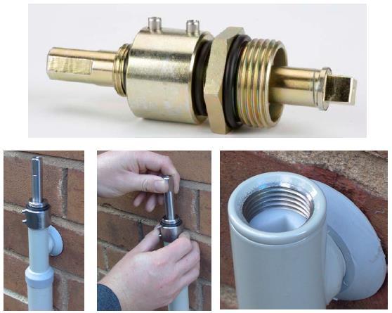
135 GD/PR/EM/ of 158
136 GD/PR/EM/ of Sulfidation of natural gas installations Sulfidation is a phenomenon caused by hydrogen sulphide (H 2 S), which is a naturally occurring constituent of many natural gas reserves/gas fields and concentrations in the Network are limited to 5mg/m 3 under GS(M)R. The gas in our Network is monitored to ensure compliance with the regulations. H 2 S can, under certain circumstances, react with the copper gas pipework in consumer s premises to form a film of copper sulphide (Cu 2 S) on the internal surfaces of the pipework. Where this copper sulphide flakes off, it has the appearance of small graphite flakes and is often referred to as Black Dust. This dust can be carried by the gas flow into appliances, where it can accumulate and in some cases block gas valves, filters, injectors and pilot lights, etc. What advice should be given to the gas user? The gas user should be advised that the problem has been caused by the copper pipe in their property reacting with the gas (some copper appears to be more susceptible to this). They should contact a Gas Safe Registered engineer to determine whether replacing the copper pipe, fitting filters to affected appliances or blowing through the pipework to remove deposits would help alleviate the problem. Further information and guidance can be obtained via the HSE and Gas Safe Register.
137 GD/PR/EM/ of 158 Appendix A Flowchart Initial actions
138 GD/PR/EM/ of 158 Appendix B Downstream escape

139 GD/PR/EM/ of 158 Appendix C Upstream escape
140 GD/PR/EM/ of 158 Appendix D CO alarm
141 GD/PR/EM/ of 158 Appendix E CO checking other properties
142 GD/PR/EM/ of 158 Appendix F No access
143 GD/PR/EM/ of 158 Appendix G No trace outside escape
144 GD/PR/EM/ of 158 Appendix H Poor pressure
145 GD/PR/EM/ of 158 Appendix I No gas
146 GD/PR/EM/ of 158 Appendix J Evacuation

147 GD/PR/EM/ of 158 Appendix K OSGEM Risk Score
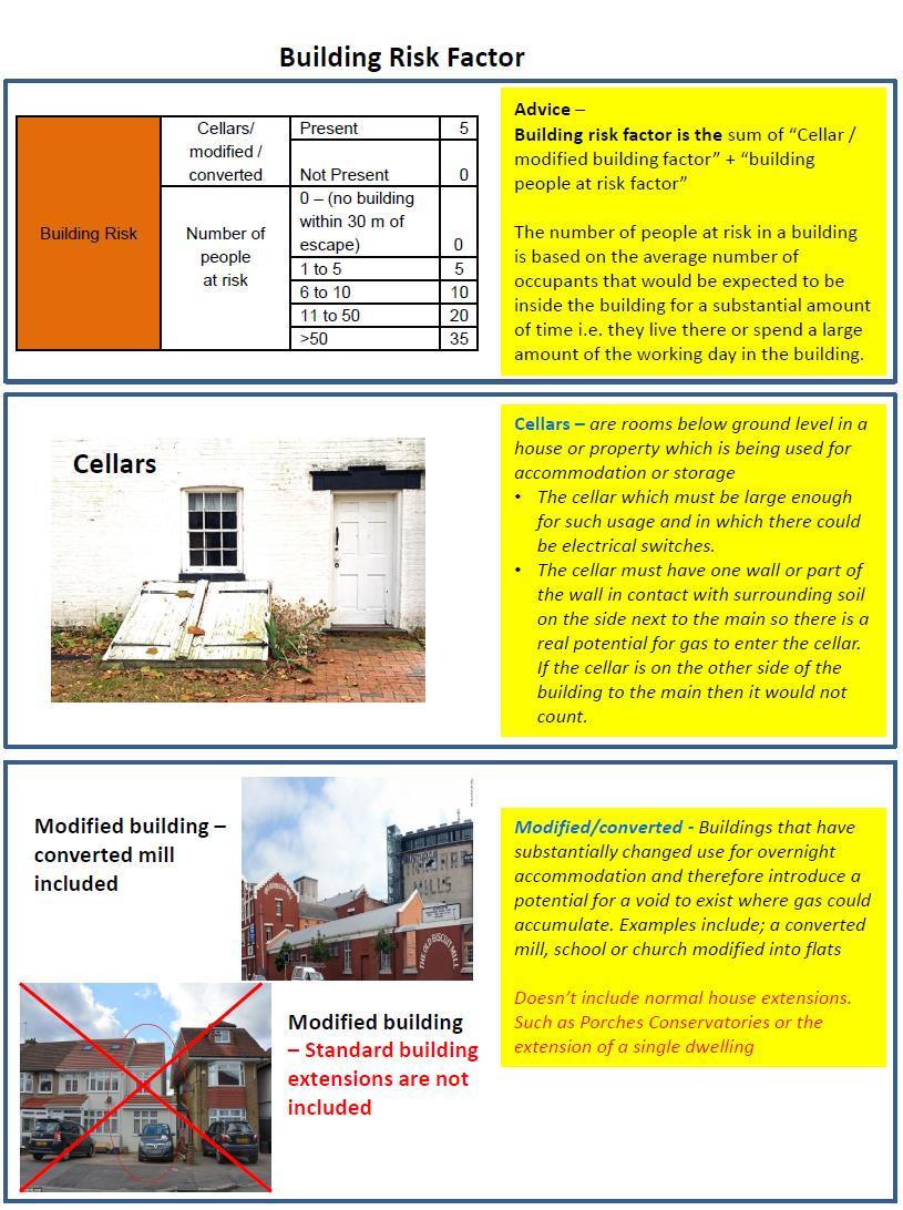
148 GD/PR/EM/ of 158
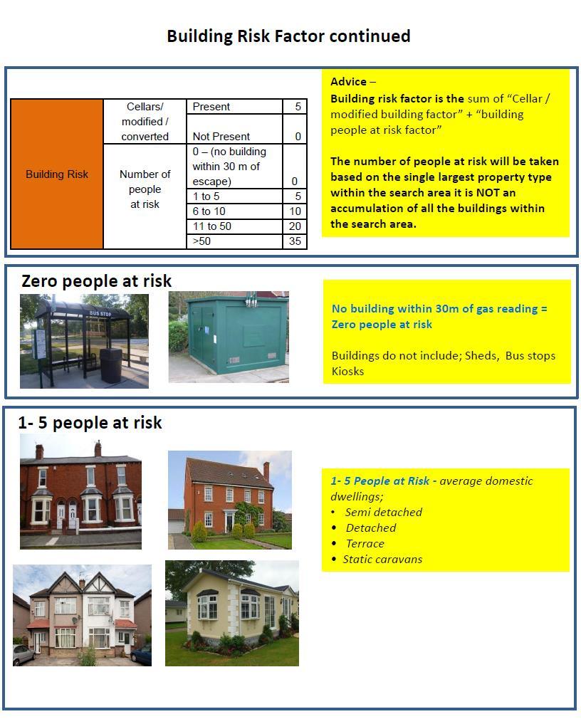
149 GD/PR/EM/ of 158

150 GD/PR/EM/ of 158

151 GD/PR/EM/ of 158
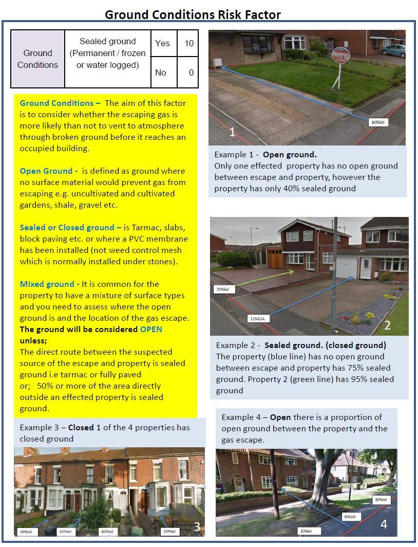
152 GD/PR/EM/ of 158
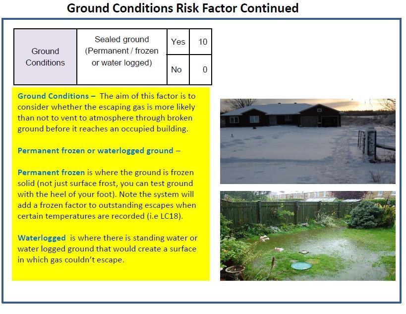
153 GD/PR/EM/ of 158
154 GD/PR/EM/ of 158 Appendix L Those requested to review document Name Position Date Mark Woolham Martin Neat Darren Miller Andrew Huckerby Nicola Wilkinson Graham Davies Michael Murray Craig Hansbury Matthew Kitchin Jason Mrksic Ricky Teagle Craig Gibson Amber Fletcher Ian Fitt James Fisk Richie Watterson Ian Donohue Robert Gray Stephen Hughes Steve Cosway Andy Turner Joanne Berry Dave Clarke John Greensmith Robert Mann Earl Richards Reece Sargent Shaun Soloman Andrew Moore Bryn Wheatley Jonathan Oliver Christopher Clarke Network Manger NW Emergency Network Manager - West Mids Emergency East Anglia ERR Network Manager Network Manager - East Midlands Emergency London Emergency Network Manager Network Supervisor Network Supervisor Network Engineer Industrial and Commercial Network Supervisor Network Engineer Network Supervisor Technical Engineer East of England Customer Specialist Policy Engineer Compliance Officer NL ESE-Assessor-Internal Verifier Skills & Competence Assessor Network Supervisor Assessor-Internal Verifier Compliance Assurance Specialist Policy Engineer Technical Specialist (ER & R West) Performance & Assurance Team Network Engineer Shift Controller Skills & Competence Assessor Project Officer Lead Engineer Network Engineer Network Engineer Skills and Competency Assessor West Midlands SHE Advisor GMB Senior TU Rep-West Midlands
155 GD/PR/EM/ of 158 Mark Edwards John Capper Mark Arthur Alun Stevens Chris Rison John Duckworth James Harrison Hilary Buxton Dave Garner Alison Regan Simon Eves Ian Aldridge Network Manager Repair Network Engineer WM Business Change Delivery Manager Change Planning Manager Head of Operations, ER&R East Head of Operations - ER&R West Head of Operations, London ERR Head of Engineering ER&R Performance Manager Skills & Competence Manager Scheduling & Dispatch Manager Head of SHES
156 GD/PR/EM/ of 158 Appendix M - Document Summary Purpose This work procedure was approved by the Head of Engineering, in for use throughout the company. Users should ensure that they are in possession of the latest edition and related bulletins by referring to the document library of Safety and Engineering documents available on the company Infonet. Compliance with this safety and engineering document does not confer immunity from prosecution for breach of statutory or other legal obligations. Responsibilities This document applies to all those working directly for Gas Distribution e.g. employees, or under the direction of Gas Distribution, e.g. contractor mate working in a direct labour team. Background This document has been developed for Operatives who are directly responsible for attendance, investigation and site actions at upstream and downstream gas escapes and other emergencies. It has been developed to provide comprehensive and concise guidance to ensure consistency of application throughout the company and defines those activities to be undertaken by Operatives. Failure to comply with the requirements of this document could result in the company and/or individual employees facing criminal charges. Failure to comply with the requirements of this document could also result in individual disciplinary action. Gas emergency work takes priority over any other Network activity Copyright 2017 Cadent Gas Distribution - All Rights Reserved
157 GD/PR/EM/ of 158 Appendix N - Changes from previous version Description Date Author All HS&E subjects have been moved to the front end of the document. Guidance provided for use of mobile devices Initial actions, including evacuation and reoccupation in one section. Guidance provided for electric cross bonding issues Priority actions, Evacuation and re-occupation criteria clarified. No access and Rights of Entry clarified. Clarification of site handover and leaving site. Dealing with internal gas escapes clarification on the actions required at domestic and I&C premises. Domestic tightness testing requirements clarified CO section has been updated to bring together all the information published since the last version of EM72 and additional guidance provided for dealing with adjoining properties use of gas detection equipment. Unsafe situations updated to reflect v7 of GIUSP and how to ensure the customer fully understands the safety issues found. RIDDOR section simplified in line with HSE guidelines. Repair section reviewed to ensure consistency with EM74. OSGEM sweep search clarified. OSGEM Building checks clarified - Check for gas in or under all adjacent properties within 15m either side of the report and all of those opposite within 30m. (This is in accordance with guidance originally issued as SEI 190). OSGEM programming escapes scores updated. OSGEM returning to a programmed escape actions clarified OSGEM sweep and bar hole requirements clarified. OSGEM consistency guide added as an appendix Engineering Bulletins 112, 175, 414, 431, 475, 482, 518 & 520 have been incorporated. Pressure problems Procedure updated but still to be confirmed pending industry agreements Flow charts added to aid understanding of processes 13/06/2017 Dave Thorley
158 GD/PR/EM/ of 158 Cadent Ashbrook Court Prologis Park Central Boulevard Coventry CV7 8PE Copyright Cadent Gas Distribution plc. 2017, all rights reserved. No part of this publication may be reproduced in any material form (including photocopying and restoring in any medium or electronic means and whether or not transiently or incidentally) without the written permission of Cadent Gas Distribution plc. except in accordance with the provisions of the Copyright, Designs and Patents Act 1988.
Safe Work in Confined Spaces
 Safe Work in Confined Spaces This publication is prepared by the Occupational Safety and Health Branch Labour Department Edition November 2010 This publication is issued free of charge and can be obtained
SAFETY AND HEALTH PROGRAM
 PROGRAM NUMBER NO. PAGES 05-005 10 REVISION ISSUE DATE Revision 2 11/1/2005 SAFETY AND HEALTH PROGRAM Confined Space Entry 1.0 INTRODUCTION Confined Space Entry is a serious workplace hazard, capable of
How To Safely Dig For Natural Gas
 PNG DIAL B4-U-DIG book_final_nu 5/1/05 3:24 PM Page 2 Phoenix Natural Gas,197 Airport Road West, Belfast BT3 9ED. Tel. 08454 55 55 55. www.phoenix-natural-gas.com PNG DIAL B4-U-DIG book_final_nu 5/1/05
BUILDING A WORLD OF DIFFERENCE. Safe work in confined spaces
 Health & Safety Training Safe work in confined spaces Agenda Introduction What is a confined space? What are the hazards? Safe system of work Emergency arrangements Summary of pre-entry checks Questions
FLAMMABLE LIQUIDS COMPLIANCE NOTE
 Issued by: Heather Rice Page: 1 of 7 COMPLIANCE NOTE INTRODUCTION This document provides additional guidance to support the Arrangement on Flammable Liquids (Ref No. CYC/HS/A27) CONTENTS Section Topic
Natural Gas Emergencies
 Natural Gas Emergencies Purpose To protect the personnel within the department, and citizens from the hazards involved in a natural gas emergency. The Incident Commander is to use his/her best judgment
Carbon monoxide. General information
 Carbon monoxide General information Key Points Fire Flammable gas May react violently with other substances Use fine water spray with normal fire-fighting clothing and breathing apparatus Health Toxic
WORKING IN CONFINED SPACES GUIDELINES
 WORKING IN CONFINED SPACES GUIDELINES Contents 1 Introduction... 2 2 Scope... 2 3 Definitions... 2 4 Responsibilities... 3 4.1 Permit Authoriser... 3 4.2 Permit Receiver... 3 4.3 Responsible UOW Officer...
PROCEDURES PREVENTION OF ACCIDENTAL IGNITION
 Page No: 1 of 7 6.0 PURPOSE (192.751) All possible precautions shall be exercised to prevent the accidental escape and ignition of gas. Whenever possible, potential sources of ignition should be eliminated
Ontario Fire Code SECTION 5.13 DIP TANKS. Illustrated Commentary. Office of the Ontario Fire Marshal
 Ontario Fire Code SECTION 5.13 DIP TANKS Illustrated Commentary Office of the Ontario Fire Marshal Dip Tanks Illustrated Commentary 1 5.13.1. Location 5.13.1.1. Dip tank operations involving flammable
Natural Gas Safety. What You Need to Know
 Natural Gas Safety What You Need to Know Knowledge is Safety Approximately 52% of all U.S. households use natural gas for Home heating Cooking Water heaters Gas logs Outdoor gas grills Our Local History
Having a gas appliance installed or serviced? Doing home improvements?
 Keeping you safe Having a gas appliance installed or serviced? Think Safety. Think RGI. In your home, safety comes first. If you are having a gas appliance installed, serviced or repaired, always use a
SITE CONTRACTOR PROCEDURES
 SITE CONTRACTOR PROCEDURES Asset Collection Type B Assets are considered High risk ; the site activities must be in accordance with Graysonline contractor procedures and are to be collected by appointment
Installation Instructions for Alarm Module Kit A043F059
 Instruction Sheet 07-2013 Installation Instructions for Alarm Module Kit A043F059 1 Introduction The information contained within is based on information available at the time of going to print. In line
WORK IN CONFINED SPACES
 WORK IN CONFINED SPACES STFC Safety Code No 11 Rev. 1.4, Issued April, 2015 Note - This document may have been superseded by a more recent version. Revisions 1 Initial Launch November 2007 1.1 Minor changes
READ FIRST. Confined Space Entry Procedure. San José State University Environmental Health and Safety. Confined Space Entry Procedure
 READ FIRST 1. The purpose of a is to save lives by controlling the inherent hazards of a confined space prior to entry. a. If possible, avoid entering a confined space. Every consideration should be given
Confined spaces can be deadly. What is a confined space?
 Confined spaces A brief guide to working safely This leaflet explains what you, as an employer, may need to do to protect your employees when working in confined spaces. It will also be useful to the self-employed
SL280UHV SERIES GAS FURNACE WARNING
 2010 Lennox Industries Inc. Dallas, Texas, USA 506677 01 11/2010 Supersedes 506409 01 SL280UHV SERIES GAS FURNACE Litho U.S.A. FIRE OR EXPLOSION HAZARD. Failure to follow safety warnings exactly could
Fuels Safety Program FS- 072-06 7 DIRECTOR S PUBLIC SAFETY ORDER
 Ref. No.: Rev. No.: Fuels Safety Program FS- 072-06 7 DIRECTOR S PUBLIC SAFETY ORDER Date: January 13, 2006 IN THE MATTER OF: THE TECHNICAL STANDARDS AND SAFETY ACT, 2000, S.O. 2000, c. 16 - and - ONTARIO
ALVERNIA UNIVERSITY OSHA REGULATION: 29 CFR 1910.252 WELDING, CUTTING, AND BRAZING ( HOT WORK ) SECTION: 3600
 SECTION: 3600") OSHA REGULATION: 9 CFR 90.5 WELDING, CUTTING, AND BRAZING ( HOT WORK ) A. POLICY. This procedure follows requirements set forth in 9 CFR 90.5.. This policy applies to all Hot Work operations being done
OSHA REGULATION: 9 CFR 90.5 WELDING, CUTTING, AND BRAZING ( HOT WORK ) A. POLICY. This procedure follows requirements set forth in 9 CFR 90.5.. This policy applies to all Hot Work operations being done
Notes. Material 1. Personal Protective Equipment 2.
 29CFR 1926.20(b)-Accident Reduction, 29CFR 1926.21- Safety Training & Education 29CFR 1926.20(a)-Unsafe Working Conditions 29 CFR 1910.132-138, the "Personal Protection Equipment" standard. & 20 CFR 1910.134
TIG INVERTER INSTRUCTION MANUAL
 TIG INVERTER INSTRUCTION MANUAL Contents Warning General Description Block Diagram Main Parameters Circuit Diagram Installation and Operation Caution Maintenance Spare Parts List Troubleshooting 3 4 4
Operating instructions
 6302 6959 02/2006 GB For the user Operating instructions Logano G215 WS Oil and gas-fired boilers Please read thoroughly before use. Overview Regulations and directives Installation: 90/396/EEC gas appliance
Controlling fire and explosion risks in the workplace
 Controlling fire and explosion risks in the workplace A brief guide to the Dangerous Substances and Explosive Atmospheres Regulations Introduction to DSEAR This leaflet provides a brief introduction to
Confined Spaces Safe Working Practices
 Confined Spaces Safe Working Practices INTRODUCTION Any person planning, authorising, directing or supervising work in CONFINED SPACES must comply with the Confined Spaces Regulations 1997. These notes
Upstate NY Recovery assistance information
 Upstate NY Recovery assistance information www.nationalgrid.com Emergency contact information National Grid Customer Service 1-800-642-4272 National Grid Gas Emergency: 1-800-892-2345 Federal Emergency
Certain specific properties of compressed gases make them highly useful in various research activities.
 GAS CYLINDER SAFETY Introduction Certain specific properties of compressed gases make them highly useful in various research activities. These gases, however, can be dangerous if not handled in an appropriate
Metal welding safety. Guidance Note. Practical advice for employers on controlling hazards when welding. June 2011. Background. How to use the table
 Guidance Note Metal welding safety Practical advice for employers on controlling hazards when welding. June 2011 Background Metal welding involves the application of heat to join two metals together. The
CONFINED SPACE PROCEDURE
 Document uncontrolled when printed Procedure ID no 0460/05 CONFINED SPACE PROCEDURE This procedure is applicable to: All Department of Education and Children's Services employees. DOCUMENT CONTROL Managed
Material Safety Data Sheet
 1 IDENTIFICATION OF THE SUBSTANCE AND COMPANY a) SUBSTANCE: Natural Gas b) COMPANY: Bord Gáis Éireann PO Box 51 Gasworks Road Cork Telephone: (021) 453 4000 Emergency Telephone: 1850 20 50 50 2 COMPOSITION/INFORMATION
STORE HAZARDOUS SUBSTANCES SAFELY. incompatibles gas cylinders
 STORE HAZARDOUS SUBSTANCES SAFELY Suitable containers incompatibles gas cylinders Oxy-Acetylene welding flammable substances 35 36 STORE HAZARDOUS SUBSTANCES SAFELY STORE HAZARDOUS SUBSTANCES SAFELY Storing
Dealing with. www.stroud.gov.uk. Dealing with Asbestos STROUD DISTRICT COUNCIL WARNING CONTAINS ASBESTOS
 www.stroud.gov.uk Dealing with Management of Asbestos containing materials Many building materials may contain asbestos fibres, often this does not mean that they pose any danger if they are not disturbed.
Heading FACT SHEET. Overview. www.safeworkaustralia.gov.au
 ELECTRICAL RISKS AT THE WORKPLACE Heading FACT SHEET Overview This fact sheet provides general guidance for persons conducting a business or undertaking (PCBUs) and workers on managing electrical risks
Confined Space Procedures
 Confined Space Procedures Table of Contents Purpose... 2 Primary Objectives... 2 Operational Objectives... 2 Legislation... 2 Definitions... 2 Responsibilities... 4 1. Vice-President (Administration) 2.
RESTRICTED ACCESS AND CONFINED SPACES
 Health & Safety Services Unit name goes here Safety Code of Practice 39 1 st Edition, July 2011 RESTRICTED ACCESS AND CONFINED SPACES University of Reading 2015 Page 1 Contents 1 Summary... 3 2 Introduction...
IN CASE OF EMERGENCY. Emergency Telephone Number 112
 IN CASE OF EMERGENCY Emergency Telephone Number 112 Police, Fire, Ambulance Dial 112 in case of fire, medical emergency, serious or life threatening traffic or other accident. Tell the operator: What has
A guide to landlords duties: Gas Safety (Installation and Use) Regulations 1998. What type of property is covered?
 Regulations 1998. What type of property is covered?") Landlords A guide to landlords duties: Gas Safety (Installation and Use) Regulations 1998 This leaflet is aimed at landlords and explains some of the main requirements of the Gas Safety (Installation and
Landlords A guide to landlords duties: Gas Safety (Installation and Use) Regulations 1998 This leaflet is aimed at landlords and explains some of the main requirements of the Gas Safety (Installation and
THE NEWCASTLE UPON TYNE HOSPITALS NHS FOUNDATION TRUST SAFE USE AND STORAGE OF LIQUID NITROGEN AND SOLID CARBON DIOXIDE (DRY ICE)
") THE NEWCASTLE UPON TYNE HOSPITALS NHS FOUNDATION TRUST SAFE USE AND STORAGE OF LIQUID NITROGEN AND SOLID CARBON DIOXIDE (DRY ICE) GUIDANCE AND INFORMATION Effective: February 2007 Review February 2010
THE NEWCASTLE UPON TYNE HOSPITALS NHS FOUNDATION TRUST SAFE USE AND STORAGE OF LIQUID NITROGEN AND SOLID CARBON DIOXIDE (DRY ICE) GUIDANCE AND INFORMATION Effective: February 2007 Review February 2010
Policy for the Management of Asbestos in the Workplace
 Southwark Council Management of Asbestos in the Workplace November 2011 Page 1 of 15 CONTENTS 1. INTRODUCTION... 3 2. POLICY STATEMENT... 3 3. ASBESTOS RISK CLASSIFICATION SCHEME... 5 4. SAMPLING OF ASBESTOS
Take care with oxygen Fire and explosion hazards in the use of oxygen
 Fire and explosion hazards in the use of oxygen This leaflet provides information on the fire and explosion hazards in the use of oxygen. It is for anyone who uses oxygen gas in cylinders. Hazards from
Pressure Vessels (Air Compressors) and LPG Tanks
 and LPG Tanks") Pressure Vessels (Air Compressors) and LPG Tanks 1. Identification of Workplace Hazard Any container, tank or vessel that contains pressurized material is a potential hazard to employees due to the force
Pressure Vessels (Air Compressors) and LPG Tanks 1. Identification of Workplace Hazard Any container, tank or vessel that contains pressurized material is a potential hazard to employees due to the force
Underground Storage Tanks
 Underground Storage Tanks An Informational and Guidance Document for the University Community. Please contact Yale Environmental Health and Safety for latest Regulatory Requirements. A typical UST installation
The terms hazard and risk are often used, which we define as the following:
 Fire Safety Last updated in October 2010 This information sheet aims to give safety reps a basic understanding of fire safety and fire risk assessments under the current law. More detailed information
Confined Space Entry Procedure Worksheet
 1. Location Exact name and location of space to be entered. Confined Space Entry Procedure Worksheet 2. Hazard Identification & Determination - (circle all that apply) a. Tasks to be performed. Welding/Cutting
Emergency Response Guide
 Emergency Response Guide Honda Fuel Cell Vehicle Prepared for Fire Service, Law Enforcement, Emergency Medical, and Professional Towing Personnel by American Honda Motor Co., Inc. Contents Key Components...2
General Confined Space Awareness
 Confined Spaces General Confined Space Awareness Confined spaces can be found in many industrial settings, from steel mills to paper mills, from shipyards to farms, and from public utilities to the construction
Gas appliances. Get them checked Keep them safe. The problem
 Gas appliances Get them checked Keep them safe The problem Every year about 14 people die from carbon monoxide poisoning caused by gas appliances and flues which have not been properly installed or maintained.
Fire Risk Assessment Safety Checklist
 Fire Risk Assessment Safety Checklist This checklist has been prepared to help you comply with The Regulatory Reform Fire Safety Order 2005 What is the Regulatory Reform (Fire Safety) Order 2005? The Regulatory
Work Permits. A Health and Safety Guideline for Your Workplace. When is a Work Permit Needed? What is a Work Permit? Why use a Work Permit?
 A Health and Safety Guideline for Your Workplace What is a Work Permit? A work permit is a written form used to authorize jobs that expose workers to serious hazards. It identifies the work to be done,
Electrical Practices for Construction Work
 1. Purpose Electrical Practices for Construction Work The purpose of this Code is to provide practical guidance and set minimum safety requirements for electrical practices on all construction sites in
SAFETY SIGNAGE PROCEDURE
 Page 1 of 10 SAFETY SIGNAGE PROCEDURE 1.0 PURPOSE 1.1 To enable a reference to signage to meet legislative requirements and ensure in cases of emergency appropriate signage is visible. 2.0 SCOPE 2.1 This
Fire Safety Risk Assessment Checklist for Residential Care Premises
 Checklist for Residential Care Premises Name of Premises: Address of Premises: Name of Responsible Person: What area / location does the assessment cover? Does the assessment cover the whole site YES or
Fire safety advice for landlords
 YOU CAN PREVENT IT Fire safety advice for landlords Introduction Each year there are over 50,000 fires in dwellings in the UK. These result in around 300 hundred fatalities and several thousand serious
ecomax Instructions for use Wall hung room sealed fan assisted condensing boilers For the user
 For the user Instructions for use ecomax Wall hung room sealed fan assisted condensing boilers ecomax 63/ E ecomax 68/ E ecomax 6/ E ecomax 635 E ecomax 84/ E ecomax 88/ E ecomax 835 E GB Table of contents
This leaflet provides information on
 This leaflet provides information on the fire and explosion hazards in the use of oxygen. It is for anyone who uses oxygen gas in cylinders. HSE8(rev2) Hazards from oxygen Oxygen gas in cylinders is used
COMPRESSED GASES. 1.2 The contents of each cylinder and container must be clearly identified (by tag or stamp) on the cylinder.
 on the cylinder.") Page 1 of 5 COMPRESSED GASES A compressed gas is defined as any mixture of gases in a container with a pressure exceeding 40 psi. at 70 o F, or 104 psi. at 130 o F; or any flammable liquid with an absolute
Page 1 of 5 COMPRESSED GASES A compressed gas is defined as any mixture of gases in a container with a pressure exceeding 40 psi. at 70 o F, or 104 psi. at 130 o F; or any flammable liquid with an absolute
natural gas Control control of of Natural Gas in Emergency Situations
 control of Control of Natural Gas natural gas in Emergency Situations 800 North Third Street Suite 301 Harrisburg, PA 17102 717.901.0600 www.energypa.org G as company representatives are available around
Millersville University - Office Of Environmental Health & Safety Scope & Application
 Confined Space Entry Millersville University - Office Of Environmental Health & Safety Scope & Application The Confined Space Entry (CSE) program applies to the safe working practices for entering and
Compressed Gas Cylinder Program
 Department of Environmental Health & Safety Procedures Compressed Gas Cylinder Program March 2010 Compressed Gas Cylinder Program Page 1 of 8 Table of Contents I. Introduction II. III. IV. Policy Scope
CATERING CONTRACTORS General Code of Safety Practice
 Residential & Business Services Director s Office CATERING CONTRACTORS General Code of Safety Practice CONTENTS 1 Introduction 2 2 Commencement of Work 3 3 Vehicles 3 4 Temperature control 3 5 Food hygiene
Excavation & Trenching Procedure
 Excavation & Trenching 1. Overview The will ensure, as far as is reasonably practicable, that the conduct of work relating to excavation and trenching will not be harmful to the health and safety of employees
IGEM/UP/16 Communication 1756
 Communication 1756 Design for Natural Gas installations on industrial and commercial premises with respect to hazardous area classification and preparation of risk assessments Founded 1863 Royal Charter
Contents. 1. Legal Requirement 1. 2. Responsibility of Related Parties 2. 3. What are Confined Spaces 3. 4. Hazards Identification 4
 Contents 1. Legal Requirement 1 2. Responsibility of Related Parties 2 3. What are Confined Spaces 3 4. Hazards Identification 4 5. Chemical Substances 6 6. Physical Hazards 7 7. Risk Assessment Report
UCL FIRE RISK ASSESSMENT POLICY& ARRANGEMENTS
 Fire Safety Technical Guide UCL FIRE RISK ASSESSMENT POLICY& ARRANGEMENTS 1.0. BACKGROUND 1.1. The Regulatory Reform (Fire Safety) Order (known Fire Safety Order) applies to England and Wales (Northern
Electrical safety and you
 Electrical safety and you A brief guide Introduction Electricity can kill or severely injure people and cause damage to property. Every year many accidents at work involving electric shock or burns are
User Guide and Important Warranty Information. Heatmax Combi HE Range. Condensing Combination Boiler
 You can rely on User Guide and Important Warranty Information Heatmax Combi HE Range Condensing Combination Boiler Please keep these instructions in a safe place. If you move house, please hand them over
Confined Spaces. The National Food and Drink Manufacturing Conference October 2012
 Confined Spaces The National Food and Drink Manufacturing Conference October 2012 Confined spaces A silent killer! What is a confined space Typical hazards Examples of confined space in the food and drink
Gas Emergencies. You re in safe hands. Main title
 Gas Emergencies You re in safe hands Main title We re sorry that your gas supply has been interrupted. We ll get you back up and running as quickly as we can. Our engineers are very experienced and never,
Safe use of liquefied petroleum gas (LPG) at small commercial and industrial bulk installations
 at small commercial and industrial bulk installations") Safe use of liquefied petroleum gas (LPG) at small commercial and industrial bulk installations When the risks are properly identified and managed, LPG can be safely used as a fuel source for many applications.
Safe use of liquefied petroleum gas (LPG) at small commercial and industrial bulk installations When the risks are properly identified and managed, LPG can be safely used as a fuel source for many applications.
How To Keep An Eye On Electric Safety
 Table of Contents Keep an Eye on Electric Safety................ 1 Safety in an Emergency...................... 1 Downed Power Lines...................... 1 Keep an Eye on Electric Safety Electricity is
Safe Method: Gas Safety in Catering Establishments
 Safe Method: Gas Safety in Catering Establishments Safety Point Why? What do you do? Gas equipment and services must only be installed, maintained and repaired by a Gas Safe registered installer. Check
Duo-tec Combi HE A Range. User s Operating Instructions & Important Warranty Information. Gas Fired Wall Mounted Condensing Combination Boiler
 User s Operating Instructions & Important Warranty Information Duo-tec Combi HE A Range Gas Fired Wall Mounted Condensing Combination Boiler Please keep these instructions in a safe place. If you move
How To Ensure Safety On A Caravan Site
 EAST CAMBRIDGESHIRE DISTRICT COUNCIL A Site Operators Guide to Health and Safety Introduction The Health and Safety at Work Etc. Act 1974 places a duty on all persons having control of a caravan site to
San josé OWNER S MANUAL
 San josé OWNER S MANUAL Assembling & operating manual San josé 30 mbar - PORTABLE GAS BARBECUE 1. 2. 3. Improper installation, adjustment, alteration, service or maintenance can injury or property damage.
Alarms. State of Wisconsin Rules ss. 101.149(2) and (3) Comm. 62.1200 Comm.21.097
 and (3) Comm. 62.1200 Comm.21.097") Carbon Monoxide Alarms State of Wisconsin Rules ss. 101.149(2) and (3) Comm. 62.1200 Comm.21.097 Carbon Monoxide Hazards CO, is a colorless, odorless and tasteless, yet highly toxic gas. Its molecules
Carbon Monoxide Alarms State of Wisconsin Rules ss. 101.149(2) and (3) Comm. 62.1200 Comm.21.097 Carbon Monoxide Hazards CO, is a colorless, odorless and tasteless, yet highly toxic gas. Its molecules
CONFINED SPACE ENTRY WORK STANDARD
 CONFINED SPACE ENTRY WORK STANDARD CONFINED SPACE ENTRY WORK STANDARD Copyright 2007 All rights reserved. Reproduction of this document in whole or in part by any means is prohibited, unless authorized
Operating instructions
 6300 9681 02/2006 GB For the user Operating instructions Logano GE315 Boiler for oil-/gas-fired pressure jet burners Please read thoroughly before use. Operating instructions Logano GE315 Dear Customer,
Guidance for Those Who Use and Store Gas Cylinders
 King s Gate Tel 6320 www.safety.ncl.ac.uk Safety Office February 2012 Guidance for Those Who Use and Store Gas Cylinders Version 3 Newcastle University 2012 This guide is designed to help staff manage
FIRE RISK ASSESSMENT
 The Regulatory Reform (Fire Safety) Order 2005 FIRE RISK ASSESSMENT Employer or other responsible person Name of Premises Address Post Code Telephone N o Name of Assessor(s) Date of Assessment Date of
MATERIAL SAFETY DATA SHEET. PRODUCT IDENTIFIER Carbon Dioxide, Refrigerated Liquid
 SECTION I- Product Information* MANUFACTURER: EPCO Carbon Dioxide Products, Inc. OFFICE PHONE: 1-800-259-3726 24-HOUR EMERGENCY: 1-800-259-8095 SHIPPING NAME: Carbon Dioxide, Refrigerated Liquid UN NUMBER:
Fire Policy and Procedures. Cañada Blanch Spanish School
 Fire Policy and Procedures Cañada Blanch Spanish School SUMMARY 1. Introduction (p. 3) 2. Roles and responsibilities (p. 3) -- Headteacher -- Fire Team -- All staff -- Contractors 3. Fire procedures (p.
Basic Safety Examination instructions
 Name of candidate: This VCA mock examination is only intended for training purposes and is aimed at familiarising candidates with the examination methods. The questions are checked every year for accuracy
FACILITY FIRE PREVENTION AND EMERGENCY PREPAREDNESS INSPECTION CHECKLIST
 FACILITY FIRE PREVENTION AND EMERGENCY PREPAREDNESS INSPECTION CHECKLIST Date of Inspection: Conducted by: Location: Reviewed by: Date of Review: Comments or additional corrective action taken as a result
SCBA Frequently Asked Questions
 SCBA Frequently Asked Questions Q. WHEN SHOULD I USE SCBA? A. An SCBA is the choice when dealing with any oxygen deficient atmosphere that is IDLH (Immediately Dangerous to Life or Health), or any environment
High Voltage (HV) Electricity System Safety Rules and Associated Safety Guidance
 Electricity System Safety Rules and Associated Safety Guidance") Annex I To Loughborough University (LU) Facilities Management (FM) Health and Safety Policy High Voltage (HV) Electricity System Safety Rules and Associated Safety Guidance 1. Introduction a. These Safety
Annex I To Loughborough University (LU) Facilities Management (FM) Health and Safety Policy High Voltage (HV) Electricity System Safety Rules and Associated Safety Guidance 1. Introduction a. These Safety
Pesticide Spills. Chapter 26. In This Chapter. Keywords. Accidents. Pesticides Act and Environmental Protection Act
 Chapter 26 Pesticide Spills In This Chapter Keywords Accidents After learning the information in this chapter, you will be able to: 1. Define a spill. 2. Describe when a spill must be reported to the Spills
CARING FOR YOUR WATER HEATER
 http://waterheatertimer.org/troubleshoot-rheem-tankless-water-heater.html Water Heater Inspections CARING FOR YOUR WATER HEATER Venting System (Direct Vent Only) The venting system should be inspected
MATERIAL SAFETY DATA SHEET
 DOT ID No: UN 2187 MATERIAL SAFETY DATA SHEET DOT Hazard Class: 2.2 Emergency No.: +971-6-5336481 Page No. : 1/5 DOT Shipping Label : Non Flammable Gas Date last updated: 22/09/2009 Revision no: 00 1.
PBX Series Quick Fit Connector Bimetallic Steam Traps
 6262100/6 IM-P626-01 ST Issue 6 PBX Series Quick Fit Connector Bimetallic Steam Traps Installation and Maintenance Instructions 1. Safety information 2. General product information 3. Installation 4. Commissioning
Fire Standards & Regulations Are you confused?
 Fire Standards & Regulations Are you confused? Regulatory Reform (Fire Safety) Order Local Licensing Requirements BS 5839-6: 2013 Building Regulations Document B LACORS Fire Safety Guidance Fire Alarm
Restaurant & café guide
 'Helping our customers stay in business by reducing risk' NZI Risk Solutions TM About NZI Risk Solutions NZI has extensive experience in providing expert risk management advice to help our commercial customers
TYPICAL FIRE SAFETY INSPECTION VIOLATIONS
 TYPICAL FIRE SAFETY INSPECTION VIOLATIONS The following is a list of typical violations often found by inspectors and a generic solution. You can use this list to improve the safety of your facility, to
Plumbing Installations. A homeowner guide to the City of Winnipeg plumbing requirements for a single-family dwelling
 Plumbing Installations A homeowner guide to the City of Winnipeg plumbing requirements for a single-family dwelling February 2001 contents General Information 3 Inspection 4 New Drain and Vent Installations
MISCELLANEOUS ELECTRICAL JOBS REQUIRING PERMITS
 MISCELLANEOUS ELECTRICAL JOBS REQUIRING PERMITS 01. SAFETY INSPECTION of service equipment at FPL Power Source 02. Construction GFI power outlets (Temp Pole for Construction) 03. 90 day temporary power
HAZARDOUS MATERIALS MANAGEMENT ISSUE 2
 CONTENTS PAGE 1 AIM 2 2 APPLICATION 2 3 DEFINITIONS 2 4 REASON FOR INCLUSION 2 5 REQUIREMENTS 3 6 PLANT AND EQUIPMENT REQUIREMENTS 3 7 SYSTEM AND PROCEDURAL REQUIREMENTS 5 8 PEOPLE REQUIREMENTS 7 APPENDIX
HOUSING QUALITY STANDARDS (HQS)
") HOUSING QUALITY STANDARDS (HQS) Series 5 Electrical Safety And INSPECTIONS 5.01 ELS Revised 8-17-06 Electricity is Dangerous All electrical repairs should be made by licensed professionals. Touching any
HOUSING QUALITY STANDARDS (HQS) Series 5 Electrical Safety And INSPECTIONS 5.01 ELS Revised 8-17-06 Electricity is Dangerous All electrical repairs should be made by licensed professionals. Touching any
TANKER - SHORE SAFETY CHECK-LIST
 TANKE - SHOE SAFETY CHECK-LIST Part A - Bulk Liquid General - Physical Checks Bulk Liquid - General Tanker Terminal Code emarks 1 There is safe access between the tanker and shore. L1 The fendering arrangements
Static Electricity. A Health and Safety Guideline for Your Workplace. What Are Some Sources of Static Electricity? What is Static Electricity?
 A Health and Safety Guideline for Your Workplace What is static electricity? What causes it? How is it hazardous? And, most importantly, how can it be controlled? All of these questions will be answered