cabin mate Installation, Operation and Maintenance Revised: L-2271
|
|
|
- Jacob Gilmore
- 10 years ago
- Views:
Transcription
1 cabin mate Installation, Operation and Maintenance Revised: L-2271

2 PREFACE Congratulations on the purchase of your Marine Air Systems CABIN MATE air conditioner. No matter which of the following features was the reason for your purchase of this air conditioner, we are sure it will meet your needs and will give you many years of efficient and trouble free use. The CABIN MATE units are self-contained direct expansion air conditioners designed for marine applications incorporating the following features: High efficiency rotary compressors Cupronickel condenser coil Raised lance fin designed evaporator coil Insulated anti-vibration base pan Pre-charged and pre-wired systems for easy connections Electrical box with fire retardant cover mounted on unit for access and service Blower can be repositioned for either vertical or horizontal (standard) discharge Charge Guard ensured environmental protection and system integrity This manual is intended to provide the information necessary to ensure proper installation, operation, and maintenance of the unit. Improper installation or misunderstood operating procedures can result in unsatisfactory performance and/or premature failure of these units, so before proceeding please read this manual completely. The CABIN MATE a/c units are covered under the existing Marine Air Systems warranty policy contained in this manual. In the interest of product improvement, Marine Air Systems specifications and design are subject to change without prior notice. IF YOU HAVE A DIGITAL CONTROL Please refer to either the Elite Control manual or the Passport I/O Control manual for installation and operation of those digital control panels. Mechanical control information and wiring diagrams for both types of controls are in this manual. L-2271 Cabin Mate 2

3 TABLE OF CONTENTS Marine Air Systems... 4 Clean Air Act Amendments of INSTALLATION Safety Considerations... 4 Placement of System (Tools Required)... 5 Spacing Allowances and Dimensions... 6 How It Works... 7 Condensate Drains... 7 Mounting Brackets... 7 Blower Rotation... 7 Supply & Return Air Grilles... 8 Ducting... 8 Seawater Pump and Plumbing... 9 Cabin Mate Wiring Diagrams Electrical Connections, Grounding and Bonding Mechanical Control Panel (MCP) Installation Installation Checklist (review prior to installation) OPERATION Operations Checklist Mechanical Control Panel (MCP) Operation Digital Control... See Specific Digital Control Manual MAINTENANCE/TROUBLESHOOTING Seawater System, Return Air Filters, Winterization Trouble Shooting Appendix Manufacturers Limited Warranty Agreement Dealers Distributors L-2271 Cabin Mate 3
 Operation... 14 Digital Control... See Specific Digital Control Manual MAINTENANCE/TROUBLESHOOTING Seawater System, Return Air Filters, Winterization.")
4 MARINE AIR SYSTEMS Marine Air Systems (MAS) is a product of Dometic Environmental Corporation. Dometic is a recognized leader in the design and manufacture of high-performance comfort control systems, refrigeration products and battery charging products for demanding environments, including commercial and recreational marine craft, vehicles and other applications. We offer an unparalleled scope of products, dealer networks, applications support, engineering resources and production capabilities throughout the world. Our team has many years of experience in the design, manufacture, application and support of our products. Our practical experience and design capability allows our application engineers and sales representatives to offer optimum solutions for your environmental control requirements. Product lines also include well known Cruisair, Grunert, and Sentry. CLEAN AIR ACT AMENDMENTS OF 1990 [TITLE VI - SECTION 608(C-1)] Effective July 1, 1992, it shall be unlawful for any person, in the course of maintaining, servicing, repairing, or disposing of an appliance or industrial process refrigeration, to knowingly vent or otherwise knowingly release or dispose of any Class 1* or Class ll** substance used as a refrigerant in such appliance (or industrial process refrigeration) in a manner which permits such substance to enter the environment. De minimis releases associated with good faith attempts to recapture and recycle or safely dispose of any such substances shall not be subject to the prohibition set forth in the proceeding sentence. * CIass I substances include CFC-12 ** Class II substances include HCFC-22 SAFETY CONSIDERATIONS INSTALLATION VERY IMPORTANT: Never install your air conditioner In the bilge or engine room areas. Insure that the selected location is sealed from direct access to bilge and/or engine room vapors. Do not terminate condensate drain line within three (3) feet of any outlet of engine or generator exhaust systems, nor in a compartment housing an engine or generator, nor in a bilge, unless the drain is connected properly to a sealed condensate or shower sump pump. Installation and servicing of this system can be hazardous due to system pressure and electrical components. When working on this equipment, always observe precautions described in the literature, tags and labels attached to the unit. Follow all safety codes. Wear safety glasses and work gloves and place a fire extinguisher close to the work area. The following is a summary of the labels on the unit:! DANGER ELECTRICAL SHOCK HAZARD. DISCONNECT VOLTAGE AT MAIN PANEL OR POWER SOURCE BE- FORE OPENING ANY COVER. FAILURE TO COMPLY MAY RESULT IN INJURY OR DEATH.! WARNING THIS COMPONENT DOES NOT MEET FEDERAL REQUIREMENTS FOR IGNITION PROTECTION. DO NOT INSTALL IN SPACES CONTAINING GASOLINE ENGINES, TANKS, LPG/CPG CYLINDERS, REGULATORS, VALVES OR FUEL LINE FITTINGS. FAILURE TO COMPLY MAY RESULT IN INJURY OR DEATH. NOTICE THIS COMPONENT IS CHARGED WITH HYDROCHLOROFLUOROCARBON (HCFC) REFRIGERANT R22. EFFECTIVE JULY 1,1992 IT SHALL BE UNLAWFUL FOR ANY PERSON TO KNOWINGLY VENT OR OTHERWISE KNOWINGLY RELEASE ANY CLASS 1 (CFC) OR CLASS 2 (HCFC) SUBSTANCE AS A REFRIGERANT IN A MAN- NER WHICH PERMITS SUCH SUBSTANCE TO ENTER THE ATMOSPHERE PER THE CLEAN AIR ACT OF PUBLIC LAW TITLE IV SECTION 608-C. FAILURE TO COMPLY MAY RESULT IN SEVERE PENALTIES, INCLUDING FINES AND IMPRISONMENT.! WARNING TO MINIMIZE THE HAZARD OF ELECTRICAL SHOCK AND PERSONAL INJURY, THIS COMPONENT MUST BE EFFECTIVELY GROUNDED. REFER TO THE INSTALLATION GUIDELINES FOR FURTHER INFORMATION. CAUTION! HIGH COMPRESSOR TEMPERATURE IS NORMAL. DO NOT TOUCH! L-2271 Cabin Mate 4

5 PLACEMENT OF SYSTEM Selecting a good location for your air conditioner is the most important part of your preparations. Be sure to consider the size of the area you are cooling, the air distribution needs, and the size of the unit you have chosen. Keeping in mind that cool air has a tendency to fall, it is highly recommended that you locate the supply air grille as high as possible in the cabin. See diagram below. Tools required Screwdrivers Pliers Pipe wrench Wire cutters/crimpers Drill & 7/8" bit Jig saw Duct tape Electrical tape Teflon tape Beding compound to seal thru-hull fittings Hardware to secure unit, pump, strainer, grilles & control panel The CABIN MATE unit should be installed as low as possible, BUT NEVER IN THE BILGE OR ENGINE ROOM AREAS. INSURE THAT THE SELECTED LOCATION IS SEALED FROM DIRECT ACCESS TO BILGE AND/OR ENGINE ROOM VAPORS. Installing the unit as low as possible (such as under a V-berth, dinette seat or bottom of a locker) and ducting the supply air as high as possible, creates an ideal air flow condition. This type of installation will prevent short or premature cycling. The unit should be positioned on a firm, level, horizontal surface and the condensate drain line should run downward and aft from the unit to a suitable drain location sealed away from any exhaust or bilge vapors. Plan all connections which must be made prior to starting installation, including ducting, condensate drain, cooling water in and out, electrical power connections, location of control panel, and seawater pump placement and plumbing, to assure easy access for installation and servicing. L-2271 Cabin Mate 5

6 L-2271 Cabin Mate 6

7 HOW IT WORKS Your self-contained air conditioner consists of four main components and a refrigerant gas circulating through the system. The BLOWER draws warm cabin air across the fins on the EVAPORATOR where the heat from the air is transferred to the refrigerant in the evaporator coil. As the refrigerant evaporates from a liquid into a gas it absorbs the heat from the cabin air. The COMPRESSOR then compresses the refrigerant gas and pumps it through the outer tube in the CONDENSER COIL. The seawater pump circulates cool seawater through the inner tube in the condenser coil; this cools the refrigerant and condenses it into a liquid. The heat from the refrigerant is exchanged to the seawater and discharged overboard. The liquid refrigerant is then passed through the EVAPORATOR COIL and the cycle repeats. Removing heat from the cabin air lowers its temperature. The cooled air is blown through the ducting and out the supply air grille(s). For reverse cycle heating, the refrigerant flows in the opposite direction through the reversing valve. Heat is transferred from the seawater in the condenser coil to the refrigerant and then to the air blowing through the evaporator into the cabin. CONDENSATE DRAINS The Cabin Mates condensate drain pan is 2" high with three drain locations. During conditions of high humidity, condensate may be produced at a rate of approximately 2 gallons per hour. With this in mind, it is important to route condensate drains downward to a sump pump. It is not recommended to route condensate drains to the bilge. After the condensate drain installation is complete, test the installation by pouring a quart of water into the pan and checking for good flow. For installation of the condensate drain: 1. Remove the aft facing watertight plug from the base pan of the Cabin Mate unit. 2. Slip the solid washer and the liquid-seal washer onto the PVC fitting in that order. 3. Connect the fitting through the exposed hole in the base pan with the locking nut. 4. Securely tighten with two (2) wrenches to provide a proper seal. 5. Attach a 5/8" l.d. reinforced hose to the hose barb and secure with stainless steel hose clamps. 6. Install the condensate drain hose downhill from the unit and aft to a sump. 7. Two drain fittings may be used and the hoses teed together provided there is a minimum 2" drop from the bottom of the base pan to the tee connection. NOTE: DO NOT TERMINATE CONDENSATE DRAIN LINE WITHIN THREE (3) FEET OF ANY OUTLET OF EN- GINE OR GENERATOR EXHAUST SYSTEMS, NOR IN A COMPARTMENT HOUSING AN ENGINE OR GENERA- TOR, NOR IN A BILGE, UNLESS THE DRAIN IS CONNECTED PROPERLY TO A SEALED CONDENSATE OR SHOWER SUMP PUMP. MOUNTING BRACKETS The a/c unit is supplied with a base pan that also serves as a condensate pan. Mounting clip brackets and screws (4) are provided to secure the base pan onto a flat, horizontal surface. BLOWER ROTATION The Cabin Mate blower assembly is capable of either horizontal (as shipped from the factory) or vertical discharge. If vertical discharge is required, then follow these instructions: Disconnect main power supply. Remove self-tapping screws from blower bracket, shown in drawing M in this manual. Slide blower assembly straight up and out of the slotted mounting brackets on the coil shroud. Rotate blower assembly 90 degrees to desired position. Slide blower assembly back into the mounting slots on both sides of the shroud. Replace the self-tapping screws through the blower bracket into the blower housing. Important: do not use screws longer than those provided. L-2271 Cabin Mate 7

8 SUPPLY & RETURN AIR GRILLES AND TRANSITION BOXES Install the supply air grille as high as possible in a location that will provide uniform air distribution throughout the cabin, grille louvers should be directed upward. The return air grille should be installed as low and close to the a/c unit as possible to insure direct uninterrupted airflow to the evaporator. The return air grille should have a minimum four inches (4") of clearance in front of it, free from any furniture or other obstructions. The supply air grille should be installed to blow freely into the cabin. It should not be installed behind a door or in a close proximity to an adjacent bulkhead, as this will cause the system to short cycle. In no instance should a supply air discharge be directed towards a return air grille, as this will also cause the system to short cycle. Allow for adequate clearance behind the supply air grille(s) for the transition box and ducting connection. The following table shows minimum grille sizes. See the MAINTENANCE section of this manual for return air filter cleaning instructions. DUCTING Good airflow is critical for the performance of the entire system. It is highly dependent on the quality of the ducting Installation. The ducting should be run as straight, smooth and taut as possible minimizing the number of 90 degree bends (two tight 90 degree bends can reduce airflow by 25%). The following table shows minimum duct diameters and their corresponding supply and return air grille minimum areas in square inches. If a transition box is used, the total area of supply air ducts going out of the box should equal the area of the supply duct feeding the box. To calculate the square inch area of a round duct, multiply the radius by itself (r 2 ) and multiply that number by (π). MODEL 7K 10K 12K 16K DUCT DIA 5" dia 6" dia 6" dia 7" dia DUCT AREA 19.6 sq in 28.3 sq in 28.3 sq in 38.5 sq in R/A GRILLE 88 sq in 98 sq in 140 sq in 168 sq in S/A GRILLE 40 sq in 50 sq in 70 sq in 84 sq in The following is a summary of proper ducting connections: 1. Pull back the fiberglass insulation exposing the inner mylar duct hose. 2. Slide the mylar duct hose around the mount ring until it bottoms out. 3. Screw 3 or 4 stainless steel sheet metal screws through the duct hose into the transition ring. Make sure to catch the wire in the duct hose with the heads of the screws. Do not use band clamps, as the hose will slide off. 4. Wrap duct tape around the ducting and ring joint to prevent any air leaks. 5. Pull the insulation back up over the mylar to the ring and tape this joint. 6. Remove excess ducting and use the same connection method at the supply air grille All ducting should: Be appropriately sized for each application Run as smoothly and taut as possible Have as few bends or loops as possible Be securely fastened to prevent sagging during boat operation Have all excess ducting lengths trimmed off Not be flattened or kinked Insulated when located in high heat load areas (hull side, mechanical compartments, etc.) Be properly protected against potential damage when routed through open areas L-2271 Cabin Mate 8

9 SEAWATER PUMP AND PLUMBING Seawater temperature will directly affect the a/c unit s efficiency. This a/c unit can effectively cool your boat in water temperatures up to 90 0 F and heat (if reverse cycle option is installed) in water as low as 40 F. Several guidelines should be followed during the installation of the seawater system. Since the circulation pump is centrifugal and not self-priming, it must be mounted so that it is always at least one foot below the water line regardless of which tack the vessel is on. The pump may be mounted horizontally or vertically, however the discharge must always be above the inlet. The pump head should be rotated toward the direction of water flow. Install the seawater speed scoop intake as far below the water line and as close to the keel as possible in any application, but especially on a sailboat, to keep the intake in the water so that air does not get into the system when the boat heels over. The speed scoop intake must face forward and not be shared with any other pump. A seacock (shut off valve) must be installed directly on the speed scoop outlet. A seawater strainer is mandatory between the seacock and pump. Failure to install a seawater strainer will void the pump warranty. The seawater system should be installed with an upward incline from the speed scoop & seacock, through the strainer, to the inlet of the pump and then up to the inlet of the a/c unit s condenser coil. The discharge from the a/c unit should then run to the seawater outlet through hull fitting which should be located where it can be visually checked for water flow and as close as practicable to the waterline to reduce noise. Use only reinforced marine grade hose. All hose connections shall use double/reversed stainless steel hose clamps. Below is a summary of the seawater system installation: 1. Install the speed scoop thru-hull inlet as close to the keel and as far below the waterline as possible, facing forward. Bed the scoop with a marine sealant designed for underwater use. 2. Install a bronze, full flow seacock on the speed scoop thru-hull inlet. 3. Install a seawater strainer below the level of the pump with access to filter. 4. Mount the pump at least one foot below the waterline and above the strainer. 5. Connect the seacock, strainer and pump with an uphill run of reinforced marine hose. 6. Connect the discharge from the pump uphill to the inlet of the a/c unit s condenser coil. And connect the outlet of the condenser coil to the overboard discharge thru-hull (seawater outlet). 7. Avoid loops, vertical bends (high spots) or the use of 90 elbows with seawater hose (each 90 elbow is equivalent to 2.5' of hose and a 90 elbow on the pump is equivalent to 20' of hose). 8. Double clamp all hose connections with stainless steel clamps, reversing the clamps. 9. Use teflon tape on all threaded connections. 10. Connect all metallic parts in contact with seawater to the vessel s bonding system including thespeed scoop inlet, strainer, pump, and the air conditioner. Failure to do so will void warranty. L-2271 Cabin Mate 9

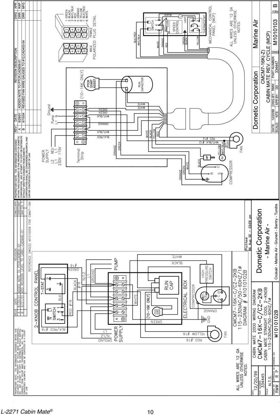
10 L-2271 Cabin Mate 10
11 L-2271 Cabin Mate 11
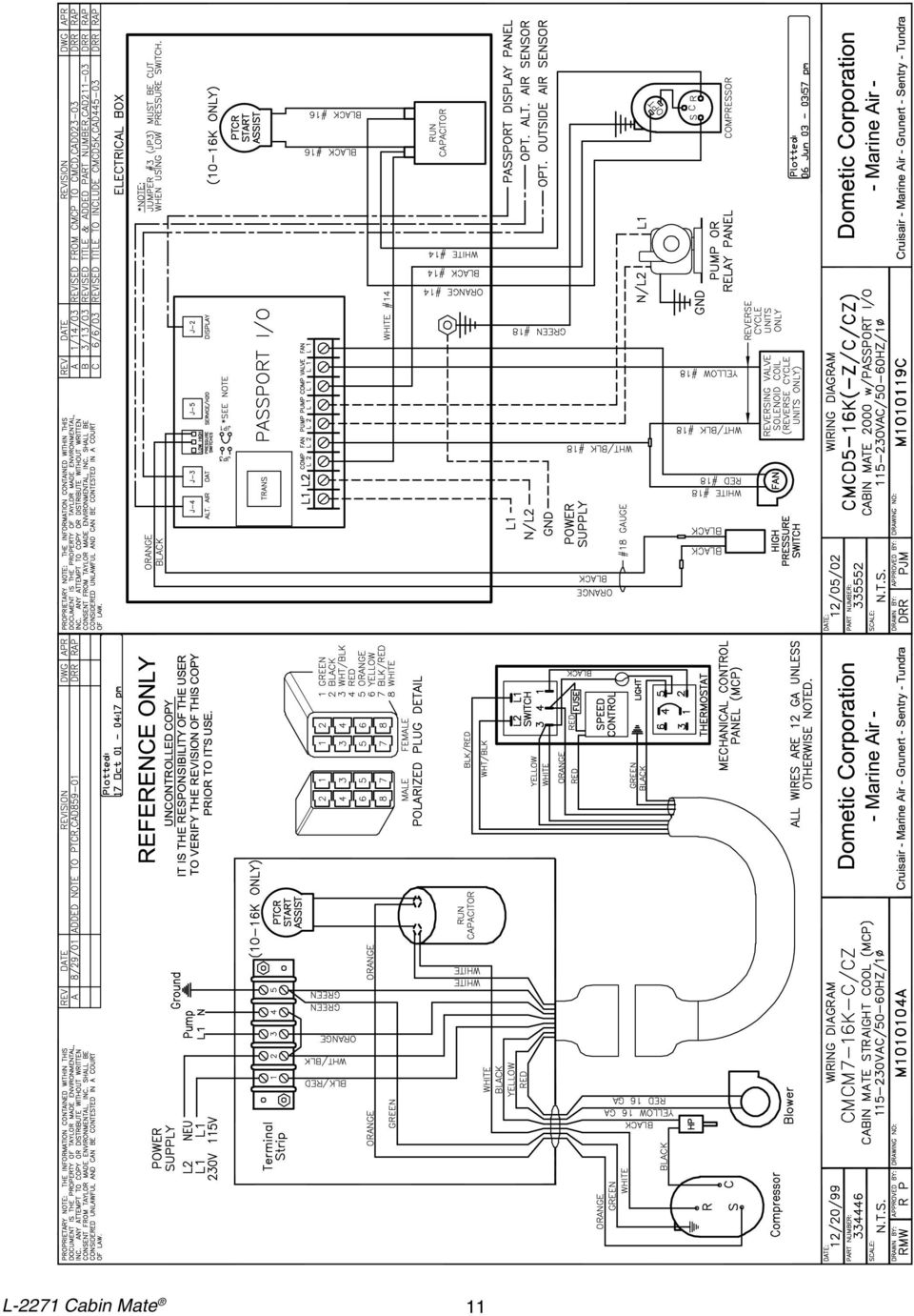
12 ELECTRICAL CONNECTIONS, GROUNDING AND BONDING & ABYC STANDARDS All a/c units have a terminal strip mounted either inside or outside the electric box. The terminal strip is labeled for proper connections of the electrical supply, ground wires and pump circuits. A wiring diagram is provided in the electrical box and in this manual. The wiring diagram in the electrical box supersedes the one in this manual. The correct size circuit breaker should be used to protect the system as specified on the a/c unit s data plate label. A minimum of 12 AWG boat cable should be used to supply power to the a/c unit and the seawater pump. All connections shall be made with ring or fork terminals. Turn off a/c power supply circuit breaker before opening electrical box. Each a/c unit installed requires its own dedicated circuit breaker. If there is only one a/c unit installed, the seawater pump does not require a circuit breaker; the wiring from the seawater pump is connected to the terminal strip at the electrical box. If two or more a/c units use the same seawater pump, the pump wires will be connected to a pump relay panel (PRP) which in turn has its own dedicated circuit breaker sized for the pump (20 amp max). Please see the wiring diagram furnished with the PRP (NOTE: PRP triac must have mounting screw installed in order to dissipate heat). Connections in the bilge below the waterline should use heat shrink type butt splices. Field wiring must comply with ABYC electrical codes. Power to the unit must be within the operating voltage range indicated on the data plate. Properly sized fuses or HACR circuit breakers must be installed for branch circuit protection. See data plate for maximum fuse/circuit breaker size (mfs) and minimum circuit ampacity (mca). All units must be effectively grounded to minimize the hazard of electrical shock and personal injury. The following are to be observed: 1. AC (alternating current) grounding (green wire) must be provided with the AC power conductors and connected to the ground terminal (marked GRND ) at the AC power input terminal block of the unit(s), per ABYC standard E-8, or equivalent. 2. Connections between the vessel s AC system grounding conductor (green wire) and the vessels DC (direct Current) negative or bonding system should be made as part of the vessel s wiring, per ABYC standard E9, or equivalent. 3. When servicing or replacing existing equipment that contains a chassis-mounted ground stud, the service person or installer must check the vessel s wiring for the existence of the connection required in item 2 above. ABYC standards are available from: American Boat and Yacht Council 3069 Solomon s Island Rd. Edgewater, MD Telephone: (410) The a/c unit must be connected to the vessel s bonding system to prevent corrosion due to stray electrical current or voltage. All pumps, metallic valves and fittings in the seawater circuit that are isolated from the a/c unit by PVC or rubber hoses must be individually bonded to the vessel s bonding system also. This will help eliminate any possibility of corrosion due to stray current or voltage. FAILURE TO PROPERLY GROUND AND BOND THE SYSTEM WILL VOID WARRANTY! MANUAL CONTROL PANELS (MCP) INSTALLATION The MCP should be located within cap tube length of the CABIN MATE unit. The cut out size for the 2 knob MCP is 2.5" wide by 4.5" tall. The 3 knob MCP is configured either vertically or horizontally. The cut out size is.2.5" by 7.0", see MCP for orientation. Once the cut out is made, carefully uncoil the copper cap tube with return air sensor (copper bulb) and route the control wires and cap tube through the hole and back to the unit using caution not to kink the cap tube. Mount the return air sensor into the clips provided on the evaporator coil. If the return air sensor cannot be mounted on the evaporator coil, mount it behind the return air grille. The sensor must be mounted in the return air stream. Make electrical connections according to the wiring diagrams. L-2271 Cabin Mate 12

13 INSTALLATION CHECKLIST (review prior to installation) Seawater cooling system: o Speed scoop located as far below the waterline and as close to the keel as possible o Shut off valve and speed scoop properly sealed and tight o Seawater pump at least one foot below waterline and securely mounted o Strainer mounted below pump with access to filter o Double/reversed stainless steel hose clamps on all hose connections o Teflon tape on all threaded connections o Hose runs uphill from speed scoop and seacock to strainer, pump and a/c unit, then downhill from a/c unit to overboard discharge o Water flowing freely from overboard discharge while pump is running Mounting o Not In engine room or bilge areas, must be sealed away from exhaust or fumes o Proper spacing allowed around unit for hose and duct connections and for serviceability o Attached to solid level platform with hold down clips provided o Condensate drain routed aft and down hill to a sealed sump (not bilge) o Blower rotated toward supply air grille Electrical o All butt connections on pump wire tightly crimped and heat shrunk o AC power source installed and grounded/bonded in accordance with ABYC standards o Control wires connected to terminal strip with fork or ring terminals o Circuit breakers sized according to specifications on the data plate label o Passport ll display cable is connected at both ends o Pump Relay Panel (if used) has a dedicated circuit breaker sized for the pump but not to exceed 20 amps maximum Grilles and Ducting o Supply air grille mounted as high as possible o Return air grille mounted as low and as close to the a/c unit as possible o Return air grille mounted away from bilge vapors or exhaust fumes o Ducting is pulled taut, straight, smooth and properly connected with no excess OPERATIONS CHECKLIST OPERATION o Ensure seawater intake ball valve is open o Turn on the a/c circuit breaker. If the seawater pump has its own circuit breaker, turn that on o Turn the system on o Set the desired cabin temperature (set point) o Check for a steady solid stream of water from the overboard discharge o Verify that there is steady airflow out of the supply air grille o If the unit does not appear to be operating properly, refer to troubleshooting guidelines Note:Do not turn the unit off and immediately turn it back on. Allow at least 30 seconds for refrigerant pressure equalization. L-2271 Cabin Mate 13

14 MCP OPERATION: 3-KNOB (3KB) & 2-KNOB (2KB) 1) Ensure seawater intake ball valve (seacock) is open. 2) Turn SYSTEM SWITCH control knob to OFF. 3) Turn on a/c circuit breaker. If the sea water pump has its own circuit breaker, turn that on too. 4) Turn the SYSTEM SWITCH control knob to FAN (2KB) or START (3KB), this energizes the fan and seawater pump (3KB, see note). Turn THERMOSTAT control knob to the coolest position by rotating it fully clockwise. If system has reverse cycle, turn knob counterclockwise for heat. 5) Turn FAN SPEED control knob to highest setting (3KB). 6) Verify that the fan is running and that there is steady airflow out of the supply air grille. 7) Turn the SYSTEM SWITCH to RUN, this will start the compressor and seawater pump (2KB, see note). The indicator light on the 3KB control will illuminate. 8) Check for a steady solid stream of seawater from the overboard discharge. 9) To set the thermostat, allow sufficient time for the unit to cool/heat the area to the desired temperature. When the area is sufficiently cooled/heated, turn the thermostat knob slowly toward the center position until it clicks once (the indicator light on the 3KB will turn off). The thermostat is now set to maintain a constant temperature. While heating, if the ambient temperature is less than 50 F (10 C), set the FAN SPEED control knob to low (3KB) for five to ten minutes until the unit begins to heat well, then increase the fan speed for more heat output. Note: The seawater pump comes on with the fan on the 3KB (switch set to START) and with the compressor on the 2KB (switch set to RUN). The thermostat on the MCP control panel serves to cycle the compressor on and off and provide an automatic changeover from cooling to heating (reverse cycle only) with a 3.5 F (6.3 C) differential. Rotating the thermostat to the left after it has been set for cooling will cause the unit to heat. If you rotate the thermostat to the right, the unit will cool. If the thermostat is left stationary after being set, the unit will cycle from cooling to neutral, or heating to neutral depending on the requirement. IMPORTANT NOTE: Reverse cycle units have a reversing valve that must be energized periodically to keep the internal parts moving freely. To accomplish this, switch the a/c into HEAT for a few seconds once a month. Note: Do not turn the unit off and immediately turn it back on. Wait at least 30 seconds for system refrigerant pressures to balance. L-2271 Cabin Mate 14
 Turn FAN SPEED control knob to highest setting (3KB). 6) Verify that the fan is running and that there is steady airflow out of the supply air grille.")
15 MAINTENANCE Seawater Strainer Insure that your pump receives adequate seawater flow by regularly cleaning the strainer basket. Periodically check the overboard discharge for a steady stream of water. Check seawater intake speed scoop for obstructions. Make sure hoses are not looped, kinked or crushed. Condenser Coil Cleaning Coils can become fouled over a period of time due to marine growth or scale build-up. This both obstructs water flow and prohibits proper heat transfer. To clean coils, using a chemical pump, flush with a 5% muriatic or hydrochloric acid and fresh water solution. Disconnect system hoses and check for fouling. Pump solution through coil (and hoses if need be) until clean. Rinse with fresh water and reconnect hoses. Follow manufacturer s safety guidelines for all cleaning solutions. Return Air Filters Check the return air filter about once a month and clean as necessary. To clean the filter, remove it from the unit, rinse with water, air dry and reinstall. Winterization There are several methods of winterization, some of which work better than others. The four various methods employed using a 50/50 non-polluting biodegradable anti-freeze/water solution are: 1. Pumping of anti-freeze solution into the overboard thru-hull fitting, and discharging through the intake thru-hull fitting, if the boat is out of water. If the boat is in the water then the thru-hull should be closed and the system drained then filled back to the unit outlet. 2. Use of the seawater pump to pump anti-freeze solution through the system and discharging through the overboard thru-hull fitting. Close seacock, remove hose from strainer discharge, raise hose above pump (so pump does not lose its prime) and pour in anti-freeze solution. Pump solution through system. The strainer and hose to seacock will also need to be drained of water. 3. Use of pressurized air injected at the overboard discharge fitting and the water being discharged through the seawater intake fitting. 4. Use of pressurized air to force water from the intake through the overboard discharge. Note: Collect all discharged liquids and recycle or dispose of in a proper manner. Any method that causes the anti-freeze solution to flow downward is the method of choice. By this means, the antifreeze solution will displace any water trapped and eliminate the possibility of freezing in hidden areas. In addition, since the seawater pump utilizes a magnetically driven impeller, the impeller should be removed from the wet end assembly, wiped with an alcohol solution, and stored in a warm, dry area until commissioning takes place. L-2271 Cabin Mate 15

16 GENERAL TROUBLESHOOTING Also see specific digital or mechanical control troubleshooting sections following these general guidelines. Fault: Will not start. 1. Air conditioning circuit breaker is off. Turn circuit breaker on at ship s panel. 2. Control is not turned on. See mechanical control section of this manual for MCP controls, or see the digital control manual for Elite or Passport I/O controls. 3. Wrong wiring at terminal strip. Check wiring diagram and correct if necessary. 4. Push-on butt connectors became disconnected during installation. Disconnect power supply and open electric box, check wiring diagram, correct if necessary 5. Input line voltage is insufficient. Check power source (shore/generator) for proper voltage. Check wiring and terminals for proper sizes and connections. Verify with a voltmeter that the power at the unit is the same as the power source. Fault: Fan is not running. Check specific control troubleshooting section. Fault: No cooling or heating. 1. Temperature set point is satisfied. Lower or raise set point. 2. Obstructed seawater flow. Clean seawater strainer. Check for obstructions at speed scoop thru-hull inlet. Check for a good steady flow from the overboard discharge. 3. Seawater pump may be air-locked. Remove hose from pump discharge to purge air from line. 4. Loss refrigerant gas. Check air conditioning unit for refrigerant oil leakage, call service technician. 5. Seawater temperature too high for cooling or too low for heating. Seawater temperature will directly affect air conditioning unit s efficiency. This air conditioning unit can effectively cool your boat in water temperature up to 90 F (32.2 C) and heat (if reverse cycle option is installed) in water as low as 40 F (4.4 C). 6. Fan coil is iced (in cooling). Check your specific control troubleshooting section. 7. Fan is not running. Check your specific control troubleshooting section. 8. Seawater plumbing is air-locked. Ensure that seawater plumbing is installed per the guidelines in this manual. L-2271 Cabin Mate 16

17 9. Digital control is programmed for Cool or Heat only, or mechanical control thermostat is rotated too far towards either Cooler or Warmer setting. See digital control manual for reprogramming or see mechanical control operation section in this manual. 10. High pressure switch open (in cooling) due to improper seawater flow. Strainer or intake may be plugged, seacock may be closed, check seawater hose for kinks or collapses. Verify pump operation. Check the pump circuit breaker if applicable. 11. High pressure switch open (in heating) due to improper airflow. Remove any obstructions in return air stream. Clean return air filter and grille. Check for crushed or restricted ducting, ducting must be as straight, smooth and taut as possible. 12. High-pressure switch is open in heating mode. System may cycle on high-pressure if seawater temperature is above 55 F (12.8 C). 13. Compressor s thermal overload is open due to either of the above reasons. Compressor needs to cool down. Turn system off for a while (it may take up to three hours to reset thermal overload). Fault: No heating. 1. Unit is cool only, or if reverse cycle, reversing valve may be stuck. Tap reversing valve lightly with rubber mallet while unit is in heat mode. Call for service if that does not correct the problem. Fault: Low airflow. 1. Airflow is blocked. Remove any obstructions in return air stream. Clean return air filter and grille. Check for crushed or restricted ducting, ducting must be as straight, smooth and taut as possible. 2. Fan coil is iced. See below. Fault: Fan coil is iced. 1. Thermostat set point is too low. Raise set point. 2. Improper airflow. Remove any obstructions in return air stream. Clean return air filter and grille. Check for crushed or restricted ducting, must be as straight, smooth and taut as possible. See the Digital Controls Troubleshooting section below for reprogramming options. 3. Supply air is short-cycling. Redirect supply air so that it is not blowing into the return air stream. Seal any air leaks on duct. 4. Humidity level too high. Close hatches and doors. 5. When all else fails. Switch air conditining to heat until ice melts or use hair dryer to melt. L-2271 Cabin Mate 17
 due to improper airflow. Remove any obstructions in return air stream. Clean return air filter and grille.")
18 Fault: Water coil is iced in the heating mode. 1. Seawater temperature is below 40 F 4.4 C. Shut down system to prevent damage to condenser. Allow coil to defrost. Fault: System runs continuously. 1. Set point temperature is improperly set: too low for cooling or too high for heating. Raise or lower set point. 2. Porthole or hatches open. Close all port holes and hatches. 3. Seawater temperature too high for cooling or to low for heating. Seawater temperature will directly affect the a/c unit s efficiency. This a/c unit can effectively cool your boat in water temperatures up to 90 F (32.3 C) and heat (if reverse cycle option is installed) in water as low as 40 F (4.4 C). 4. Improper air sensor location. Check your specific control troubleshooting section. Digital Controls Troubleshooting Fault: Digital display panel is not lit pin display cable plugs are not making contact (unplugged, dirty, bent, or broken pins). With POWER OFF at the circuit breaker, remove connector and inspect. If damaged, replace connector or entire display cable. Fault: Fan is not running or runs continuously. 1. Digital control is programmed for either fan cycling with compressor or continuous fan operation. Elite Control: Press and hold the fan button for five seconds to change to con so fan will stay on continuously or to CYC so the fan cycles with the compressor. Passport I/O Control: Reprogram parameter P-14. Note: After the compressor cycles off, the fan will continue to run for two minutes in Cool Mode and four minutes in Heat Mode regardless of parameter setting. Fault: Fan is not running but the compressor is. 1. Failed triac on Passport I/O circuit board. Send for repair or call local service technician (see distributor listing). L-2271 Cabin Mate 18
 and heat (if reverse cycle option is installed) in water as low as 40 F (4.4 C). 4. Improper air sensor location. Check your specific control troubleshooting section.")
19 Fault: Fan runs continuously although it is set to cycle with compressor. 1. Failed triac on Passport I/O circuit board. Send for repair or call local service technician (see distributor listing). Fault: No cooling or heating. 1. Digital control programmed for heat or cool only. Elite Control: Press and release the Mode button (bottom right corner of display) until the desired mode LED is lit. Passport I/O Control: Reprogram parameter P HPF or LPF is displayed. See below. Fault: No heat. 1. Digital Control may be set to Electric Heat, not Reverse Cycle. Elite Control: Reprogram parameter P-13 Passport I/O Control: Reprogram parameter P-15 Fault: Unit switches to heat while in cool mode. 1. De-icing feature enabled due to coil icing up. Elite Control: Reprogram parameter P-7 Passport I/O Control: Reprogram parameter P-8 Fault: Fan coil is iced. 1. Improper airflow. See the General Troubleshooting section above first, before reprogramming digital control. Reprogram parameter P-7 for Elite or P-8 for Passport I/O. If de-icing cycle does not melt ice, switch air conditioning unit to heat until ice melts or use hair dryer to melt ice. If problem persists, reprogram Low Fan Speed Limit for maximum value. Set P-2 to 55 for Elite or set P-3 to 64 for Passport I/O. Fault: System runs continuously. 1. Improper air sensor location. Verify display head location with criteria found in the control manual. Install alternate air sensor if necessary. L-2271 Cabin Mate 19

20 Fault: HPF is displayed. 1. High-pressure switch is open (in cooling) due to improper seawater flow. Strainer or intake may be plugged, seacock may be closed, check seawater hose for kinks or collapses. Verify pump operation; check pump circuit breaker if applicable. 2. High-pressure switch open (in heating) due to improper airflow. Remove obstructions in return air stream. Clean air filter and grille. Check for crushed or restricted ducting, ducting must be as straight, smooth and taut as possible. If problem persists, reprogram Low Fan Speed Limit for maximum value. Set P-2 to 55 for Elite or set P-3 to 64 for Passport I/O. And, set the Reverse Fan Speeds During Heating Mode parameter to ref (P-12 for Elite or P-13 for Passport I/O), or manually set fan speed to high. Fault: LPF is displayed. 1. Low-pressure switch is open due to low seawater and/or low return air temperatures. Try restarting the a/c unit; the optional low-pressure switch has a ten minute shutdown time delay that may be in affect. 2. Low pressure switch is open due to loss of refrigerant. Check air conditioning unit for refrigerant oil leakage, call service technician. Fault: ASF is displayed. 1. Indicates failed faceplate air sensor, alternate air sensor or display cable. Unplug alternate air sensor if installed or plug in alternate air sensor if not installed. Try another display cable. 2. Damaged jack/socket in display head or on circuit board. Visually check to see that pins inside socket are not bent or corroded. Repair or replace display or circuit board if needed. Fault: PLF is displayed (Elite Digital Control only). 1. Indicates that seawater flow through the condenser coil is insufficient. Check for adequate seawater flow. Verify pump operation. Inspect the condenser coil; it may need cleaning (see MAINTENANCE section). Sensor may be faulty, replace if necessary. Call for service technician. L-2271 Cabin Mate 20

21 Fault: Fan is not running. MCP Mechanical Control Panel 1. 3-Knob MCP system switch is not set properly. Set MCP system switch to START for fan only or RUN for cooling and heating (if reverse cycle) Knob MCP fuse blown. Replace 10-amp fuse behind MCP panel knob MCP system switch is not set properly. Set system switch to FAN for fan only or COOL for cooling and heating. 4. Wire became disconnected or loosened during installation. Reconnect or tighten, verify with wring diagram in this manual. Fault: System runs continuously. 1. Improper MCP air sensor location. Verify return air sensing bulb location with criteria found in this manual. Fault: No cooling or heating. 1. High-pressure switch is open (in cooling) due to improper seawater flow. Strainer or intake may be plugged, seacock may be closed, check seawater hose for kinks or collapses. Verify pump operation. Check the pump circuit breaker if applicable. 2. High-pressure switch open (in heating) due to improper airflow. Remove any obstructions in return air stream. Clean return air filter and grille. Check for crushed or restricted ducting, ducting must be as straight, smooth and taut as possible. 3. MCP is not set properly. 3-knob should be set to RUN. 2-knob should be set to COOL. L-2271 Cabin Mate 21
22 MANUFACTURERS LIMITED WARRANTY AGREEMENT The following warranty is extended to cover marine air conditioners manufactured or supplied by Dometic Environmental Corporation, and is subject to qualifications indicated. Dometic warrants for the periods set forth below that products manufactured or supplied by it will be free from defects in workmanship and material, provided such products are installed, operated, and maintained in accordance with Dometic s written instruction. ALL IMPLIED WARRANTIES INCLUDING MERCHANTABILITY AND FITNESS FOR A PARTICULAR PURPOSE, ARE LIMITED TO THE TERMS AND PERIODS OF WARRANTY SET FORTH BELOW AND, TO THE EXTENT PERMITTED BY LAW, ANY AND ALL IMPLIED WARRANTIES ARE EXCLUDED. Warranty with the Elite or Passport I/O digital controls (Coverage applies to units manufactured on or after 03/01/ 03 and applies only to units equipped with Elite or Passport I/O digital controls at the Dometic factory.): Components comprising of the Passport I/O circuit boards, Elite or Passport I/O digital displays, and associated cables are warranted for a period of three (3) years from the date of installation, but not to exceed four (4) years from the date of manufacture at the Dometic factory. All other components comprising a complete system (excluding pumps and pump relay panels) on a new installation are warranted for a period of two (2) years from the date of installation, but not to exceed three (3) years from the date of manufacture at the Dometic factory. Pumps and pump relay panels are warranted for a period of one (1) year from the date of installation, but not to exceed two (2) years from the date of purchase. OEM installed equipment warranties begin with the purchase of the vessel, not from the date of installation. Warranty with MCP (Mechanical Control Panel) control: Components comprising a complete system on a new installation are warranted for a period of one (1) year from the date of installation, but not to exceed two (2) years from the date of manufacture at the Dometic factory. OEM installed equipment warranties begin with the purchase of the vessel, not from the date of installation. In addition, Dometic will pay labor costs and travel as outlined in its Schedule of Limited Warranty Allowances for removal and reinstallation of such components for a period of one (1) year from the date of installation, but not to exceed two (2) years from the date of manufacture at the Dometic factory. OEM installed equipment warranties begin with the purchase of the vessel, not from the date of installation. Warranty will be paid in accordance with our established schedule of allowances. Compensation for warranty repairs is only made to Dometic authorized service companies. Dometic will repair, or replace at its option, components found to be defective due to faulty materials or workmanship, when such components, examined by an authorized service dealer or a factory service representative, are found to have a defect for which the company is responsible. Refer to Manufacturer s Limited Warranty Policy for complete coverage and exclusions. Replacement components are warranted for the duration of the remaining warranty period in effect on the original component. In the event that a unit has to be returned to the factory, it must be properly packaged to prevent shipping damages. If packaging is not available, Dometic will provide it at no charge. The warranty may be voided on any piece of equipment or component that is damaged due to improper packaging. This limited warranty is extended in lieu of all other warranties, agreements or obligations, expressed or implied, concerning Dometic s components. This warranty is extended only to the original purchaser and is not transferable. This warranty shall be governed by the laws of the State of Florida and gives the original first end user definite legal rights. This warranty does not cover damages incidental and/or consequential to the failure of Dometic s equipment including but not limited to; normal wear, accident, misuse, abuse, negligence, improper installation, lack of reasonable and necessary maintenance, alteration, civil disturbance or acts of God. No person or dealer is authorized to extend any other warranties or to assume any other liabilities on Dometic s behalf, unless made or assumed in writing by an officer of Dometic. L-2271 Cabin Mate 22
23 Marine Air Worldwide Service Dealer Locator The majority of the service listings displayed for the United States are key members of the national Marine Air distributor network. If you need service, please contact the closest company shown. In most cases they will direct you to a local dealer or service port. We have over 500 Marine Air dealers in the national Marine Air network, and one should be convenient to you. The international companies listed are, in many cases, distributors and are capable of managing the majority of service requests for the countries listed. In some cases they will refer you to a local dealer. You may also contact us directly via the web site or call us in the US at (954) For a complete and up-to-date Dealer locator list, please visit our website at USA Alabama AER Marine Supply Seabrook, TX, USA (281) (281) [email protected] Alaska American Marine Contractors Seattle, WA, USA (206) (206) [email protected] Arizona Southern California Marine Enterprises San Diego, CA, USA [email protected] Arkansas AER Marine Supply Seabrook, TX, USA (281) (281) [email protected] California Southern California Marine Enterprises San Diego, CA, USA [email protected] Colorado AER Marine Supply Seabrook, TX, USA (281) (281) [email protected] Ocean Options Connecticut Tiverton, RI, USA (401) (401) [email protected] Delaware Ocean Options - Mid Atlantic Annapolis, MD, USA (410) (410) [email protected] Florida (North) Beard Marine Savannah - Distributor Savannah, GA, USA (912) (912) [email protected] Florida (South) ARW Maritime - Dealer Ft. Lauderdale, Florida, USA Fort Lauderdale (954) (954) [email protected] Beard Marine - Ft. Lauderdale - Dealer Ft. Lauderdale, Florida, USA Fort Lauderdale (954) (954) [email protected] Beard Marine of the Palm Beaches - Dealer Riviera Beach, Florida, USA Riviera Beach (561) (561) [email protected] Cable Marine - Dealer Ft. Lauderdale, Florida, USA Fort Lauderdale (954) (954) Comfort Marine - Dealer Ft. Lauderdale, FL, USA Ft. Lauderdale (954) (954) Cowherd Marine - Dealer Lake Park, Florida, USA West Palm Beach (561) (561) Dometic Corporation-Environmental Systems, Distributor Pompano Beach, FL, USA South Florida (954) (954) [email protected] Edd Helms Marine Air Conditioning - Dealer Miami, Florida, USA Ft. Lauderdale, Miami [email protected] IYS Marine - Dealer Florida (South) Pinellas Park, Florida, USA Tampa-St Petersburg (727) (727) [email protected] Jim's Marine A/C - Dealer Port Charlotte, Florida, USA Port Charlotte (941) Marine Air Conditioning - Dealer Ft. Pierce, Florida, USA Port St. Lucie (772) (772) Masters Marine Center, Inc. - Dealer Miami, Florida, USA Miami (305) (305) Neptune Air Corporation - Dealer Ft. Lauderdale, Florida, USA Fort Lauderdale (954) (954) Palm Beach Aqua Air - Dealer West Palm Beach, Florida, USA West Palm Beach (561) (561) Sea Air Land Technologies - Dealer Marathon, Florida, USA Florida Keys (305) (305) [email protected] Sea Breeze Marine - Dealer Lighthouse Point, Florida, USA Lighthouse Point (954) (561) Tropica Boats & Marine, Inc. - Dealer Fort Myers, Florida, USA Fort Myers (239) (239) [email protected] Ty Cobb Services, Inc. - Dealer Sebastian, Florida, USA Sebastian (772) (772) L-2205M Revised:
24 Georgia Beard Marine Savannah - Distributor Savannah, GA, USA (912) (912) [email protected] Hawaii Southern California Marine Enterprises San Diego, CA, USA [email protected] Idaho American Marine Contractors Seattle, WA, USA (206) (206) [email protected] Illinois Midwest Marine Supply St. Clair Shores, MI, USA (586) (586) Indiana Midwest Marine Supply St. Clair Shores, MI, USA (586) (586) Iowa Midwest Marine Supply St. Clair Shores, MI, USA (586) (586) AER Marine Supply Kansas Seabrook, TX, USA (281) (281) [email protected] Kentucky Midwest Marine Supply St. Clair Shores, MI, USA (586) (586) AER Marine Supply Ocean Options Louisiana Seabrook, TX, USA (281) (281) [email protected] Maine Tiverton, RI, USA (401) (401) [email protected] Maryland Ocean Options - Mid Atlantic Annapolis, MD, USA (410) (410) [email protected] Massachusetts Ocean Options Tiverton, RI, USA (401) (401) [email protected] Michigan Midwest Marine Supply St. Clair Shores, MI, USA (586) (586) Minnesota Midwest Marine Supply St. Clair Shores, MI, USA (586) (586) AER Marine Supply Mississippi Seabrook, TX, USA (281) (281) [email protected] AER Marine Supply Missouri Seabrook, TX, USA (281) (281) [email protected] Montana American Marine Contractors Seattle, WA, USA (206) (206) [email protected] AER Marine Supply Ocean Options Nevada Seabrook, TX, USA (281) (281) [email protected] New Hampshire Tiverton, RI, USA (401) (401) [email protected] New Jersey Marine Specialists Ronkonkoma, NY, USA New York, New Jersey (631) (631) [email protected] New Mexico AER Marine Supply Seabrook, TX, USA (281) (281) [email protected] Marine Specialists New York Ronkonkoma, NY, USA New York, New Jersey (631) (631) [email protected] North Carolina Beard Marine Savannah - Distributor Savannah, GA, USA (912) (912) [email protected] North Dakota Midwest Marine Supply St. Clair Shores, MI, USA (586) (586) Ohio Midwest Marine Supply St. Clair Shores, MI, USA (586) (586) AER Marine Supply Oklahoma Seabrook, TX, USA (281) (281) [email protected] Oregon American Marine Contractors Seattle, WA, USA (206) (206) [email protected] Pennsylvania Ocean Options - Mid Atlantic Annapolis, MD, USA (410) (410) [email protected] Rhode Island Ocean Options Tiverton, RI, USA (401) (401) [email protected] South Carolina Beard Marine Savannah - Distributor Savannah, GA, USA (912) (912) [email protected] South Dakota Midwest Marine Supply St. Clair Shores, MI, USA (586) (586) Tennessee Beard Marine Savannah - Distributor Savannah, GA, USA (912) (912) [email protected] Texas AER Marine Supply Seabrook, TX, USA (281) (281) [email protected] L-2205M Revised:
25 AER Marine Supply Ocean Options Utah Seabrook, TX, USA (281) (281) Vermont Tiverton, RI, USA (401) (401) Virginia Ocean Options - Mid Atlantic Annapolis, MD, USA (410) (410) [email protected] Washington American Marine Contractors Seattle, WA, USA (206) (206) [email protected] West Virginia Ocean Options - Mid Atlantic Annapolis, MD, USA (410) (410) [email protected] Wisconsin Midwest Marine Supply St. Clair Shores, MI, USA (586) (586) Wyoming American Marine Contractors Antigua Seattle, WA, USA (206) (206) [email protected] Aboard Refrigeration Argentina, Antigua, West Indies (268) (419) [email protected] Baron SRL San Fernando, Buenos Aires, Argentina (54) (54) [email protected] Australia Seairland Systems, Inc. Brisbane, Queensland, Australia (61) (61) [email protected] Austria Dometic Marine Italy, Sales Company Milano, Italy [email protected] Bahamas Freezing Point, Ltd. Nassau, Bahamas Nassau (242) (242) [email protected] Bahrain Mantech Brazil Dubai, United Arab Emirates (971) (971) Marine Express Sao Paulo, Brazil [email protected] British Virgin Islands BVI Marine Management Roadtown, Tortola, British Virgin Islands (284) (284) C & G Refrigeration Canada, Tortola, British Virgin Islands (284) British Columbia American Marine Contractors Seattle, WA, USA (206) (206) [email protected] Queensville Ontario Northland Supply Company Queensville, Ontario, Canada (905) (905) [email protected] Woodard and Company - Manufacturer's Rep. Kimpex, Inc. Concord, Ontario, Canada All Canadian Provinces except BC (905) (905) [email protected] Quebec Drummondville, Quebec, Canada Drummondville, Quebec (705) (705) [email protected] Caribbean Islands Aboard Refrigeration, Antigua, West Indies (268) (419) [email protected] BVI Marine Management Roadtown, Tortola, British Virgin Islands (284) (284) C & G Refrigeration, Tortola, British Virgin Islands (284) Caraibes Distribution Marin, Martinique, French West Indies Centro Cruisair de Puerto Rico San Turce, Puerto Rico [email protected] Cool-Tech Air Condition Fajardo, Puerto Rico (787) (787) [email protected] Enertech N.V. Simpson Bay, St. Maarten/St. Martin, Netherland Antilles (USA) [email protected] Freezing Point, Ltd. Nassau, Bahamas Nassau May Day Marine (242) (242) [email protected] San Juan, Puerto Rico Nau-T-Kol Marine Refrigeration Chaguaramas, Trinidad [email protected] Reefco, Inc., St. Thomas, US Virgin Islands (340) (340) [email protected] Regis Electronics (St Lucia) LTD. St. Lucia, West Indies [email protected] Sun Cool Air Conditioning Carolina, Puerto Rico, Puerto Rico Carolin (787) (787) [email protected] L-2205M Revised:
26 China Flash Marine Trading Pte.Ltd. Costa Rica Gato Frío Shanghai, China (86 21) (86 21) Playa Jaco, Costa Rica Costa Rica, Panama Croatia Dometic Marine Italy, Sales Company Milano, Italy Cyprus Dometic Marine - United Kingdom, Sales Company Poole, Dorset, England 44 (0) (0) [email protected] Dominican Republic May Day Marine Ecuador San Juan, Puerto Rico Quasar Nautica, S.A. Egypt Engineering Air France P.O. Box , Quito, Ecuador (593) /997 (593) Abasia, Cairo, Eygpt Dometic Marine France, Sales Company Plailly, France Cell: 0033 (0) (0) [email protected] PolyMarine Distribution (C/O Occas Marine) Le Cannet, Rocheville, France [email protected] French West Indies Caraibes Distribution Marin, Martinique, French West Indies Greece Dometic Marine - United Kingdom, Sales Company Poole, Dorset, England 44 (0) (0) [email protected] Athens Aegean Diesel Electric Ltd. Athens, Piraeus, Greece Athens [email protected] Hong Kong Piercey Marine Limited Italy Sai Kung, NT, Hong Kong (852) (852) [email protected] Condaria 87 SRL Nova Milanese (MI), Italy Dometic Marine Italy, Sales Company Milano, Italy [email protected] Japan Tominaga & Company, Ltd. Osaka, Japan [email protected] Kuwait Mantech Malta Dubai, United Arab Emirates (971) (971) Dometic Marine - United Kingdom, Sales Company Poole, Dorset, England 44 (0) (0) [email protected] Inmartech Ltd. Mexico Swieqi, STJ 04, Malta Southern California Marine Enterprises San Diego, CA, USA [email protected] Netherlands Eberca, Netherlands [email protected] Heinen & Hopman Eng. Bv. Spakenburg, Netherlands (31) (0) (31) (0) [email protected] Netherlands Antilles Enertech N.V. Simpson Bay, St. Maarten/St. Martin, Netherland Antilles (USA) [email protected] New Zealand Whiting Power Systems 192 Herne Bay, Auckland, New Zealand [email protected] Oman Mantech Panama Gato Frío Dubai, United Arab Emirates (971) (971) Playa Jaco, Costa Rica Costa Rica, Panama [email protected] Productos Marine Air La Chorrea, Panama Panama [email protected] Portugal PowerCool Lda Portimao, Portugal Portugal [email protected] Puerto Rico Centro Cruisair de Puerto Rico San Turce, Puerto Rico [email protected] Cool-Tech Air Condition Fajardo, Puerto Rico (787) (787) [email protected] L-2205M Revised:
27 May Day Marine San Juan, Puerto Rico Sun Cool Air Conditioning Qatar Mantech Russia Carolina, Puerto Rico, Puerto Rico Carolin (787) (787) Dubai, United Arab Emirates (971) (971) Standarte Starbeevo, Moscow region, Russia [email protected] Saudi Arabia Mantech Scandinavia Dubai, United Arab Emirates (971) (971) Dometic Marine Nordic Sales, Sales Company Halmstad, Sweden [email protected] Singapore Tritex Equipment PTE, Ltd., Singapore Singapore (65) (65) [email protected] Slovenia Dometic Marine Italy, Sales Company Milano, Italy [email protected] South Africa C-Dynamics cc Cape Town, South Africa [email protected] Spain Acastimar Tarragona, Spain [email protected] Dometic Marine France, Sales Company Plailly, France Cell: 0033 (0) (0) [email protected] Techno Electronica Naval, S.A. Barcelona, Spain 34 (93) (93) [email protected] Sri Lanka G&M Enterprises Borella-Colombo 8, Sri Lanka [email protected] Sweden Dometic Marine Nordic Sales, Sales Company Halmstad, Sweden [email protected] Thailand Thai Kolon Co. Ltd. Bangkok, Thailand (10 lines) [email protected] Trinidad & Tobago Nau-T-Kol Marine Refrigeration Chaguaramas, Trinidad [email protected] Turkey Dometic Marine - United Kingdom, Sales Company Poole, Dorset, England 44 (0) (0) [email protected] Egemar Muhendiscik Ltd. Tuzla, Istanbul, Turkey [email protected] U.S. Virgin Islands Reefco, Inc., St. Thomas, US Virgin Islands (340) (340) [email protected] Ukraine Standarte Starbeevo, Moscow region, Russia [email protected] United Arab Emirates Mantech Dubai, United Arab Emirates (971) (971) United Kingdom Dometic Marine - United Kingdom, Sales Company Poole, Dorset, England 44 (0) (0) [email protected] Uruguay Baron SRL San Fernando, Buenos Aires, Argentina (54) (54) [email protected] Venezuela Rich Marine Center West Indies Complejo Turistico El Morro, Venezuela, South America (58) (58) [email protected] Aboard Refrigeration, Antigua, West Indies (268) (419) [email protected] Regis Electronics (St Lucia) LTD. St. Lucia, West Indies [email protected] Yemen Mantech Dubai, United Arab Emirates (971) (971) L-2205M Revised:
28 For service of product purchased through a catalog or chain store, please call our Ocean Marketing Customer Service Hot Line: (888) Dometic Environmental Corporation 2000 N. Andrews Ave. Ext. Pompano Beach, FL USA Facsimile: For Sales and Service Calls within Europe and the Middle East, please contact +44 (0) Website: [email protected] L-2271
Dometic turbo Direct expansion
 Dometic turbo Direct expansion AIR CONDITIONING SYSTEMs installation manual Dometic Environmental Corporation Rev. 20140321 L-2484 DOMETIC TURBO DX AC INSTALLATION MANUAL CONTENTS Introduction 4 Installation
FEEL COOL FAST. MARINE AIR CONDITIONER Installation & Operation Manual
 FEEL COOL FAST MARINE AIR CONDITIONER Installation & Operation Manual 6/2012 Table of Contents INTRODUCTION... 4 PACKAGED COMPONENTS... 5 OVERVIEW... 5 INSTALLATION... 6 Unpacking and Inspection... 6
Operation, Installation & Maintenance
 Operation, Installation & Maintenance 7/02 L-2168 PREFACE Congratulations on the purchase of your Marine Air Systems VECTOR COMPACT air conditioner. No matter which of the following features was the reason
Oil and Coolant Circulating Heating System. Model - OCSM
 Oil and Coolant Circulating Heating System Model - OCSM Installation & Operation Manual 216280-000 REV 2 Identifying Your System The HOTSTART heating system is designed to heat fluids for use in marine
Roof Top Air Conditioner INSTALLATION AND OPERATING INSTRUCTIONS
 Roof Top Air Conditioner INSTALLATION AND OPERATING INSTRUCTIONS Ducted System RECORD THIS UNIT INFORMATION FOR FUTURE REFERENCE: Model Number: Serial Number: Date Purchased: This manual must be read and
Portable Air Conditioner. OWNER S MANUAL Read these instructions before use. Model: MF08CESWW. Voltage rating: 115V~60Hz Power rating : 800W
 MODE ALARM Portable Air Conditioner OWNER S MANUAL Read these instructions before use 8 Model: MF08CESWW Voltage rating: 115V~60Hz Power rating : 800W Customer Support : 1-800-474-2147 For product inquiries
Portable Air Conditioner. OWNER S MANUAL Read these instructions before use. Model: MN12CES / MN10CESWW
 Portable Air Conditioner OWNER S MANUAL Read these instructions before use 8 Model: MN12CES / MN10CESWW Voltage rating: 120V~60Hz Power rating : 1100W (MN12CES) Power rating : 900W (MN10CESWW) Customer
Portable Air Conditioner. OWNER S MANUAL Read these instructions before use. Model: MM14CCS. Voltage rating: 115V~60Hz Power rating : 1400W
 Portable Air Conditioner OWNER S MANUAL Read these instructions before use Model: MM14CCS Customer Support : 1-800-474-2147 Voltage rating: 115V~60Hz Power rating : 1400W For product inquiries or support
EnviroComfort (ECD) INSTALLATION MANUAL. Dometic Marine Rev. 20140401 L-3036 English. EnviroComfort Kit
 INSTALLATION MANUAL. Dometic Marine Rev. 20140401 L-3036 English. EnviroComfort Kit") EnviroComfort (ECD) INSTALLATION MANUAL EnviroComfort Kit Dometic Marine Rev. 20140401 L-3036 English COPYRIGHT 2008-2014 Dometic Marine. All Rights Reserved. No part of this publication may be reproduced,
EnviroComfort (ECD) INSTALLATION MANUAL EnviroComfort Kit Dometic Marine Rev. 20140401 L-3036 English COPYRIGHT 2008-2014 Dometic Marine. All Rights Reserved. No part of this publication may be reproduced,
Ceiling Mount Air Handler Manual
 www.surna.com 303.993.5271 Ceiling Mount Air Handler Manual Models: CMAH12, CMAH18, CMAH24, CMAH30, CMAH36, CMAH48, CMAH60 Revised: September 2014 Table of Contents Warranty Information 4 Limited Warranty
Portable Air Conditioner
 Portable Air Conditioner Owner's Manual Model:3 in 1 12,000 Btu/h Series 3 Please read this owner s manual carefully before operation and retain it for future reference. CONTENTS 1. SUMMARY...1 2. PORTABLE
INSTALLATION INSTRUCTIONS Fan Coil Replacement Coil Kit EBX & EBXX
 Fan Coil Replacement Coil Kit EBX & EBXX These instructions must be read and understood completely before attempting installation. These instructions covers the installation of replacement coil kit into
Miami Heat Pump HP Series Installation Guide
 CAUTION- THIS UNIT IS FOR INDOOR USE ONLY!! WARNING BEFORE ANY INSTALLATION OR MAINTANCE IS STARTED PLEASE READ COMPLETE INSTLLATION GUIDE. INSTALLATION START-UP AND SERVICE INSTRUCTION- The HP Water Source
BUILT-IN DISHWASHER INSTALLATION INSTRUCTIONS
 BUILT-IN DISHWASHER INSTALLATION INSTRUCTIONS PLEASE READ COMPLETE INSTRUCTIONS BEFORE YOU BEGIN LEAVE INSTALLATION INSTRUCTIONS AND USER'S GUIDE WITH OWNER ALL ELECTRIC WIRING AND PLUMBING MUST BE DONE
mcw chiller Installation, Operation & Maintenance Manual for MCW Chillers Using the DDC Digital Diagnostic Control L-2164 Rev.
 mcw chiller Installation, Operation & Maintenance Manual for MCW Chillers Using the DDC Digital Diagnostic Control L-2164 Rev. 20140404 Preface Congratulations on the purchase of your air conditioning
DX Modulating A/C System
 DX Modulating A/C System INSTALLATION OPERATION For DX Modulating SMX II Control Systems using SMXII and SMXir displays Revised: 20140404 L-0952 Part Number: LP-28 Table of Contents Modulating A/C Systems
Portable Air Conditioner. OWNER S MANUAL Read these instructions before use. Model: MM14CHCSCS
 Portable Air Conditioner OWNER S MANUAL Read these instructions before use Model: MM14CHCSCS Voltage rating: 120V~60Hz Power rating : 1400W(Cooling) Power rating : 1350W(Heating) Customer Support : 1-800-474-21477
OWNER S MANUAL FORCE 10 MARINE COMPANY 23080 HAMILTON ROAD RICHMOND, BC CANADA V6V 1C9 TEL: (604) 522-0233 FAX: (604) 522-9608
 522-0233 FAX: (604) 522-9608") Electric Water Heater OWNER S MANUAL FORCE 10 MARINE COMPANY 23080 HAMILTON ROAD RICHMOND, BC CANADA V6V 1C9 TEL: (604) 522-0233 FAX: (604) 522-9608 If your water Heater is Damaged or you have questions
Electric Water Heater OWNER S MANUAL FORCE 10 MARINE COMPANY 23080 HAMILTON ROAD RICHMOND, BC CANADA V6V 1C9 TEL: (604) 522-0233 FAX: (604) 522-9608 If your water Heater is Damaged or you have questions
DTM04 TANK MONITOR DTM08 TANK MONITOR Dtm12 TANK MONITOR. Installation and Operation Manual
 DTM04 TANK MONITOR DTM08 TANK MONITOR Dtm12 TANK MONITOR Installation and Operation Manual 1 ENGLISH Safety Instructions 2 Features 2-3 Specifications 3 Installation 4-5 Wiring Diagrams 6-7 Warranty 8
543-0032-00, 943-0032-00. User s Manual
 543-0032-00, 943-0032-00 User s Manual 1 Comfort Alert Diagnostics Faster Service And Improved Accuracy The Comfort Alert diagnostics module is a breakthrough innovation for troubleshooting heat pump and
Service manual. Website: www.andico.com.au CAUTION - BEFORE SERVICING THE UNIT, READ THE SAFETY - PRECAUTIONS IN THIS MANUAL.
 Website: www.andico.com.au Service manual CAUTION - BEFORE SERVICING THE UNIT, READ THE SAFETY - PRECAUTIONS IN THIS MANUAL. - ONLY FOR AUTHORISED SERVICE PERSONNEL. MODELS: MPK1-09CR-QB8 MPK1-12ER-QB6
S33 Sump Pump INSTRUCTIONS AND SERVICE MANUAL VERTICAL FLOAT SWITCH S33V1 & S33V1C AUTOMATIC S33P1 & S33PC-1 (CONTROL WITH SERIES PLUG) NOT SHOWN
 NOT SHOWN") S33 Sump Pump INSTRUCTIONS AND SERVICE MANUAL VERTICAL FLOAT SWITCH S33V1 & S33V1C AUTOMATIC S33P1 & S33PC-1 (CONTROL WITH SERIES PLUG) NOT SHOWN AUTOMATIC S33A1 & S33A1C R WARNING risk of electric shock.
S33 Sump Pump INSTRUCTIONS AND SERVICE MANUAL VERTICAL FLOAT SWITCH S33V1 & S33V1C AUTOMATIC S33P1 & S33PC-1 (CONTROL WITH SERIES PLUG) NOT SHOWN AUTOMATIC S33A1 & S33A1C R WARNING risk of electric shock.
CARING FOR YOUR WATER HEATER
 http://waterheatertimer.org/troubleshoot-rheem-tankless-water-heater.html Water Heater Inspections CARING FOR YOUR WATER HEATER Venting System (Direct Vent Only) The venting system should be inspected
USER INSTRUCTIONS FOR GET PORTABLE 12k BTU AIR CONDITIONER MODEL No. GPACU12HR
 USER INSTRUCTIONS FOR GET PORTABLE 12k BTU AIR CONDITIONER MODEL No. GPACU12HR CONTENTS Introduction Safety Notes Identification of parts Installation instructions Operation instructions Maintenance Troubleshooting
WARNING: FAILURE TO FOLLOW THESE RULES MAY RESULT IN SERIOUS PERSONAL INJURY CAUTION: INSTALLATION LOCATION:
 Revision Level: 01 Revision Date: 07/07/2011 Please read all instructions carefully to help ensure a correct and SAFE installation of your Second Wind Ultraviolet Germicidal Air Purifier. Failure to do
Dehumidifier Users manual. For Models: DH45S DH65S
 Dehumidifier Users manual For Models: DH45S DH65S 950-0062-revD Jan. 9 2007 FORWARD The appearance of the units that you purchase might be slightly different from the ones described in the Manual, but
AIR CONDITIONER & HEAT PUMP DIGITAL CONTROL FOR DUCTED SYSTEM INSTALLATION AND OPERATING INSTRUCTIONS
 AIR CONDITIONER & HEAT PUMP DIGITAL CONTROL FOR DUCTED SYSTEM INSTALLATION AND OPERATING INSTRUCTIONS FOR AC135, AC150, AC135HP, AC150HP, ACRG12, ACTH12 RECORD THIS UNIT INFORMATION FOR FUTURE REFERENCE:
Your safety and the safety of others are very important.
 NATURAL GAS TO PROPANE CONVERSION KIT 090 INSTALLATION INSTRUCTIONS FOR ALTITUDES 0 -,00 FT. ONLY PROPANE CONVERSION KIT SAFETY... INSTALLATION REQUIREMENTS... Tools and Parts... LP Gas Requirements...
NewAir AC-10100E / AC-10100H Portable Air Conditioner Owner s Manual PLEASE READ AND SAVE THESE INSTRUCTIONS
 NewAir AC-10100E / AC-10100H Portable Air Conditioner Owner s Manual PLEASE READ AND SAVE THESE INSTRUCTIONS ELECTRICAL SAFETY This appliance is for indoor use only. Always turn off the unit and unplug
USE &CARE GUIDE. Remote Faucet Pump System. See Important Safeguards on page 2
 Remote Faucet Pump System USE &CARE GUIDE See Important Safeguards on page 2 An exclamation point within an equilateral triangle is intended to alert user to the presence of important operating and maintenance
Air Conditioner Water Heater - A Product of HotSpot Energy LLC
 Air Conditioner Water Heater - A Product of HotSpot Energy LLC PLEASE READ THIS BEFORE YOU INSTALL THE UNIT 1. This air conditioner must be installed and/or repaired by a qualified technician. If you perform
CDS TROUBLESHOOTING SECTION I. VACUUM. 1.0. Weak vacuum at wand. Gauge reads normal (10hg to 14hg)
") CDS TROUBLESHOOTING SECTION I. VACUUM 1.0. Weak vacuum at wand. Gauge reads normal (10hg to 14hg) 1.1. Clogged hoses or wand tube. Disconnect hoses and carefully check for an obstruction. 1.2. Excessive
CDS TROUBLESHOOTING SECTION I. VACUUM 1.0. Weak vacuum at wand. Gauge reads normal (10hg to 14hg) 1.1. Clogged hoses or wand tube. Disconnect hoses and carefully check for an obstruction. 1.2. Excessive
EVANS ELECTRONIC TEMPERATURE CONTROL TROUBLESHOOTING GUIDE for systems equipped with electric coolant valve and external PC board.
 EVANS ELECTRONIC TEMPERATURE CONTROL TROUBLESHOOTING GUIDE for systems equipped with electric coolant valve and external PC board. This Troubleshooting Guide covers the electric coolant valve and control
USER S MANUAL HSC-24A
 AIRREX AIR CONDITIONER USER S MANUAL HSC-24A Thank you for purchasing an AIRREX AIR CONDITIONER. BEFORE operation please read this user s manual carefully. Keep this manual readily available. It is ESSENTIAL
UB1 AIR CONDITIONING UNIT INSTALLATION INSTRUCTIONS
 UB1 AIR CONDITIONING UNIT INSTALLATION INSTRUCTIONS INSTALLATION INSTRUCTIONS: Carefully read these instructions before installing your new air-conditioner. AUSTRALIAN AUTOMOTIVE AIR AL00500054E 1 Table
Instructional & Operating Manual
 Instructional & Operating Manual For CoolFreeze Series Portable Refrigerators/Freezers CF-18, CF-25, CF-35, CF-40, CF-50, CF-80, CF-110 WAECO USA Clinton, CT www.waecousa.com ! Safety indications in the
Advantium 2 Plus Alarm
 ADI 9510-B Advantium 2 Plus Alarm INSTALLATION AND OPERATING INSTRUCTIONS Carefully Read These Instructions Before Operating Carefully Read These Controls Corporation of America 1501 Harpers Road Virginia
Table Z. Troubleshooting Chart for Air Conditioners. Cause
 Troubleshooting Chart for Air Conditioners Type of Unit Complaint Cause With open-type compressor Electric motor will not start Power failure Check circuit for power source Compressor stuck Locate cause
Name of Equipment Silver King Model SKMCD1P/C1. This equipment chapter is to be inserted in the appropriate section of the Equipment Manual.
 Name of Equipment Silver King Model SKMCD1P/C1 This equipment chapter is to be inserted in the appropriate section of the Equipment Manual. Manufactured exclusively for McDonald s By Silver King Refrigeration,
INSTANT HOT WATER RECIRCULATING SYSTEM
 INSTANT HOT WATER RECIRCULATING SYSTEM INSTALLATION AND OPERATING INSTRUCTIONS Save manual for future reference MODEL 500800 Warning Please read carefully before proceeding with installation. Your failure
3. SEISCO PARTS & SERVICE REMOVAL AND REPAIR GUIDE
 4 3. SEISCO PARTS & SERVICE REMOVAL AND REPAIR GUIDE A. Changing the Control Board B. Replacing a Heating Element C. Thermistor Replacement D. High Limit Switch Replacement E. Level Detector Replacement
Pre-Fab Easy Installation For Models: 006-CT-USK, 008-CT-USK Installation and Operating Instructions for Existing Homes with Standard Piping
 Instruction Sheet 102-140 Pre-Fab Easy Installation For Models: 006-CT-USK, 008-CT-USK Installation and Operating Instructions for Existing Homes with Standard Piping Plant I.D. 001-1024 EFFECTIVE: November
Failure to comply with the following cautions and warnings could cause equipment damage and personal injury.
 1.0 IMPORTANT RECEIVING INSTRUCTIONS Visually inspect all components for shipping damage. Shipping Damage is not covered by warranty. If shipping damage is found, notify carrier at once. The carrier is
specializing in AIR CONDITIONING, PARTS AND SYSTEMS for your classic vehicle PERFECT FIT IN-DASH HEAT/ COOL/ DEFROST 1967-72 CHEVROLET PICKUP
 specializing in AIR CONDITIONING, PARTS AND SYSTEMS for your classic vehicle PERFECT FIT IN-DASH HEAT/ COOL/ DEFROST 1967-72 CHEVROLET PICKUP CONTROL & OPERATING INSTRUCTIONS The controls on your new Perfect
OASIS-PLUS 120V READ ALL INSTRUCTIONS BEFORE OPERATING READ ALL INSTRUCTIONS BEFORE OPERATING OZONE IS A POWERFUL OXIDIZER AND MUST BE USED WITH CARE
 OASIS-PLUS 120V INFORMATION & OPERATING INSTRUCTIONS READ ALL INSTRUCTIONS BEFORE OPERATING READ ALL INSTRUCTIONS BEFORE OPERATING OZONE IS A POWERFUL OXIDIZER AND MUST BE USED WITH CARE 56041852 WARNING:
FOXAIR 60/50 ALL MODELS
 FOXAIR 60/50 ALL MODELS OPERATION AND SERVICE MANUAL UNIT WEIGHT - ALL MODELS APPROX. 300 POUNDS FOXTRONICS, INC. 38 L x 28 W x 24 H Love Field-Dallas TX MADE IN THE USA 3448 West Mockingbird Lane Dallas,
Electric Water Heater
 Electric Water Heater Operation and Installation Manual (LIMITED WARRANTY AND TANK REPLACEMENT POLICY) The following information should be noted at time of installation and retained for future reference.
ATS Overhead Table Shelf System INSTRUCTION MANUAL
 ATS Overhead Table Shelf System INSTRUCTION MANUAL ATS Overhead Table Shelf System Instruction Manual Warranty Newport Corporation warrants this product to be free of defects in material and workmanship
NewAir AC-10000E, AC-10000H Portable Air Conditioner Owner s Manual PLEASE READ AND SAVE THESE INSTRUCTIONS
 NewAir AC-10000E, AC-10000H Portable Air Conditioner Owner s Manual PLEASE READ AND SAVE THESE INSTRUCTIONS BEFORE USE GENERAL SAFETY INSTRUCTIONS: ALWAYS OPERATE THE UNIT IN AN UPRIGHT POSITION AND PLACE
Geyser-R Heat pump water heater Installation manual
 Geyser-R Heat pump water heater Installation manual 1 Version 2.9 SAFETY INFORMATION Please read carefully to prevent serious accidents or injury. The Geyser-R Heat Pump Water Heater must be installed
Installation Instructions WARNING: WARNING: WARNING: WARNING: WARNING:
 Installation Instructions Ultra-Violet Air Purifier Residential/Commercial Duct Installation Applications - RX4000, RX4000B, RX1700 SAFETY CONSIDERATIONS Installation and servicing of air-conditioning
Installation Instructions - For the following HEATER model numbers: 200, 300, 400, 500 Series Hydronic Heaters
 Marine Heater Installation Instructions - For the following HEATER model numbers: 200, 300, 400, 500 Series Hydronic Heaters Approximate Installation Time: 3-5 Hours Tools Required: #2 Phillips Screw Driver;
H41 Electrical Stage Aft Air Conditioner Unit Installation
 Aft Air Conditioner Unit Installation 1. Place Air-Cond unit in A/C shelf with air return facing fwd direction of the boat. 2. Do not secure Air-Cond Unit on shelf, install both side of air condition ABS
PORTABLE AIR CONDITIONER
 PORTABLE AIR CONDITIONER MAC 7500 Owner s Manual Air Conditioner Dehumidifier Oscillating Fan Please read this owner s manual carefully before operating the unit. POWERED BY 66126113.p65 17 INTRODUCTION
Isotemp Basic, Slim/B & Slim Square
 Isotemp Basic, Slim/B & Slim Square Water heater Installation and operating instructions Indel Marine S.r.l. Zona Artigianale sn IT-61019 S. Agata Feltria (PU) Italy Tel. 39 0541 848 030 Fax 39 0541 848
RI-215A Operator s Manual. Part Number: 71-0045RK Revision 0 Released: 10/3/05
 RI-215A Operator s Manual Part Number: 71-0045RK Revision 0 Released: 10/3/05 Warranty RKI Instruments, Inc., warrants gas alarm equipment sold by us to be free from defects in materials and workmanship,
SWIMMING POOL HEAT PUMP
 SWIMMING POOL HEAT PUMP Installation & User Manual Model HP40B HP50B HP65B Hayward Pool Products Canada, Inc. T: 1-888-238-7665 www.haywardpool.ca CONTENT I. Application 4 II. Features 4 III. Technical
Please read this owner s Manual carefully before operating the unit. - Cooling - Heating - Dehumidifying - Fan
 Please read this owner s Manual carefully before operating the unit. - Cooling - Heating - Dehumidifying - Fan TABLE OF CONTENTS INTRODUCTION 2 IMPORTANT SAFEGUARDS...2 PACKAGE CONTAINS..2 NAMES OF PARTS.3
CEILING CASSETTE FAN COIL UNIT
 CEILING CASSETTE FAN COIL UNIT Operation and Installation Manual MHCFC4W-04, 08, 12, 16 Four way ceiling cassette fan coil unit Please read this manual before using the fan coil unit. Installation and
Wilo SP Series Submersible Sump Pumps ECS. ECS19-15.25 ECS22-15.33 ECS24-15.50 Installation and operating instructions
 Wilo SP Series Submersible Sump Pumps ECS ECS19-15.25 ECS22-15.33 ECS24-15.50 Installation and operating instructions PREINSTALLATION CHECK Inspect this pump before it is used. Occasionally, pumps can
DC REFRIGERATORS 12/24 VOLTS INSTALLATION AND OWNER S MANUAL
 DC REFRIGERATORS 12/24 VOLTS INSTALLATION AND OWNER S MANUAL Service Information If service or parts are required, contact the nearest Norcold Service Center. To find an authorized Norcold Service Center
TABLE OF CONTENTS. I. TROUBLESHOOTING... 2 - Section 1.01: Common Problems/Solutions... 2
 BAL Accu-Slide System I. Table of Contents TABLE OF CONTENTS I. TROUBLESHOOTING... 2 - Section 1.01: Common Problems/Solutions... 2 II. GETTING STARTED... 5 - Section 2.01: Tools You Will Need... 5 - Section
MODEL 300505 INSTALLATION INSTRUCTIONS
 WWW.BURCAM.COM 2190 Boul. Dagenais West TEL: 514.337.4415 LAVAL (QUEBEC) FAX: 514.337.4029 CANADA H7L 5X9 [email protected] Your pump has been carefully packaged at the factory to prevent damage during shipping.
Failure to comply with the following cautions and warnings could cause equipment damage and personal injury.
 1.0 IMPORTANT RECEIVING INSTRUCTIONS Visually inspect all components for shipping damage. Shipping Damage is not covered by warranty. If shipping damage is found, notify carrier at once. The carrier is
USER S, MAINTENANCE and SERVICE INFORMATION MANUAL
 CONTENTS SAFETY INFORMATION................ 2 FOR YOUR SAFETY....................... 2 SYSTEM OPERATION.................. 2 THERMOSTATS........................... 2 INTERMITTENT IGNITION DEVICE...........
Air Conditioner Water Heater Model ACWH18
 Air Conditioner Water Heater Model ACWH18 Installation Guide IMPORTANT! READ THIS FIRST! Commissioning of this unit must be done by a licensed HVAC technician. Commissioning includes making the electrical
INSTALLATION MANUAL. Installation Instructions
 INSTALLATION MANUAL Power-Pole Signature Series Shallow Water Anchor Installation Instructions CAUTION: Read this instruction manual carefully. Become familiar with the controls and know how to operate
Installer s Guide 18-AH39D1-13
 18-AH39D1-13 Cased Aluminum "Convertible" Coils 4TXCA018BC3HC** 4TXCA024BC3HC** 4TXCB025BC3HC** 4TXCB026BC3HC** 4TXCB031BC3HC** 4TXCB032BC3HC** ALL phases of this installation must comply with NATIONAL,
SERVICE MANUAL 12VDC WALL THERMOSTAT AIR CONDITIONING SYSTEMS ROOFTOP UNITS ONLY
 SERVICE MANUAL 12VDC WALL THERMOSTAT AIR CONDITIONING SYSTEMS ROOFTOP UNITS ONLY! WARNING - SHOCK HAZARD! TO PREVENT THE POSSIBILITY OF SEVERE PERSONAL INJURY, DEATH, OR EQUIPMENT DAMAGE DUE TO ELECTRICAL
1/3 HP Submersible Sump Pump with Vertical Float Switch
 1/3 HP Submersible Sump with Vertical Float Switch Item 68476 Specifications Float Switch Operation Height 7.1 IN. ON / 2.8 IN. OFF Electrical Requirements 120V~ / 60Hz / 7.6A Power Length Maximum Capacity
Overview PARTS LIST. B. Lever mounting base C. Flush handle assembly D. Grey/Blue float stop E. Grey float (Full Flush) F. Flush valve washer
 F. Flush valve washer") Overview READ ENTIRE INSTRUCTIONS BEFORE STARTING INSTALLATION PARTS LIST A. Flush valve B. Lever mounting base C. Flush handle assembly D. Grey/Blue float stop E. Grey float (Full Flush) F. Flush valve
Overview READ ENTIRE INSTRUCTIONS BEFORE STARTING INSTALLATION PARTS LIST A. Flush valve B. Lever mounting base C. Flush handle assembly D. Grey/Blue float stop E. Grey float (Full Flush) F. Flush valve
01-3 6820-11 6820-11 AIR CONDITIONER GENERAL 1. SPECIFICATIONS AIR CONDITIONER REXTON 2010.01
 682011 013 GENERAL 1. SPECIFICATIONS 682011 014 682011 2. REPAIR INSTRUCTIONS 1) Precautions for Working with R134a R12 refrigerant and R134a refrigerant are not compatible. These refrigerants must never
Replacement parts. WM97+ gas-fired water boiler Boiler Manual. OBTAIN PARTS ONLY THROUGH WEIL-McLAIN THE BOILER CONTAINS CERAMIC FIBER MATERIALS
 Replacement parts DO NOT SERVICE THE BOILER WITHOUT A WM97+ MAINTENANCE KIT AVAILABLE Failure to adhere to these guidelines can result in severe personal injury, death or substantial property damage. The
5800 Temperature Sensor Cable Assembly
 5800 Temperature Sensor Cable Assembly Removal and Replacement Instruction Sheet #60-4702-070 Revision D, January 14, 2013 Overview The 5800 has two refrigeration temperature sensors, one attached to the
How To Install An Evaporator Coil
 EVAPORATOR COIL INSTALLATION INSTRUCTIONS EVAPORATOR COIL SAFETY... INSTALLATION REQUIREMENTS... Tools and Parts... System Requirements... Location Requirements... Drain Requirements... INSTALLATION INSTRUCTIONS...
USER MANUAL WARNING! CONTENTS MODEL 1 SPECIFICATIONS READ ALL INSTRUCTIONS BEFORE PROCEEDING. Non-Programmable Single Stage Heat/Cool Thermostat
 Builder MODEL 1010 Series Non-Programmable Single Stage Heat/Cool Thermostat USER MANUAL Compatible with low voltage single stage gas, oil or electric heating or cooling systems, including single stage
Model 800 Residential Steam Humidifier Owner s Manual. Includes Safety & Operating Instructions and Warranty Information
 Steam Humidifier Model 800 Residential Steam Humidifier Owner s Manual Includes Safety & Operating Instructions and Warranty Information READ AND SAVE THESE INSTRUCTIONS TABLE OF CONTENTS Safety Cautions...
ALL WEATHER W-SERIES QUARTZ TUBE ELECTRIC INFRARED RADIANT HEATER INSTALLATION USE & CARE MANUAL
 ALL WEATHER W-SERIES QUARTZ TUBE ELECTRIC INFRARED RADIANT HEATER TABLE OF CONTENTS: INSTALLATION USE & CARE MANUAL IMPORTANT INFORMATION Assembly Instructions 2 Wiring Instructions 2 Outdoor Installation
Select Radiators Installation Guide
 Select Radiators Installation Guide Table of Contents Informational Symbols...3 Before You Begin...4 Select Rough-In... 5 Connection Installation...6 Optional Piping Arrangements...7 Conventional Wall
USER INSTRUCTIONS FOR 10 LITRE PORTABLE DEHUMIDIFIER MODEL NO. DHMD102
 USER INSTRUCTIONS FOR 10 LITRE PORTABLE DEHUMIDIFIER MODEL NO. DHMD102 THANK YOU FOR CHOOSING YOUR NEW DEHUMIDIFIER. BEFORE USING THE UNIT READ THESE INSTRUCTIONS FULLY AND RETAIN THEM FOR FUTURE REFERENCE
Service Guide. Evaporator Coil Cleaning and Condensate Drain Maintenance Guidelines. ORDER No: UN-SVG001A-EN DATE: October 9, 2007
 Service Guide Evaporator Coil Cleaning and Condensate Drain Maintenance Guidelines ORDER No: UN-SVG001A-EN DATE: October 9, 2007 Introduction This document defines American Standard and Trane s recommendations
Cooktop Low-Profile Ventilation Hoods
 INSTALLATION GUIDE Cooktop Low-Profile Ventilation Hoods Contents Wolf Cooktop Low-Profile Ventilation Hoods........ 3 Cooktop Low-Profile Hood Specifications.......... 4 Cooktop Low-Profile Hood Installation............
Vertical Display and Storage B1350-2. SKOPE Gen2: Three Door Chiller
 Vertical Display and Storage User Manual MAN1227 Rev. 3.0 March 2008 edition CONTACT ADDRESSES Designed and Manufactured by New Zealand SKOPE INDUSTRIES LIMITED PO Box 1091, Christchurch New Zealand Freephone:
Heat Pump Water Heater IOM Manual
 Heat Pump Water Heater IOM Manual Installation Operation & Maintenance This manual is intended as an aid to qualified service personnel for proper installation, operation and maintenance of the heat pump
Central Air Conditioner
 Central Air Conditioner USER S INFORMATION MANUAL FOR THE OPERATION AND MAINTENANCE OF YOUR NEW RESIDENTIAL AIR CONDITIONER NOTE TO INSTALLER: THIS MANUAL MUST BE LEFT WITH THE EQUIPMENT USER. WELCOME
MAINTENANCE INSTRUCTIONS FOR THE CLEAN-FLO CONTINUOUS LAMINAR FLOW INVERSION / OXYGENATION SYSTEM
 MAINTENANCE INSTRUCTIONS FOR THE CLEAN-FLO CONTINUOUS LAMINAR FLOW INVERSION / OXYGENATION SYSTEM Maintenance is critical to the efficient performance of the CLEAN-FLO system. These maintenance activities
Seaward Products OWNER S MANUAL WATER HEATERS. Serial Number:
 Seaward Products WATER HEATERS OWNER S MANUAL Serial Number: IMPORTANT SAFETY INSTRUCTIONS WARNING When using electrical appliances, basic safety precautions to reduce the risk of fire, electrical shock,
AROS SMART WINDOW AIR CONDITIONER
 AROS SMART WINDOW AIR CONDITIONER Part of the Quirky + GE collection of smart products, Aros is an app-enabled air conditioning unit that reacts to its surroundings to save you Time, Energy & Money. TABLE
Installation Manual DIAPHRAGM WELL TANK
 Installation Manual DIAPHRAGM WELL TANK IN-LINE SERIES: 2-5 & 7 GALLON VERTICAL SERIES: 14-20-25-32-36-52-65-86-96-119 GALLON HORIZONTAL SERIES: 7-14 & 20 GALLON NO LEAD NO LEAD: The weighted average of
Installation Guide. 5 Series 15 W. Undercounter/Freestanding Nugget Ice Machine
 Installation Guide 5 Series 15 W. Undercounter/Freestanding Nugget Ice Machine Table of Contents Warnings & Important Safety Instructions 3 Dimensions (Professional) 5 Dimensions (Custom Panel) 6 Specifications
Reverse Cycle Inverter Split System Air Conditioner
 Reverse Cycle Inverter Split System Air Conditioner Model Number TAC-09CHSA/JAI5 INSTALLATION MANUAL Contents 03 Warranty Details 04 Welcome 05 General Safety Instructions 06 Product Overview 07 Selecting
Single Zone LCD Thermostat Operating Instructions
 Fan Cool Furnace *Heat Pump or Heat Strip On/Off F Single Zone LCD Thermostat Operating Instructions MODEL 3313192.XXX Cool/Furnace 3313193.XXX Cool/Furnace/Heat Pump 3313194.XXX Cool/Furnace/Heat Strip
Indirect-Fired Storage Water Heater Models WH-30 through WH-80 INSTALLATION AND OPERATING INSTRUCTIONS
 Indirect-Fired Storage Water Heater Models WH-30 through WH-80 INSTALLATION AND OPERATING INSTRUCTIONS Contents Page Ratings and Specifications..................... 2 Installation Requirements......................
PERFECT FIT SERIES IN-DASH HEAT/ COOL/ DEFROST 1967 CHEVROLET IMPALA
 specializing in AIR CONDITIONING, PARTS AND SYSTEMS for your classic vehicle PERFECT FIT SERIES IN-DASH HEAT/ COOL/ DEFROST 1967 CHEVROLET IMPALA CONTROL & OPERATING INSTRUCTIONS The controls on your new
Power Cube Open Source Ecology Page 1. Power Cube. Version 4
 Power Cube Open Source Ecology Page 1 Power Cube Version 4 Power Cube Open Source Ecology Page 2 Contents Table of Contents Power Cube... 1 Contents...2 Introduction... 3 Bill Of Materials...4 Discrete
WWW.CALIFORNIAAIRTOOLS.COM Customer Support 1-866-409-4581
 sound proof AIr CoMprEssor CAbInEt owner's MAnuAl spc03 WWW.CALIFORNIAAIRTOOLS.COM Customer Support 1-866-409-4581 TAbLe OF CONTeNTS INTROduCTION IntroductIon 2 Important Safety InStructIonS 5 components
DBF 4XL Dryer Booster Fans
 Installation and Operation Manual Item #: 401315 Rev Date: 121514 DBF 4XL Dryer Booster Fans DBF4XL Kit Includes: Dryer Booster Fan, 1 pc Fan Mounting Bracket and Hardware, 1 pc Wall Label (Mount on wasll
Table V. Troubleshooting Checklist for Refrigeration Systems. Air or non-condensable gas in system. Inlet water warm.
 Table V Troubleshooting Checklist for Refrigeration Systems TROUBLE POSSIBLE CAUSE CORRECTIVE MEASURE High condensing pressure. Low condensing pressure. Air or non-condensable gas in system. Inlet water
T15 AIR CONDITIONER INSTRUCTION MANUAL FOR: McLean Thermal 11611 Business Park Blvd. N Champlin, MN 55316 Tel: 763-323-8200 Fax: 763-576-3200
 INSTRUCTION MANUAL FOR: T15 AIR CONDITIONER McLean Thermal 11611 Business Park Blvd. N Champlin, MN 55316 Tel: 763-323-8200 Fax: 763-576-3200 www.mcleanthermal.com INSTRUCTION MANUAL TABLE OF CONTENTS