Collection of LCD/LED Television Repair Tips V4.0
|
|
|
- Dwain Fitzgerald
- 5 years ago
- Views:
Transcription


1 Collection of LCD/LED Television Repair Tips V4.0 Brought to you by
2 Page 2 You cannot give this E-book away for free. You do not have the rights to redistribute this E-book. All Rights Reserved Warning! No part of this E-book/guide may be reproduced or transmitted in any form whatsoever, electronic, or mechanical, including photocopying, printing, recording, or transmitting by any informational storage or retrieval system without expressed written, dated and signed permission from the author. You cannot alter, change, or repackage this document in any manner. Disclaimer And/ Or Legal Notices The reader is expressly warned to consider and adopt all safety precaution that might be indicated by the activities herein and to avoid all potential hazards. This E-Book is for INFORMATIONAL PURPOSES only and the author do not accept any responsibilities or liabilities resulting from the use of this information. While every attempt has been made to verify the information provided here, the author cannot assume any responsibility for any loss, injury, errors, inaccuracies, omissions or inconvenience sustained by anyone resulting from this information. Most of the repair tips and solution given should only be carried out by suitable qualified electronics engineers/technicians. Please be careful as all electrical equipment is potentially dangerous when dismantled. Any perceived slights of policy, specific people or organizations are unintentional.
3 Page 3 Limit of Liability/ Disclaimer of Warranty: The author and publisher of this E-book and the accompanying materials have used their best efforts in preparing this program. The authors and publisher make no representation or warranties with respect to the accuracy, applicability, fitness, or completeness of the contents of this program. They disclaim any warranties (expressed or implied), merchantability, or fitness for any particular purpose. The reader is expressly warned to consider and adapt all safety precautions that might be indicated by the activities here in and to avoid all potential hazards. By following the instructions contained herein, the reader willingly assumes all risks in connection with such instructions. The authors and publisher shall in no event be held liable for any loss or other damages, including but not limited to special, incidental, consequential, or other damages. As always, the advice of a competent legal, tax, accounting or other professional should be sought. No this parts of this E-book/Guide/Manual shall be reproduced or transmitted by any means, electronic, mechanical, photocopying, printing and recording or otherwise. Any unauthorized use of this material is prohibited. All product illustration, product names and logo are trademark of their respective manufacturers. If you have any information regarding the illegal reselling or duplication of the E-book, please report it to fastrepairguide@gmail.com for your reward.
4 Table of Contents Page 4 How To Use This Guide... 8 LCD & LED TV Repair Tips... 9 CHANGHONG... 9 LG PHILIPS. 17 SAMSUNG 17 SHARP SONY. 29 TCL 30 XOCECO How to Isolate the LCD TV Problem Fast A) Basic Knowledge B) How LCD TV Work C) The Method and Tools to Help Isolate LCD TV Problem Another Main Board Secrets Repair Tips Main Board Repair Tips.. 48 This Main Board Secrets Repair Tips Can Apply to?.. 54 How to Find a Substitution of SPI Flash Memory and EEPROM ICs in LCD/LED TV and Monitor How to Choose a Substitute EEPROM IC Can I Replace the EEPROM IC with Other Brands IC?. 57 How to Choose a Substitute Serial SPI Flash Memory.. 66 Serial SPI Flash Memory Substitute/Compatible List 75
5 Page 5 What is LED Driver in LED TV?.. 78 LED Backlight Repair Tips for LED TV.. 79 How to Bypass LED TV Inverter Board Shutdown Backlight System Inverter IC List. 85 The Method of How to Find LCD & LED TV Panel/Screen as a Replacement or Equivalent. 89 The T-CON Board The Importance of Checking GAMMA & Vcom Voltage in T-CON Board How to GAMMA Channels Voltages and Vcom Voltages (Common Voltage) Generated 105 What will happen when Vcom/VCM voltage missing? How to know the GAMMA Channels Voltages Normal or Abnormal? Why After Replace the AS15-G to AS15-HG the TV Still Has Problem? 112 Various of T-CON Board Voltage Testing Points and Their Symptom When Voltage Fail to Appears Repair Case Study for T-CON Board T-CON Board Repair Tips 126 Conclusion BONUS-A: LG LCD & LED TV Interconnect Schematic Diagrams LG 42LE LG 42LH LG 42LH LG 42LV LG 47LG
6 Page 6 LG 47LM LG 47LW LG 47LX LG 47LX LG55LW T-CON Board Schematic/Circuits Diagrams AUO B140XW02-V0 170 AUO B156XW02-V2 175 CMO V315B3-L01-C.182 CMO V315B3-L01T Hisense LED42K16X3D (4736) Main Board Built-in T-CON Section LG-Philips LC470WX1-SLA_6870C-0143B Samsung LJ D-S100FAPC2LV Samsung LTA320AP03-C2LV If you want to buy the Test Equipment, Tools and Spare Parts please visit to the page here: All these tools and equipments will help you in troubleshooting and repairing the electronics devices.


7 Page 7 Highly recommended other great related repair information for you: With all these great repair information, it will help you in troubleshooting and repairing electronic and the other display devices: Plasma TV Repair Membership Site If you re a Plasma TV repairer, then these Plasma TV repair information is you want! Some hard to find information also included inside this Plasma TV Repair Membership Site! LCD & LED TV Repair Membership Site This is complete repair information for LCD Television! These repair information included: training manual, service manual, psu schematic diagram, service bulletin, firmware & so on! Projection TV Repair Membership Site This membership site included two main repair information, these are Projection TV and Projector! Testing Electronic Components E-book A guide on how you can test electronic components like a professional. Even some of the testing method you haven t saw or learn before. It is enjoy learning testing electronic components through this value e-book. LCD Monitor Repair E-Book A step by step guide on how you can become a Professional in LCD Monitor Repair. Actually after I read this e- book, it is not only LCD Monitor but apply to LCD TV too! Some of the repair tips and gadgets can be apply to the LCD TV troubleshooting & repairing! SMPS Power Supply Repair Guide This is one of the great SMPS repair guide I have seen. Where Mr. Jestine Yong had reveal all his secret methods to troubleshooting & repairing the power supplies for the reader. Some of his tactic in this guide, I m sure you re haven t seen it before. Highly recommended must have!

 Find the solution by comparing other brands or models but with the same symptom of your LCD TV.")
8 How To Use This Guide Page 8 1) Yes this guide can save you time and money. You will get the results directly because you will know which components you want to replace. This means you don t need to pay more money and time to learn how to troubleshoot LCD TV from starting until the end. Before using this guide, you need to know how to disassemble the LCD TV first. You need to know some of the basic testing electronic components skill and must know how to solder components on the PCB board. This guide can help you to solve LCD TV problems on the spot. 2) Find the solution by comparing other brands or models but with the same symptom of your LCD TV. For example, if one of your LCD TV problems is OSD Menu auto pop up and you can t find your model inside this guide, you can try to find other brands or model but with the same symptom with your LCD TV problem. Then the solution can be use for reference. 3) This V4.0 Collection of LCD LED TV Repair Tips ebook was different than other previous volume V1.0, V2.0 & V3.0. The V1.01 & V2.0 are more on repair tips or problem solution only. The V3.0 is more on special and details on that subject. But you can learn and use the knowledge from it to apply to other brands and models of LCD/LED TV. 4) After you have finished reading this guide, I believe you will have the confident to repair LCD TV now. The reason for it is because you now know what is the most common fault inside the LCD TV s and what are the common parts that need to be changed. Previous Collection of LCD & LED TV Repair Tips ebook:

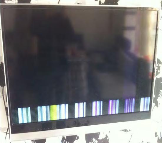
9 LCD & LED TV Repair Tips Page 9 Note: Most of these repair tips are not included the fault of electrolytic capacitors! Because of the electrolytic capacitor bulge or bad on ESR values are easily detected by the ESR Capacitor Tester. Before read these repair tips, please make sure that you had testing the electrolytic capacitors first. 1) Model: ChangHong LED32B1000C LED TV Symptom: No Power, Dead The Power Supply board is using HSS35D-1MF Repair/Solution: Open the TV rear cover, look at the PSU board and can t find any burn component on it. Checking the F101 main fuse is ok. Power on the TV, their 5V, 12V & 24V all no outputs. Suspect the PFC section failure. Measure the big filter cap is only 302V, instead of 380V! That s mean their PFC section not working. So power off TV and using the Multimeter testing the PFC circuit components and found that Q108, Q109 and Q110 (all are 2T (4403) marking code, SMD) all are gone. So using the 2A (3906) SMD as a replacement and the TV is working properly. Actually this is a common fault in this PSU HSS35D- 1MF board. 2) Model: ChangHong LED43A9000i LED TV Symptom: Display Problem Randomly- Distortion or No Display

10 Page 10

11 Page 11 Repair/Solution: Customer complaints this TV after use about several hours the TV display will distortion or no display. Normally this type of problem is difficult to diagnose. This LED TV using Samsung LTA43HN01 LED Panel, T-CON board is K160HZC2LV0.1. From the above fault picture, suspect the LVDS cable, T-con board, FPC cable/s or the LED Panel. Remove the LVDS cable and FPC cables, using the eraser to clean their contact pins (Golden Fingers). After clean the LVDS cable connector, also checking their LVDS socket contact points on the T-con board. After finish cleaning, power on the TV to testing it and found that the TV was back to normal and problem solved! Even burn test the TV whole day also no problem.

12 Page 12 3) Model: LG 60LS5700-UA & 60LS5750-UA LCD TV Symptom: No Display but Sound is Normal The TV front buttons are all working well. Repair/Solution: The Power Supply voltage outputs are all normal. This TV backlight is lit and the sound is OK. The T-con board Vcc voltage 12V was present. That s mean their backlight system, PSU board and Main board are all OK. So suspect the T-con board failure. Power off the TV, measure the T-con board SMD fuse (5A, 32V) was opened. Before replace the fuse, check the Vcc line and found that their ohm value is very low (below 100 ohm). After trace the Vcc line to IC301 (17140E) and confirm that this IC was shorted. Because of this IC no stock, so direct replace this T-con board (p/n: AGF ) and the problem solved.


13 Page 13 For your information, the new T-con board will use the 17140AE (IC301), the older version is using the 17140E.

14 Page 14 4) Model: LG 32LX3DC-UA, 32LXDCS-UA LCD TV Symptom: Remote Control Operation Error in Stand-by Mode When Power Remote button is operated in stand-by mode, set will not respond or intermittent not working. Repair/Solution: This TV has using the IR Assembly unit with design bug. So the IR Assembly unit with these part numbers will cause this issue too. The part numbers are: A, 3911TR0006A & 3911TR0004A. Their replacement IR Assembly unit is using this part number: 39119S0082A. If not change the IR Assembly unit, just add a 100 ohm resistor into it and the problem solved. Refer to the picture below:

15 Page 15 5) Model: LG 26LD350 and 32LD350-UB LCD TV Symptom: TV No Start-up When TV is turned on, Power LED light is blue, but set has no sound and no display. Repair/Solution: This is because the IC405 not working properly. Power enable has incorrect voltage supplied. Replace the Main board or the improvement method to solve this problem. Replace Main board with corrected change in resistance in Power On/Off1 to IC405. Add: R403 (33K, 1/16w), R404 (33K, 1/16w), R407 (10K, 1/16w) and R408 (10K, 1/16w) Delete: R456 (10K, 1/16w) & R459 (10K, 1/16w)

16 Page 16
17 Page 17 6) Model: Philips 26PFL3403D-10 Chassis TCM2.0E LA LCD TV Symptom: No Power/ Dead Repair/Solution: This PSU board standby 5V, 12V and 24V all no outputs. Checking the PFC section filter capacitor C5 (150uF/450V) has 302V only. Check the standby circuit and found that RB5 was opened. It is a SMD fuse and marking code is C, that s mean it is a 0.2A or 200mA fuse. After replace it, the TV can startup and operate properly. 7) Model: Samsung 2012 Series TV Symptom: How to Troubleshoot the TV Bluetooth Module Repair/Solution: You can troubleshoot the Bluetooth Module by measuring the voltages at the connector pins on the Module.


18 Page With the TV in Standby mode, measure pins 2, 3, 8 and verify that the DC voltages are correct. If the voltages are missing or not correct, check the cabling and voltage supply feed from the Main board. 2. Turn on the TV, measure pins 2, 3, 8 and also pin 1for correct DC supply voltages. If the voltages are missing or not correct, check the cable and supply feed the Main board. 3. Now measure pins 4 and 5 which are the Bluetooth signals. If the voltages for pins 4 and 5 are missing or not correct in the Power On state, the problem is likely the Bluetooth module. Note: For other brands and model TV with Bluetooth Module, their troubleshoot method is nearly same like this repair tips. So you can using this tip as a reference.
.")

19 Page 19 8) Model: Samsung ES7500 and ES8000 Series 2012 LED TV Symptom: Auto Power Cycling/Reset Issue The TV sometimes displays vertical lines on the screen and then turns OFF and ON by itself. The WD Count in Service Menu> Control>Sub Option is higher than 0. Repair/Solution: 1. Check the power cable between the Main board and PSU (Power Supply). If the cable or connector on the PSU is discolored, replace the cable. After that using the PSU self test methods to make sure that is working properly or not, if not then replace it. If the cable or connector on the Main board is discolored, replace the cable and Main board. If the cables and connectors are all OK, do not replace the cable or PSU or Main board and skip it to Step 2 below. 2. Check or replace both LVDS cable and their T-con board.


20 Page 20 9) Model: Samsung UN46C8000 LED TV Symptom: Half the Screen has a Red Solarisation Effect Picture 1 Picture 2

21 Page 21 Repair/Solution: Picture 1 shows the problem: Red solarisation on the bottom of the screen. Your first impulse is probably to replace the panel, but if you look closely, you ll notice that solarisation appears only on the right side of the screen. The left side does not show the problem. This tells you it s not a panel issue. What should you consider? The signal source PCB, or LVDS cable connections. To see if it s a signal source issue, enter the service mode and check the test patterns. This is shown in Picture 2. Notice that in service mode, the right side is all Red, showing you that the signal source is not the problem. This leaves three items as the probable cause: the Main board, the LVDS, the T-con board or the FPC cable. In this case, the cause was the LVDS cable connector on Main board. It was not closing tightly enough. Putting hand pressure on the connector there caused the problem to come and go. So try to using the strong tape or silicon glue to fix the connector and prevent it loose again. So the TV problem was solved. 10) Model: Samsung UN46D6500VFXZA LED TV Symptom: Ghosting Image or Double Image Vertically.


22 Page 22 Repair/Solution: Checking or replace the T-con. Before that, make sure to clean the LVDS and FPC cable contact pins with eraser. 11) Model: Samsung LN55C650 LCD TV Symptom: The Screen has Colored Vertical Lines

23 Page 23 Repair/Solution: If the lines appear in the Picture Test/OSD Menu, the cause is a bad panel. If the lines do not appear, disconnect all signal sources and check again. If the lines are still in the Picture Test, checking the LVDS cable contacts or change the Main board. If the lines are gone, then a signal source is causing the problem. 12) Model: Samsung UN46C6500 LED TV Symptom: A Thin Vertical Line and Bar in the Test/OSD Menu. Repair/Solution: If the lines appear in the Picture Test, the cause is a bad panel. If the lines do not appear, disconnect all signal sources and check again. If the lines are still in the Picture Test, checking the LVDS cable contacts or change the Main board. If the lines are gone, then a signal source is causing the problem.

24 Page 24 13) Model: Samsung LN32D450G1D LCD TV Symptom: The Screen has Double Vertical Lines Repair/Solution: If the lines appear in the OSD Menu, the cause is a bad panel. If the lines do not appear, disconnect all signal sources and check again. If the lines are still over the OSD Menu, so checking the LVDS cable contacts or change the Main board. If the lines are gone with different video signal input, then a signal source is causing the problem, so you need to trace that video input circuit to find out what s wrong in it. But most of the time, this type of symptom were causing by the LCD Panel, bad COF contact in between Source Driver board or the other side of the Panel glass contact pins.


25 Page 25 14) Model: Samsung LN37A550P1F LCD TV Symptom: The Screen One Side is Darker than the other. Repair/Solution: Try to call out the OSD Menu. If one side is darker than the other, it s a bad T- con board or FPC cable. If the OSD Menu is fine, then checking the LVDS cable and main board. Most of the time is their FPC cable contact pins dirty. After clean the screen problem solved.

26 Page 26 15) Model: Samsung UN60D7000 LED TV Symptom: These s a Thin Vertical Line on the Left Side of the Menu Repair/Solution: Try to call out the OSD Menu or Smart Hub Page. If the line goes through the OSD Menu or Smart Hub like the picture above, the panel is bad. If it s behind the OSD Menu, disconnect all signal sources and check again. If the vertical line is still behind the OSD Menu, then checking the LVDS cable or replace the main board. If the line is gone, then the signal source is the problem. Or try to use the finger to touch or knock the top cover of that line position. If the line can missing randomly, that s mean their COF or TAB contacts was dry join on the Panel.

27 Page 27 16) Model: Samsung LED TV Symptom: The Picture is Upside Down When you ordered the Main board for an LED TV, after installing, you notice that the picture is upside down! Repair/Solution: First, make sure the OPTION BYTE settings are correct. If setting the Option Byte settings does not correct the problem, enter the service mode and adjust the HV FLIP settings (Toggle the setting on or off). Entering Factory Mode: To enter Service Mode, press the remote control keys in this sequence: MUTE Power On. Then, select Control -> Config Option -> HV FLIKP. See the illustrations below:

28 Page 28 After you have changed the HV FLIP setting, power cycle the TV (turn it off and then on) to lock in the setting. Note: Whenever you replace a main board or lcd panel, always refer to the OPTION BYTE list to verify that the settings are correct. Option Bytes mainly match the correct drive to the panel, but can also have effects based on feature functionality. Some of the settings, if not set correctly, may cause minor defects in the overall operation of a TV. These defects are often not immediately obvious and may be discovered by the customer days after the repair. 17) Model: Sharp LCD-32D500A-BK LCD TV Symptom: Backlight ON & OFF, then No Display When power on the TV, everything is OK, after about 2 seconds, display darkness and then no display. After 2 seconds, display back to normal, but after about 2 seconds it will no display. This will happen several times, after that the TV will auto shutdown. Sound is normal. Inverter Board Part Code: RUNTKA673WJQZ Repair/Solution: Suspect their CCFL lamp defective. Use the CCFL tester to testing the lamps, all looking good. Measure the PWR_ON/OFF, BL_ON and DIM signals all


29 Page 29 normal and stable. The inverter board 24V input voltage also OK. So the problem looks like is the inverter board. Checking the inverter board MOSFET, HV Transformer and caps all are OK. So replace the inverter IC BD9893F and the problem solved. 18) Model: Sony KLV-32BX205 LCD TV Symptom: When Power On the TV, the Screen show Binary File Detecting, After that TV Shutdown. Repair/Solution: Try to re-program their flash memory but no help. The TV owner said this TV has water by his children. When checking their front button, it has liquid inside the buttons. Use the alcohol to cleaning these buttons. Power on the TV and it is working properly.

30 Page 30 19) Model: TCL L32E09 LCD TV Symptom: Stuck in Standby Mode Repair/Solution: This LCD TV look like dead, but when checking their Backlight and PSU voltages all working properly. But the Main board PS_ON signal is missing. When testing the Main board all LDO DC-DC circuit, 5V, 3,3V, 2.5V and 1.27V are normal and stable. Try to using the Remote Control or front button also not working at all. Measure the flash memory IC U104 (S25FL040A) Vcc voltage input is OK, their Main Chipset can feel some warm temperature. So suspect the TV is their firmware corrupted. Use the ISP Programmer, first checking their Initial Serial Print Info and found that all information is garbled. Try to re-programmer their firmware, but also no help. So the last suspect is maybe their Main Chipset (U112, BGA type) or the crystal X100 ( MHz). Replace the crystal X100, the problem solved! Try to using the ISP Programmer to checking their Initial Serial Print Info, all are ok now.
31 Page 31 20) Model: TCL L46E5300A 3D LED TV Symptom: TV No Sound after 1~2 Hours Repair/Solution: When testing this TV, after about 1 hours, the sound will randomly on and off, after that totally no sound. So try to using other signal input like AV and HDMI also same symptom. Because of this TV after warm up the problem will occur, and then suspect that Main board Audio section has component sensitive with heat increase. Try to using the Hair Dryer to shoot to the Main board Audio section and found that just using about 10 minutes, the TV no sound symptom occur. So confirm that the Audio section is the causing this symptom. When testing the U701 (TAS5707) each pins, found that pin 19 (control MUTE function pin), when TV has normal sound it is about 3.3V. After the hair dryer shooting to Audio section, it is slowly drop to 0V and the sound gone! So suspect their MUTE circuit has component fail/sensitive after heat increases. Use hair dryer to concentrate shooting on this circuit and found one SMD capacitor C735 (1uF) leakage and sensitive in heat increase. After replace this cap, the TV no sound problem solved!
32 Page 32 21) Model: Xoceco_Prima LC-52HW35 LCD TV Symptom: TV Channel No Display, but Other Signal Input Normal Repair/Solution: Check the PSU board output voltages normal, Main Board LDO (DC-DC) output voltages normal and stable. Checking the TV Tuner all voltages OK, but found that their clock signal lines SCL and SDA was drop to 0.8V, normally it is about 5V. These two lines are go to the Tuner section, so disconnect these two lines, the SDA & SCL lines are back to about 5V! So trace these two lines to the Tuner section and found that Tuner socket got two pins was shorted. After re-solder these two pins, this TV problem solved!
33 How to Isolate the LCD TV Problem Fast Page 33 I ve receive lots of the to ask me how to repair the TV no display problem or etc? But they are never provided more details or information about the TV. For example the TV brand, model number (for Philips TV must provide with their Chassis Number), TV symptoms, what s their power supply secondary voltage output values and so on. Because of this reason, this chapter will help the repairer learn more about how to isolate the LCD/LED TV problem before starting repair it. When you know how to isolate the TV problem fast, then you can quickly repair the LCD/LED TV in board levels repair. So that you need to know about these: A) Basic Knowledge B) How LCD TV Work C) The Method and Tools to Help Isolate the LCD TV Problem A) Basic Knowledge Before starting to check the TV, the very first step is listening to the customer. The TV problem complaint by the owner/customer After that, power on the TV to look at their symptom is it same describe as the customer complaint. Remember, if the TV complaint shorted and will causing the home main Power System shutdown (PLCB fuse/switch activate), this TV can t power on first, but need to open their rear cover to checking their Power Supply board first. If the TV problem same as the customer describe, so we can start to check the TV now. If the TV symptom is different than what customer describe, then we need to call the customer first before proceed it. Lots of the LCD & LED TV they have self test system. When an abnormally occurs in TV, the self test protection circuit will operate and reset the unit to standby mode. During this time, the defective block/board can be identified by the number of blinking times of the Power LED on the front panel of the TV. If the self test system found that the CCFL lamps abnormal or disconnected, it will shutdown the backlight system and then provide the error message or error code to let the repair engineer easy to know what s wrong inside the TV. So their TV

34 Page 34 front Power LED light will blink differently, for example: LED light blinking 1 times then stop 2 seconds and continue to blinking 1 times. To find out what s meaning of these LED light blinking, you need to refer to their service manual. But not all the service manual will show their error chart. So you need to search other nearest model service manual to compare with it. Panasonic TC-L32C22 Power LED Blinking Timing Chart Sony KLV-32S310 LCD TV Standby LED Timing Chart
35 Page 35 If the TV malfunction and show the error code (blinking times), you roughly know where to check and repair it. If you re doing the board level repair, then you can direct replace the PCB board to solve the TV problem. Or you need to do the components level repair, then you need to concentrate to checking the appropriate PCB board, when found the defective component/s, then you can direct replace the components and solve the TV problem with the lowest cost compare with board level repair. If the Power LED light blinking non-stop or with the relay tic..tac.. sound inside the TV, that s mean something wrong in the PSU board or their loading shorted. So you need to check their PSU board first. B) How LCD TV Works Here is the basic information of how LCD TV works. Actually this information/knowledge you must know before you starting to repair the TV. If not, you will not sure where to troubleshoot the TV first. The whole set of LCD TV is just have 7 parts/pcb in it. They are: 1) Power Supply Board 2) Inverter Board 3) CCFL/EEFL lamps 4) Main Board 5) Front Panel PCB 6) T-CON board 7) LCD Panel Some LCD TV, their use the IP board (Power Supply + Inverter in one board) and the T-CON board was built-in the LCD Panel. So some LCD TV just has 5 parts/pcbs only.

36 Page 36 1) IP Board (Inverter Power Supply Board) * The IP Board or Power Supply board feature is use to input the AC voltage supply and converter it into DC voltage supply. The IP Board is Power Supply + Inverter section built-in it. For the Power Supply Board, it is only use to generate the DC voltage supply only. The Power Supply board will generate several output DC voltage supply in their secondary side and supply it to Main board, Inverter board/section and T-CON board (but this voltage supply will go through and control by Main board). * The Inverter Board/Section is use to step up the low voltage (DC voltage) to output high voltage (VAC) to start-up the CCFL/EEFL lamps. Normally the voltage input to inverter board is 24Vdc and their voltage output is about 1500Vac (start-up) and then will steady at 600~800Vac (it will depends on what types of lamps in use). * Normally the Power Supply or IP board will generate 5VSTB (standby voltage), 24V, 12V, 5V, 3.3V and 18V (or other voltage values for Audio section use).
37 Page 37 2) Front Panel PCB (Key Board) * This PCB board feature is to input the command from front buttons and remote control and then send to Main Board. Some LCD & LED TV design is built-in this PCB into the Power Supply Board. 3) Main board * The Main board has lots of the features inside. It s function like the computer main board. But it can divide to 4 parts: i) With the Main board CPU + MCU (microcontroller unit), its can control the whole system through send out the signals. For example the signals like PS_ON, BL_ON, PANEL_ON and etc. ii) Process different types of video signal inputs. For example: TV Tuner, AV, HDMI, PC, S-Video, USB & etc. After that the Main board will convert these video signal inputs to RSDS type video signals and send to T-Con Board through LVDS cable. At the same time, the Main board will also process the audio signals and amplify it and send to the speaker. iii) The Main board DC-DC section. This is a very important section in Main board. This section will received the voltage supply from the Power Supply board and generate the appropriate DC voltage to other system use. For example, CPU core power, CPU Vcc, DDR RAM Vcc, Tuner Vcc and all analogue and digital circuits use. iv) If that is SMART TV with 3D, WIFI & etc features, so these TV Main board will have add in or built-in 3D or WIFI features card/plug-in into the Main board. 4) T-CON Board * The T-CON board is use to receive the LVDS format video signals and convert it into TTL (Transistor Transistor Logic) or RSDS (Reduced Swing Differential Signaling) signals. These signals can driving the LCD Panel to working and generate the complete display in the screen. * Not only that, the T-con board has another important section, which is a DC-DC circuit. This DC-DC section received the voltage supply (Vcc) from the Power Supply and through the Main board. After that, convert it into several voltages and supply to the T-con board and also to driving the LCD Panel too.
38 Page 38 5) LCD Panel * The feature of LCD Panel is to convert the video signals into a complete display or picture in the screen. 6) The CCFL/EEFL lamps were inside the LCD Panel * If the LCD Panel without the backlight, the screen will darkness and hard to see their contents or display. The Backlight system is using the CCFL/EEFL lamps (with the voltage supply from Inverter board) or LED strip (with the voltage supply from LED Driver board) to generate the back light. A Simple Description of How LCD TV Work When the TV power cord connects to AC supply and switch it ON, the LCD TV PSU board will automatic received this AC voltage input. After that the PSU board will automatically generate the Standby Voltage 5V (5VSTB) and send to Main board. They are not any other voltages in PSU board except the 5VSTB. When the Main Board received the 5V standby voltage from PSU board, it will going through a voltage regulator IC or DC-DC circuit to generate the 3.3V voltage. After that, this 3.3V will supply to MCU (microcontroller unit) IC, CPU and the Front Panel board. So that we can see the standby LED light is lit in front of the TV. The TV is in the Standby Mode now. After press the power on switch button in Front Panel board or remote control, the Main board will send out the Power On signal (PS_ON, PWR_ON or etc marking code) to PSU board. This PS_ON signal will send to Power Supply board PFC section and then the PWM section to generate other voltage outputs like 24V, 12V, 5V, 3.3V and etc to Main board, T-con board and Inverter board/section. Finally the TV can show the display now.
39 Page 39 C) The Method and Tools to Help Isolate the LCD TV Problem In this stage, we must have some electronic testing skills to troubleshoot the TV. If you think your skill is not enough to do that, then I will highly recommend you read these e-books: Testing Electronic Components & SMPS Power Supply Repair Guide at: Here is the list of TV problems is always occurring in LCD TV: 1) No Power/Dead (no any LED light lit in front the of Front Panel board) * If the TV is No Power symptom, first need to check their Power Supply AC input after fuse is appear or not. If it is appear 110Vac or 220 Vac, that s mean the AC input, power switch and fuse is ok. If not you need to check the AC plug main switch is press ON or not. Check the power cord and the fuse also. If the 110Vac or 220Vac appear, but PSU secondary side no voltage outputs then you need to replace a working PSU board to solve this problem. If their Standby voltage 5V is appear but other voltages are no output then you need to check the Main board and the Front Panel board. If you have learned the V3.0 ebook, then you can use the PSU self test method to confirm it is the Main board or backlight problem. 2) No Display & No Sound (but the LED light is lit or LED light blinking) * When the TV No Display but the LED light is lit from Red change to Blue or Green color light, that s mean the Main board has sent out the start-up signal to PSU board. But the actual situation is we need to know the PSU board has output all the voltages correctly. So that still need to checking the PSU board secondary side output voltages is normal and stable or not. If all voltages output normal and stable (including the BL_ON and PS_ON signals appears), that s mean the problem is in the Main board. Make sure that s in the TV Mode, if not sure then you must also check their T-con board too. * When the TV No Display but their LED light is blinking nonstop, so need to check their standby 5VSTB is normal or not. If the 5VSTB is normal
40 Page 40 and stable, also need to know the PS_ON signal appears or not. If the PS_ON signal not appears, need to check the Main board and their Front Panel PCB board. In this case, disconnect the Front Panel PCB from the Main board and power on the TV again, if the TV can show the display normally, that s mean the Front Panel PCB is something wrong happen in it. If after replace the Front Panel PCB still same symptom, then need to check the Main board or replace it. * When the TV No Display & No Sound but the LED light is blinking few times then stop and continue to blinks, this type of LED blinking is showing the error code to the repairer. Regarding this type of symptom, you need to refer to their service manual to find out what s the meaning of this error code like I wrote in this chapter (A) Basic Knowledge there. 3) No Display but Sound Normal * If the TV is No Display but sound normal, sometime we can hear the sound from TV channel changed. For this symptom, need to know: a) If their backlight is lit, need to check the T-con board Vcc voltage input after SMD fuse. If the Vcc voltage appear (typically it is 12V or 5V), the higher opportunity is the T-con board gone. So replace a working T-con board to give it a try. b) If this TV backlight is off, need to check the BL_ON & PDIM signals are appear or not. If not appear, the problem is in the Main board there. If these signals appear, the problem is in the inverter board/section or their CCFL/EEFL lamps. 4) No Display in Certain Video Signal Input * If the TV can show the display in one of the video signal input, but other video signal inputs are ok, so this type of TV symptom is causing by the Main board. If want to do the components level repair, need to check their appropriate section. For example the HDMI section, AV section and etc. 5) No Display after Several Seconds (or call it as Backlight shutdown) * This type of TV symptom is causing by their inverter board/section or the CCFL lamp/s. Before that, make sure their BL_ON and PDIM signals are normal and stable. If not stable or abnormal, need to check and tracing it to the Main board there. If not sure problem is causing by Inverter board or CCFL lamp/s, we can use the CCFL lamp Tester to testing it. So that we can confirm it
41 Page 41 is the inverter problem and their CCFL lamps are ok. With this tool, we can quickly found that s the inverter or their CCFL lamps problem. 6) Display Problem/Abnormal Display * This type of symptom we can divide it into: a) Black Screen/No Display: For this symptom, please refer to the 2), 3) & 4) in this chapter. b) Grey Screen Problem: This type of problem is same as the 3) a. c) Vertical Lines/Bars in the Screen: If the lines/bars is across the OSD Menu and all the video signal inputs also same result, that s mean this TV LCD Panel is defective. d) Horizontal Lines/Bar in the Screen: If the lines/bars is across the OSD Menu and all the video signal inputs also same result, that s mean this TV LCD Panel is defective. e) Half Screen Blank but Another Half is Normal: Mostly this type of symptom is causing by their FPC cable/s. This cable is output from the T-CON to Source Driver board. Besides the FPC cable, their connectors in T-CON board and the Source Driver Board must check also. Because some repairer after they replace the T-con board and solved this type of problem, but their actual problem was because of the connector dry joins or etc problem only. Or the Half Screen is Abnormal but another Half Screen is normal then this type of problem is causing by their T-CON board. f) Negative Picture: This type of problem was because of their T-con board GAMMA circuit malfunction. So just replace the T-con board and the problem solved.
42 Page 42 g) Display Distortion: For this type of TV symptom, it is hard to say which section is defective, but most of the time, it is causing by the T-con board or Main board. h) Display Full of Vertical Color Lines: This type of TV problem, we must call out the OSD Menu to confirm. If the OSD Menu is showing normally in the screen but their background is fully of vertical lines then this symptom is causing by the Main board or their LVDS cable. i) Display is Opposite in the Screen: This type of symptom is causing by their Main board firmware setting or firmware corrupted. The above information is just for the repairers who want to repair the TV in board levels repair only. If you need to do the components levels repair, you need to learn more in this ebook and my other series ebook like V1.01, V2.0, V3.0 or etc.
43 Another Main Board Secret Repair Tips Page 43 Nowadays, lots of LCD or LED TV Main board problem difficult to repair it. Even you had checking all the components in the Main board or re-program their flash memory IC or EEPROM but no help too. So what s happen to the TV Main board? Why can t to repair it? But after buy a new Main board to replace it, the problem solved! Finally, found the answer for this Main board problem. Actually it is causing by their Main board LDO and DC-DC circuits!!! Some repairer may said, I had checking their voltage outputs properly and values are stable too. Yes, even their output voltage value is correct and stable, BUT some of these output voltage values are not accept by the Main board Chips like their CPU, DDR RAM & the Flash memory! So, is it hard to repair and expensive to replace it? NO, it is cheap and easy to get it! Note: LDO is stand for Low-DropOut Regulator (
 TV stuck in standby mode because of the POWER_ON signal missing.")
44 Page 44 The above two sample of DC-DC & LDO Voltage Output Circuits Note: The LDO circuit normally using the IC like: 1117 series, 1084 series & etc. For the DC-DC circuit, it is using the IC like: AOZ1041, AOZ1072, AP1534, MP1482, MP2212 & etc. The Main board problem like: 1) TV stuck in standby mode because of the POWER_ON signal missing. 2) The TV Backlight problem and causing by their BL_ON signal missing. 3) TV some time can start-up but some time not. The POWER_ON signal unstable and causing the TV non-stop on and off. 4) The TV Backlight flickering and causing by the BL_ON signal unstable. 5) Display Distortion 6) No Display, even the power LED light change from Red to Blue color light. 7) And other strange TV problem.. From the above TV symptoms, even you had confirm their Power Supply (PSU) board is ok, inverter board/section is ok, CCFL lamps or LED strip are ok, T- con board is ok and even the LCD/LED panel is ok too.
45 Page 45 When you confirm that the problem was the Main board, some of the repairer will stop checking it, or just measure some common components then replace the whole Main board and the problem solved and case closed. For some repairer, they will continue to checking the Main board with these steps: 1) Checking the Main board output signals like POWER_ON and BL_ON are normal and stable or not. 2) Checking Main board LDO & DC-DC circuit voltage outputs values is normal and stable or not. 3) If all voltage outputs are normal and stable, they will continue to checking the Flash Memory and the EEPROM circuits. 4) After that checking the CPU (Main Chip) Vcc input voltages, crystal and reset circuit. Or try to replace the crystal and give it a try. 5) Also checking the DDR Ram Vcc and their other signals lines too. 6) If above steps all also no help, then it can try to re-program the correct firmware to Flash Memory using ISP Programmer. Also try to replace an empty EEPROM IC into the Main board and give it a try (most main board can accept this method, but little Main board will not). Or replace the Flash memory or EEPROM IC to give it a try. 7) If still no help, then replace the CPU (Main Chip). But most of the repairer after doing step No.6 they will give up and replace the whole Main board. Actually the TV Main board CPU Core Power (normally are 1.26V, 1.2V or 0.9V, it will depends on their design) voltage require very strict to it. For example the 1.26V core voltage line, If a bit different voltage values, when testing it with 1.29V or 1.3V values, then this voltage is not accept by the CPU and will causing the Main board not working or working abnormal. So the acceptable voltage values for 1.26V core power will be 1.25V~1.27V. The LG 42LK530 LCD TV Main board it is using 0.9V of their CPU core power. So what will cause the CPU not working or working abnormal except the voltage input not correct or not stable? Yes, the answer is the Ripple Voltage for this CPU core power!

46 Page 46 This is a sample voltage output of CPU core power 1.26V Not only the CPU, the DDR RAM also require the voltage input very strict and stable! The Flash Memory voltage input also same too. So lots of the TV repairer they don t know about this, or even know about this, but the Oscilloscope also can t detect this Ripple voltage in the LDO or DC-DC output! If this Ripple Voltage over 10mV (some Main board will accept to not more than 100mV ripple voltage, depends on the Main board design), the CPU will not working or working abnormally. If the Ripple Voltage is below 10mV, it is acceptable by the CPU core power system. So the TV repairer will think this output voltage is ok and can be trusted (Because of the Multimeter and Oscilloscope not detect any abnormal values or waveform there). But from lots of the Main board repair case, this Ripple Voltage always occurs in CPU core power input and the DDR Ram Vcc input! This causing lots of the strange problem in Main board and can t be repair (the repairer don t know about this) also throw this Main board in the trash can. After you learn this tip, if you had throw this type of Main board in the trash can before, you will regret it.
47 Page 47 The method to solve this Ripple Voltage in LDO or DC-DC circuit is JUST add an Electrolytic Capacitor parallel with the voltage output line, if the problem gone, that s mean their LDO or DC-DC output circuit has/have filter capacitor/s out of values, bad ESR or etc problem. So just replace the old electrolytic capacitor in the circuit with a new one. The values of that capacitor should be same or a bit more capacitance than the old one. For example, if the original capacitance values are 100uF/16V, you can replace it with 100uF or 220uF/16V (use a good quality electrolytic capacitor and its better using 105 C type). For the CPU core power DC-DC circuit, normally it will use the 220uF~470uF/16V, the DDR Ram LDO circuit will use about 47uF~100uF/16V. The DDR Ram (Vcc input and DDR Vref lines) LDO or DC-DC circuit, their output voltage line better put the 100~220uF/16V electrolytic capacitor for more stable.

48 Page 48 Main Board Repair Tips 1) Model: Skyworth 42L05HF LCD TV Chassis: 8M60 Main board chassis Symptom: TV Can t Start-up, Power LED Light Change from Red to Blue Color. After open the rear cover, their backlight can lit about 10 seconds, then shutdown about 5 seconds. After that the backlight will lit about 10 seconds and it will on & off repeatedly. But the TV screen is always no display. Skyworth 42L05HF Chassis 8M60 Main board
49 Page 49 Repair/Solution: Open the TV rear cover, testing their PSU voltage outputs. The 24V= 23.8V, 12V= 12.5V and 5VSTB= 5.04V all are ok and stable. Checking the PR ON/OFF signal has 2.65V but the BL-ON/OFF signal not stable. This BL- ON/OFF signal voltage repeated changed from 4.93V~0.02V. When the backlight lit about 10 seconds, this BL-ON/OFF signal has 4.93V, when backlight off about 5 seconds, the signal voltage has 0.02V only. So suspect the CCFL lamp/s or the inverter board failure. Use the PSU self test method (I had mention it in my V3.0 ebook before), to testing the PSU and the backlight system. Surprisingly, PSU board and the backlight system are working properly! The BL-ON/OFF line disconnect to inverter board and testing it in the Main board there. Found this BL-ON/OFF signal voltage still up and down. So confirm that the problem was in TV Main board. The steps to checking the TV Main board are: 1) LDO and DC-DC circuits 2) EEPROM and Flash Memory circuit 3) CPU Reset circuit 4) CPU Crystal 5) DDR Ram circuit 6) Try to replace the firmware for Flash Memory with ISP Programmer 7) Replace DDR Ram or CPU chip or just replace a new Main board. To checking the LDO & DC-DC circuits in TV Main board, we need to use the Main board schematic diagram to know how many LDO or DC-DC circuits in this board. Below is the voltage output value of this Main board: 1) U2 (LDO) 3.3VSTB= 3.331V 2) U3 (LDO) DDR_1.8= 1.818V 3) U4 (LDO) ADC_33= 3.351V
50 Page 50 4) U12 (LDO) 5V_IF= 5.02V 5) U21 (DC-DC) 5V= 5.03V 6) U25 (DC-DC) VDDC= 1.273V (CPU core power 1.26V) 7) U26 (DC-DC) 5V_USB= 5.02V The above voltage values look like normal and stable. So the next step will be checking the EEPROM and Flash Memory. So measure the EEPROM Vcc input, SCL & SDA signals, all are good and stable. The Flash Memory Vcc input and the CLK signal also OK. So continue to checking the CPU reset circuit and the crystal waveform. The Reset Circuit is operating properly. When checking the Crystal, the oscilloscope can detect the Sine waveform, but sometime this waveform will missing and come again! So suspect this Y1 crystal (12MHz) is failure and tries to replace it with a new one. But TV problem still the same and no change!
 divided by two. Also check their control signals and the clock signals in between to CPU there.")
51 Page 51 The Main board CPU Reset Circuit and the Crystal To checking the DDR Ram, normally just to measure their Vdd voltage input and the Vref (Reference Voltage) voltage. This Vref voltage is about 0.9V, it is using the input voltage Vdd (1.8V) divided by two. Also check their control signals and the clock signals in between to CPU there. These Control signals are: RAS, CAS, WE and CS. The Clock signal like: CK & CKE. Make sure these signals are reach to the CPU there. Sometime these signals will break in half way. This is because of the PCB circuit hole causing the signal line broken and these signals can t communicate with the CPU. After checking all these signals and the voltage inputs, all are normal.

52 Page 52 This Main board using Qimonda HYB18TC1G160C2F-2.5 DDR RAM Since the above steps can t find out what s wrong in this Main board, so just try to using the ISP Programmer to re-program their Flash Memory firmware. Remember, the firmware MUST find out the correct version and suitable for the LCD Panel. One more thing, before re-program the Flash Memory, I highly recommend to backup their old firmware first before replace it with the new one. Finally found the correct version and same LCD Panel firmware to this Main board. The result is still same problem! The last remaining is replacing the DDR Ram, CPU or just replaces a new Main board. Suddenly think of the supply voltage to CPU core power and the DDR Ram if their Ripple Voltage higher than 10mV will cause the Main board not working or working abnormal. So use a 470uF/16V electrolytic capacitor connect parallel with their CPU core power DC-DC voltage output (U25) there, but the problem still persist. And then use a 220uF/16V capacitor connect it with their U3 LDO voltage output to

53 Page 53 DDR Ram, suddenly the problem gone and the TV can show the display perfectly! Wow, just a cap can solved this TV problem. Uses the capacitance meter to testing CA103 and CA105 both capacitance and ESR values are normal. The other ceramic capacitors all looks like good. So decide to replace the CA105 with a 220uF/16V electrolytic capacitor into it. Finally this TV problem solved! Conclusion: Starting now, when repair the TV Main board with strange problem, first step try to checking their LDO and DC-DC voltage outputs. If all voltage outputs normal and stable, then directly add the electrolytic capacitor into the voltage input of CPU core power, DDR Ram and the Flash Memory. It will save your time and the money too!
54 Page 54 2) Model: Sanyo LCD-32CA828 LCD TV Symptom: TV Auto Shutdown Randomly This TV will auto shutdown randomly, but sometime it can work whole day without any problem. When the TV auto shutdown, after a while it will auto power on the TV and till the display show SANYO logo then auto shutdown again! When the problems occur, it will non-stop to shutdown and then auto power on again. But some time it can work properly! Repair/Solution: Even try the repair tip procedure on (1) above, still can t find any problem. After that, think about the Main board LDO and DC-DC circuit Ripple Voltage issue. So try to add the electrolytic capacitor 220uF/16V to DDR Vcc input line and their DDR Vref (Reference Voltage) line. But the problems still same. After that, add another 220uF/16V capacitor to CPU core power line, parallel with C747, power on the TV and the problem solved!! Replace the C747 capacitor with a 470uF/16V cap. This TV even burn test several days, but it still can working in good condition. Finally this TV problem was solved. This Main Board Secret Repair Tips Can Apply to: 1) LCD, LED & Plasma TV Main board 2) LCD & LED Monitor Main board 3) Laptop & Desktop Main board 4) CNC machine Main board 5) Or all the Main board using the big Chipset with CPU inside & has their core power in it, so you can try this tip to it. Also the Main board has high speed DDR/SD Ram circuits; you can try to use this method too. I m happy to receive your about how you successful to repair the Main board with this tip and also what s type of Main board it is.
55 Page 55 NOTE: For the SHARP LCD/LED TV, some of their TV Main board has a special function, when the problem occurs about 5 times (on the TV, but it s not working, after that off and power on again the TV, it will count as two times already), their TV Main board will store the error code inside Main board memory IC. So even you re solved the problem like changed the PSU board, inverter or lamps, the TV is still not working. The front LED light will flashing Red, Green then Red again and non-stop or etc. Unless you change the Main board, the TV will work! Actually this problem is easy to solve, if you know how to do that. If you don t know, then you will need to replace the Main board. So the solution is just login to the Service Mode to clear their Failure Mode Memory and then save & exit the Service Mode and the TV problem solved. For more details on how to do that, you can refer to my LCD TV Repair Tips V2.0 ebook, pages 53. So this is an exception case of the Main board problem. Their Main board is ok, just you need to know what s happen into it, and then you can fix it.

56 How to find a Substitution of SPI Serial Flash Memory and EEPROM ICs in LCD/LED TV and Monitor Page 56 Nowadays, lots of the LCD/LED TV and Monitor use the memory IC to store the data and firmware on their Main board. Besides to using the Programmer to send data or firmware to memory IC, as a TV repairer, most of the times they want to replace the EEPROM IC or Flash Memory to make sure that memory IC is normal or not. Because of the EEPROM and Flash Memory IC have lots of brands and part numbers, so the repairer cannot prepare all type of memory IC. Actually all electronic component inside the PCB board, it is better to use the original part number to replace it. But some time it is difficult to do that, especially you don t have the same part number to replace it. So this information is to let you know, how to choose the right memory IC for the Main board. How to Choose a Substitute EEPROM IC In general for TV & Monitor Main board, if you want to find an equivalent EEPROM IC, you can choose the memory size a bit bigger than the original

57 Page 57 memory size. For the 24C series EEPROM IC, it can be divided into two: 24C16 is downward compatibility for replace 24C02, 24C04, 24C08. The 24C08 can replace 24C04 and 24C02, 24C04 can replace 24C02. But the 24C32 cannot replace 24C02, 24C04, 24C08 and 24C16. The 24C64 can replace 24C32. The 24C128 can replace 24C64 and 24C32. Please make sure that it is using the same IC packages. Because some different packages, their Vcc input voltages will different. For more details, please refer to their own datasheet and it is save before replace it. Note: * EEPROM= Electrically Erasable and Programmable Read-Only Memory 24C01= 1K bits (128 x 8= 1024 bits) 24C02= 2K bits (256 x 8= 2048 bits) 24C04= 4K bits (512 x 8= 4096 bits) 24C08= 8K bits (1024 x 8= 8192 bits) 24C16= 16K bits (2048 x 8= bits) And so on.. Can I replace the EEPROM IC with other brands IC? Yes, it can replace it. For example, in the Samsung 943 series LCD monitor main board, commonly using this EEPROM IC S24CS08A (Seiko Instrument) and causing lots of the problem. So you can use the AT24C08A (Atmel) as an equivalent. And it can work very well. The 24Cxx series EEPROM IC pin7 (WP- Write Protect) have two kinds of method to connect it. The EEPROM IC manufacturer like AT (Atmel), ST (STMicroelectronic) and BR (ROHM), their EEPROM IC pin7 need to connect to the ground to allow data write into the EEPROM memory. The other EEPROM IC manufacturer like KOA, KOR and KS, their pin7 is working on

58 Page 58 Active High, after that the data can write into the EEPROM memory. The Active High means this pin7 need to connect to 5V with a 6.8Kohm resistor. If not, when you wrong replace with this type of EEPROM IC, the TV will not save the TV channel or Volume setting & etc. Philips PCF Series EEPROM IC For Philips EEPROM IC, most of their PCF series IC are compatible with 24Cxx series. For example, they can replace with: 24C01 PCF C02 PCF C04 PCF8592 The PCF8522 and PCF8581/PCF8582 their connection for pin7 (WP) are different. PCF8522 pin7 need to connect to ground. The PCF8581 and PCF8582 their pin7 need to connect it as Active High. The substitute for this PCF series IC also same, choose the bigger size to replace a bit small size memory. For example, PCF8582 can replace PCF8581; PCF8598 can replace PCF8594 EEPROM IC. Atmel Series EEPROM IC Some repairer said they can see any 24Cxx memory IC inside their Main board. Especially if the Main board is use the Atmel latest type of EEPROM IC. Actually it is using the part number or calls it as marking code. Besides the DIP packaging, the EEPRM IC also have other type of packages like the picture below:

59 Page 59 How to read Atmel EEPROM IC part number? Besides the normal marking code we can direct see it on the EEPROM IC like 24Cxxx, actually some ATMEL memory IC also have special marking code for it. Here is some of the Atmel EEPROM IC part marking code. With this code you will know that what part number of this Atmel EEPROM IC. Atmel packaging information: This is an Atmel 24C16 EEPROM IC
, N4")
60 Page 60 24C02: 02B 1, 02C M B, 02CM Y, 02C M Y (SOIC packages) (TSSOP packages) 24C04: 04B 1, 04CM B, 04CM B 24C08: 08B 1, 08CM B, 08CM Y 24CS08 /24CS04: N8 (24CS08), N4 (24CS04)
61 Page 61 24C16: 16B 1, 16CM Y
62 Page 62 24C32: 32D M Y 24C64: 64D M Y, 64C 1


63 Page 63 24C128: 2DB 1, 2DC M Y 24C256: 2EC L B, 2ECL B, 2ECL Y 24C512: 2FC D B, 2FC D Y, 2FB 2 24C1024 : 2GB 1, 2GB 2
64 Page 64 Atmel: 2GB 1, 2GB2 ** Be careful of different EEPROM IC packages will have different Vcc input voltage range. For example Vcc input voltage range for Atmel series EEPROM IC: 4.5~5.5V, 2.5V~5.5V, 1.8V~5.5V and 1.7V~5.5V.
65 Page 65 Conclusion: 1) If the EEPROM IC damage, the best choice is use an original part number. If can t get it, highly recommend to use same specification part number but different brands IC. For example, the original part number is ST24C16, so you can use AT24C16 EEPROM IC to replace it. 2) When find the equivalent EEPROM IC, need to find a memory size bigger than the original one. For example, 24C02 can be replaced by 24C04 or 24C08. Please make sure not to use too bigger memory size EEPROM IC, sometime it could be malfunction or other strange problem will occur. 3) Some model TV can t use the bigger memory size or different brands of EEPROM IC to replace their original EEPROM IC. Because of this TV Main board CPU will detect the memory IC their ID number. If the number is different, the CPU will not accept it and the Main board will not operate or strange problem will occur. 4) Some 24W series EEPROM IC their pin7 (WP) connect to MCU, so this type of EEPROM IC is highly recommend to use their original part number memory IC. 5) Again, the EEPROM IC brands like AT, ST & BR their pin7 (WP) need to connect to ground, so that the data can write into the EEPROM IC memory. For the Korea type EEPROM IC, like KOA, KS & KOR their pin7 (WP) must connect to Vcc (5V) with a resistor. For example, when the original memory IC is the KS EEPROM IC, if replace by the AT or ST EEPROM IC, make sure that the pin7 (WP) need to connect it to the ground (GND). If not, the TV will can t save the TV Channel or other setting values. When the original memory IC is ST EEPROM IC, if replace by the KS or KOA EEPROM IC, make sure that the pin7 (WP) solder a 6.8K ohm resistor and connect it to Vcc (5V). 6) Lastly, if using different packaging EEPROM IC, make sure that their Vcc pin input voltage suitable the original memory IC or cover in the voltage range. Also make sure that the pins are same. So recommend to read their IC datasheet to compare it first before replace it.
66 How to Choose a Substitute Serial SPI Flash Memory Page 66 The Flash Memory in LCD/LED TV and Monitor Main board, it is use to store the firmware and this firmware was using by the MCU (MicroController Unit). They are many type of the flash memory use in the Main board. But in this chapter, I m telling you how to choose the right Serial SPI Flash Memory for the TV and Monitor Main board. Actually this SPI (Serial Peripheral Interface) flash memory, some memory manufacturer will call it as Serial Flash Memory, Serial NOR Flash Memory or Serial SPI Flash Memory. But in this ebook I call it as Flash Memory. All this type of memory will use the 25 series as their marking code. They are many flash memory manufacturers in the market now. Most of the TV and Monitor Main board flash memory manufacturers are: - Atmel/ADESTO: AT25xxx, AT25DFxx, AT25Fxx - AMIC: A25xxx series - CFEON/EON (same company): EN25Bxx, EN25Fxx, EN25Pxx, EN25Qxx, EN25Txx - Chingis Technology Corp. (PMC): PM25LDxxx, PM25LQxxx, PM25LVxxx, PM25WDxx, PM25WQxx - GIGADEVICE: GD25Dxx, GD25Qxx - Macronix: MX25Lxxx series - Microchip: SST25LFxxx, SST25VFxxx - Nantronics: N25Sxx - Nexflash: NX25Pxx - ShangHai Fudan Microelectronics: FM25Fxxx - Spansion: S25FLxxx - STMicroelectronics: M25Pxx, M25PXxx - Trojan: T25Pxx - Winbond: W25Pxx, W25Qxx, W25Xxx - and etc

67 Page 67 When need to replace the Flash Memory IC, the best way is use the original part number. But most of the time, it is not available or hard to get the original part number flash memory IC. Actually to find the substitute flash memory IC you must follow these rules and successfully to replace it. These RULES are: 1) The Flash Memory need to find the same packages, Vcc input voltage and their pins configuration. But most of the time, their pins configuration is same. 2) Flash Memory Density (space of the memory) must same or bigger than the original. For example, if the original flash memory is MX25L1605, this IC density is 16Mbit, if you use the EN25T80 to replace it, then the Main board will not work. Because of this flash memory EN25T80 density is just 8Mbit only. So the Main board firmware is missing half of the data and cause the firmware corrupt. So we can use the W25X16 (16Mbit) to replace it. Or use the EN25F32, density is 32Mbit also can replace it. Not recommend to use 64Mbit or 128Mbit to replace it.
68 Page 68 3) If after replaced with the same density flash memory also not works, then you may want to consider their original flash memory Read/Write IO type and part number problems. Actually the flash memory different to several types, commonly is using the Standard SPI series flash memory, Unique ID series, Default Lock Protection series and so on. Most of the LCD/LED TV and Monitor Main board is using the Standard SPI series flash memory. Normally the Standard SPI 25xxx flash memory I/O has one data input and one data output; but for example the EON 25B or 25Q is different, the 25B series have 2 bidirectional I/O and for the 25Q series have 4 bidirectional I/O (EN25Q16 or EN25Q32). So the 25B and 25Q series are suitable to substitute the Standard SPI flash memory, but the Standard 25xxx flash memory is not suitable to substitute the 25B or 25Q series. If the Main board is using 4 bidirectional I/O, the EN25B16 cannot substitute the W25Q16, but we can use the GD25Q16 to substitute the W25Q16 and so on. 4) Some TV/Monitor Main board they will recognition the flash memory ID, so their firmware will first checking the device ID first before working. So for this type of Main board, you need to replace it with the same specification of flash memory IC. For example the Macronix MX25xxx08 Unique ID series flash memory. 5) After substitute the flash memory on the Main board, if using the ISP programmer to do the in circuit (ISP) Read/Write firmware, some MCU IC like NT68 series with external flash memory type, maybe will not recognition the new flash memory. This issue is seldom happen, but it happened too. One more thing, highly recommend to read the original and substitute flash memory specification datasheet first before replace it. So that you can make sure their pins configuration and the Vcc voltage input are same. And other information like the type of flash memory for original and the substitute flash memory.

69 Page 69 The Serial Flash Memory IC Packages Type: (except DIP or PDIP type)

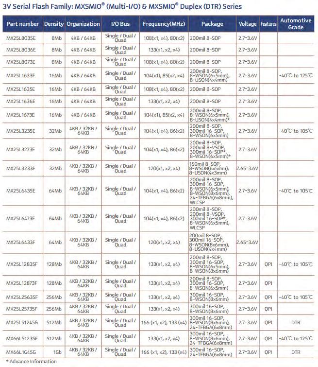
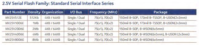
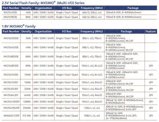
70 Page 70 List of Manufacturer Flash Memory IC Specification: MACRONIX (MX25 Series- Serial Flash Memory)

71 Page 71
72 Page 72
73 Page 73

74 Page 74 Winbond W25 Series- SPI Flash Memory W25X SpiFlash Family: 512Kbit to 4Mbit W25Q SpiFlash Family: 2Mbit to 256Mbit, superset compatible with 25X series. ** For more information in Serial Flash Memory IC specification, please refer to this file Flash Memory Specification List in the Bonuses Section B.
75 Page 75 Serial SPI Flash Memory Substitute/Compatible List Before use the list below, make sure the flash memory must fit with their 5 rules of how to substitute it. This list is use the SPANSION flash memory part number as a cross reference. But most of the time, inside the same column flash memory, it can use as a substitute or equivalent. But make sure that fit the rules on how to substitute it. For example, if the original flash memory is MX25L4005A, then we can use the substitute flash memory like MX25L8005A, S25FL004A, W25P40 & etc. If the spec likes this W25Q80BL & W25Q80BV, it will write as: W25Q80BL/BV. Density 512K-bit 1M-bit 2M-bit Spansion Flash Memory Substitute Flash Memory A25L512 AT25F512AN/AY/B, AT25BCM512B EN25F05, EN25P05 M25P05 MX25L512E PM25LD512C, PM25LV512 A25L010 AT25F1024AN/AY AT45DB011D EN25F10, EN25P10 M25P10, M25PE10, M45PE10 MX25L1005, MX25L1006E PM25LD010C, PM25LV010A SST25LF010A W25X10BV AT25F2048N, AT25DF021 EN25F20 M25P20, M25PE20, M45PE20 MX25L2005, MX25L2006E PM25LD020C, PM25LV020A W25X20BV
76 Page 76 4M-bit S25FL004K A25L040 AT25F4096/W/Y, AT25DF041A EN25F40, EN25Q40 F25L04UA, F25L004A GD25Q40 M25P40, M25PE40 MX25L4005A/C, MX25L4006E, MX25L4025C, MX25L4026E PM25LD040/C S25FL004A SST25VF040B W25P40, W25X040, W25Q40BL/BV, W25X40AL/AV/BL/BV 8M-bit S25FL008K A25L080 AT25DF081A EN25F80, EN25Q80A F25L08PA, F25L008A GD25Q80 M25P80,M25PE80 MX25L8005, MX25L8006E, MX25L8035E, MX25L8036E S25FL008A SST25VF080B W25P80, W25Q80BL/BV, W25X80AL/AV/AVS/V 16M-bit S25FL016K A25L016 At25DF161, AT25DQ161 EN25F16, EN25Q16 F25L016A, F25L16PA GD25Q16 M25P16, M25PX16, M25PE16 MX25L1605/D, MX25L1606E, MX25L1633E, MX25L1635D/E, MX25L1636D/E SST25VF016B, SST26VF016 W25Q16BV/CL/CV, W25X16AL/AV/BV/V 32M-bit S25FL032P A25L032, A25LQ032 AT25DF321/A, AT25DQ321A EN25B32, EN25F32, EN25P32, EN25Q32A/B F25L32PA/QA M25P32, M25PX32 MX25L3205D, MX25L3206E, MX25L3225D,
77 Page 77 64Mb-bit S25FL064K GD25Q64 MX25L3235D, MX25L3236D, MX25L3237D, MX25L6405 N25Q032 SST25VF032B, SST26VF032 W25Q32BV/V, W25X32AV/BV/V W25Q64BV, W25X64AV S25FL064P AT25DF641/A EN25B64, EN25P64, EN25Q64 M25P64, M25PX64 MX25L6405D, MX25L6406E, MX25L6436E, MX25L6445E, MX25L6446E N25Q064 SST25VF064C W25Q64BV/FV, W25X64BV/V 128M-bit S25FL128P MX25L12805D M25P M-bit S25FL129P S25FL256S S70FL256P EN25Q128 MX25L12865E, MX12845E, MX25L12835E N25Q128 W25Q128BV/FV MX25L25635E/F, MX25L25735E N25Q256 W25Q256FV 512M-bit S25FL512S MT25QL512AB MX66L51235F N25Q512A13/23/33/43/73/83 W25Q512JV 1G-bit S70FL01GS MX66L1G45G MT25QL01GB N25Q00AA 2G-bit MT25QL02GC For more information in Serial Flash Memory Substitute/Compatible list, please refer to this file Flash Memory Cross Reference Table in the V4.0 ebook Bonuses Section B download page.
78 What is LED Driver in LED TV? Page 78 The LED Driver in old LED TV service manual will call it as inverter, LED inverter & etc. But the latest LED TV service manual or training manual will call it as LED Driver board now. This LED Driver function like the LCD Inverter board, where the voltage input is low or small but output voltage is high. For example the LCD TV inverter input 24Vdc, but their output is about 1500VAC (depends on the inverter board design). For the LED Driver, its input 12Vdc (Vcc input for small inches LED TV) or 24Vdc and the output voltage is about 57Vdc, 120Vdc, 200Vdc and etc. But some of the small sizes LED TV (19, 22, 24 inches & etc) will direct generate voltage like 33V, 42V, 44V & etc, from the PSU secondary side supply to the LED strips/bars. This type of design, their brightness is cannot be adjust. Also some of them can t control the backlight on/off, when TV power on, the LED backlight is automatically on. So the LED Driver board/section their function is use to boost up the low voltage (DC voltage) and output to higher voltage (DC voltage). And it also included the typical features like backlight On/Off, Brightness control, circuit protection and etc. The Advantages of LED TV vs LCD TV Actually the LED TV has lots of the advantage when compare with LCD TV (CCFL or EEFL backlight). For example: energy saving save space (so the LED TV can manufacture more thinly than the LCD TV and etc. Some of the repairer will surprisingly why the latest 32 inches LED TV their Power Supply not included the PFC circuit in it! Because of the 32 inch LED TV their power consumption is below 85Watts or 70 Watts. For international standard, if the TV power consumption is 70 Watts or below it (China is below 85 Watts), their Power Supply (PSU) no need to built-in the PFC circuit in it. That s why lots of the latest 32 inches LED TV their selling price is so cheap. One of the reasons is, their PSU no need to built-in the PFC circuit and save the cost. It is because of the latest 32 inches LED TV their power consumption is just about 45Watts ~ 80Watts only.
 LED Driver board")
 Samsung BN44-00523A IP PSU")
79 Page 79 Types of LED Driver in LED TV The LED Driver board/section is separated to 3 types: 1) LED Driver board Samsung SSL460EL01 LED Driver Board 2) IP Board (Power Supply and the LED Driver built-in together) Samsung BN A IP PSU with LED Driver Board

 signal in LED Driver, it is a bit different than the LCD TV. Some LED Driver board P-DIM signal is call it as PWM, PWM_DIM and etc.")
80 Page 80 3) LED Driver built-in the T-con board Panasonic TC-L37DT30 LED TV- T-Con + LED Driver Board Most of the signal lines from Main board to LED Driver board/section are same as the LCD TV inverter. But some of them maybe their marking name/code in PCB board is different. For example the BL_ON signal, in some LED Driver it will show as DRV_ON, BLU_ON & etc. But their feature is the same, just to switch on the backlight system. For the P-DIM (Digital Dimming) signal in LED Driver, it is a bit different than the LCD TV. Some LED Driver board P-DIM signal is call it as PWM, PWM_DIM and etc. Where the LED Driver P-DIM (or similar name of it)
 brightness, its P- DIM signal voltage is about 5V, for Minimum (MIN) brightness of LED TV, it is about 0V. So the P-DIM signal functions like backlight dim control.")
81 Page 81 signal voltage range is about 0~5V (LG LED TV is about 0.2V~3.3V, Samsung LED TV is about 0.5V~4V). This signal is use to control the Brightness levels for backlight system. When the LED TV is Maximum (MAX) brightness, its P- DIM signal voltage is about 5V, for Minimum (MIN) brightness of LED TV, it is about 0V. So the P-DIM signal functions like backlight dim control. A Tip to Check the LED Panel If the LED TV left and right side has abnormal brightness or one side is darkness but another side is ok, then you can use this tip to checking the LED Panel. When you see the screen in front of TV, if a left side (a) has a problem, connect (2) cable at the (1) position and see the display result. If after changed cable position the TV (a) side has normal picture now, that s mean their LED Panel is ok (LED Blocks/Strips are normal), problem was in their LED Driver section. If after changed cable position, the TV side (a) still shows abnormal picture, for example darkness picture, that s mean their LED Panel side (a) LED blocks was defective and need to checking or replace it.
, T-CON board (the FPC connector) or LCD")
82 Page 82 Note: Remember below TV symptom, this type of symptom is not the backlight problem, but is their FPC cable (higher chances), T-CON board (the FPC connector) or LCD Panel.

83 LED Backlight Repair Tips for LED TV Page 83 Nowadays, lots of LED TV and LED Monitor are come to the work bench now. Most of the time LED TV display darkness problem is causing by the LED Driver board detected some abnormal status in LED strips/bars and shutdowns the LED backlight system. If the LED Driver not shutdown the backlight, it will show as one of screen position is darkness (top, bottom, left or right side). Normally this type of problem is causing by one LED light bulb opens in a LED strip/bar or block. So it will affect the other LED light cannot work. After that the LED Driver will shutdown the LED backlight or that. LED Block (1 block)


84 Page 84 LED Strip/Bar- Testing it with the Meter Diode Range (Or X10 for Analogue Meter If confirm that s the one LED light bulb was damaged, but the problem is we don t have the LED light bulb in stock so what can we do know? Just a simple method to repair this LED strip or block; Bypass this open circuit LED light bulb, so that the other LED light bulbs can receive the voltage supply from LED Driver. So just using a wire or jumper solder it in the open circuit LED light bulb as photo below, the LED strip or block can light up now. Assemble back the LED strip into LED Panel and the LED TV is working properly now.
85 How to Bypass LCD TV Inverter Board Shutdown Backlight System- Inverter IC List Page 85 SAFETY FIRST! If you re not understand about how to testing the electronic components, please DON T read this chapter. Please make sure that the Inverter board are no any components is shorted or leakage, if not it will burn Inverter board again. Again, this bypass method is just for troubleshoot the Inverter Board for components level repair and it is NOT to repair the Inverter Board. If you re bypassing the Inverter Board protection in this way, it may occur the fire in Inverter Board and the TV. Because when happen heavy shorted in the Inverter Board, it will not start-up the protection and causing the Inverter Board burn and TV maybe explode too! This method also calls it as: How to Bypass LCD TV Inverter OVP Protection. I had one article mention it before at: Most of the time, we will feel headache when we repair LCD TV with symptom display shutdown after few seconds, but they have normal sound. And sometime, you can use the strong flash light to see some content in the screen there. So it will confirm that the problem was in the backlight system (inverter board/section and their CCFL lamps). Before checking the backlight system, make sure that BL_ON/INV_ON signal (backlight on signal) and PDIM/DIM/ADJ (brightness control signal) are appears in the Inverter board/section. These both signals are come from the TV Main board and their normal voltage should be: BL_ON= 2.5V~5V and the ADJ= 0.8V~5V (5V is maximum brightness in the screen). Also you need to measure the voltage supply (Vcc) to inverter board is normal and stable; normally it is 24V or 12V.
86 Page 86 So with the above information, if all signals and voltage appears, we can know that this TV Display shutdown problem is in the inverter section or their CCFL lamp/s. For the CCFL lamp problem, normally it is leakage, broken or their wire contact with the lamp terminal has open. When checking the CCFL lamp, you need to open the lcd panel. But make sure to carefully remove their metal shield and other parts to prevent any damage on the lcd panel glass, especially their COF/TAB. For the inverter board/section, after checking all the suspicion components in it and still can t find any damage components then you will not sure what s the next step to check. So this chapter is to let you learn the method on different inverter IC for how to bypass their OVP Protection, so that we can see and check their inverter board and the lamps. Before using this method to testing the Inverter board and their CCFL lamps, make sure the Inverter board no any shorted or leakage components in it. This is a very important step to prevent any burn or explode in the board. When the TV is shutdown the backlight after few seconds, with the help of bypass Inverter IC protection, we can check the Inverter board in components level repair. After bypass the inverter IC OVP protection, these will happen in the TV: a) The backlight is lit now but we can see one of these CCFL lamp is off or weakness. * That s meant this CCFL lamp is damage and need to replace. Before replace, first check their both side of wire terminal connection is solder ok or not. If not then re-solder it and try to power on the backlight to see the problem solved or not, if not then just replace it with a working one. We can use the CCFL Lamp Tester to testing this lamp to confirm it is ok or not. * If the lamp is ok but this lamp still not lit, that s mean this CCFL lamp their circuit is abnormal, so that we can concentrate and quickly checking on this CCFL lamp circuit to find out what s wrong in it. b) If the TV backlight still shutdown after bypass their inverter protection.

87 Page 87 * This problem is because of the Inverter board has shorted or leakage component/s in the board. So that you need to confirm the components in Inverter board is not shorted or leakage. * Or the inverter IC pin is wrong to do the bypass protection and make sure to put the correct pin number of the inverter IC. This Inverter IC list is use to bypass the inverter board/section to shutdown their backlight system. For your information, before using it, make sure they are no any shorted or leakage components in the Inverter board or section there. LCD TV and LCD Monitor Inverter IC List Inverter IC Bypass Action To Do Protection Pin/s AAT StG (Short to Ground) AAT1101A/B/C 8 StG AAT StG AAT StG AT StG AT StG BA StG BA StG BIT3101/BIT3101A 2 & 15 OD BIT3102/BIT3012A 5 OD BIT OD BIT & 27 OD BIT OD BIT OD BIT OD DF StG DF StG
88 Page 88 FA & 16 StG (Remove both pins capacitor and then short to ground) FA & 10 StG FAN StG FP StG KA & 16 StG MB StG OZ960 2 StG OZ962 2 StG OZ965 4 StG OZ9RR 8 StG OZ OD (or remove their capacitor connected to this pin) OZ OD (or remove their capacitor connected to this pin) OZ9938 3(StG), 6 (OD) If pin 3 StG still can t bypass the OVP, then open the pin 6 (remove the component to this pin, so that this pin is not connect to the circuit like opened) OZ9939 3(StG), 6 (OD) Same as above SEM & 3 OD SP OD TL494 1 & 16 StG TL StG TL StG TL StG TL StG Remark: 1) StG = The Inverter IC pin/s Short to Ground. * Solder a wire to this pin/s and another side to the Ground (Cold Ground). 2) OD = Open or Disconnect the Pin/s from the circuit. * Solder out this IC pin/s and the pin/s is not connecting to the Inverter circuit/pcb board. Or remove the component connected to this pin, so that it is same like this pin is open circuit or disconnect from the inverter circuit.
89 The Method of How to Find LCD & LED TV Panel/Screen as a Replacement or Equivalent Page 89 When I m doing the support for my members, I m receiving lots of question about How can I replace the LCD Panel with different part number? The reason to replace it was because the LCD Panel is broken or damage. My answer to them is YES it can be replaced! But their question is how can I replace it? Normally I will not recommend this method to the TV repairers who are: 1) Don t have extra good or working LCD Panel in hand. 2) Don t know how to Self Test the PSU board + Backlight without connect it to Main Board. (This method was wrote in V ) 3) Don t know how to testing the voltage and signals in Main board, PSU board, Inverter Board and the T-Con board. In this chapter, I will let you know how to find a replacement for LVDS type LCD Panel. Actually the LCD Panel has two types, one is TTL (old model LCD TV) and another is LVDS type (Low Voltage Differential Signaling). But in this chapter I just show you how to choose the LVDS type LCD Panel as a replacement. Basic Knowledge of LCD Panel The LCD TV Panel has different types, but in this chapter I just reveal the LVDS type LCD & LED Panel. The important information we need to know for LCD Panel are: 1) Screen Size: * The LCD screen have many sizes, common use in Monitor & TV are 15~65 inches. But it also divides to different aspect ratio (DAR), they are: standard screen (4:3) and wide screen (16:9 or 16:10).
90 Page 90 2) Resolution: * LCD Panel resolutions are often quoted in terms of raw subpixels, misnamed pixels in manufacturer s specifications. Each real pixel includes one subpixels for each of three colors, so calling subpixels pixels inflates the claimed resolution by a factor of three. This bit of marketing obfuscation is calculated as horizontal resolution x vertical resolution x 3(HxVx3). For example: 1024 x768 x3= subpixels, but only full-color pixels. The LCD TV Panel have different resolution, they are: 3) Bits: Standard Definition (SD): 1366 x 768, 50Hz/60Hz, 2 Channels/Ports High Definition (HD): 1920 x 1080, 50Hz/ 60Hz, 4 Channels/Ports Full HD TV (FHD TV): 1920 x 1080, 100Hz/ 120Hz, 8 Channels/Ports Ultra HD (UHD): 3840 x 2160, 60Hz, 16 Channels/Ports And etc * The Color Depth or Color Support is sometimes expressed in Bits, either as the number of bits per sub-pixel or the number of bits per pixel. The LCD TV Panel has divides to 6 bits, 8 bits and 10 bits. Also have different channels for each bits, for example, 8 bits 2 channels (LVDS interface), 10 bits 4 channels and etc. 4) Input Voltage: * Normally the LCD TV Panel input voltage (actually is the T-con board Vcc input voltage) is using 5V or 12V, but some special part number of LCD Panel will use 18V too. For the small inches LCD Panel, it will use 5V or 3.3V as their Panel Vcc input voltage. 5) LVDS pins Description & Connector types * The LVDS pins description we can refer to their LCD Panel datasheet or product specification manual. * The LVDS interface has many types of connector design & number of pins. Normally it has 20 pins, 30 pins, 41pins, 51 pins and etc.
91 Page 91 Please refer to the Bonuses Section B Download Page to download the LCD Panel datasheet. Inside the datasheet you can find lots of useful information to help you to replace the LCD Panel correctly. The Methods to Find a Replacement of LCD & LED Panel If you want to successfully replace the LCD Panel, you must follow and check these information below before replace it: 1) LCD Panel input voltage (Important step and make sure the voltage input is same) * If the input voltage not same it will damage the T-CON board or/and LCD Panel! If LCD Panel is 12V type the Main board is supply 5V to it, the LCD Panel will not working only. If LCD Panel is 5V type but the Main board is supply 12V to it, the LCD Panel will damage or the T-CON board burn or both also gone. * Actually the LCD Panel voltage input type is depending on the T-CON board Vcc input, except the T-con board is built-in the LCD Panel. * Some repairer if they know how to use the DC-DC module, they can use it and put it in the T-CON board Vcc input and modify it. For example the DC-DC module like 12V to 5V output, but make sure their Ampere is match with the LCD Panel. For your information, some of the Main board is already built-in 12V and 5V Panel select jumper to choose. So this type of Main board can save the time and money to match the new LCD Panel. 2) LVDS connector type and LVDS pins configuration * Make sure to check the original and replacement lcd panel pins configuration from their panel datasheet. For the LVDS connector type we can use the eyes to look at it. If the LVDS connector type is different than the replacement LCD Panel, so need to find or buy a suitable LVDS cable with the same connector type. If their pins configuration is different, some LVDS cable can manually change or correct their pins position to the right position. For this step, we must refer to their LCD Panel datasheet to do it correctly. * Attention: Make sure their Vcc Voltage Input pin is put in the correct position, if not it will damage the LCD Panel!!
92 Page 92 3) LVDS Interface * LVDS interface format is divides to two: a) JEIDA Format b) VESA Format It is control by the SELLVDS or LVDS_SEL signal pin. Normally different LCD Panel manufacturer they have different method to setting it. For example, CHIMEI V315H3-LS2 LCD Panel, their JEIDA format is set SELLVDS to L (active Low) and VESA format is set SELLVDS to H (active High) or Open. To set this signal pin you can do like that: a) Active Low L = Short this pin to Ground. b) Active High H = Connect this pin to Main board 3.3V supply. c) Open = Remove this SELLVDS wire pin from the LVDS connector or Main board side connector. If this SELLVDS signal pin set it incorrectly, the TV display will show display distortion symptom or their display show reverse 180 degree. 4) Bits select for the LCD Panel * Most of the time, the LCD TV Panel is using 8 bits type. Some high definition LCD Panel is using the 10 bits type. The 10 bits type LCD Panel divides to two: a) The Bits cannot be select, only can working in 10 bits status. This type of LCD Panel cannot choose as a replacement for 8 bits type LCD Panel. b) The Bits is selectable by setting the signal pin in LVDS interface. As usual, it is set by Active Low, Active High or Open. So this type of LCD Panel can choose to working in 8 bits or 10 bits status. So this type of LCD Panel can use to choose as a replacement for 8 bits type LCD Panel. * If the 10 bits LCD Panel is use as a replacement of 8 bits LCD Panel and their display quality was not good and have some noise in the screen, please
93 Page 93 double check their Bit select control signal pin/s is set to the correct position (L, H or Open). 5) Backlight System * The backlight system has many types. If it is LCD type, they will use the CCFL or EEFL lamps. If the LED type, it is using the LED light bulbs with different voltage control in LED Driver. a) EEFL type: If the LCD Panel is using these EEFL lamps, then it is easy to replace their LCD Panel. Because it just use two connector or wire in their inverter board only. Most of their connector design is same, so it will let the repairer easy to replace it. b) CCFL type: If their replacement LCD Panel is using Single inverter board but original LCD Panel has Master and Slave inverter board, so their extra wires can bypass it. But make sure all the voltage cable, signals cables are connecting correctly. If the replacement LCD Panel is using master and slave inverter board but original LCD panel just has single inverter board, then you need to modify it and connect the extra cables to their slave inverter board there. Make sure their voltage supply and signals cables connecting correctly. * For LED type: Use their replacement LED Panel LED Driver board and make sure their voltage and signals cables are connecting correctly. If that is IP board type LED driver, then you need to make sure their output voltages is match the LED Panel, if not it will not work or maybe will damage the LED light bulbs or this LED Panel will not lasting long time use. * For more details in their control signals, please refer to the V3.0 LED LCD TV Repair Tips ebook. 6) LCD Panel Parameters * If these LCD Panel parameters not same, so this LCD Panel cannot be a replacement. a) LCD Panel Resolution not same, it is can t be a replacement. b) LCD Panel size not same, it is can t be a replacement. For example 32 inches is use the 32 inches LCD Panel as a replacement. The 31.5 inches cannot
94 Page 94 use the 32 inches LCD Panel as a replacement. Also their aspect ratio (DAR) must choose it correctly and it is divides to: 4:3, 16:9 or etc. * One more thing, some LCD Panel their thickness is different. If the original LCD Panel is thicker than the replacement, it is ok to replace. Because the TV cover can close it perfectly. But if the original is thin than the replacement, it is hard to say ok or not. Make sure the TV rear cover can close it perfectly, if not, then it is not recommend to replace it.

95 Page 95 The LCD Panel Replacement Tables This is a TCL manufacturer reference tables to let you easy to find the correct LCD Panel as a replacement. You can use these tables as a reference only, but you must compare their datasheet first before replace it.

96 Page 96

97 Page 97
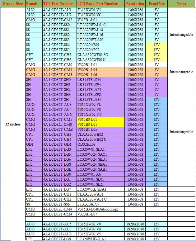
98 Page 98

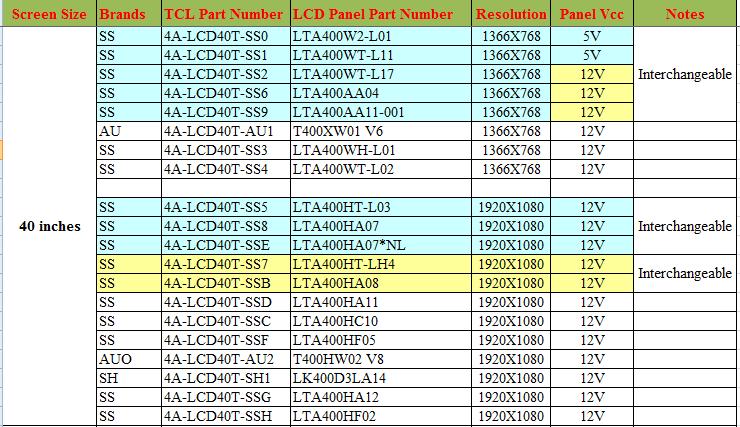
99 Page 99

100 Page 100
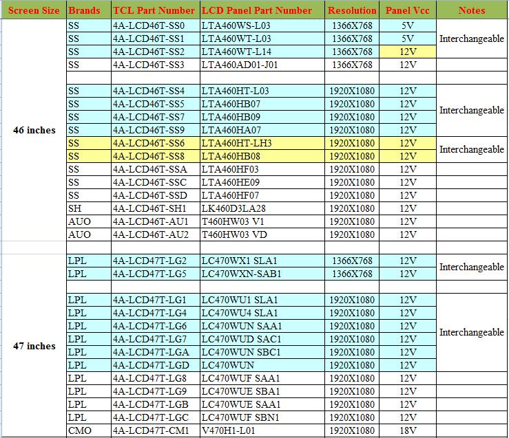
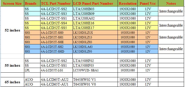
101 Page 101
102 Page 102 Remark: The above charts just for reference only and you must follow the The Methods to Find a Replacement of LCD & LED Panel. So you can find the correct LCD Panel to replace. One more thing, inside the 32 inches chart, the 320 is for 32 inches and the 315 is for 31.5 inches. So some of the LCD they will not match to replace, because the original TV Main board will not send out the correct LVDS format signal to it. But some LCD Panel like AUO T320XVN02-A, it is 31.5 inches type not the 32 inches. So it is suggest referring to their datasheet for more details. Another thing is their Panel voltage input (Vcc). Besides the 5V and 12V, some part number of LCD Panel have different Vcc input, for example the CMO V420H1-L01 it is using the 18V. So be careful about it, if not it will damage the LCD Panel again.


103 The T-CON Board Page 103 Nowadays, the LCD LED Panel Timing Control section is not only in the T- CON board, but it also built-in the LCD Panel and the Main board. The Timing Control section and their DC-DC circuit have higher repair rate in LCD LED TV. If the T-CON was built-in the LCD/LED Panel, then lots of TV repairer will direct return the TV to customer and told them this TV is beyond repair or not worth to repair it, because it is the LCD Panel problem. The T-CON Board The Timing Control Section & DC-DC Circuit Built-In the LCD Panel

104 Page 104 The Timing Control Section and DC-DC Circuit are Built-in the Main Board So if you have enough knowledge on how the Timing Control and their DC-DC circuit works, then it is no problem to troubleshooting and repairing it. Actually the small sizes LCD/LED Panel, their Timing Control and the DC-DC circuit were built-in the Panel long time ago. And we call this board as LCD Controller Board. But they are same thing, just the name is different. For more basic knowledge of T-Con Board, please refer to the V3.0 ebook for more details. If we know how the T-con board work and also know how to troubleshoot it, then it will help us to repair the T-con board or LCD Panel easily. Another problem to repair the T-con board/section is their spare parts. So we can search the parts online or find the part in the junk T-con boards.
105 Page 105 The Importance of Checking GAMMA & Vcom Voltage in T-CON Board If you re repair LCD or LED TV, or even the LCD/LED Monitor, the Timing Control section is important and we must figure out how it work and how to troubleshoot it. Some repairer will say the T-CON board is cheap to replace, so no need to learn more about it. But the problem is not all LCD/LED TV and Monitor are using the T-CON board, especially the LCD/LED Monitor and Laptop LCD/LED Panel their Timing Control section are built inside the Panel or call it as LCD Controller. I found that lots of the LCD/LED Monitor and Laptop Panel/Screen problem can be repair but lots of the repairers just throw away it into the rubbish. And then replace a new Panel or just return back the Monitor to customer and say beyond repair or not worth to repair. So we must learn how the T-CON work and the method to troubleshoot it. No wonder the Timing Control section is design inside the Panel, T-CON Board or Main Board, so that we know how it works and where to checking their circuit. How the GAMMA channels voltages and VCOM voltages generated? When the T-CON board (for example V315B3-C01 T-con board) DC-DC circuit generated the VDA voltage, this voltage is use to generate the GAMMA and VCOM voltages through U6 (HX8915A). This HX8915A is a 14+1 channels buffer IC, the 14 is for 14 x GAMMA channels and another 1 is for 1 x VCM channel use. This VDA voltage will go to: 1) VDA voltage go through the R335 resistor to generate the VDA_OP voltage for GAMMA IC U6 (HX8915-A, similar with the AS15 series IC) Vcc input use.
106 Page 106 2) The VDA voltage also goes to D1 & D4 to generate the VREF (Voltage Reference) voltage and send it to their voltage divider resistor circuits. Normally the VREF circuit just uses the D1 (KA431 type component) to generated VREF voltage only. This VREF voltage normally is about 12.5V. But different design it has a bit different on it. 3) For this T-CON board V315B3-C01, the VDA voltage also sends to U2 to generate the VSCM voltage and then send to U6 to generate the VCM (Vcom) voltage. Normally this VCM voltage is generated by the VREF circuit. The VREF output line go through two resistors as voltage divider resistor circuit and get the VSCM voltage, and then send it to U6 (HX8915A) to output the VCM (Vcom) voltage. This Vcom voltage will send to the LCD Panel glass.
107 Page 107 Note: The Vcom (VCM, Common Voltage) voltage is about half of the VREF voltage. Remember this rules, the VCM voltage is about half of the VREF voltage. If the Vcom voltage not stable or their voltage is out from the original values, the TV display will abnormal or their brightness problem. After the VREF voltage was generated, it will send to 2 groups of resistors voltage dividing circuits. These 2 groups of resistors voltage divider resistor circuits will divided the VREF voltage to 14 channels different voltages call it as VS1~VS14 GAMMA voltages. But these voltages can t direct send to the LCD Panel use, they need to send it to the buffer IC U6 (HX8915A or AS15 IC), and then it will output the GAMMA voltages GM1~GM14. These GAMMA voltages will send to the LCD Panel Source Driver board.
 voltages were generated through the circuit")
108 Page 108 Finally the GAMMA voltages and the Vcom (VCM) voltages were generated through the circuit below:

109 Page 109 What will happen when Vcom (Common Voltage) voltage missing? When the Vcom (VCM) voltage is missing, the Panel display will become white and it is looks like the negative picture. If this is happen to your TV, you need to check their output voltage at the T-CON board. Normally their marking code at PCB board is Vcom, VCM or etc. If you re not sure what voltage values is normal for the Vcom, never mind, do you remember the Vcom voltage is about half of the VREF voltage. So you can find the VREF voltage to measure it and then you can roughly know what the voltage values for the Vcom voltage are.

110 Page 110 How to know the GAMMA channels voltages normal or abnormal? As you know that the GAMMA channels voltages when different T-con board or Panel, it has different channels in it. Normally is about 14 channels, 18 channels or above 20 channels. But all these GAMMA channels voltages has one important rules, that is The GAMMA Channels Voltage their voltages order is from high to low or low to high! For example good GAMMA Voltages from high to low (V315B3-C01T-CON): CM V CM8-6.27V CM V CM9-5.99V CM V CM V CM V CM V CM V CM V CM6-9.88V CM V CM7-8.21V CM V Their voltages order high to low will looks like this: 15.17V, 14.16V, 11.99V, 11.40V, 10.67V, 9.88V, 8.21V, 6.27V, 5.99V, 5.20V, 4.26V, 3.36V, 1.35V, 0.73V
 11.5V, 10V, 8V, 3V, 7.06V, 6.75V, 6.03V, 5.73V, 4.88V, 4.02V, 3.")
111 Page 111 If you found the GAMMA Channel Voltages like these, that s mean the GAMMA circuit is failure and you need to check it. If not find any components failure, just try to replace their buffer IC like AS15, HX8915A & etc. The Example of Bad GAMMA Voltages: 1) 11.5V, 10V, 8V, 3V, 7.06V, 6.75V, 6.03V, 5.73V, 4.88V, 4.02V, 3.66V, 2.81V, 1.35V, 0.53V 2) 0.78V, 1.45V, 2.28V, 3.88V, 4.34V, 5.02V, 5.78V, 6.67V, 9.23V, 8.95V, 8.55V, 9.46V, 10.78V, 12.3V 3) 15.02V, 14.52V, 11.38V, 10.01V, 9.47V, 8.95V, 8.03V, 7.55V, 6.68V, 5.62V, 4.03V, 2.76V, 5.13V, 0.68V You can check the GAMMA voltages on the T-CON board and their marking code is GM, CM, PGM or etc. Besides the DC-DC circuit has higher failure rate in T-Con board, the second is the GAMMA circuit. So if the GAMMA voltages abnormal, it will cause the TV display color abnormal, display noise in the display background or etc.

112 Page 112 Why After Replaced the AS15-G IC to AS15-HG The TV Still Has Problem? The AS15 series IC is a 15 x Op Amp IC. It is Op-Amp, 14 Op-Amp is for the GAMMA use and another one is for VCOM. Some TV repairer said after replace the AS15-HF to AS15-HG, the TV screen problem not solve or more serious than before. Sometime after replace the AS15 IC, the TV display is ok about 20 minutes, then whole screen change to nearly white screen about 3~5 seconds, and then screen back to normal about 5 minutes and then changed to white screen again. So the screen is non-stop to change like that, and the new replace AS15 IC can feeling extremely heat. Are the AS15G and AS15HG compatible? But when change to another batch of AS15 IC, the T-Con board problem solved! Actually the AS15F, AS15G, AS15-HF & AS15-HG all are compatible and equivalent to use! But the problem is lots of the AS15 series IC in the market now is not in good condition or call is as recon IC. Especially the cheapest price of AS15 IC, this type of IC mostly has higher chances is not a good IC.

113 Page 113 The above picture of AS15-F IC, this batch of IC: 0452A, we found that after change to this IC, the IC is extremely heat on the T-con. Finally found the AS15-HG IC batch no: 1032B, after replace AS15-F with this AS15-HG, the TV display problem solved and the IC temperature is just feeling warm only. Even the AS15-HG batch no: 1210C also not good to use. Note: I have a tip for this AS15 series IC or even the AS19 series also same. When they replace the equivalent or compatible AS15 IC on the T-con board, if the finger can feel AS15 IC surface is very hot, but the display is ok, then I will recommend change another AS15 IC. Because it will cause this T-con board cannot last long to use. Or the AS15 IC is extremely heat on the IC surface and their TV display also abnormal, then direct removes it and replaces another one to try again. So lots of the TV repairer if they facing this problem before, hopefully they know what can do now and don t confuse about it again.
 T-CON Board P/N: CMO V315B1-C01 (V315B1-L01) D1= 431W N6= 3.3V (LDO) N7= 2.")
114 Page 114 Various of T-CON Board Voltage Testing Points and Their Symptom When Voltage Fail to Appears This chapter will provide the T-CON Board/Section of components part number and their good testing point voltage values. 1) T-CON Board P/N: CMO V315B1-C01 (V315B1-L01) D1= 431W N6= 3.3V (LDO) N7= 2.5V (LDO) Q2= 4422 U1 & U2 = EM636165TS U3= CM2681A U5= 24LC128 U6= AS15-G UP1= AT1380AP (pin1= 0.5V, pin2= 0, pin3= 5V, pin4= 0V, pin5= 2.6V, pin6= GND, pin7= 0.36V, pin8= 0.19V)
 pin1 (C)=12V, pin2 (R)= 2.4V and pin3 (A)= GND.")
115 Page 115 VCM= 5.9V, VREF= 12V, VDD= 3.3V, VGH= 19V, VDA= 13.5V, VGHP= 24V, VGL= -5.6V When U6 (AS15-G) fail, the TV will occur symptom like: display distortion, no display, TV auto shutdown & etc. The AS15 IC can use HX8915-A as a replacement at V315B1-L01, V315B3-L01, V315B1-L08 and V315B3-L04 T- CON Board. The D1 (431W) pin1 (C)=12V, pin2 (R)= 2.4V and pin3 (A)= GND. When D1 damage, U6 (AS15-G) will no VREF voltage output and causing the TV no display symptom. Note: 431W and M431A is not same pin position, their pin1 & pin2 are opposite. So be careful when using the M431A as a replacement. But we can direct replace it with the N1B marking code 431 component on the inverter board. 2) T-CON Board P/N: CMO V420H1-C07 (V420H1-L07) D1= N1B (can replace with 431W) LP2= 3.3V U2= 24LC128, U3& U4= EM638325TS U5= i7822 (pin1&2= VST 0.6V, pin3= 0.6V, pin4= GND, pin5= 5.8V, pin6&7- VCOM= 5.5V, pin8-vda= 13.7V) U7= i7868a, U16= CM2679B/C/D, UP1= TPS65161, UP8= 2.5V (LDO)

 is defective.")
 damage, or the voltage supply: 2.5V, 3.3V, 13.7V, 18V, - 5.")
116 Page 116 VDD= 3.3V, VDA= 13.7V, VGH= 18V, VGL= -5.5V, VCOM= 5.5V, GVON= 0V, GVOFF= 2.6V, VAA= 13.7V, VGHP= 20V When U16 is using the CM2679D, the UP8 is use the 1.8V LDO. For the CM2679B &C is use the 2.5V LDO. The LVDS Input Resistors for CM2679B/C their good ohm values (between the resistor and GND) is about 400 ohm. If that is CM2679D is about 500 ohm. If the R149 ohm values increases, normally this is because of the U16 (CM2679) is defective. Another design of the V420H1-C07: I7868A (same as i7868a) and AS19 IC can be interchangeable in CMO 37 inches and above LCD/LED Panel, like HX8919-A. If U1 (CM2679B) damage, or the voltage supply: 2.5V, 3.3V, 13.7V, 18V, - 5.5V and 12V missing, the TV will no display, but the backlight is lit. If the TV screen is abnormal display, it could be their U1 (CM2679B) damage or dry
 T-CON Board P/N: CMO V370H1-L0A (35-D013142 [FHD-CM]) C= CP28, DP7 or Q9 damage will causing the 23V no output and the TV will No Display symptom. D1= 431 LP2 (Coil)= 3.")
117 Page 117 joins, GAMMA Correction IC i7868 or the T-CON board voltage supply abnormal. When the VCOM= 5.5V voltage is missing, the TV display will change to white or looks like negative picture. 3) T-CON Board P/N: CMO V370H1-L0A (35-D [FHD-CM]) C= CP28, DP7 or Q9 damage will causing the 23V no output and the TV will No Display symptom. D1= 431 LP2 (Coil)= 3.3V U1= 8902 (pin5 output VCOM= 5.5V) U5= 24LC128 U6= CM2677B U8 & U11= EM U14= AS19-G UP2= FPS138, UP3= MAX1858, UP8= 2.5V (LDO), UP9= 2.5V (LDO) VGHP= 23V, GVON= 0V, GVOFF= 2.6V, VGH= 21V, VGL= -5.5, VDA= 13.5V, VDDC= 3.3V, VREF=12V, VCOM=5.5V
 dry joins or U14 (AS19-G) damage will causing the TV display distortion problem.")
118 Page 118 When the voltage supply 13.5V & 23V their filter capacitor is leakage or shorted, the TV will No Display. Also for the other voltage supply like VDDC- 3.3V, VREF-12V, VDA-13.5V, VGH-21V, VGL=-5.5V, UP8&9=2.5V if missing, the TV also No Display. If the U6 (CM2677B) dry joins or U14 (AS19-G) damage will causing the TV display distortion problem. When the U1 (8902) damage and causing the VCOM 5.5V missing, the TV display will become white screen. 4) T-CON Board P/N: Chung Hwa CPT370WA03C IC101= VTII8872, IC102 & IC103= EM636165TS, IC105= 25F12, IC201= E3A (same as 431), IC202= ISL24003, IC501= ISL976, L502= 3.3V Q501= 576RE (pin1,2,5&6 is output, pin3 is a control pin, pin4= 13.7V input) VREF= 12V C= This 13.7V line filter capacitors always short circuit in this T-CON board. Looks like a common fault in this T-CON board. CNSR2 & CNSL2=> pin7 &8= -6.2V, pin9&10= 24V, pin11&12= 13.7V, pin 13&14= 6.5V, pin15&16= 3.3V, pin 17&18= 13.7V
 IC104= IS42S32200 IC301= M431A IC302, IC303, IC304, IC305, IC306= 2904 U501= 8728E VREF= 12V C537= 24V R528= 13.7V R545= -6.2V CNSR2 & CNSL2= PIN7&8= -6.")
119 Page 119 5) T-CON Board P/N: Chung Hwa CPT320WA01C D501= 3.3V IC101= VE606RL (FPDB7352CXAVV) IC104= IS42S32200 IC301= M431A IC302, IC303, IC304, IC305, IC306= 2904 U501= 8728E VREF= 12V C537= 24V R528= 13.7V R545= -6.2V CNSR2 & CNSL2= PIN7&8= -6.2, PIN9&10= 24V, PIN11&12= 13.7V, PIN13&14= 6.5V, PIN15&16= 3.3V, PIN17&18= 13.7V When one of these IC: IC302, IC303, IC304, IC305 or IC306 defective, the TV display will be darkness. This IC101 has higher damage rate in this T-Con board. For example, their symptom likes no display and display distortion.

120 Page 120 6) T-CON Board P/N: HV365WXC-200 LCD Panel: ChangHong M370X12-E1-B LED Panel Testing the working voltage with Changhong LED37B1000C LED TV and the screen is no display with blue screen only.
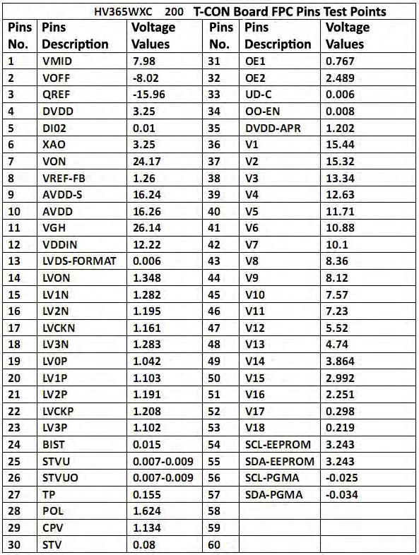
121 Page 121
 Symptom: Display Color Problem like Oil Painting and the Display also Reverse 180 degree now. Repair/Solution: Regarding this type of symptoms, lots of the TV repairer will give up to repair it.")
122 Page 122 Repair Case Study for T-CON Board Model: Samsung 43 inches LED TV (This is a fake Samsung LED TV!) Symptom: Display Color Problem like Oil Painting and the Display also Reverse 180 degree now. Repair/Solution: Regarding this type of symptoms, lots of the TV repairer will give up to repair it. Because they will think it is their LED Panel (or T-CON Board) problem. Also this TV is a fake Samsung 43 inches LED TV, their repair information is hard to find to compare to the original TV manufacturer. So this TV is send by another TV Repairer and he also said if can t repair it doesn t matter, because it is not the original Samsung LED TV. This TV cover is looking like Samsung, but inside the TV, it is just using an OEM brand TV Main board only.
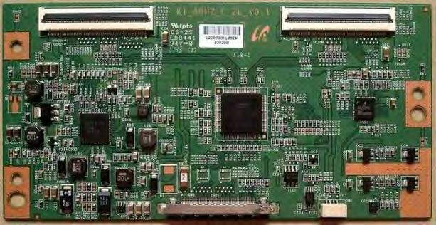

123 Page 123

124 Page 124 After analysis this LED TV symptoms, I suspect it was the T-CON board or Main board problem. Why I m not suspecting the LED Panel? Because I know that the display reverse problem is causing by their SELLVDS or Rotation signal set as incorrect by Main board or the T-con board problem. Before starting to repair this LED TV, I will checking their Service Mode setting or just try to do the firmware upgrade for it. But the problem is, this is not the branded TV, so we don t have the enough information to find their service manual and then know how to login to their Service Mode. Also we don t have this Main board good firmware to do the upgrade too. So what can I do now? Actually for this type of OEM TV Main board, they have the part number in the Main board there. Finally found the Main board part number: TSUMV59UXS_V1.1 as picture below:
 Press MENU, the screen is showed the Menu OSD there b) Press number buttons: 1147 and the screen")
125 Page 125 Found the information for this Main board. This is a ROWA V59 series Main board and its Service Mode login step is using the remote control: a) Press MENU, the screen is showed the Menu OSD there b) Press number buttons: 1147 and the screen will show another OSD Menu c) Select: General, Setting, Login d) Select LVDS MAP adjust 1, 2, 3, 4 16 after adjusted ok, press the EXIT button to log out the Service Mode. Finally this TV problem was solved and it is working properly now.

126 Page 126 T-CON Board Repair Tips 1) Model: ChangHong LT26830EX LCD TV Symptom: Display Distortion Problem Repair/Solution: Normally this type of display symptom is causing by the Main board, LVDS cable or T-CON. So start to check their Service Mode Panel setting. Use the remote control press and hold the MUTE button about 3 seconds, then press TV Key board MENU button, then it will login to the Service Mode successfully. Changed the Panel setting to the correct Panel part number, after that, use the remote control to power off the TV. Power on again the TV, the TV display distortion problem is ok now.

127 Page 127 2) Model: Changhong LT42729F LCD TV Symptom: Display Distortion Repair/Solution: Again this TV is also same display distortion problem. So again we need to login to their Service Mode to adjust the Panel setting. Method to login to the Service Mode: In TV Mode, use the remote control press buttons: MUTE --MENU 6, 1, 1, 5. So it will login to the Service Mode successfully and go to Panel setting there to change it to the AU_T420HW04 (the TV LCD Panel part number). After change the Panel setting, this TV is ok now.


128 Page 128

129 Page 129 3) Model: Hisense LED39K310X3D, LED39K316, LED39K320 & LED39K321 LED TV Symptom: The TV is White Screen Problem The TV is White Screen problem, but the sound is normal. This LED TV is using the CMI V390HK1-LS5 LED Panel and their T-CON board part number is V236H3-CS3-C. Repair/Solution: This is a common fault in this LED Panel. Their V390HK-LS5 Rev.C7, Rev. C8 & Rev. C9 also have the same symptom. Their solution is removed the U3 (MX25L2026E) flash memory and using the programmer to program a good firmware in it. After that, solder back this flash memory to U3. After replace the U3 firmware, the LED TV can show the perfect display now.

130 Page 130 4) Model: Konka LC22E561B LCD TV Symptom: Display Distortion Problem Repair/Solution: After dismantle this LCD TV and found that their Timing Control is built-in the Main board there. When checking the Main board and saw that their GAMMA IC is using this AS15-G IC, so measure their GAMMA output voltage. Found that one of their GAMMA voltage output was abnormally. So direct replace this AS15-G IC with this AS15-F and the TV problem solved!
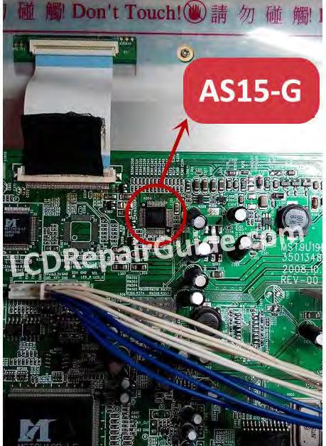
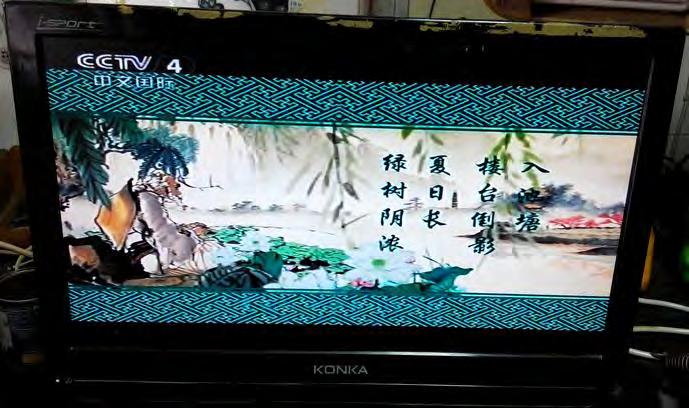
131 Page 131

132 Page 132 5) Model: Sharp LCD32WXN LCD TV Symptom: Negative Display The screen brightness is high and the display no gray scale in it. Repair/Solution: After analysis the picture above and found that this type of symptom is causing by the T-CON board. The screen is just show negative display only and no any gray scale for the picture. Most of the time, this type of problem also cause by their T-con Board GAMMA or Vcom circuit. This LCD TV T-con section was built- in the LCD Panel, so need to remove their metal bracket to checking their T-con section. First check the VDD_R has 14.9V, after that checking the VR_VCOM has 0V! So this voltage values is abnormal for the VCOM voltage, because the Vcom voltage normally is about half of the VDA voltage. Measure the VR1 pin 1 (one of the R276 pin), its voltage still 0V, so suspect the VR1 is open circuit. Remove the VR1 (marking as 23 ) and using the Multimeter measure it and found the VR1 was opened circuit.
.")
133 Page 133 VCOM Voltage Circuit Since the VR1 is marking as 23, that s mean their ohm values is 2K ohm. Because of the VR1 center pin position is in the middle, that s mean, the ohm values is about 1K ohm (half of the 2K ohm). So you can replace a 1K ohm resistor to VR1 pin2 & pin3, but make sure the VR1 position pin1 & 2 is shorted. After replace the VR1, VR_VCOM has output 7.54V there and the TV problem was solved. 6) Model: Sharp LK315T3LZ54 LCD Panel Symptom: Tips for Display Reverse Problem T-con Board: CPWBX3562TPXF

134 Page 134 Repair/Solution: Actually this type of symptom is we can repair it through: a) Software control: Some TV is allowed to login to the Service Mode and change their setting to cure this problem. b) Hardware modify: If the TV not provide the software control, then we can modify the hardware, especially the T-CON board LVDS connector pin27 & 28.

135 Page 135 **The other Screen Problem repair tips, please refer to V2.0 & V3.0-LED LCD TV Repair Tips at: *For the complete learning LCD Television repair, highly recommend you join the LCD Television Repair membership site as below:
136 Page 136 Conclusion: I strongly suggest you to print out this e-book and binding it as a book for easy reference. If you have questions about LCD/LED Television Repair, please do not hesitate to send me an at: fastrepairguide@gmail.com I wish you all the best and look forward to hearing your success story. Enjoy repair! To your success, If you want to buy the Test Equipment, Tools and Spare Parts please visit to the page here: All these tools and equipment will help you in troubleshooting and repairing the electronics devices.


137 Recommended Other EBooks to Learn LCD TV Repair Page 138 The information below will help you learn how to repair your LCD TV successfully. Click the Icon below to visit the website: Beginner & Intermediate Intermediate & Advanced
Preview of the book Testing Electronic Components. Brought to you by Jestine Yong. http://www.testingelectroniccomponents.com
 Preview of the book Testing Electronic Components Brought to you by Jestine Yong http://www.testingelectroniccomponents.com You cannot give this E-book away for free. You do not have the rights to redistribute
Troubleshooting And Repairing ATX Power Supply
 Troubleshooting And Repairing ATX Power Supply Brought to you by Jestine Yong Http://www.PowerSupplyRepairGuide.com I hope that you have enjoyed the short report of The Easy Way To Understand Switch Mode
Troubleshooting Tips Lifestyle SA-2 & SA-3 Amplifier. Troubleshooting Tips
 Troubleshooting Tips Lifestyle SA-2 & SA-3 Amplifier Refer to the Lifestyle SA-2 & SA-3 Amplifier service manuals, part number 271720 for schematics, PCB layouts and parts lists. Preventative Repair Measures
JUSTOP Smart TV Player With Android 4.0. User Manual
 JUSTOP Smart TV Player With Android 4.0 User Manual User s Notice This manual is provided as is without warranty of any kind, either express or implied, including but not limited to the implied warranties
COLOR TFT LCD MONITOR. User Manual
 COLOR TFT LCD MONITOR User Manual GENERAL INFORMATION Thank you for choosing our TFT LCD(liquid crystal display) monitor. This product employs integrate circuits, low power consumption, and no radiation
User Guide. HDMI Active Cable Extender. DVI-7370c
 User Guide HDMI Active Cable Extender DVI-7370c TABLE OF CONTENTS SECTION PAGE PRODUCT SAFETY...1 PRODUCT LIABILITY...1 1.0 INTRODUCTION...2 2.0 SPECIFICATIONS...3 3.0 PACKAGE CONTENTS...4 4.0 CONNECTING
Notice. Reverse engineering and disassembly are prohibited.
 Notice The information in this document is subject to change without notice. Every effort has been made in the preparation of this document to ensure accuracy of the contents, but all statements, information,
Home Theater PC Chassis
 Home Theater PC Chassis Model: HTPC 180 BA & SA Color: Black & Silver Quick Installation Guide (U.S. & Canada Only) Version 1.0 DISCLAIMER No warranty or representation, either expressed or implied, is
AN588 ENERGY HARVESTING REFERENCE DESIGN USER S GUIDE. 1. Kit Contents. 2. Introduction. Figure 1. Energy Harvesting Sensor Node
 ENERGY HARVESTING REFERENCE DESIGN USER S GUIDE 1. Kit Contents The RF to USB Reference Design contains the following items: Si1012 Energy Harvesting Wireless Sensor Node EZRadioPRO USB Dongle ToolStick
PRODUCTIVITY THROUGH INNOVATION 600 CONTROL DIRECT DRIVE TECHNICAL/OPERATION MANUAL
 Rev. D PRODUCTIVITY THROUGH INNOVATION 600 CONTROL DIRECT DRIVE TECHNICAL/OPERATION MANUAL 10 BORIGHT AVENUE, KENILWORTH NEW JERSEY 07033 TELEPHONE: 800-524-0273 FAX: 908-686-9317 TABLE OF CONTENTS Page
ECEN 1400, Introduction to Analog and Digital Electronics
 ECEN 1400, Introduction to Analog and Digital Electronics Lab 4: Power supply 1 INTRODUCTION This lab will span two lab periods. In this lab, you will create the power supply that transforms the AC wall
2GB MP3 Player USER GUIDE
 DO NOT FORMAT UNIT under FAT. 2GB MP3 Player USER GUIDE Jazwares, Inc. 2010 CONTENTS Please read the instructions along with the MP3 Player carefully before you use it, so that you can operate it conveniently.
User Manual. September 18, 2007. Copyright 2004-2007 Thomson. All rights reserved.
 User Manual September 18, 2007 Copyright 2004-2007 Thomson. All rights reserved. Notices and Warranties Notices & Warraties Copyright Regulations It is illegal for anyone to violate any of the rights provided
4 Troubleshooting Your Projector
 4 Troubleshooting Your Projector If you experience problems with your projector, see the following troubleshooting tips. If the problem persists, contact Dell (see Contacting Dell on page 57). Problem
Point of view HDMI Smart TV dongle Mini RF Keyboard
 Point of view HDMI Smart TV dongle Mini RF Keyboard English Contents Contents... 1 General notices for use... 2 Disclaimer... 2 Box Contents... 2 1. HDMI TV dongle... 3 1.1. Product display... 3 1.2. Instructions
Taurus Super-S3 LCM. Dual-Bay RAID Storage Enclosure for two 3.5-inch Serial ATA Hard Drives. User Manual March 31, 2014 v1.2 www.akitio.
 Dual-Bay RAID Storage Enclosure for two 3.5-inch Serial ATA Hard Drives User Manual March 31, 2014 v1.2 www.akitio.com EN Table of Contents Table of Contents 1 Introduction... 1 1.1 Technical Specifications...
Troubleshooting. Before you call for assistance
 Do not open the LitePro case! Opening the case may cause electric shock! Except for the projection lamp, there are no userserviceable parts inside. If you are having problems with your LitePro, read through
Modifying the Yaesu FT-847 External 22.625 MHz Reference Input
 Modifying the Yaesu FT-847 External 22.625 MHz Reference Input David Smith VK3HZ Introduction This document describes the modification of an FT-847 to allow an external 22.625 MHz Reference oscillator
Mini Effect Gizmo. User s Manual. RJM Music Technology, Inc.
 Mini Effect Gizmo User s Manual RJM Music Technology, Inc. Mini Effect Gizmo User s Manual Version 1.3 September 26, 2013 RJM Music Technology, Inc. 2525 Pioneer Ave #1 Vista, CA 92081 E-mail: support@rjmmusic.com
THE R551N RECEIVER FAQ FAULT FINDING THE REDIFON COMMUNICATIONS RECEIVER R551N. Date: October 10th 1995 by: Jan Verduyn G5BBL
 THE R551N RECEIVER FAQ FAULT FINDING THE REDIFON COMMUNICATIONS RECEIVER R551N Introduction: Date: October 10th 1995 by: Jan Verduyn G5BBL Recently a number of Redifon R551N receivers have appeared on
November 1995 QST Volume 79, Number 11
 Lab Notes Prepared by the ARRL Laboratory Staff (e-mail: tis@arrl.org) ELECTRONIC TROUBLESHOOTING By Ed Hare, KA1CV, ARRL Laboratory Supervisor Q: Someone just gave me a collection of used amateur equipment,
K8025 VIDEO PATTERN GENERATOR. Check the picture quality of your monitor or TV, ideal for adjustment or troubleshooting.
 K8025 ILLUSTRATED ASSEMBLY MANUAL H8025IP 1 VIDEO PATTERN GENERATOR Check the picture quality of your monitor or TV, ideal for adjustment or troubleshooting. Forum Participate our Velleman Projects Forum
How to read this guide
 How to read this guide The following shows the symbols used in this Quick start guide with descriptions and examples. Symbol Description Example P oint Reference Caution [ ] This symbol explains information
ITC-BTTN Cellular Bluetooth Gateway. Owner s Manual 1
 ITC-BTTN Cellular Bluetooth Gateway Owner s Manual 1 2 Table of Contents Introduction...3 Package Contents...3 XLink Connections Diagram...4 Setup...5 Pairing your Bluetooth Cell Phone to the XLink...6
LM 358 Op Amp. If you have small signals and need a more useful reading we could amplify it using the op amp, this is commonly used in sensors.
 LM 358 Op Amp S k i l l L e v e l : I n t e r m e d i a t e OVERVIEW The LM 358 is a duel single supply operational amplifier. As it is a single supply it eliminates the need for a duel power supply, thus
USB 2.0 4-Port Extender Kit
 USB 2.0 4-Port Extender Kit 500072 MuxLab Inc. 2014 94-000760-A / SE-000760-A Table of Contents 1. Introduction... 2 2. Features... 2 3. Specifications... 2 4. Package Contents... 3 5. Physical Diagram...
Daker DK 1, 2, 3 kva. Manuel d installation Installation manual. Part. LE05334AC-07/13-01 GF
 Daker DK 1, 2, 3 kva Manuel d installation Installation manual Part. LE05334AC-07/13-01 GF Daker DK 1, 2, 3 kva Index 1 Introduction 24 2 Conditions of use 24 3 LCD Panel 25 4 Installation 28 5 UPS communicator
MAINTENANCE & TROUBLESHOOTING
 MAINTENANCE & TROUBLESHOOTING This section describes how to: clean the lens clean the fan intake filter replace the projection lamp replace the batteries in the remote control use the Kensington lock feature
Online UPS. PowerWalker VFI 1000R/1U
 Online UPS PowerWalker VFI 1000R/1U Manual Uninterruptible Power Supply System Table of Contents 1. Important Safety Warning... 1 1-1. Transportation... 1 1-2. Preparation... 1 1-3. Installation... 1 1-4.
Contents Contents Contents Overview Charging your headset Wearing the headset Powering on the headset Connecting your headset for dictation
 1 Contents Contents Contents 2 Overview 3 Charging your headset 4 Wearing the headset 4 Powering on the headset 4 Connecting your headset for dictation 5 The adapter 5 Adjusting your computer's audio settings
AK10 INSTRUCTION BOOK INSTRUCTION MANUAL
 AK10 INSTRUCTION BOOK INSTRUCTION MANUAL CONTENTS Getting started _01 Components Names of parts Power supply management 02 03 04 Using _02 Connecting iphone/ipod and listening to music Using the USB DAC
Glolab Talking Phone Dial Monitor
 Introduction The detects the tones generated when numbers are dialed on your touch tone telephone and speaks the numbers that were dialed. This verifies that you dialed the correct number and is especially
Kinivo 301BN HDMI Switch
 Kinivo 301BN HDMI Switch User Manual 2012 Kinivo LLC. All rights reserved. Kinivo is a trademark of Kinivo LLC. Bluetooth word mark and the Bluetooth logo are registered trademarks of Bluetooth SIG. All
GENERATOR START CONTROL MODULE - MINI (2 Wire to 3 Wire)
") FEATURES & APPLICATIONS Inexpensive 2 wire to 3 wire start controller for electric start high speed gas generators. Optimized for use with Outback Invertors. Supports three types of 3 wire generator control
FEATURES & APPLICATIONS Inexpensive 2 wire to 3 wire start controller for electric start high speed gas generators. Optimized for use with Outback Invertors. Supports three types of 3 wire generator control
BMW CAR-PC MONITOR MODEL SPECIFICATION BMW3/5 SERIES. Model Name : BMW-100P Paper Version : Ver 1.0
 BMW CAR-PC MONITOR MODEL SPECIFICATION BMW3/5 SERIES Model Name : BMW-100P Paper Version : Ver 1.0 INDEX Precacution Specification System Composition Product Outline Connector Pin Assignment Installaion
GSM Alarm System User Manual
 GSM Alarm System User Manual For a better understanding of this product, please read this user manual thoroughly before using it. Quick Guider After getting this alarm system, you need to do the following
2. Remove rear cover of head lamp if bulbs are covered/sealed within the housings, and remove halogen bulb carefully.
 These instructions are designed to address most general installation procedures across vehicles and should not be considered vehicle make, model or year specific. Please contact the vendor directly for
CHAPTER 11: Flip Flops
 CHAPTER 11: Flip Flops In this chapter, you will be building the part of the circuit that controls the command sequencing. The required circuit must operate the counter and the memory chip. When the teach
Electronic Rotary Table Divider V2.1 Construction
 Electronic Rotary Table Divider V2.1 Construction 2006,2013 Steve Ward (steve@worldofward.com) Legal: All documents, code, schematics, firmware etc are offered as an aid to the experienced constructor
Measuring Resistance Using Digital I/O
 Measuring Resistance Using Digital I/O Using a Microcontroller for Measuring Resistance Without using an ADC. Copyright 2011 John Main http://www.best-microcontroller-projects.com Page 1 of 10 Table of
AVerMedia AVerKey imicro User s Manual
 FCC NOTICE This device has been tested and found to comply with the limits for a Class B digital device, pursuant to Part 15 of the FCC Rules. These limits are designed to provide reasonable protection
Designing VM2 Application Boards
 Designing VM2 Application Boards This document lists some things to consider when designing a custom application board for the VM2 embedded controller. It is intended to complement the VM2 Datasheet. A
(2012 10 24) manual_tocomsat duo LITE.indd 20-1 2012-10-24 7:44:57
 manual_tocomsat duo LITE.indd 20-1 2012-10-24 7:44:57") (2012 10 24) manual_tocomsat duo LITE.indd 20-1 2012-10-24 7:44:57 TABLE OF CONTENTS Table of Contents Table of Contents Safety Warning General Information Package Contents & Features Front Panel Rear
(2012 10 24) manual_tocomsat duo LITE.indd 20-1 2012-10-24 7:44:57 TABLE OF CONTENTS Table of Contents Table of Contents Safety Warning General Information Package Contents & Features Front Panel Rear
Neonixie 6 Digit Nixie Clock Controller Introduction and Assembly
 Neonixie 6 Digit Nixie Clock Controller Introduction and Assembly Thank you for purchasing our 6 Digit Nixie Clock Controller. Our clock controller is user friendly and has many of the features most requested
RIGOL. Quick Guide. DS1000CA Series Oscilloscope. Aug. 2011. RIGOL Technologies, Inc.
 Quick Guide DS1000CA Series Oscilloscope Aug. 2011 Technologies, Inc. Guaranty and Declaration Copyright 2011 Technologies, Inc. All Rights Reserved. Trademark Information is a registered trademark of
user s manual Battery Case model #: SPB3200 Battery Case Charger for Samsung Galaxy S 4
 user s manual model #: SPB3200 Charger for Samsung Galaxy S 4 What s Included Unpack the battery case and make sure all accessories are put aside so they will not be lost. hello. USB to Micro USB Cable
LG Air Conditioning Multi F(DX) Fault Codes Sheet. Multi Split Units
 Fault Codes Sheet. Multi Split Units") Multi Split Units If there is a fault on any LG Multi unit, an Error mark is indicated on the display window of the indoor unit, wired-remote controller, and LED s of outdoor unit control board. A two
Multi Split Units If there is a fault on any LG Multi unit, an Error mark is indicated on the display window of the indoor unit, wired-remote controller, and LED s of outdoor unit control board. A two
HCS-3300/3302/3304 USB Remote Programmable Laboratory Grade Switching Mode Power Supply
 1. INTRODUCTION HCS-3300/3302/3304 USB Remote Programmable Laboratory Grade Switching Mode Power Supply User Manual This family of efficient, upgraded SMPS with small form factor, auto cross over CV CC,
14. Troubleshooting Guide
 14. Guide 14.1 Refrigeration Cycle System In order to diagnose malfunctions, ensure the air conditioner is free from electrical problems before inspecting the refrigeration cycle. Such problems include
3.5 Dual Bay USB 3.0 RAID HDD Enclosure
 3.5 Dual Bay USB 3.0 RAID HDD Enclosure User Manual August 11, 2011 v1.1 MFG Part # MT2U3-MP BARCODE Introduction 1 Introduction 1.1 System Requirements 1.1.1 PC Requirements Minimum Intel Pentium III
COOL-01, Cooling Fan Operation and Troubleshooting
 COOL-01, Cooling Fan Operation and Troubleshooting Table of Contents Introduction Early 944s With Air Conditioning Cooling Fan Operation On Early 944s With Air Conditioning Testing Fan Relay One Early
Monitor Characteristics
 Monitor Characteristics ENERGY STAR qualified monitors automatically enter two successive low-power modes of less than or equal to 15 watts and 8 watts after a period of inactivity. New chip technologies
Installation & Operation Manual HANDS-FREE BLUETOOTH MEDIA INTEGRATION KIT. Perfect for ANDROID TM
 GET CONNECTED Installation & Operation Manual HANDS-FREE BLUETOOTH MEDIA INTEGRATION KIT TranzIt BLU HF ISFM2351 Perfect for ANDROID TM Note to Readers, The information contained within the following documentation
Troubleshooting Guide, Freedom and Fleet Power Inverter/Chargers
 Technical Note Freedom/Fleet Power 512-0084-01-01 Rev 1 Troubleshooting Guide, Freedom and Fleet Power Inverter/Chargers Overview This document is a guide for troubleshooting inverters, battery chargers,
User Manual. Product Model: MiTraveler 7D-4A. OS: Android 4.0
 User Manual Product Model: MiTraveler 7D-4A OS: Android 4.0 Tablet of Contents Specifications.1 What s inside the box 2 Tablet Parts 2 Getting started...2 Connection to Internet..6 Task Bar..8 Install
EVANS ELECTRONIC TEMPERATURE CONTROL TROUBLESHOOTING GUIDE for systems equipped with electric coolant valve and external PC board.
 EVANS ELECTRONIC TEMPERATURE CONTROL TROUBLESHOOTING GUIDE for systems equipped with electric coolant valve and external PC board. This Troubleshooting Guide covers the electric coolant valve and control
LEN s.r.l. Via S. Andrea di Rovereto 33 c.s. 16043 CHIAVARI (GE) Tel. +39 0185 318444 - Fax +39 0185 472835 mailto: len@len.it url: http//www.len.
 Tel. +39 0185 318444 - Fax +39 0185 472835 mailto: len@len.it url: http//www.len.") MA511 General Index 1 INTRODUCTION... 3 1.1 HARDWARE FEATURES:... 4 2 INTERFACE... 5 2.1 KEYBOARD... 6 2.2 POWER ON... 7 2.3 POWER OFF... 7 2.4 DETECTOR CONNECTION... 7 2.5 DETECTOR SUBSTITUTION...7 3
MA511 General Index 1 INTRODUCTION... 3 1.1 HARDWARE FEATURES:... 4 2 INTERFACE... 5 2.1 KEYBOARD... 6 2.2 POWER ON... 7 2.3 POWER OFF... 7 2.4 DETECTOR CONNECTION... 7 2.5 DETECTOR SUBSTITUTION...7 3
CABLE ONE ALL DIGITAL
 CABLE ONE ALL DIGITAL The world is going All Digital and so is Cable ONE. With the switch from analog to digital technology, Cable ONE will be able to add new channels, especially more HD channels, and
15 Digital Photo Frame Instructional Manual
 15 Digital Photo Frame Instructional Manual aluratek.com mnl M10054 ADMPF315F Copyright 2011 Aluratek, Inc. All Rights Reserved. Table of Contents Frame Close-up... Remote Control Close-up... Package Contents...
DRM75A 230V 20/100A DIN rail single phase two wire energy meter
 DRM75A 230V 20/100A DIN rail single phase two wire energy meter 1.1 Safety instruction 1.2 Foreword 1.3 Performance criteria 1.4 Specifications 1.5 Basic errors 1.6 Description 1.7 Dimensions 1.8 Installation
EZ DUPE DVD/CD Duplicator
 EZ DUPE DVD/CD Duplicator User s Manual Version 3.0 0 TABLE OF CONTENTS Introduction 2 Setup 11 LCD Front Panel Overview 2 o Auto Start Time 11 Menu Overview 3-5 o Display Mode 12 Functions 6 o Button
Build A Video Switcher. Reprinted with permission from Electronics Now Magazine September 1997 issue
 Build A Video Switcher Reprinted with permission from Electronics Now Magazine September 1997 issue Copyright Gernsback Publications, Inc.,1997 BUILD A VIDEO SWITCHER FRANK MONTEGARI Watch several cameras
StorTrends 3400 Hardware Guide for Onsite Support
 StorTrends 3400 Hardware Guide for Onsite Support MAN-3400-SS 11/21/2012 Copyright 1985-2012 American Megatrends, Inc. All rights reserved. American Megatrends, Inc. 5555 Oakbrook Parkway, Building 200
Table of Contents. What is Brute Force Attack? 13 How does the diskashur protect against brute force attack? 13
 User s Manual Table of Contents About the istorage diskashur Secure Hard Drive 4 Package contents 4 istorage diskashur button panel 5 istorage diskashur - Getting Started 6 Before you begin 6 Connecting
Troubleshooting and Diagnostics
 Troubleshooting and Diagnostics The troubleshooting and diagnostics guide provides instructions to assist in tracking down the source of many basic controller installation problems. If there is a problem
Seven function digital multimeter
 Seven function digital multimeter 98025 Set up And Operating Instructions Distributed exclusively by Harbor Freight Tools. 3491 Mission Oaks Blvd., Camarillo, CA 93011 Visit our website at: http://www.harborfreight.com
BTX180 Wireless Bluetooth Speaker
 BTX180 Wireless Bluetooth Speaker User Manual 2012 Kinivo LLC. All rights reserved. Kinivo is a trademark of Kinivo LLC. Bluetooth word mark and the Bluetooth logo are registered trademarks of Bluetooth
Odyssey of the Mind Technology Fair. Simple Electronics
 Simple Electronics 1. Terms volts, amps, ohms, watts, positive, negative, AC, DC 2. Matching voltages a. Series vs. parallel 3. Battery capacity 4. Simple electronic circuit light bulb 5. Chose the right
Owner s Manual 900.4. 4 channel amplifier
 Owner s Manual 900.4 4 channel amplifier THANK YOU Limited Warranty: for purchasing RE AUDIO Bluetooth amplifiers BT-900.4. With almost no sacrifice on sound quality, BT-900.4 easily plays the music from
Lenovo Miix 2 8. User Guide. Read the safety notices and important tips in the included manuals before using your computer.
 Lenovo Miix 2 8 User Guide Read the safety notices and important tips in the included manuals before using your computer. Notes Before using the product, be sure to read Lenovo Safety and General Information
ADM1TE 5/30A DIN rail single phase two wire energy meter
 ADMTE 5/30A DIN rail single phase two wire energy meter. Safety instruction.2 Foreword.3 Performance criteria.4 Specifications.5 Basic errors.6 Description.7 Dimensions.8 Installation.9 Operating.0 Troubleshooting.
SERVICE INSTRUCTION R410A. WALL MOUNTEDtype INVERTER SPLIT TYPE ROOM AIR CONDITIONER. Models Indoor unit Outdoor unit
 SERVICE INSTRUCTION SPLIT TYPE ROOM AIR CONDITIONER WALL MOUNTEDtype INVERTER Models Indoor unit Outdoor unit ASYG07LECA ASYG09LECA ASYG12LECA ASYG14LECA AOYG07LEC AOYG09LEC AOYG12LEC AOYG14LEC R410A CONTENTS
HagUsb USB to S/PDIF Converter
 HAGERMAN T E C H N O L O G Y HagUsb USB to S/PDIF Converter HagUsb USB to S/PDIF Kit Manual 2 Warnings This product uses no lethal or dangerous voltages. However, installation into a CD player or transport
Getting to Know Xsight... 3. Home Screen and Everyday Use... 9. Settings... 11. PC Setup... 17. 2 www.oneforall.com
 User Manual English English Getting to Know Xsight........................................ 3 Unpacking and Setting Up Xsight............................................................. 3 Using Xsight
TEECES DOME LIGHTING SYSTEMS
 This lighting system was designed by John V (Teeces) to be a simple, customizable, expandable and affordable solution for dome lighting. An Arduino micro-controller is used to tell LED driver chips which
3M Wrist Strap and Footwear Tester 740. User s Guide
 3M Wrist Strap and Footwear Tester 740 User s Guide Table of Contents Section Page Safety Information...3 1.0 General...4 2.0 Description...4 3.0 Operation...5 4.0 Wall Mounting...5 5.0 Wrist Strap Test...6
/&' 79 7; /% ) &RORU 7HOHYLVLRQ (QJOLVK
 &RORU 7HOHYLVLRQ (QJOLVK") 245U Using the On Screen Displays Many features available on this TV can be accessed via the On Screen Display menu system. Use the remote control as shown below to access and adjust features as desired.
245U Using the On Screen Displays Many features available on this TV can be accessed via the On Screen Display menu system. Use the remote control as shown below to access and adjust features as desired.
We reserve the right to make technical changes.
 User Guide External Hard Disk with USB 1.1/2.0 and IEEE 1394 connection Copyright 2003 All rights reserved. This manual is protected by Copyright. The Copyright is owned by Medion. Trademarks: MS-DOS and
543-0032-00, 943-0032-00. User s Manual
 543-0032-00, 943-0032-00 User s Manual 1 Comfort Alert Diagnostics Faster Service And Improved Accuracy The Comfort Alert diagnostics module is a breakthrough innovation for troubleshooting heat pump and
Userʼs Manual. 7 Color LCD TV & Monitor V7000
 Userʼs Manual 7 Color LCD TV & Monitor V7000 Dear Customers Thank you for purchasing the ikan V7000 7 LCD TFT Monitor. This product employs new integrate circuitry, and a high quality TFT LCD panel. It
User Manual. AS-Interface Programmer
 AS-Interface Programmer Notice: RESTRICTIONS THE ZMD AS-INTERFACE PROGRAMMER HARDWARE AND ZMD AS-INTERFACE PROGRAMMER SOFTWARE IS DESIGNED FOR IC EVALUATION, LABORATORY SETUP AND MODULE DEVELOPMENT ONLY.
BTH240 Wireless Bluetooth Headphone
 BTH240 Wireless Bluetooth Headphone User Manual 2012 Kinivo LLC. All rights reserved. Kinivo is a trademark of Kinivo LLC. Bluetooth word mark and the Bluetooth logo are registered trademarks of Bluetooth
Model 201 Wiegand Touchpad Reader Installation Guide
 Model 201 Wiegand Touchpad Reader Installation Guide P/N 460353001C 15AUG11 2011 UTC Fire & Security. All rights reserved. This document may not be copied in whole or in part or otherwise reproduced without
K8068 BUS DIMMER FOR HOME MODULAR LIGHT SYSTEM ILLUSTRATED ASSEMBLY MANUAL H8068IP-1
 Total solder points: 74 Difficulty level: beginner 1 2 3 4 5 advanced BUS DIMMER FOR HOME MODULAR LIGHT SYSTEM K8068 PLUG - IN module for use with home modular lights system K8006. For electronic transformers!
Original instructions Tina 3A/Aps Adaptor unit
 Original instructions Tina 3A/Aps Adaptor unit ABB Jokab Safety Varlabergsvägen 11, SE-434 39 Kungsbacka, Sweden www.abb.com/jokabsafety Read and understand this document Please read and understand this
Kit 106. 50 Watt Audio Amplifier
 Kit 106 50 Watt Audio Amplifier T his kit is based on an amazing IC amplifier module from ST Electronics, the TDA7294 It is intended for use as a high quality audio class AB amplifier in hi-fi applications
UPS Network Interface. Quick InstallationGuide
 UPS Network Interface Quick InstallationGuide Version 1.1 March 1999 COPYRIGHT Copyright 1999 RINGDALE UK Limited. All rights reserved. No part of this publication may be reproduced, transmitted, transcribed,
New GSM Alarm System. User s Manual. Profile For a better understanding of this product, please read this user manual thoroughly before using it.
 New GSM Alarm System User s Manual Profile For a better understanding of this product, please read this user manual thoroughly before using it. Chapter 1. Features Chapter 2. Alarm Host Introduction Chapter
PL-1, Pocket Logger 11-0135B
 PL-1, Pocket Logger 1 PL-1... 2 2 Wiring... 3 2.1.1 Single Innovate Device Relay Wiring Instructions... 3 3 Mounting... 4 4 Connecting the PL-1 to the MTS serial chain... 4 5 Recording... 5 6 LogWorks...
DW-3 NO PICTURE TROUBLESHOOTING Page 1 of 10
 Version 04 (02/05/2008) DW-3 NO PICTURE TROUBLESHOOTING Page 1 of 10 DW-3 CHASSIS PLASMA DEFECT TROUBLESHOOTING PROCEDURE. The Below formation relates to investigations related to a Defective Plasma when
Instruction Manual. 2in1 LAN Tester & Multimeter. Model: LA-1011
 Instruction Manual 2in1 LAN Tester & Multimeter Model: LA-1011 1 Contents Introduction... Features... Safety Precautions.. Meter Description... Electrical Specification... Operation.. AutoRanging Multimeter.
!Operation:!1. Connect an external power source to J1 (+ and - IN terminals). The
. The") The CB500 Electronic Circuit Breaker is an resettable circuit breaker (fuse) that disconnects power when the trip setting is exceeded. There are 4 trip settings that can easily be changed and set during
The CB500 Electronic Circuit Breaker is an resettable circuit breaker (fuse) that disconnects power when the trip setting is exceeded. There are 4 trip settings that can easily be changed and set during
Lenovo IdeaCentre Q180 Series
 Machine type: 10087/3110 Lenovo IdeaCentre Q180 Series User Guide Version 1.0 2011.09 31500665 Important Safety Information Before using this manual, it is important that you read and understand all of
MODEL 2202IQ (1991-MSRP $549.00)
") F O R T H E L O V E O F M U S I C F O R T H E L O V E O F M U S I C MODEL 2202IQ (1991-MSRP $549.00) OWNER'S MANUAL AND INSTALLATION GUIDE INTRODUCTION Congratulations on your decision to purchase a LINEAR
F O R T H E L O V E O F M U S I C F O R T H E L O V E O F M U S I C MODEL 2202IQ (1991-MSRP $549.00) OWNER'S MANUAL AND INSTALLATION GUIDE INTRODUCTION Congratulations on your decision to purchase a LINEAR
HP ProDisplay P19A LED Backlit Monitor. User Guide
 HP ProDisplay P19A LED Backlit Monitor User Guide 2013 Hewlett-Packard Development Company, L.P. The only warranties for HP products and services are set forth in the express warranty statements accompanying
SoftRAID 5 QUICK START GUIDE. for OWC ThunderBay
 SoftRAID 5 QUICK START GUIDE for OWC ThunderBay TABLE OF CONTENTS INTRODUCTION...1 1.1 MINIMUM SYSTEM REQUIREMENTS 1.2 FEATURES 1.3 ABOUT THIS MANUAL SYSTEM SETUP...2 2.1 GETTING STARTED 2.2 INITIALIZING,
SUPER SNOOPER BIG EAR
 AA-1D Super Snooper Big Ear SPECIFICATIONS Operates on 5 to 9v DC Will drive a small speaker Provides up to 1 watt of audio power Distortion > 0.2% Voltage Gain up to 46 db Size: 1 x 1.95 Rainbowkits.com
User and installation manual
 User and installation manual aquaero 5 The information contained in this manual is subject to change without prior notice. All rights reserved. Current as of April 2011 ENGLISH: PAGE 1 DEUTSCH: SEITE 13
MIGRATION HEIGHT-ADJUSTABLE DESKS. Troubleshooting Guide
 Troubleshooting Guide Control Box Power Cable Wire Manager Controller Lifting Column Foot Low-Voltage Cable MIGRATION HEIGHT-ADJUSTABLE DESKS HOW THEY WORK Each Lifting Column contains an individual motorized
Hydra esata. 4-Bay RAID Storage Enclosure. User Manual January 16, 2009 - v1.0
 4-Bay RAID Storage Enclosure User Manual January 16, 2009 - v1.0 EN Table of Contents 1 Introduction... 1 1.1 System Requirements... 1 1.1.1 PC Requirements... 1 1.1.2 Mac Requirements... 1 1.1.3 Supported