HBeonLabs. Contact us:
|
|
|
- Karen Stevens
- 10 years ago
- Views:
Transcription
1 HBeonLabs Off. No. 46, 1st Floor, Kadamba Complex Gamma-I, Greater Noida (India) Contact us: [email protected] [email protected] www. hbeonlabs.com

2 RFID AND GSM BASED ATM MACHINE STSTEM

3 INTRODUCTION In modern era ATM system is very essential part of our life. It makes very easy our transactions which was very tedious in early time. Now it s time to make it more advance. In our project we try to make it more advance and helpful for our society with the help of technologies like GSM and RFID. An ATM with a currency dispenser includes a contactless card reader and the status of the transaction through text message. The contactless card reader can read data from an RFID tag of a customer's ATM card. The contactless card reader, such as an RFID tag reader, can be located so as to provide additional space for another transaction component. The contactless card reader can also be used in conjunction with a magnetic stripe card reader. The ATM includes housing for the RFID tag reader that is adapted to prevent interception of radio signals and a gsm modem which helps to send text message for every transaction. The ATM is able to prevent dispensing of currency in situations where unauthorized detection of signals is sensed and this

4 unauthorized signal can be text to security staffs so that they can take the desired action. In this project, when consumers usages their card for the transaction, after the transaction a corresponding message about the transaction will sent to the mobile no which was registered by the consumer.

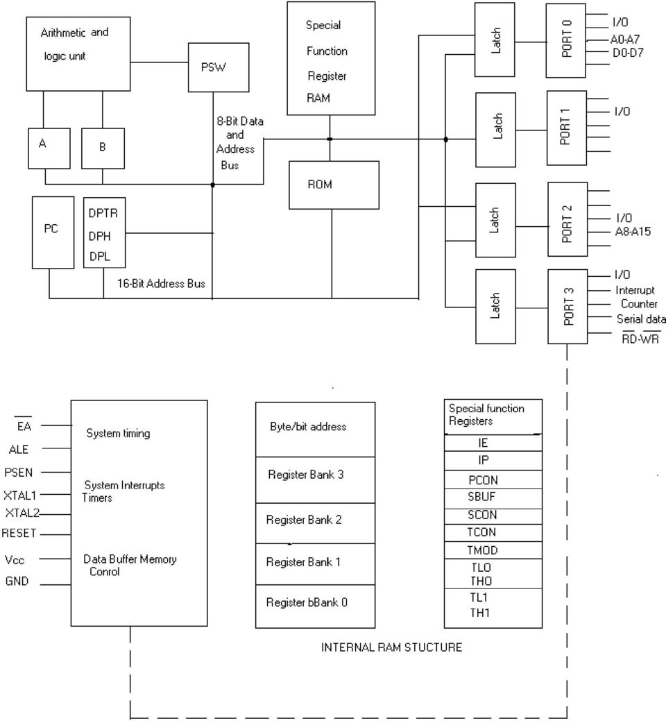
5 A BRIEF INTRODUCTION TO 8051 MICROCONTROLLER: When we have to learn about a new computer we have to familiarize about the machine capability we are using, and we can do it by studying the internal hardware design (devices architecture), and also to know about the size, number and the size of the registers. A microcontroller is a single chip that contains the processor (the CPU), non-volatile memory for the program (ROM or flash), volatile memory for input and output (RAM), a clock and an I/O control unit. Also called a "computer on a chip," billions of microcontroller units (MCUs) are embedded each year in a myriad of products from toys to appliances to automobiles. For example, a single vehicle can use 70 or more microcontrollers. The following picture describes a general block diagram of microcontroller. AT89S52: The AT89S52 is a low-power, high-performance CMOS 8-bit microcontroller with 8K bytes of in-system programmable Flash memory. The device is manufactured using
 are embedded each year in a myriad of products from toys to appliances to automobiles.")
6 Atmel s high-density nonvolatile memory technology and is compatible with the industry-standard 80C51 instruction set and pin out. The on-chip Flash allows the program memory to be reprogrammed in-system or by a conventional nonvolatile memory programmer. By combining a versatile 8-bit CPU with in-system programmable Flash on a monolithic chip, the Atmel AT89S52 is a powerful microcontroller, which provides a highly flexible and cost-effective solution to many, embedded control applications. The AT89S52 provides the following standard features: 8K bytes of Flash, 256 bytes of RAM, 32 I/O lines, Watchdog timer, two data pointers, three 16-bit timer/counters, a six-vector two-level interrupt architecture, a full duplex serial port, on-chip oscillator, and clock circuitry. In addition, the AT89S52 is designed with static logic for operation down to zero frequency and supports two software selectable power saving modes. The Idle Mode stops the CPU while allowing the RAM, timer/counters, serial port, and interrupt system to continue functioning. The Power-down mode saves the RAM con-tents but freezes the oscillator, disabling all other chip functions until the next interrupt.

7 The hardware is driven by a set of program instructions, or software. Once familiar with hardware and software, the user can then apply the microcontroller to the problems easily.

8 The pin diagram of the 8051 shows all of the input/output pins unique to microcontrollers: The following are some of the capabilities of 8051 microcontroller. 1. Internal ROM and RAM 2. I/O ports with programmable pins 3. Timers and counters 4. Serial data communication

9 The 8051 architecture consists of these specific features: 16 bit PC &data pointer (DPTR) 8 bit program status word (PSW) 8 bit stack pointer (SP) Internal ROM 4k Internal RAM of 128 bytes. 4 register banks, each containing 8 registers 80 bits of general purpose data memory 32 input/output pins arranged as four 8 bit ports: P0-P3 Two 16 bit timer/counters: T0-T1 Two external and three internal interrupt sources Oscillator and clock circuits.

10
11
12

13
14 BLOCK DIAGRAM POWER SUPPLY MOBILE (USER) GSM MODEM 8 9 S 5 2 LIQUID CRYSTAL DISPLAY RFID READER MODULE

15 CIRCUIT DIAGRAM

16 COMPONENT LIST Name Capacity Quantity 2 Pin Connector Screw 1 2 Pin Connector Male 1 Diode IN Regulator Regulator Capacitor 1000µf 1 Capacitor 10µf 1 Ceramic Capacitor 22pf 2 Crystal m 1 hz Push Button 1 40 Pin Base AT89S52 1 LED 2 LCD Base 16 Pin 1 LCD 16*2 1 Resistance 220Ω 2 Resistance 1k 1 Resistance 10k 1 RFID READER 1 GSM MODEM 1

17 HARDWARE DESCRIPTION: 1. POWER SUPPLY: Power supply is a reference to a source of electrical power. A device or system that supplies electrical or other types of energy to an output load or group of loads is called a power supply unit or PSU. The term is most commonly applied to electrical energy supplies, less often to mechanical ones, and rarely to others. Here in our application we need a 5v DC power supply for all electronics involved in the project. This requires step down transformer, rectifier, voltage regulator, and filter circuit for generation of 5v DC power. Here a brief description of all the components is given as follows: TRANSFORMER: transformer is a device that transfers electrical energy from one circuit to another through inductively coupled conductors the transformer's coils or "windings". Except for air-core transformers, the conductors are commonly wound around a single iron-rich core, or around separate but magnetically-

18 coupled cores. A varying current in the first or "primary" winding creates a varying magnetic field in the core (or cores) of the transformer. This varying magnetic field induces a varying electromotive force (EMF) or "voltage" in the "secondary" winding. This effect is called mutual induction. If a load is connected to the secondary circuit, electric charge will flow in the secondary winding of the transformer and transfer energy from the primary circuit to the load connected in the secondary circuit. The secondary induced voltage V S, of an ideal transformer, is scaled from the primary V P by a factor equal to the ratio of the number of turns of wire in their respective windings:

19 By appropriate selection of the numbers of turns, a transformer thus allows an alternating voltage to be stepped up by making N S more than N P or stepped down, by making it BASIC PARTS OF A TRANSFORMER In its most basic form a transformer consists of: A primary coil or winding. A secondary coil or winding. A core that supports the coils or windings. Refer to the transformer circuit in figure as you read the following explanation: The primary winding is connected to a 60-hertz ac voltage source. The magnetic field (flux) builds up (expands) and collapses (contracts) about the primary winding. The expanding and contracting magnetic field around the primary winding cuts the secondary winding and induces an alternating voltage into the winding. This voltage causes alternating current to flow through the load. The voltage may be stepped up or down depending on the design of the primary and secondary windings.
 builds up (expands) and collapses (contracts) about the primary winding.")
20 THE COMPONENTS OF A TRANSFORMER Two coils of wire (called windings) are wound on some type of core material. In some cases the coils of wire are wound on a cylindrical or rectangular cardboard form. In effect, the core material is air and the transformer is called an AIR-CORE TRANSFORMER. Transformers used at low frequencies, such as 60 hertz and 400 hertz, require a core of low-reluctance magnetic material, usually iron. This type of transformer is called an IRON-CORE TRANSFORMER. Most power transformers are of the iron-core type. The principle parts of a transformer and their functions are: The CORE, which provides a path for the magnetic lines of flux.

21 The PRIMARY WINDING, which receives energy from the ac source. The SECONDARY WINDING, which receives energy from the primary winding and delivers it to the load. The ENCLOSURE, which protects the above components from dirt, moisture, and mechanical damage. BRIDGE RECTIFIER A bridge rectifier makes use of four diodes in a bridge arrangement to achieve full-wave rectification. This is a widely used configuration, both with individual diodes wired as shown and with single component bridges where the diode bridge is wired internally. Basic operation According to the conventional model of current flow originally established by Benjamin Franklin and still followed by most engineers today, current is assumed to flow through electrical conductors from the positive to the negative pole. In actuality, free electrons in a conductor nearly always flow from the
22 negative to the positive pole. In the vast majority of applications, however, the actual direction of current flow is irrelevant. Therefore, in the discussion below the conventional model is retained. In the diagrams below, when the input connected to the left corner of the diamond is positive,, and the input connected to the right corner is negative,, current flows from the upper supply terminal to the right along the red (positive) path to the output, and returns to the lower supply terminal via the blue (negative) path. When the input connected to the left corner is negative, and the input connected to the right corner is positive,, current flows from the lower supply terminal to the right along the red path to the output, and returns to the upper supply terminal via the blue path.
23 In each case, the upper right output remains positive and lower right output negative. Since this is true whether the input is AC or DC, this circuit not only produces a DC output from an AC input, it can also provide what is sometimes called "reverse polarity protection". That is, it permits normal functioning of DC-powered equipment when batteries have been installed backwards, or when the leads (wires) from a DC power source have been reversed, and protects the equipment from potential damage caused by reverse polarity. Prior to availability of integrated electronics, such a bridge rectifier was always constructed from discrete components. Since about 1950, a single four-terminal component containing the four diodes connected in the bridge configuration became a
24 standard commercial component and is now available with various voltage and current ratings. OUTPUT SMOOTHING For many applications, especially with single phase AC where the full-wave bridge serves to convert an AC input into a DC output, the addition of a capacitor may be desired because the bridge alone supplies an output of fixed polarity but continuously varying or "pulsating" magnitude (see diagram above). The function of this capacitor, known as a reservoir capacitor (or smoothing capacitor) is to lessen the variation in (or 'smooth') the rectified AC output voltage waveform from the bridge. One explanation of 'smoothing' is that the capacitor provides a low impedance path to the AC component of the output, reducing the
25 AC voltage across, and AC current through, the resistive load. In less technical terms, any drop in the output voltage and current of the bridge tends to be canceled by loss of charge in the capacitor. This charge flows out as additional current through the load. Thus the change of load current and voltage is reduced relative to what would occur without the capacitor. Increases of voltage correspondingly store excess charge in the capacitor, thus moderating the change in output voltage / current. The simplified circuit shown has a well-deserved reputation for being dangerous, because, in some applications, the capacitor can retain a lethal charge after the AC power source is removed. If supplying a dangerous voltage, a practical circuit should include a reliable way to safely discharge the capacitor. If the normal load cannot be guaranteed to perform this function, perhaps because it can be disconnected, the circuit should include a bleeder resistor connected as close as practical across the capacitor. This resistor should consume a current large enough to discharge the capacitor in a reasonable time, but small enough to minimize unnecessary power waste.
26 Because a bleeder sets a minimum current drain, the regulation of the circuit, defined as percentage voltage change from minimum to maximum load, is improved. However in many cases the improvement is of insignificant magnitude. The capacitor and the load resistance have a typical time constant τ = RC where C and R are the capacitance and load resistance respectively. As long as the load resistor is large enough so that this time constant is much longer than the time of one ripple cycle, the above configuration will produce a smoothed DC voltage across the load. In some designs, a series resistor at the load side of the capacitor is added. The smoothing can then be improved by adding additional stages of capacitor resistor pairs, often done only for sub-supplies to critical high-gain circuits that tend to be sensitive to supply voltage noise. The idealized waveforms shown above are seen for both voltage and current when the load on the bridge is resistive. When the load includes a smoothing capacitor, both the voltage and the current waveforms will be greatly changed. While the voltage is smoothed, as described above, current will flow through the
27 bridge only during the time when the input voltage is greater than the capacitor voltage. For example, if the load draws an average current of n Amps, and the diodes conduct for 10% of the time, the average diode current during conduction must be 10n Amps. This non-sinusoidal current leads to harmonic distortion and a poor power factor in the AC supply. In a practical circuit, when a capacitor is directly connected to the output of a bridge, the bridge diodes must be sized to withstand the current surge that occurs when the power is turned on at the peak of the AC voltage and the capacitor is fully discharged. Sometimes a small series resistor is included before the capacitor to limit this current, though in most applications the power supply transformer's resistance is already sufficient. Output can also be smoothed using a choke and second capacitor. The choke tends to keep the current (rather than the voltage) more constant. Due to the relatively high cost of an effective choke compared to a resistor and capacitor this is not employed in modern equipment. Some early console radios created the speaker's constant field with the current from the high voltage ("B +") power supply,
28 which was then routed to the consuming circuits, (permanent magnets were then too weak for good performance) to create the speaker's constant magnetic field. The speaker field coil thus performed 2 jobs in one: it acted as a choke, filtering the power supply, and it produced the magnetic field to operate the speaker. REGULATOR IC (78XX) It is a three pin IC used as a voltage regulator. It converts unregulated DC current into regulated DC current. Normally we get fixed output by connecting the voltage regulator at the output of the filtered DC (see in above diagram). It can also be used in circuits to get a low DC voltage from a high DC voltage (for example we use 7805 to get 5V from 12V).
29 There are two types of voltage regulators 1. fixed voltage regulators (78xx, 79xx) 2. variable voltage regulators(lm317) In fixed voltage regulators there is another classification 1. +ve voltage regulators 2. -ve voltage regulators POSITIVE VOLTAGE REGULATORS This include 78xx voltage regulators. The most commonly used ones are 7805 and gives fixed 5V DC voltage if input voltage is in (7.5V, 20V). The Capacitor Filter The simple capacitor filter is the most basic type of power supply filter. The application of the simple capacitor filter is very limited. It is sometimes used on extremely high-voltage, low-current power supplies for cathode-ray and similar electron tubes, which require very little load current from the supply. The capacitor filter is also used where the power-supply ripple frequency is not critical; this frequency can be relatively high. The capacitor (C1) shown in figure 4-15 is a simple filter connected across the output of the rectifier in parallel with the load.
30 Full-wave rectifier with a capacitor filter. When this filter is used, the RC charge time of the filter capacitor (C1) must be short and the RC discharge time must be long to eliminate ripple action. In other words, the capacitor must charge up fast, preferably with no discharge at all. Better filtering also results when the input frequency is high; therefore, the full-wave rectifier output is easier to filter than that of the half-wave rectifier because of its higher frequency. For you to have a better understanding of the effect that filtering has on E avg, a comparison of a rectifier circuit with a filter and one without a filter is illustrated in views A and B of figure The output waveforms in figure 4-16 represent the unfiltered and filtered outputs of the half-wave rectifier circuit. Current pulses flow through the load resistance (R L ) each time a diode conducts. The dashed line indicates the average value of output voltage. For the half-wave rectifier, E avg is less than half (or
31 approximately 0.318) of the peak output voltage. This value is still much less than that of the applied voltage. With no capacitor connected across the output of the rectifier circuit, the waveform in view A has a large pulsating component (ripple) compared with the average or dc component. When a capacitor is connected across the output (view B), the average value of output voltage (E avg ) is increased due to the filtering action of capacitor C1. UNFILTERED FILTERED Half-wave rectifier with and without filtering.
32 The value of the capacitor is fairly large (several microfarads), thus it presents a relatively low reactance to the pulsating current and it stores a substantial charge. The rate of charge for the capacitor is limited only by the resistance of the conducting diode, which is relatively low. Therefore, the RC charge time of the circuit is relatively short. As a result, when the pulsating voltage is first applied to the circuit, the capacitor charges rapidly and almost reaches the peak value of the rectified voltage within the first few cycles. The capacitor attempts to charge to the peak value of the rectified voltage anytime a diode is conducting, and tends to retain its charge when the rectifier output falls to zero. (The capacitor cannot discharge immediately.) The capacitor slowly
33 discharges through the load resistance (R L ) during the time the rectifier is non-conducting. The rate of discharge of the capacitor is determined by the value of capacitance and the value of the load resistance. If the capacitance and load-resistance values are large, the RC discharge time for the circuit is relatively long. A comparison of the waveforms shown in figure 4-16 (view A and view B) illustrates that the addition of C1 to the circuit results in an increase in the average of the output voltage (E avg ) and a reduction in the amplitude of the ripple component (E r ) which is normally present across the load resistance. Now, let's consider a complete cycle of operation using a halfwave rectifier, a capacitive filter (C1), and a load resistor (R L ). As shown in view A of figure 4-17, the capacitive filter (C1) is assumed to be large enough to ensure a small reactance to the pulsating rectified current. The resistance of R L is assumed to be much greater than the reactance of C1 at the input frequency. When the circuit is energized, the diode conducts on the positive half cycle and current flows through the circuit, allowing C1 to charge. C1 will charge to approximately the peak value of the
34 input voltage. (The charge is less than the peak value because of the voltage drop across the diode (D1)). In view A of the figure, the charge on C1 is indicated by the heavy solid line on the waveform. As illustrated in view B, the diode cannot conduct on the negative half cycle because the anode of D1 is negative with respect to the cathode. During this interval, C1 discharges through the load resistor (R L ). The discharge of C1 produces the downward slope as indicated by the solid line on the waveform in view B. In contrast to the abrupt fall of the applied ac voltage from peak value to zero, the voltage across C1 (and thus across R L ) during the discharge period gradually decreases until the time of the next half cycle of rectifier operation. Keep in mind that for good filtering, the filter capacitor should charge up as fast as possible and discharge as little as possible. Figure 4-17A. - Capacitor filter circuit (positive and negative half cycles). POSITIVE HALF-CYCLE
35 Figure 4-17B. - Capacitor filter circuit (positive and negative half cycles). NEGATIVE HALF-CYCLE Since practical values of C1 and R L ensure a more or less gradual decrease of the discharge voltage, a substantial charge remains on the capacitor at the time of the next half cycle of operation. As a result, no current can flow through the diode until the rising ac input voltage at the anode of the diode exceeds
36 the voltage on the charge remaining on C1. The charge on C1 is the cathode potential of the diode. When the potential on the anode exceeds the potential on the cathode (the charge on C1), the diode again conducts, and C1 begins to charge to approximately the peak value of the applied voltage. After the capacitor has charged to its peak value, the diode will cut off and the capacitor will start to discharge. Since the fall of the ac input voltage on the anode is considerably more rapid than the decrease on the capacitor voltage, the cathode quickly become more positive than the anode, and the diode ceases to conduct. Operation of the simple capacitor filter using a full-wave rectifier is basically the same as that discussed for the half-wave rectifier. Referring to figure 4-18, you should notice that because one of the diodes is always conducting on. either alternation, the filter capacitor charges and discharges during each half cycle. (Note that each diode conducts only for that portion of time when the peak secondary voltage is greater than the charge across the capacitor.) Figure Full-wave rectifier (with capacitor filter).
37 Another thing to keep in mind is that the ripple component (E r) of the output voltage is an ac voltage and the average output voltage (E avg ) is the dc component of the output. Since the filter capacitor offers a relatively low impedance to ac, the majority of the ac component flows through the filter capacitor. The ac component is therefore bypassed (shunted) around the load resistance, and the entire dc component (or E avg ) flows through the load resistance. This statement can be clarified by using the formula for X C in a half-wave and full-wave rectifier. First, you must establish some values for the circuit.
38 As you can see from the calculations, by doubling the frequency of the rectifier, you reduce the impedance of the capacitor by one-half. This allows the ac component to pass through the
39 capacitor more easily. As a result, a full-wave rectifier output is much easier to filter than that of a half-wave rectifier. Remember, the smaller the X C of the filter capacitor with respect to the load resistance, the better the filtering action. Since the largest possible capacitor will provide the best filtering. Remember, also, that the load resistance is an important consideration. If load resistance is made small, the load current increases, and the average value of output voltage (E avg ) decreases. The RC discharge time constant is a direct function of the value of the load resistance; therefore, the rate of capacitor voltage discharge is a direct function of the current through the load. The greater the load current, the more rapid the discharge of the capacitor, and the lower the average value of output voltage. For this reason, the simple capacitive filter is seldom used with rectifier circuits that must supply a relatively large load current. Using the simple capacitive filter in conjunction with a full-wave or bridge rectifier provides improved filtering
40 because the increased ripple frequency decreases the capacitive reactance of the filter capacitor. CIRCUIT DIAGRAM OF POWER SUPPLY DIODE The diode is a p-n junction device. Diode is the component used to control the flow of the current in any one direction. The diode widely works in forward bias. Diode When the current flows from the P to N direction. Then it is in forward bias. The Zener diode is used in reverse bias function i.e. N to P direction. Visually the identification of the diode`s terminal can be done by identifying he silver/black line.
41 The silver/black line is the negative terminal (cathode) and the other terminal is the positive terminal (cathode). APPLICATION Diodes: Rectification, free-wheeling, etc Zener diode: Voltage control, regulator etc. Tunnel diode: Control the current flow, snobbier circuit, etc RESISTORS The flow of charge through any material encounters an opposing force similar in many respects to mechanical friction.this opposing force is called resistance of the material.in some electric circuit resistance is deliberately introduced in form of resistor. Resistor used fall in three categories, only two of which are color coded which are metal film and carbon film resistor.the third category is the wire wound type,where value are generally printed on the vitreous paint finish of the component. Resistors are in ohms and are represented in Greek letter omega, looks as an upturned horseshoe. Most electronic circuit require resistors to make them work properly and it is obliviously important to find out something about the different types of resistors available. Resistance is measured in ohms, the
42 symbol for ohm is an omega ohm. 1 ohm is quite small for electronics so resistances are often given in kohm and Mohm. Resistors used in electronics can have resistances as low as 0.1 ohm or as high as 10 Mohm. FUNCTION Resistor restrict the flow of electric current, for example a resistor is placed in series with a light-emitting diode(led) to limit the current passing through the LED. TYPES OF RESISTORS FIXED VALUE RESISTORS It includes two types of resistors as carbon film and metal film.these two types are explained under CARBON FILM RESISTORS During manufacture, at in film of carbon is deposited onto a small ceramic rod. The resistive coating is spiraled away in an automatic machine until the resistance between there two ends of the rods is as close as possible to the correct value. Metal
43 leads and end caps are added, the resistors is covered with an insulating coating and finally painted with colored bands to indicate the resistor value Carbon Film Resistors Another example for a Carbon Ohms or 22 Kilo-Ohms also known as 22K at 5% tolerance: Band 1 = Red, 1st digit Band 2 = Red, 2nd digit Band 3 = Orange, 3rd digit, multiply with zeros, in this case 3 zero's Band 4 = Gold, Tolerance, 5% METAL FILM RESISTORS Metal film and metal oxides resistors are made in a similar way, but can be made more accurately to within ±2% or ±1% of their nominal vale there are some difference in performance between these resistor types, but none which affects their use in simple circuit. WIRE WOUND RESISTOR
44 A wire wound resistor is made of metal resistance wire, and because of this, they can be manufactured to precise values. Also, high wattage resistors can be made by using a thick wire material. Wire wound resistors cannot be used for high frequency circuits. Coils are used in high frequency circuit. Wire wound resistors in a ceramic case, strengthened with special cement. They have very high power rating, from 1 or 2 watts to dozens of watts. These resistors can become extremely hot when used for high power application, and this must be taken into account when designing the circuit. TESTING Resistors are checked with an ohm meter/millimeter. For a defective resistor the ohm-meter shows infinite high reading. CAPACITORS In a way, a capacitor is a little like a battery. Although they work in completely different ways, capacitors and batteries both store electrical energy. If you have read How Batteries Work, then you know that a battery has two terminals. Inside the battery, chemical reactions produce electrons on one terminal and absorb electrons at the other terminal.
45 BASIC Like a battery, a capacitor has two terminals. Inside the capacitor, the terminals connect to two metal plates separated by a dielectric. The dielectric can be air, paper, plastic or anything else that does not conduct electricity and keeps the plates from touching each other. You can easily make a capacitor from two pieces of aluminum foil and a piece of paper. It won't be a particularly good capacitor in terms of its storage capacity, but it will work. In an electronic circuit, a capacitor is shown like this: When you connect a capacitor to a battery, here s what happens: The plate on the capacitor that attaches to the negative terminal of the battery accepts electrons that the battery is producing. The plate on the capacitor that attaches to the positive terminal of the battery loses electrons to the battery.
46 TESTING To test the capacitors, either analog meters or specia l digital meters with the specified function are used. The nonelectrolyte capacitor can be tested by using the digital meter. Multi meter mode : Continuity Positive probe : One end Negative probe : Second end Display : `0`(beep sound occur) `OL` Result : Faulty OK LED LED falls within the family of P-N junction devices. The light emitting diode (LED) is a diode that will give off visible light when it is energized. In any forward biased P-N junction there is, with in the structure and primarily close to the junction, a recombination of hole and electrons. This recombination requires that the energy possessed by the unbound free electron
47 be transferred to another state. The process of giving off light by applying an electrical source is called electroluminescence. LED is a component used for indication. All the functions being carried out are displayed by led.the LED is diode which glows when the current is being flown through it in forward bias condition. The LEDs are available in the round shell and also in the flat shells. The positive leg is longer than negative leg.
48 RADIO FREQUENCY IDENTIFICATION (RFID) INTRODUCTION RFID is the use of an object (typically referred to as an RFID tag) applied to or incorporated into a product, animal, or person for the purpose of identification and tracking using radio waves. Some tags can be read from several meters away and beyond the line of sight of the reader. RFIDs are easy to conceal or incorporate in other items. For example, in 2009 researchers at Bristol University successfully glued RFID micro transponders to live ants in order to study their behavior. This trend towards increasingly miniaturized RFIDs is likely to continue as technology advances. However, the ability to read at distance is limited by the inverse-square law. RFID is becoming increasingly prevalent as the price of the technology decreases. Governments use RFID applications for traffic management, while automotive companies use various RFID tracking solutions for product management. Many of these solutions may work together in the future, though privacy
49 regulations prevent many initiatives from moving forward at the same pace that technology allows. COMPONENTS OF RFID SYSTEM An RFID system consists of RFID tags, a means of reading or interrogating the tags and a means of communicating the data to a host computer or information management system. The system will also include a facility for entering or programming data into tags, if it is not done at the source by the manufacturer. There may also be present antennas for communication between the tag and the reader. A typical RFID system is made up of three components: 1. Tags, 2. Readers 3. Host computer system. RFID TAGS
50 An RFID tag is a tiny radio device that is also referred to as a transponder, smart tag, smart label or radio barcode. The word transponder is derived from the words transmitter and responder. The tag responds to a transmitted or communicated request for the data it carries. The tag comprises a simple silicon microchip (typically less than half a millimeter in size) attached to a small flat aerial and mounted on a substrate. The transponder memory may comprise of read-only (ROM), random access (RAM), and non-volatile programmable memory for data storage depending on the type and sophistication of the device. The ROM-based memory is used to accommodate security data and the transponder operating system instructions. The RAM-based memory is used for temporary data storage during transponder interrogation and response. The non-volatile programmable memory (EEPROM) used to store the transponder data and needs to be non-volatile to ensure that the data is retained when the device is in its quiescent or powersaving sleep state. Data buffers are further components of memory used to temporarily hold the incoming data following demodulation and
51 outgoing data for modulation and interface with the transponder antenna. The interface circuitry provides the facility to direct and accommodate the interrogation field energy for powering purposes in passive transponders and triggering of the transponder response. The transponder antenna senses the interrogating field and serves as the means for transmitting the transponder r response for interrogation. TYPES OF RFID TAGS On the basis of the presence of battery, tags can be classified into Active tags Passive tags. RFID Tag Data Format Printed barcode labels generally conform to the Universal Product Code standard (UPC) of product identification. RFID
52 tags used to identify products in the supply chain serve the same purpose, so it s often expeditious to explain RFID tags simply as ʺelectronic barcodes.ʺ Both RFID tags and barcode labels digitally convey information about objects. Currently, ʺClass 1+ʺ RFID tags are available with a digital memory of 96 bits, each bit being either logic 1 or a logic 0. Because alphanumeric characters (i.e., A to Z and 0 9) each require 8 bits of memory, it s possible to store 12 characters in an RFID tag (which isn t saying much). On the other hand those 96 bits represent a possible 79,228,162,514,264,300,000,000,000,000 (that s over 79.2 trillion) unique numerical identities. Or you could split the 96 bits into fields that each represents some characteristic of the object, creating a sort of family tree of objects. There are two basic tag data architectures. One is to include all information about a product (e.g., its size, date of manufactures, the quality inspector s name) on the tag itself. This has the advantage of decentralizing the data, but has a drawback in that the increased memory requirements on the tag increase its complexity and cost. The other way is for the tag to serve as a license plate for the object, which can be associated
53 with a database of its characteristics located in a centralized database. In 2000, Sarma, Brock, and Ashton of MITʹs Auto ID Project foresaw a world where all physical objects act as nodes in a networked physical world. 1 They propose an open architecture system that is independent of the specific tag technology affixed or built into the object being tracked. They proposed a common identification standard or Electronic Product Code (epc) standard. HEADER MANUFACTURER PRODUCT SERIAL CODE CODE NUMBER The header serves as a way of identifying the format of the sequence of bits that follow in the EPC. This makes system coding more flexible. That is a critical innovation because it allows for the use of various independent standards of identification to be understood by users of other formats. FREQUENCY RANGE OF RFID There are several versions of RFID that operate at different radio frequencies. The choice of frequency is dependent on the
54 business requirements and read environment it is not a technology where one size fits all applications. Three primary frequency bands are being used for RFID: Low Frequency (125/134KHz) Most commonly used for access control, animal tracking and asset tracking. High -Frequency (13.56 MHz) Used where medium data rate and read ranges up to about 1.5 meters are acceptable. This frequency also has the advantage of not being susceptible to interference from the presence of water or metals. Ultra High-Frequency (850 MHz to 950 MHz) offer the longest read ranges of up to approximately 3 meters and high reading speeds. READERS The reader, sometimes called an interrogator or scanner, sends and receives RF data to and from the tag via antennae. A reader may have multiple antennae that are responsible for sending and receiving radio waves.
55 The readers can be fixed or mobile, can read information stored on the tags and write information to them. This can be achieved without direct line of sight and in environments where traditional data collection could not operate. A major advantage is that information can be written to the tag multiple times so storing a history that travels with the article. The reader/interrogators can differ considerably in complexity depending on the type of tags being supported and functions to be fulfilled. The overall function is to provide the means of communicating with the tag and facilitating data transfer. Functions performed by readers include signal conditioning, parity error checking and correction. Once the signal from a transponder has been correctly received and decoded, algorithms can be applied to decide whether the signal is a repeat transmission and may then instruct the transponder to stop transmitting. This is known as Command Response Protocol and is used to circumvent the problem of reading multiple tags in a short span of time.
56 Using interrogators in this way is also referred to as Hands Down Polling. A more secure, but slower tag polling technique is called Hands Up Polling which involves the interrogator looking for tags with specific identities and interrogating them, in turn. A further approach uses multiple readers, multiplexed into one interrogator but results in cost increase. PRINCIPLE OF WORKING In the RFID system, the reader sends out a radio frequency wave to the tag and the tag broadcasts back its stored data to the reader. The system has two antennas, one for the tag and the other on the reader. The data collected from the tag can either be sent directly to a host computer through standard interfaces or it can be stored in a portable reader and later updated to the computer for data processing. The automatic reading and direct use of tag data is called automatic data capture. When the tag which is battery free, is to be read, the reader sends out a power pulse to the antenna lasting for about 50ms.The magnetic field generated is collected by the antenna in the transponder that is tuned to the same frequency. This
57 received energy is rectified and stored on a capacitor within the transponder. When the power pulse has finished, the transponder immediately transmits back its data, using the energy stored within its capacitor as its power source. The data is picked up by the receiving antenna and decoded by the reader unit. Once all the data has been transmitted, the storage capacitor is discharged resetting the transponder to make it ready for the next read cycle. The period between transmission pulses is called sync time and lasts between 20ms and 50ms depending on the system set up. TAG
58 Fig WORKING OF RFID SYSTEM The scanning antennas can be permanently affixed to a surface; handheld antennas are also available. They can take whatever shape you need; for example, you could build them into a door frame to accept data from persons or objects passing through. When an RFID tag passes through the field of the scanning antenna, it detects the activation signal from the antenna. That "wakes up" the RFID chip, and it transmits the information on its microchip to be picked up by the scanning antenna. ADVANTAGES RFID technology permits no line of sight reading.
59 Robustness and reliability under difficult environmental conditions. These tags can be read through water, snow, concrete, bricks, plastics, wood, and most non-metallic materials Available in a wide variety of physical forms, shapes, sizes and protective housings. RFID tags can be read at very high speeds. The tag need not be on the surface of the object (and is therefore not subject to wear). The read time is typically less than 100 milliseconds Large numbers of tags can be read at once rather than item by item. APPLICATIONS Principle areas of applications of RFID include: 1. Transportation 2. Manufacturing and processing. 3. Security. Texas Instruments Radio Frequency Identification (TI- RFid) Systems has introduced its new RFID tag for textile rental and dry cleaning applications. TI-RFid tags provide more
60 accurate identification and greater accountability as well as improved handling through each stage of cleaning and processing to final customer delivery. RFID system allows booksellers to gain such information as the range of books a shopper has browsed, the number of times a particular title was picked up, and even the length of time spent flipping through pages. The shelves can scan the contents of the shelves and, via computer, alert store employees when supplies are running low or when theft is detected.[4] RFID tags loaded with biometric information will be embedded in passports to ensure travelers comply with security regulations. RFID technology is also being used to improve luggage handling in airports. Certain specific applications of RFID include: 1. Fleet management. 2. Inventory and asset Management
61 GLOBAL SYSTEM FOR MOBILE COMMUNICATION (GSM) INTRODUCTION Definition GSM, which stands for Global System for Mobile communications, reigns (important) as the world s most widely used cell phone technology. Cell phones use a cell phone service
62 carrier s GSM network by searching for cell phone towers in the nearby area. Global system for mobile communication (GSM) is a globally accepted standard for digital cellular communication. GSM is the name of a standardization group established in 1982 to create a common European mobile telephone standard that would formulate specifications for a pan-european mobile cellular radio system operating at 900 MHz. It is estimated that many countries outside of Europe will join the GSM partnership. GSM ARCHITECTURE A GSM network consists of several functional entities whose functions and interfaces are defined. The GSM network can be divided into following broad parts. The Mobile Station (MS) The Base Station Subsystem (BSS) The Network Switching Subsystem (NSS) The Operation Support Subsystem (OSS) Following fig shows the simple architecture diagram of GSM Network.
63 The added components of the GSM architecture include the functions of the databases and messaging systems: Home Location Register (HLR) Visitor Location Register (VLR) Equipment Identity Register (EIR) Authentication Center (AuC) SMS Serving Center (SMS SC) Gateway MSC (GMSC) Chargeback Center (CBC) Transcoder and Adaptation Unit (TRAU) Following fig shows the diagram of GSM Network along with added elements. Fig:9.2.1 GSM Network along with added elements.
64 The MS and the BSS communicate across the Um interface, also known as the air interface or radio link. The BSS communicates with the Network Service Switching center across the A interface. GSM network areas In a GSM network, the following areas are defined: Cell: Cell is the basic service area, one BTS covers one cell. Each cell is given a Cell Global Identity (CGI), a number that uniquely identifies the cell. Location Area: A group of cells form a Location Area. This is the area that is paged when a subscriber gets an incoming call. Each Location Area is assigned a Location Area Identity (LAI). Each Location Area is served by one or more BSCs. MSC/VLR Service Area: The area covered by one MSC is called the MSC/VLR service area. PLMN: The area covered by one network operator is called PLMN. A PLMN can contain one or more MSCs.
65 The GSM networks parts are explained as follows 1) Mobile Station The mobile station (MS) consists of the physical equipment, such as the radio transceiver, display and digital signal processors, and a smart card called the Subscriber Identity Module (SIM). The SIM provides personal mobility, so that the user can have access to all subscribed services irrespective of both the location of the terminal and the use of a specific terminal. By inserting the SIM card into another GSM cellular phone, the user is able to receive calls at that phone, make calls from that phone, or receive other subscribed services. The mobile equipment is uniquely identified by the International Mobile Equipment Identity (IMEI). The SIM card contains the International Mobile Subscriber Identity (IMSI), identifying the subscriber, a secret key for authentication, and other user information. The IMEI and the IMSI are independent, thereby providing personal mobility. The SIM card may be protected against unauthorized use by a password or personal identity number. 2) Base Station Subsystem
66 The Base Station Subsystem is composed of two parts, the Base Transceiver Station (BTS) and the Base Station Controller (BSC). These communicate across the specified Abis interface, allowing (as in the rest of the system) operation between components made by different suppliers. The Base Transceiver Station houses the radio transceivers that define a cell and handles the radio link protocols with the Mobile Station. In a large urban area, there will potentially be a large number of BTSs deployed. The requirements for a BTS are ruggedness, reliability, portability, and minimum cost. The Base Station Controller manages the radio resources for one or more BTSs. It handles radio channel setup, frequency hopping, and handovers, as described below. The BSC is the connection between the mobile and the Mobile service Switching Center (MSC). The BSC also translates the 13 kbps voice channel used over the radio link to the standard 64 kbps channel used by the Public Switched Telephone Network or ISDN. 3) Network Subsystem
67 The central component of the Network Subsystem is the Mobile services Switching Center (MSC). It acts like a normal switching node of the PSTN or ISDN, and in addition provides all the functionality needed to handle a mobile subscriber, such as registration, authentication, location updating, handovers, and call routing to a roaming subscriber. These services are provided in conjunction with several functional entities, which together form the Network Subsystem. The MSC provides the connection to the public fixed network (PSTN or ISDN), and signaling between functional entities uses the ITUT Signaling System Number 7 (SS7), used in ISDN and widely used in current public networks. The Home Location Register (HLR) and Visitor Location Register (VLR), together with the MSC, provide the call routing and (possibly international) roaming capabilities of GSM. The HLR contains all the administrative information of each subscriber registered in the corresponding GSM network, along with the current location of the mobile. The current location of the mobile is in the form of a Mobile Station Roaming Number (MSRN) which is a regular ISDN number
68 used to route a call to the MSC where the mobile is currently located. There is logically one HLR per GSM network, although it may be implemented as a distributed database. The Visitor Location Register contains selected administrative information from the HLR, necessary for call control and provision of the subscribed services, for each mobile currently located in the geographical area controlled by the VLR. Although each functional entity can be implemented as an independent unit, most manufacturers of switching equipment implement one VLR together with one MSC, so that the geographical area controlled by the MSC corresponds to that controlled by the VLR, simplifying the signaling required. Note that the MSC contains no information about particular mobile stations - this information is stored in the location registers. The other two registers are used for authentication and security purposes. The Equipment Identity Register (EIR) is a database that contains a list of all valid mobile equipment on the network, where each mobile station is identified by its International Mobile Equipment Identity (IMEI). An IMEI is marked as invalid if it has been reported stolen or is not type
69 approved. The Authentication Center is a protected database that stores a copy of the secret key stored in each subscriber's SIM card, which is used for authentication and ciphering of the radio channel. GSM - The Base Station Subsystem (BSS) The BSS is composed of two parts: The Base Transceiver Station (BTS) The Base Station Controller (BSC) The BTS and the BSC communicate across the specified Abis interface, enabling operations between components that are made by different suppliers. The radio components of a BSS may consist of four to seven or nine cells. A BSS may have one or more base stations. The BSS uses the Abis interface between the BTS and the BSC. A separate highspeed line (T1 or E1) is then connected from the BSS to the Mobile MSC. The Base Transceiver Station (BTS)
70 The BTS houses the radio transceivers that define a cell and handles the radio link protocols with the MS. In a large urban area, a large number of BTSs may be deployed. Transcoding and rate adaptation Time and frequency synchronizing Voice through full- or half-rate services Decoding, decrypting, and equalizing received signals Random access detection Timing advances Uplink channel measurements The Base Station Controller (BSC) The BSC manages the radio resources for one or more BTSs. It handles radio channel setup, frequency hopping, and handovers. The BSC is the connection between the mobile and the MSC. The BSC also translates the 13 Kbps voice channel used over the radio link to the standard 64 Kbps channel used by the Public Switched Telephone Network (PSDN) or ISDN.
71 It assigns and releases frequencies and time slots for the MS. The BSC also handles intercell handover. It controls the power transmission of the BSS and MS in its area. The function of the BSC is to allocate the necessary time slots between the BTS and the MSC. It is a switching device that handles the radio resources. Additional functions include: Control of frequency hopping Performing traffic concentration to reduce the number of lines from the MSC Providing an interface to the Operations and Maintenance Center for the BSS Reallocation of frequencies among BTSs Time and frequency synchronization Power management Time-delay measurements of received signals from the MS The Network Switching Subsystem (NSS) The Network switching system (NSS), the main part of which is the Mobile Switching Center (MSC), performs the switching of calls between the mobile and other fixed or mobile
72 network users, as well as the management of mobile services such as authentication. The switching system includes the following functional elements. Home Location Register (HLR) The HLR is a database used for storage and management of subscriptions. The HLR is considered the most important database, as it stores permanent data about subscribers, including a subscriber's service profile, location information, and activity status. When an individual buys a subscription in the form of SIM then all the information about this subscription is registered in the HLR of that operator. Mobile Services Switching Center (MSC) The central component of the Network Subsystem is the MSC. The MSC performs the switching of calls between the mobile and other fixed or mobile network users, as well as the management of mobile services such as such as registration, authentication, location updating, handovers, and call routing to a roaming subscriber. It also performs such functions as toll
73 ticketing, network interfacing, common channel signaling, and others. Every MSC is identified by a unique ID. Visitor Location Register (VLR) The VLR is a database that contains temporary information about subscribers that is needed by the MSC in order to service visiting subscribers. The VLR is always integrated with the MSC. When a mobile station roams into a new MSC area, the VLR connected to that MSC will request data about the mobile station from the HLR. Later, if the mobile station makes a call, the VLR will have the information needed for call setup without having to interrogate the HLR each time. Authentication Center (AUC) The Authentication Center is a protected database that stores a copy of the secret key stored in each subscriber's SIM card, which is used for authentication and ciphering of the radio channel. The AUC protects network operators from different types of fraud found in today's cellular world. Equipment Identity Register (EIR)
74 The Equipment Identity Register (EIR) is a database that contains a list of all valid mobile equipment on the network, where its International Mobile Equipment Identity (IMEI) identifies each MS. An IMEI is marked as invalid if it has been reported stolen or is not type approved. THE OPERATION SUPPORT SUBSYSTEM (OSS) The operations and maintenance center (OMC) is connected to all equipment in the switching system and to the BSC. The implementation of OMC is called the operation and support system (OSS). Here are some of the OMC functions: Administration and commercial operation (subscription, end terminals, charging and statistics). Security Management. Network configuration, Operation and Performance Management. Maintenance Tasks.
75 The operation and Maintenance functions are based on the concepts of the Telecommunication Management Network (TMN) which is standardized in the ITU-T series M.30. The OSS is the functional entity from which the network operator monitors and controls the system. The purpose of OSS is to offer the customer cost-effective support for centralized, regional and local operational and maintenance activities that are required for a GSM network. An important function of OSS is to provide a network overview and support the maintenance activities of different operation and maintenance organizations. THE GSM SPECIFICATIONS Specifications for different Personal Communication Services (PCS) systems vary among the different PCS networks. The GSM specification is listed below with important characteristics. Modulation Modulation is a form of change process where we change the input information into a suitable format for the transmission
76 medium. We also changed the information by demodulating the signal at the receiving end. The GSM uses Gaussian Minimum Shift Keying (GMSK) modulation method. Access Methods Because radio spectrum is a limited resource shared by all users, a method must be devised to divide up the bandwidth among as many users as possible. GSM chose a combination of TDMA/FDMA as its method. The FDMA part involves the division by frequency of the total 25 MHz bandwidth into 124 carrier frequencies of 200 khz bandwidth. One or more carrier frequencies are then assigned to each BS. Each of these carrier frequencies is then divided in time, using a TDMA scheme, into eight time slots. One time slot is used for transmission by the mobile and one for reception. They are separated in time so that the mobile unit does not receive and transmit at the same time. Transmission Rate
77 The total symbol rate for GSM at 1 bit per symbol in GMSK produces K symbols/second. The gross transmission rate of the time slot is 22.8 Kbps. GSM is a digital system with an over-the-air bit rate of 270 kbps. Frequency Band The uplink frequency range specified for GSM is MHz (basic 900 MHz band only). The downlink frequency band MHz (basic 900 MHz band only). Channel Spacing This indicates separation between adjacent carrier frequencies. In GSM, this is 200 khz. Speech Coding GSM uses linear predictive coding (LPC). The purpose of LPC is to reduce the bit rate. The LPC provides parameters for a filter that mimics the vocal tract. The signal passes through
78 this filter, leaving behind a residual signal. Speech is encoded at 13 kbps. Duplex Distance The duplex distance is 80 MHz. Duplex distance is the distance between the uplink and downlink frequencies. A channel has two frequencies, 80 MHz apart. Misc Frame duration: ms Duplex Technique: Frequency Division Duplexing (FDD) access mode previously known as WCDMA. Speech channels per RF channel: 8. GSM - ADDRESSES AND IDENTIFIERS GSM distinguishes explicitly between user and equipment and deals with them separately. Besides phone numbers and subscriber and equipment identifiers, several other identifiers have been defined; they are needed for the management of subscriber mobility and for addressing of all the remaining network elements. The most important addresses and identifiers are presented in the following:
79 International Mobile Station Equipment Identity (IMEI) The international mobile station equipment identity (IMEI) uniquely identifies a mobile station internationally. It is a kind of serial number. The IMEI is allocated by the equipment manufacturer and registered by the network operator and registered by the network operator who stores it in the EIR. By means of IMEI one recognizes obsolete, stolen or nonfunctional equipment. International Mobile Subscriber Identity (IMSI) Each registered user is uniquely identified by its international mobile subscriber identity (IMSI). It is stored in the subscriber identity module (SIM) a mobile station can only be operated if a SIM with a valid IMSI is inserted into equipment with a valid IMEI. SECURITY AND ENCRYPTION
80 The security methods standardized for the GSM System make it the most secure cellular telecommunications standard currently available. Although the confidentiality of a call and anonymity of the GSM subscriber is only guaranteed on the radio channel, this is a major step in achieving end-to- end security. The subscriber's anonymity is ensured through the use of temporary identification numbers. The confidentiality of the communication itself on the radio link is performed by the application of encryption algorithms and frequency hopping which could only be realized using digital systems and signaling. Mobile Station Authentication The GSM network authenticates the identity of the subscriber through the use of a challenge-response mechanism. A 128-bit random number (RAND) is sent to the MS. The MS computes the 32-bit signed response (SRES) based on the encryption of the random number (RAND) with the authentication algorithm (A3) using the individual subscriber authentication key (Ki). Upon receiving the signed response
81 (SRES) from the subscriber, the GSM network repeats the calculation to verify the identity of the subscriber. The individual subscriber authentication key (Ki) is never transmitted over the radio channel. It is present in the subscriber's SIM, as well as the AUC, HLR, and VLR databases as previously described. If the received SRES agrees with the calculated value, the MS has been successfully authenticated and may continue. If the values do not match, the connection is terminated and an authentication failure indicated to the MS. The calculation of the signed response is processed within the SIM. This provides enhanced security, because the confidential subscriber information such as the IMSI or the individual subscriber authentication key (Ki) is never released from the SIM during the authentication process. Signaling and Data Confidentiality The SIM contains the ciphering key generating algorithm (A8) which is used to produce the 64-bit ciphering key (Kc). The ciphering key is computed by applying the same random number (RAND) used in the authentication process to
82 the ciphering key generating algorithm (A8) with the individual subscriber authentication key (Ki). As will be shown in later sections, the ciphering key (Kc) is used to encrypt and decrypt the data between the MS and BS. An additional level of security is provided by having the means to change the ciphering key, making the system more resistant to eavesdropping. The ciphering key may be changed at regular intervals as required by network design and security considerations. In a similar manner to the authentication process, the computation of the ciphering key (Kc) takes place internally within the SIM. Therefore sensitive information such as the individual subscriber authentication key (Ki) is never revealed by the SIM. Encrypted voice and data communications between the MS and the network is accomplished through use of the ciphering algorithm A5. Encrypted communication is initiated by a ciphering mode request command from the GSM network. Upon receipt of this command, the mobile station begins encryption and decryption of data using the ciphering algorithm (A5) and the ciphering key (Kc).
83 Subscriber Identity Confidentiality To ensure subscriber identity confidentiality, the Temporary Mobile Subscriber Identity (TMSI) is used. The TMSI is sent to the mobile station after the authentication and encryption procedures have taken place. The mobile station responds by confirming reception of the TMSI. The TMSI is valid in the location area in which it was issued. For communications outside the location area, the Location Area Identification (LAI) is necessary in addition to the TMSI. Telephony Service These services can be charged on per call basis. Only call initiator has to pay the charges and now a day, all the incoming charges are free. A customer can be charged based on different parameters like: International call or long distance call. Local call Call made during peak hours. Call made during night time
84 Discounted call during weekends. Call per minute or per second. Many more other criteria can be designed by a service provider to charge their customers. SMS Service Till the time this tutorial is written, most of the service providers are charging their customer's SMS services based on number of text messages sent from their mobile phone. There are other prime SMS services available where service providers are charging more than normal SMS charge. These services are being used in collaboration of Television Networks or Radio Networks to demand SMS from the audiences Most of time charges are paid by the SMS sender but for some services like stocks and share prices, mobile banking facilities and leisure booking services etc. recipient of the SMS has to pay for the service. GPRS Services
85 Using GPRS service we can browse Internet and can play games on the Internet, we can download movies or music etc. So a service provider will charge us based on the data uploaded as well as data downloaded on our mobile phone. These charges will be based on per Kilo Byte data downloaded/uploaded. Additional parameter could be a Quality of Service provided to us. If we want to watch a movie then a low quality may work because some data loss may be acceptable to us but if we are downloading a zip file then a single byte loss will corrupt our complete downloaded file. Advantages of GSM GSM is already used worldwide with over 450 million subscribers. International roaming permits subscribers to use one phone throughout Western Europe. CDMA will work in Asia, but not France, Germany, the U.K. and other popular European destinations. GSM is mature, having started in the mid-80s. This maturity means a more stable network with robust features. CDMA is still building its network.
86 LCD PIN DESCRIPTIONS Fig 1. Shows the pin diagram of a 14 pin LCD.
87 The LCD used here has 14 pins. The functions of each pin is given below: VCC, VSS, and VEE : While Vcc and Vss provide +5V and ground, respectively, VEE is used for controlling LCD contrast. RS, REGISTER SELECT:
88 There are two very important registers inside the LCD. The RS pin is used for their selection as follows.if RS = 0, then instruction command code register is selected, allowing the user to send the command such as clear display, cursor at home, etc. If RS = 1 the data register is selected, allowing the user to send data to be displayed on the LCD. R/W, READ/WRITE: R/W input allows the user to write information to the LCD or read information from it. R/W =1 when reading ; R/W = 0 when writing. E, ENABLE: The enable pin is used by the LCD to latch information presented to its data pins. When data is supplied to data pins, a high to low pulse must be applied to this pin in order for the LCD to latch in the data present at the data pins. This pulse must be a minimum of 450 ns wide. D0 D7:
89 The 8 bit data pins, D0 D7, are used to send information to the LCD or read the contents of the LCD's internal registers. To display letters and numbers, we send ASCII codes for the letters A- Z, a-z, and 0-9 to these pins while making RS = 1. There are also instruction command codes that can be send to the LCD to clear the display or force to cursor to the home position or blink the cursor. We also use RS=0 to check the busy flag bit to see if the LCD is ready to receive information. The busy flag is D7 and can be read when R/W=1.RS=0, as follows: if R/W=1 and RS=0.When D7=1 (busy flag=1), the LCD is busy taking care of internal operations and will not accept any new information. When D7 = 0, the LCD is ready to receive new information. PIN DESCRIPTION FOR LCD Pi Sym I/O Description n bol 1 Vss -- Ground 2 Vcc -- +5V power supply 3 VE -- Power supply to control contrast
90 E 4 RS I RS=0 for command register, RS=1 for data register 5 R/W I R/W+0 for write, R/W+1 for read 6 E I/O Enable 7 DB0 I/O The 8-bit data bus 8 DB1 I/O The 8-bit data bus 9 DB2 I/O The 8-bit data bus 10 DB3 I/O The 8-bit data bus 11 DB4 I/O The 8-bit data bus 12 DB5 I/O The 8-bit data bus 13 DB6 I/O The 8-bit data bus 14 DB7 I/O The 8-bit data bus LCD Command Codes Code (Hex) Command to LCD Instruction Register 1 Clear display screen 2 Return home
91 4 Decrement cursor(shift cursor to left) 6 Increment cursor(shift cursor to right) 5 Shift display left 7 Shift display left 8 Display off, cursor off A Display off, cursor on C Display on, cursor off E Display on F Display on, cursor blinking 10 Shift cursor position to left 14 Shift cursor position to right 18 Shift the entire display to the left 1C Shift the entire display to the right 80 Force cursor to beginning of first line C0 Force cursor to beginning of second line 38 2 lines and 5x7 matrix WORKING:
92 The interface used by LCD is a parallel bus, allowing simple and fast reading/writing of data to and from the LCD.. This waveform will write an ASCII Byte out to the LCD's screen. The ASCII code to be displayed is eight bits long and is sent to the LCD either four or eight bits at a time. If four bit mode is used, two "nibbles" of data (Sent high four bits and then low four bits with an "Enable" Clock pulse with each nibble) are sent to make up a full eight bit transfer. The "Enable" Clock is used to initiate the data transfer within the LCD.
93 Sending parallel data as either four or eight bits are the two primary modes of operation. While there are secondary considerations and modes, deciding how to send the data to the LCD is most critical decision to be made for an LCD interface application. Eight bit mode is best used when speed is required in an application and at least ten I/O pins are available. Four bit mode requires a minimum of six bits. To wire a microcontroller to an LCD in four bit mode, just the top four bits (DB4-7) are written to. The "RS" bit is used to select whether data or an instruction is being transferred between the microcontroller and the LCD. If the Bit is set, then the byte at the current LCD "Cursor" Position can be read or written. When the Bit is reset, either an instruction is being sent to the LCD or the execution status of the last instruction is read back (whether or not it has completed). Reading Data back is best used in applications which required data to be moved back and forth on the LCD (such as in applications which scroll data between lines).in our Project we
94 have permanently grounded R/W pin which means we are not retrieving any data from LCD. The LCD can be thought of as a "Teletype" display because in normal operation, after a character has been sent to the LCD, the internal "Cursor" is moved one character to the right. The "Clear Display" and "Return Cursor and LCD to Home Position" instructions are used to reset the Cursor's position to the top right character on the display. To move the Cursor, the "Move Cursor to Display" instruction is used. For this instruction, bit 7 of the instruction byte is set with the remaining seven bits used as the address of the character on the LCD the cursor is to move to. These seven bits provide 128 addresses, which matches the maximum number of LCD character addresses available.
95 Eight programmable characters are available and use codes 0x000 to 0x007. They are programmed by pointing the LCD's "Cursor" to the Character Generator RAM The last aspect of the LCD to discuss is how to specify a contrast voltage to the Display. I typically use a potentiometer wired as a voltage divider. This will provide an easily variable voltage between Ground and Vcc, which will be used to specify the contrast (or "darkness") of the characters on the LCD screen. You may find that different LCDs work differently with lower voltages providing darker characters in some and higher voltages do the same thing in others CIRCUIT DIAGRAM OF LCD INTERFACING
96 µvision The µ Vision IDE is, for most developers, the easiest way to create embedded system programs. This chapter describes commonly used µ Vision features and explains how to use them.
97 General Remarks and Concepts Before we start to describe how to use µvision, some general remarks, common to many screens1 and to the behavior of the development tool, are presented. In our continuous effort to deliver best-in-class development tools, supporting you in your daily work, µvision has been built to resemble the look-and-feel of widespread applications. This approach decreases your learning curve, such that you may start to work with µ Vision right away. Based on the concept of windows: µ Vision windows can be re-arranged, tiled, and attached to other screen areas or windows respectively It is possible to drag and drop windows, objects, and variables A Context Menu, invoked through the right mouse button, is provided for most objects. You can use keyboard shortcuts and define your own shortcuts. You can use the abundant features of a modern editor. Menu items and Toolbar buttons are greyed out when not available in the Current context. Graphical symbols are used to resemble options, to mark unsaved changes, or reveal objects not included into the project.
98 Status Bars display context-driven information.you can associate µvision to third-party tools
99 The Project Windows area is that part of the screen in which, by default, the Project Window, Functions Window, Books Window, and Registers Window are displayed. Within the Editor Windows area, you are able to change the source code, view performance and analysis information, and check the disassembly code. The Output Windows area provides information related to debugging, memory, symbols, call stack, local variables, commands, browse information, and find in files results.
100 If, for any reason, you do not see a particular window and have tried displaying/hiding it several times, please invoke the default layout of µvision through the Window Reset Current Layout Menu. Positioning Windows The µvision windows may be placed onto any area of the screen, even outside of the µvision frame, or to another physical screen. Click and hold the Title Bar1 of a window with the left mouse button Drag the window to the preferred area, or onto the preferred control, and release the mouse button Please note, source code files cannot be moved outside of the Editor Windows2.\ Invoke the Context Menu of the window s Title Bar to change the docking attribute of a window object. In some cases, you must perform this action before you can drag and drop the window.
101 µvision displays docking helper controls3, emphasizing the area where the window will be attached. The new docking area is represented by the section highlighted in blue. Snap the window to the Multiple Document Interface (MDI) or to a Windows area by moving the mouse over the preferred control. Keil software converts the C-codes into the Intel Hex code. A view of Keil uvision 3
102 8051 Burner Software A view of Keil uvision 3

103 PRO51 BURNER provides you with software burning tools for 8051 based Microcontrollers in there Flash memory. The 51 BURNER tools, you can burn AT89SXXXX series of ATMEL microcontrollers. PRO 51
104 PRO51 - Programmer for C51 family Features of PRO51 Flash Programmer for 89C1051, 89C2051, 89C4051, 89S51, 89S52, 89C51 and 89C52 micros. Operates on single 5V supply which can be taken from USB Port of PC. User friendly windows based Graphics User Interface. Interfaces with PC through COM1 or COM2 serial ports. System Requirements PC with at least one serial and one USB ports and at least 600x800 VGA resolution. If USB port is not available you need a regulated +5V supply. Windows operating system Package Contents PRO51 unit
105 Interface Cable between PC and PRO51 CD containing PROG51 software Getting Started 1. Install PROG51 programs using setup from the CD. This would normally create these programs in a program group INFONICS. You may like to create a separate folder like INFONICS on your disk where these programs will be installed. 2. Connect PRO51 to COM port and USB on your PC using the Y cable provided with PRO51. Follow instruction given in the following sections. PROG51 User Interface Prog51 is used for programming the 89C1051, 89C2051 and 89C4051 Microcontrollers. User interface includes: Load Hex/Binary file in Buffer Save Buffer as Binary File
106 Display / Specify Target Device to be Programmed. Com Port Selection. Identify Target Device with the device specified by you in the designated area. Read Microcontroller Program in Buffer Erase Microcontroller Program Memory Check if Target Device is Erased Program Buffer Contents in Target device Verify the Device contents with data in the buffer 3. Lock Target Device. Once the device is locked it can not be read or verified.
107 Procedure to Program a Chip 1. Connect the PRO51 to COM port and USB port on your PC. USB is used for +5V power supply only. You can use regulated 5V supply and connect it on pin 4 of the 9 Pin connector. 2. Start PROG51 from your program menu. 3. Select appropriate com port on your PC. 4. Insert desired device in the ZIF socket on PRO Pin devices like 89C2051 should be aligned with the bolltom
108 side, i.e., pin 10 on the 89C2051 should be inserted in Pin 20 of the socket. 5. Specify the device in the target device text box. 6. Click Identify button to check if the device inserted matches with the one you specified in the Target Device text box. 7. Load Hex or Binary file generated using compiler or assembler in the buffer. 8. Click on Erase button to erase the contents of the flash memory of the microcontroller. Erase process will automatically be followed by a blank check. 9. Click on Program button to write the buffer contents in to the program memory of the microcontroller. Program action will automatically be followed by a verify cycle. 10. If you wish click on Lock button to secure the device. 11. Remove the device from ZIF socket. Fig 1. Block Diagram of PRO51
109 Power Supply RST RXD TXD Programmer ZIF Socket Pin description of 9 PIN male connector on PRO51 Pin Name Description 1 NC Not connected 2 RXD Serial Port Receive Data. This pin should
110 be connected to TXD pin of COM port on PC. 3 TXD Serial Port Transmit Data. This pin should be connected to RXD pin of COM port on PC. 4 VCC +5V supply for the PRO51. It must be regulated supply. Cable supplied with the device draws power from the USB port of your PC. If you wish to use any other source of power the same should be connected to this pin. 5 GND Signal and power ground for serial port and 5V power supply. 6 RXDEN If this pin is left open or pulled up (>3V) then RXD signal received at PIN 2 above is sent to the CPU. If you wish to disable the RXD signal then this PIN should be pulled Ve. With the standard cable supplied by Infonics this pin is connected to the DSR signal of COM port.
111 Therefore, the DSR must high to enable the RXD. 7 NC Not connected 8 RESET A high (> 3V) on this pin will reset the PRO51. With the standard cable supplied by Infonics this pin is connected to the RTS signal of COM port. Therefore, the RTS must be kept low for proper operation of the PRO51. A high pulse on RTS can be used to reset the device. 9 NC Not connected CONSTRUCTION AND TESTING CONSTRUCTION In the process of realizing this project, the construction was initially carried out on a breadboard to allow for checking and to ascertain that it is functioning effectively. All irregularities were checked then tested and found to have a satisfactory output. The component were then removed and transferred to a Vero board strip and soldered into place and all discontinuous point were cut out to avoid short-circuiting.
112 PRECAUTIONS SOLDERING PRECAUTIONS The construction was carried out with care. The precautions taken during the soldering were: The tip of soldering iron was kept clean with the help of a file from time to time. The solder wire was of smaller thickness. Extra solder was not used in order to avoid a cause of short circuit in the conductive path. The overheating of components was avoided to prevent component damage as a result of excessive heat on the components due to the heat from the soldering iron. The leads of the components were kept clean before soldering, with the use of sand paper. COMPONENTS PRECAUTION: IR sensor used should be sensitive. Before using in the circuit it should be tested with a multi-meter.
113 I.C should not be heated much while soldering; too much heat can destroy the I.C. For safety and ease of replacement, the use of I.C socket is suggested. While placing the I.C pin no 1 should be made sure at right hole. Opposite polarity of battery can destroy I.C so please check the polarity before switching ON the circuit. One should use diode in series with switch for safety since diode allows flowing current in one direction only. Each component was soldered neatly and clean. We should use insulated wires. TESTING OF PROJECT With the knowledge of operation of the system was tested step by step to the transistor output and the load was connected across the collector terminal of the transistor. ASSEMBLING
114 The whole system was packed in a plastic casing and provision was made for the IR to sense light from the outside.
115 REFERENCES 8051 and embedded system by Mazidi and Mazidi All datasheets from About AT89s8252 from And
116
HBeonLabs. Contact us:
 HBeonLabs Off. No. 46, 1st Floor, Kadamba Complex Gamma-I, Greater Noida (India) - 201308 Contact us: +91-120-4298000 +91-9212314779 [email protected] [email protected] www. hbeonlabs.com RFID AND
Microtronics technologies Mobile: 99707 90092
 For more Project details visit: http://www.projectsof8051.com/rfid-based-attendance-management-system/ Code Project Title 1500 RFid Based Attendance System Synopsis for RFid Based Attendance System 1.
Mobile Communications
 October 21, 2009 Agenda Topic 2: Case Study: The GSM Network 1 GSM System General Architecture 2 GSM Access network. 3 Traffic Models for the Air interface 4 Models for the BSS design. 5 UMTS and the path
Global System for Mobile Communication (GSM)
") Global System for Mobile Communication (GSM) Definition Global system for mobile communication (GSM) is a globally accepted standard for digital cellular communication. GSM is the name of a standardization
Global System for Mobile Communication (GSM) Definition Global system for mobile communication (GSM) is a globally accepted standard for digital cellular communication. GSM is the name of a standardization
GSM Architecture Training Document
 Training Document TC Finland Nokia Networks Oy 1 (20) The information in this document is subject to change without notice and describes only the product defined in the introduction of this documentation.
Location-Aware and Safer Cards: Enhancing RFID Security and Privacy
 Location-Aware and Safer Cards: Enhancing RFID Security and Privacy 1 K.Anudeep, 2 Mrs. T.V.Anantha Lakshmi 1 Student, 2 Assistant Professor ECE Department, SRM University, Kattankulathur-603203 1 [email protected],
The GSM and GPRS network T-110.300/301
 The GSM and GPRS network T-110.300/301 History The successful analog 1:st generation mobile telephone systems proved that there is a market for mobile telephones ARP (AutoRadioPuhelin) in Finland NMT (Nordic
Power Supplies. 1.0 Power Supply Basics. www.learnabout-electronics.org. Module
 Module 1 www.learnabout-electronics.org Power Supplies 1.0 Power Supply Basics What you ll learn in Module 1 Section 1.0 Power Supply Basics. Basic functions of a power supply. Safety aspects of working
ECEN 1400, Introduction to Analog and Digital Electronics
 ECEN 1400, Introduction to Analog and Digital Electronics Lab 4: Power supply 1 INTRODUCTION This lab will span two lab periods. In this lab, you will create the power supply that transforms the AC wall
GSM - Global System for Mobile Communications
 GSM - Global System for Mobile Communications VLR BTS BSC GMSC PSTN MS HLR 1) Overview of GSM architecture 2) GSM channel structure 05-1 GSM - Global System for Mobile Communications VLR BTS BSC GMSC PSTN
Diode Applications. by Kenneth A. Kuhn Sept. 1, 2008. This note illustrates some common applications of diodes.
 by Kenneth A. Kuhn Sept. 1, 2008 This note illustrates some common applications of diodes. Power supply applications A common application for diodes is converting AC to DC. Although half-wave rectification
How To Understand The Power Of An Freddi Tag (Rfid) System
 System") Radio Frequency Identification Done by: Haitham Habli. Table of contents Definition of RFID. Do they need license? RFID vs other identification systems. Classification of RFID systems. Emerge of passive
Radio Frequency Identification Done by: Haitham Habli. Table of contents Definition of RFID. Do they need license? RFID vs other identification systems. Classification of RFID systems. Emerge of passive
8-Bit Flash Microcontroller for Smart Cards. AT89SCXXXXA Summary. Features. Description. Complete datasheet available under NDA
 Features Compatible with MCS-51 products On-chip Flash Program Memory Endurance: 1,000 Write/Erase Cycles On-chip EEPROM Data Memory Endurance: 100,000 Write/Erase Cycles 512 x 8-bit RAM ISO 7816 I/O Port
Ch 2.3.3 GSM PENN. Magda El Zarki - Tcom 510 - Spring 98
 Ch 2.3.3 GSM In the early 80 s the European community decided to work together to define a cellular system that would permit full roaming in all countries and give the network providers freedom to provide
2 System introduction
 2 System introduction Objectives After this chapter the student will: be able to describe the different nodes in a GSM network. be able to describe geographical subdivision of a GSM network. be able to
RFID BASED VEHICLE TRACKING SYSTEM
 RFID BASED VEHICLE TRACKING SYSTEM Operating a managed, busy parking lot can pose significant challenges, especially to a government organization that also owns some of the vehicles in the lot. The parking
How To Understand The Gsm And Mts Mobile Network Evolution
 Mobile Network Evolution Part 1 GSM and UMTS GSM Cell layout Architecture Call setup Mobility management Security GPRS Architecture Protocols QoS EDGE UMTS Architecture Integrated Communication Systems
1. Introduction: The Evolution of Mobile Telephone Systems
 IEC: The Global System for Mobile Communication Tutorial: Index Page 1 of 14 Global System for Mobile Communication (GSM) Tutorial Definition Global System for Mobile Communication (GSM) is a globally
The full wave rectifier consists of two diodes and a resister as shown in Figure
 The Full-Wave Rectifier The full wave rectifier consists of two diodes and a resister as shown in Figure The transformer has a centre-tapped secondary winding. This secondary winding has a lead attached
!!! "# $ % & & # ' (! ) * +, -!!. / " 0! 1 (!!! ' &! & & & ' ( 2 3 0-4 ' 3 ' Giuseppe Bianchi
 * +, -!!. / 0! 1 (!!! ' &! & & & ' ( 2 3 0-4 ' 3 ' Giuseppe Bianchi") !!! "# $ % & & # ' (! ) * +, -!!. / " 0! 1 (!!! ' &! & & & ' ( 2 3 0-4 ' 3 ' "#$!!% "&'! #&'!%! () *+,, 3 & 5 &,! #-!*! ' & '.! #%!* //!! & (0)/!&/, 6 5 /, "! First system: NMT-450 (Nordic Mobile Telephone)
!!! "# $ % & & # ' (! ) * +, -!!. / " 0! 1 (!!! ' &! & & & ' ( 2 3 0-4 ' 3 ' "#$!!% "&'! #&'!%! () *+,, 3 & 5 &,! #-!*! ' & '.! #%!* //!! & (0)/!&/, 6 5 /, "! First system: NMT-450 (Nordic Mobile Telephone)
Lecture overview. History of cellular systems (1G) GSM introduction. Basic architecture of GSM system. Basic radio transmission parameters of GSM
 GSM introduction. Basic architecture of GSM system. Basic radio transmission parameters of GSM") Lecture overview History of cellular systems (1G) GSM introduction Basic architecture of GSM system Basic radio transmission parameters of GSM Analogue cellular systems 70 s In the early 70 s radio frequencies
Lecture overview History of cellular systems (1G) GSM introduction Basic architecture of GSM system Basic radio transmission parameters of GSM Analogue cellular systems 70 s In the early 70 s radio frequencies
AC Direct Off-Line Power Supplies
 AC Direct Off-Line Power Supplies r Introduction Many DC power supplies found in electronic systems, including those in this Tech School, rectify the 120 volts available at an electric outlet. The initial
Study Guide for the Electronics Technician Pre-Employment Examination
 Bay Area Rapid Transit District Study Guide for the Electronics Technician Pre-Employment Examination INTRODUCTION The Bay Area Rapid Transit (BART) District makes extensive use of electronics technology
Lecture - 4 Diode Rectifier Circuits
 Basic Electronics (Module 1 Semiconductor Diodes) Dr. Chitralekha Mahanta Department of Electronics and Communication Engineering Indian Institute of Technology, Guwahati Lecture - 4 Diode Rectifier Circuits
Monitoring of Intravenous Drip Rate
 Monitoring of Intravenous Drip Rate Vidyadhar V. Kamble, Prem C. Pandey, Chandrashekar P. Gadgil, and Dinesh S. Choudhary Abstract A drip rate meter, for monitoring intravenous infusion, is developed using
DESIGN OF SMS ENABLED CAR SECURITY SYSTEM
 DESIGN OF SMS ENABLED CAR SECURITY SYSTEM K. A. Amusa Federal University of Agriculture, Abeokuta, O. O. Nuga Federal University of Agriculture, Abeokuta, A. A. Adetomi Federal University of Agriculture,
ANADOLU UNIVERSITY DEPARTMENT OF ELECTRICAL AND ELECTRONICS ENGINEERING
 ANADOLU UNIVERSITY DEPARTMENT OF ELECTRICAL AND ELECTRONICS ENGINEERING EEM 102 INTRODUCTION TO ELECTRICAL ENGINEERING EXPERIMENT 9: DIODES AND DC POWER SUPPLY OBJECTIVE: To observe how a diode functions
Global System for Mobile Communication Technology
 Global System for Mobile Communication Technology Mobile Device Investigations Program Technical Operations Division DHS - FLETC GSM Technology Global System for Mobile Communication or Groupe Special
Global System for Mobile Communications (GSM)
") Global System for Mobile Communications (GSM) Nguyen Thi Mai Trang LIP6/PHARE [email protected] UPMC/PUF - M2 Networks - PTEL 1 Outline Principles of cellular networks GSM architecture Security
Global System for Mobile Communications (GSM) Nguyen Thi Mai Trang LIP6/PHARE [email protected] UPMC/PUF - M2 Networks - PTEL 1 Outline Principles of cellular networks GSM architecture Security
RC NETWORKS SALES GUIDE
 SALES GUIDE INTRODUCTION TO Recent developments in electronic equipment have shown the following trends: Increasing demands for numerical control machines, robotics and technically advanced appliances
RFID Based Real Time Password Authentication System for ATM
 IJSRD - International Journal for Scientific Research & Development Vol. 3, Issue 04, 2015 ISSN (online): 2321-0613 RFID Based Real Time Password Authentication System for ATM Soniya B. Milmile 1 Prof.
CHAPTER 2B: DIODE AND APPLICATIONS. D.Wilcher
 CHAPTER 2B: DIODE AND APPLICATIONS D.Wilcher 1 CHAPTER 2B: OBJECTIVES Analyze the operation of 3 basic types of rectifiers Describe the operation of rectifier filters and IC regulators Analyze the operation
International Journal of Engineering Research & Management Technology
 International Journal of Engineering Research & Management Technology March- 2015 Volume 2, Issue-2 Radio Frequency Identification Security System Mr. Shailendra Kumar Assistant Professor Department of
DIODE CIRCUITS LABORATORY. Fig. 8.1a Fig 8.1b
 DIODE CIRCUITS LABORATORY A solid state diode consists of a junction of either dissimilar semiconductors (pn junction diode) or a metal and a semiconductor (Schottky barrier diode). Regardless of the type,
Introduction Ericsson Handheld Telephone 1341-B
 Ericsson Handheld Telephone 1341-B 2 Contents General 5 The Mobile Telephone Network 6 Base Station and Cell 7 Radio Channels 7 Radio Coverage 8 Transmission Control and Communication 9 Quality Control
Protected Cash Withdrawal in Atm Using Mobile Phone
 www.ijecs.in International Journal Of Engineering And Computer Science ISSN:2319-7242 Volume 2 Issue 4 April, 2013 Page No. 1346-1350 Protected Cash Withdrawal in Atm Using Mobile Phone M.R.Dineshkumar
2G/3G Mobile Communication Systems
 2G/3G Mobile Communication Systems Winter 2012/13 Integrated Communication Systems Group Ilmenau University of Technology Outline 2G Review: GSM Services Architecture Protocols Call setup Mobility management
Properties of electrical signals
 DC Voltage Component (Average voltage) Properties of electrical signals v(t) = V DC + v ac (t) V DC is the voltage value displayed on a DC voltmeter Triangular waveform DC component Half-wave rectifier
ANYTIME ANYPLACE-REMOTE MONITORING OF STUDENTS ATTENDANCE BASED ON RFID AND GSM NETWORK
 ANYTIME ANYPLACE-REMOTE MONITORING OF STUDENTS ATTENDANCE BASED ON RFID AND GSM NETWORK Mr.C.S.Karthikeyan 1 S.Murugeswari 2 Assistant professor, Dept. of ECE, Kamaraj College of Engineering and Technology,
GPS & GSM BASED REAL-TIME VEHICLE TRACKING SYSTEM.
 GPS & GSM BASED REAL-TIME VEHICLE TRACKING SYSTEM. Introduction: The Proposed design is cost-effective, reliable and has the function of accurate tracking. When large object or vehicles were spread out
Unit/Standard Number. High School Graduation Years 2010, 2011 and 2012
 1 Secondary Task List 100 SAFETY 101 Demonstrate an understanding of State and School safety regulations. 102 Practice safety techniques for electronics work. 103 Demonstrate an understanding of proper
Hello and welcome to this training module for the STM32L4 Liquid Crystal Display (LCD) controller. This controller can be used in a wide range of
 controller. This controller can be used in a wide range of") Hello and welcome to this training module for the STM32L4 Liquid Crystal Display (LCD) controller. This controller can be used in a wide range of applications such as home appliances, medical, automotive,
Hello and welcome to this training module for the STM32L4 Liquid Crystal Display (LCD) controller. This controller can be used in a wide range of applications such as home appliances, medical, automotive,
GSM System Architecture
 Intersystem Operation and Mobility Management David Tipper Associate Professor Graduate Program in Telecommunications and Networking University it of Pittsburgh Telcom 2700 Slides 6 http://www.tele.pitt.edu/tipper.html
BSNL TTA Question Paper-Instruments and Measurement Specialization 2007
 BSNL TTA Question Paper-Instruments and Measurement Specialization 2007 (1) Instrument is a device for determining (a) the magnitude of a quantity (b) the physics of a variable (c) either of the above
White Paper. Wonderware Mobile Solutions RFID Technology. What s Inside: Invensys is now
 Invensys is now White Paper Wonderware Mobile Solutions RFID Technology Author: Don Frieden, VP Mobile Solutions, Invensys What s Inside: 1. Radio Frequency Identification (RFID) 2. The Wonderware Tracking
Yrd. Doç. Dr. Aytaç Gören
 H2 - AC to DC Yrd. Doç. Dr. Aytaç Gören ELK 2018 - Contents W01 Basic Concepts in Electronics W02 AC to DC Conversion W03 Analysis of DC Circuits W04 Transistors and Applications (H-Bridge) W05 Op Amps
GLOLAB Universal Telephone Hold
 GLOLAB Universal Telephone Hold 1 UNIVERSAL HOLD CIRCUIT If you have touch tone telephone service, you can now put a call on hold from any phone in the house, even from cordless phones and phones without
AppNote 404 EM MICROELECTRONIC - MARIN SA. EM4095 Application Note RFID. Title: Product Family: TABLE OF CONTENT. Application Note 404
 EM MICROELECTRONIC - MARIN SA AppNote 0 Title: Product Family: Application Note 0 EM095 Application Note RFID Part Number: EM095 Keywords: RFID Transceiver, Reader Chip, EM095 Date: 5 September 00 TABLE
A+ Guide to Managing and Maintaining Your PC, 7e. Chapter 1 Introducing Hardware
 A+ Guide to Managing and Maintaining Your PC, 7e Chapter 1 Introducing Hardware Objectives Learn that a computer requires both hardware and software to work Learn about the many different hardware components
Inductors. AC Theory. Module 3
 Module 3 AC Theory What you ll learn in Module 3. Section 3.1 Electromagnetic Induction. Magnetic Fields around Conductors. The Solenoid. Section 3.2 Inductance & Back e.m.f. The Unit of Inductance. Factors
RADIUS. Brief brochure. Product Purpose
 Product Purpose The Product is designed for searching, intercepting, registering and analyzing of communication sessions as well as service information circulating in cellular GSM networks without encryption
Wireless Cellular Networks: 1G and 2G
 Wireless Cellular Networks: 1G and 2G Raj Jain Professor of Computer Science and Engineering Washington University in Saint Louis Saint Louis, MO 63130 Audio/Video recordings of this lecture are available
Microcontroller Based Low Cost Portable PC Mouse and Keyboard Tester
 Leonardo Journal of Sciences ISSN 1583-0233 Issue 20, January-June 2012 p. 31-36 Microcontroller Based Low Cost Portable PC Mouse and Keyboard Tester Ganesh Sunil NHIVEKAR *, and Ravidra Ramchandra MUDHOLKAR
Implementing a Digital Answering Machine with a High-Speed 8-Bit Microcontroller
 Implementing a Digital Answering Machine with a High-Speed 8-Bit Microcontroller Zafar Ullah Senior Application Engineer Scenix Semiconductor Inc. Leo Petropoulos Application Manager Invox TEchnology 1.0
Chapter 3. Diodes and Applications. Introduction [5], [6]
![Chapter 3. Diodes and Applications. Introduction [5], [6]](/thumbs/40/21801962.jpg "Chapter 3. Diodes and Applications. Introduction [5], [6]") Chapter 3 Diodes and Applications Introduction [5], [6] Diode is the most basic of semiconductor device. It should be noted that the term of diode refers to the basic p-n junction diode. All other diode
Chapter 3 Diodes and Applications Introduction [5], [6] Diode is the most basic of semiconductor device. It should be noted that the term of diode refers to the basic p-n junction diode. All other diode
Cellular Network Organization. Cellular Wireless Networks. Approaches to Cope with Increasing Capacity. Frequency Reuse
 Cellular Network Organization Cellular Wireless Networks Use multiple low-power transmitters (100 W or less) Areas divided into cells Each served by its own antenna Served by base station consisting of
Constructing a precision SWR meter and antenna analyzer. Mike Brink HNF, Design Technologist.
 Constructing a precision SWR meter and antenna analyzer. Mike Brink HNF, Design Technologist. Abstract. I have been asked to put together a detailed article on a SWR meter. In this article I will deal
Wireless Sensor Network for Electric Meter Handling
 Wireless Sensor Network for Electric Meter Handling Swapnil Magar 1, Prof.Deshpande L.M. 2 PG Student [E&TC], Dept. of ECE, College of Engineering, Osmanabad, Maharashtra, India 1 Assistant professor,
EMI and t Layout Fundamentals for Switched-Mode Circuits
 v sg (t) (t) DT s V pp = n - 1 2 V pp V g n V T s t EE core insulation primary return secondary return Supplementary notes on EMI and t Layout Fundamentals for Switched-Mode Circuits secondary primary
Vehicle Scrutinizing using GPS & GSM Technologies Implemented with Ardunio controller
 Vehicle Scrutinizing using GPS & GSM Technologies Implemented with Ardunio controller A.Kalaiarasi 1, Raviram.P 2, Prabakaran. P M 3, ShanthoshKumar.K 4, Dheeraj B P 5 Assistant Professor, Dept. of EEE,
Theory and Practice. IT-Security: GSM Location System Syslog XP 3.7. Mobile Communication. December 18, 2001. GSM Location System Syslog XP 3.
 Participant: Hack contacting... IT-Security: Theory and Practice Mobile Communication December 18, 2001 Uwe Jendricke [email protected] Lecture Homepage: http://www.informatik.uni-freiburg.de/~softech/teaching/ws01/itsec/
Global System for Mobile Communication (GSM)
") Global System for Mobile Communication (GSM) Li-Hsing Yen National University of Kaohsiung GSM System Architecture Um (ME/SIM) C E C PSTN, ISDN, PSPDN, CSPDN A-bis A F A-bis C B BTS BSS BSC HLR VLR EIR
Global System for Mobile Communication (GSM) Li-Hsing Yen National University of Kaohsiung GSM System Architecture Um (ME/SIM) C E C PSTN, ISDN, PSPDN, CSPDN A-bis A F A-bis C B BTS BSS BSC HLR VLR EIR
AVX EMI SOLUTIONS Ron Demcko, Fellow of AVX Corporation Chris Mello, Principal Engineer, AVX Corporation Brian Ward, Business Manager, AVX Corporation
 AVX EMI SOLUTIONS Ron Demcko, Fellow of AVX Corporation Chris Mello, Principal Engineer, AVX Corporation Brian Ward, Business Manager, AVX Corporation Abstract EMC compatibility is becoming a key design
Module 5. Broadcast Communication Networks. Version 2 CSE IIT, Kharagpur
 Module 5 Broadcast Communication Networks Lesson 9 Cellular Telephone Networks Specific Instructional Objectives At the end of this lesson, the student will be able to: Explain the operation of Cellular
Using ISO 15693 Compliant RFID Tags in an Inventory Control System
 Using ISO 15693 Compliant RFID Tags in an Inventory Control System University: Louisiana State University, Baton Rouge, Louisiana Course: Undergraduate Capstone Project Student Team Members: Joseph Gates,
Line Reactors and AC Drives
 Line Reactors and AC Drives Rockwell Automation Mequon Wisconsin Quite often, line and load reactors are installed on AC drives without a solid understanding of why or what the positive and negative consequences
DS1307ZN. 64 x 8 Serial Real-Time Clock
 DS137 64 x 8 Serial Real-Time Clock www.maxim-ic.com FEATURES Real-time clock (RTC) counts seconds, minutes, hours, date of the month, month, day of the week, and year with leap-year compensation valid
Mobile Communications Chapter 4: Wireless Telecommunication Systems slides by Jochen Schiller with modifications by Emmanuel Agu
 Mobile Communications Chapter 4: Wireless Telecommunication Systems slides by Jochen Schiller with modifications by Emmanuel Agu Market GSM Overview Services Sub-systems Components Prof. Dr.-Ing. Jochen
Automated Intelligent Power Saving System and Security System
 Advance in Electronic and Electric Engineering. ISSN 2231-1297, Volume 3, Number 9 (2013), pp. 1167-1176 Research India Publications http://www.ripublication.com/aeee.htm Automated Intelligent Power Saving
Design And Implementation Of Bank Locker Security System Based On Fingerprint Sensing Circuit And RFID Reader
 Design And Implementation Of Bank Locker Security System Based On Sensing Circuit And RFID Reader Khaing Mar Htwe, Zaw Min Min Htun, Hla Myo Tun Abstract: The main goal of this system is to design a locker
TX GSM SMS Auto-dial Alarm System. Installation and User Manual
 TX GSM SMS Auto-dial Alarm System Installation and User Manual Product Features: 1. 16 wireless zones, 3 wired zones alarm system, suitable for small to medium size offices and homes. 2. The system uses
REPORT ON CANDIDATES WORK IN THE CARIBBEAN ADVANCED PROFICIENCY EXAMINATION MAY/JUNE 2008 ELECTRICAL AND ELECTRONIC TECHNOLOGY (TRINIDAD AND TOBAGO)
") CARIBBEAN EXAMINATIONS COUNCIL REPORT ON CANDIDATES WORK IN THE CARIBBEAN ADVANCED PROFICIENCY EXAMINATION MAY/JUNE 2008 ELECTRICAL AND ELECTRONIC TECHNOLOGY (TRINIDAD AND TOBAGO) Copyright 2008 Caribbean
CARIBBEAN EXAMINATIONS COUNCIL REPORT ON CANDIDATES WORK IN THE CARIBBEAN ADVANCED PROFICIENCY EXAMINATION MAY/JUNE 2008 ELECTRICAL AND ELECTRONIC TECHNOLOGY (TRINIDAD AND TOBAGO) Copyright 2008 Caribbean
RF-Enabled Applications and Technology: Comparing and Contrasting RFID and RF-Enabled Smart Cards
 RF-Enabled Applications and Technology: Comparing and Contrasting RFID and RF-Enabled Smart Cards January 2007 Developed by: Smart Card Alliance Identity Council RF-Enabled Applications and Technology:
= V peak 2 = 0.707V peak
 BASIC ELECTRONICS - RECTIFICATION AND FILTERING PURPOSE Suppose that you wanted to build a simple DC electronic power supply, which operated off of an AC input (e.g., something you might plug into a standard
Business/Home GSM Alarm System. Installation and User Manual
 Business/Home GSM Alarm System Installation and User Manual Brief Introduction: GSM 900/1800/1900 bands, can be used in most parts of the world Full duplex communication with the host Monitor the scene
The D.C Power Supply
 The D.C Power Supply Voltage Step Down Electrical Isolation Converts Bipolar signal to Unipolar Half or Full wave Smoothes the voltage variation Still has some ripples Reduce ripples Stabilize the output
Display Message on Notice Board using GSM
 Advance in Electronic and Electric Engineering. ISSN 2231-1297, Volume 3, Number 7 (2013), pp. 827-832 Research India Publications http://www.ripublication.com/aeee.htm Display Message on Notice Board
Security & Chip Card ICs SLE 44R35S / Mifare
 Security & Chip Card ICs SLE 44R35S / Mifare Intelligent 1 Kbyte EEPROM with Interface for Contactless Transmission, Security Logic and Anticollision according to the MIFARE -System Short Product Info
RF CONTROLLED VEHICLE ROBOT WITH METAL DETECTOR
 RF CONTROLLED VEHICLE ROBOT WITH METAL DETECTOR PAGE NO. 1. ABSTRACT 10 2. INTRODUCTION TO EMBEDDED SYSTEMS 13 3. BLOCK DIAGRAM OF PROJECT 4. HARDWARE REQUIREMENTS 4.1 VOLTAGE REGULATOR 4.2 MICROCONTROLLER
Glolab Talking Phone Dial Monitor
 Introduction The detects the tones generated when numbers are dialed on your touch tone telephone and speaks the numbers that were dialed. This verifies that you dialed the correct number and is especially
Basic Concepts in RFID Technology
 Basic Concepts in RFID Technology By Richard Moscatiello Introduction This paper explains the basic concepts of RFID technology. The presentation is (hopefully) in an easy to understand format. Topics
Power Supplies. Overview. Measuring Electricity. Understanding Electricity. Two Types of Current. Powering the PC
 Overview Power Supplies Chapter 7 In this chapter, you will learn to Explain the basics of electricity Provide proper power and cooling to the PC Troubleshoot electrical problems Measuring Electricity
Wireless power meter monitoring with power theft detection and intimation system using GSM and Zigbee networks
 IOSR Journal of Electronics and Communication Engineering (IOSR-JECE) e-issn: 2278-2834,p- ISSN: 2278-8735.Volume 9, Issue 6, Ver. I (Nov - Dec. 2014), PP 04-08 Wireless power meter monitoring with power
An Example of Mobile Forensics
 An Example of Mobile Forensics Kelvin Hilton K319 kchilton@staffsacuk [email protected] www.soc.staffs.ac.uk/kch1 Objectives The sources of evidence The subscriber The mobile station The network
AUTOMATIC LPG BOOKING, LEAKAGE DETECTION AND A REAL TIME LPG MEASUREMENT MONITORING SYSTEM
 AUTOMATIC LPG BOOKING, LEAKAGE DETECTION AND A REAL TIME LPG MEASUREMENT MONITORING SYSTEM R.Padmapriya, E.Kamini, [email protected],[email protected], IV Year Electronics and Communication Engineering,
POCKET SCOPE 2. The idea 2. Design criteria 3
 POCKET SCOPE 2 The idea 2 Design criteria 3 Microcontroller requirements 3 The microcontroller must have speed. 3 The microcontroller must have RAM. 3 The microcontroller must have secure Flash. 3 The
MANUAL FOR RX700 LR and NR
 MANUAL FOR RX700 LR and NR 2013, November 11 Revision/ updates Date, updates, and person Revision 1.2 03-12-2013, By Patrick M Affected pages, ETC ALL Content Revision/ updates... 1 Preface... 2 Technical
Indian Journal of Advances in Computer & Information Engineering Volume.1 Number.1 January-June 2013, pp.1-5 @ Academic Research Journals.
 Cellular System Rajat Chugh, Parag Jasoria, Tushar Arora, Nitin Ginotra and Vivek Anand V Semester, Department of Computer Science and Engineering, Dronacharya College of Engineering, Khentawas, Farukhnagar,
Radio Frequency Identification (RFID) An Overview
 An Overview") Radio Frequency Identification (RFID) An Overview How RFID Is Changing the Business Environment Today Radio frequency identification (RFID) technology has been in use for several decades to track and identify
Radio Frequency Identification (RFID) An Overview How RFID Is Changing the Business Environment Today Radio frequency identification (RFID) technology has been in use for several decades to track and identify
LABORATORY 10 TIME AVERAGES, RMS VALUES AND THE BRIDGE RECTIFIER. Bridge Rectifier
 LABORATORY 10 TIME AVERAGES, RMS VALUES AND THE BRIDGE RECTIFIER Full-wave Rectification: Bridge Rectifier For many electronic circuits, DC supply voltages are required but only AC voltages are available.
How To Power A Power Control On An Ip40 (Ipl) With A Power Supply (Iplug) With An Ip20 Controller (Iphones) With Power Control (Power Control) With No Antenna) With The Ip20 (Power)
 With A Power Supply (Iplug) With An Ip20 Controller (Iphones) With Power Control (Power Control) With No Antenna) With The Ip20 (Power)") MODEL NUMBER: ISC910-1-0-GB-XX ISC911-5-0-GB-XX IXP20 CONTROLLER SPECIFICATIONS Working Environment Plastic Housing... Power ImproX IXP20 Controller INSTALLATION MANUAL Designed to work in an indoor (dry)
MODEL NUMBER: ISC910-1-0-GB-XX ISC911-5-0-GB-XX IXP20 CONTROLLER SPECIFICATIONS Working Environment Plastic Housing... Power ImproX IXP20 Controller INSTALLATION MANUAL Designed to work in an indoor (dry)
Module 11: Conducted Emissions
 Module 11: Conducted Emissions 11.1 Overview The term conducted emissions refers to the mechanism that enables electromagnetic energy to be created in an electronic device and coupled to its AC power cord.
GSM System. Global System for Mobile Communications
 GSM System Global System for Mobile Communications Introduced in 1991. Settings of standards under ETSI (European Telecommunication Standards Institute) Services - Telephone services - Data services -
Firmware version: 1.10 Issue: 7 AUTODIALER GD30.2. Instruction Manual
 Firmware version: 1.10 Issue: 7 AUTODIALER GD30.2 Instruction Manual Firmware version: 2.0.1 Issue: 0.6 Version of the GPRS transmitters configurator: 1.3.6.3 Date of issue: 07.03.2012 TABLE OF CONTENTS
The Heartbeat behind Portable Medical Devices: Ultra-Low-Power Mixed-Signal Microcontrollers
 The Heartbeat behind Portable Medical Devices: Ultra-Low-Power Mixed-Signal Microcontrollers The proliferation of sophisticated yet affordable personal medical devices is transforming the health care industry,
Efficient and reliable operation of LED lighting is dependent on the right choice of current-limiting resistor
 Efficient and reliable operation of LED lighting is dependent on the right choice of current-limiting resistor Phil Ebbert, VP of Engineering, Riedon Inc. Introduction Not all resistors are the same and
Chap-02, Hardware and Software. Hardware Model
 Philadelphia University School of Business Administration INFO-101 Information Systems Prof London Chap-02, Hardware and Software Hardware Components Central processing unit (CPU) Arithmetic/logic unit
Wireless Mobile Telephony
 Wireless Mobile Telephony The Ohio State University Columbus, OH 43210 [email protected] http://www.cis.ohio-state.edu/~durresi/ 1 Overview Why wireless mobile telephony? First Generation, Analog
a leap ahead in analog
 EMV Contactless Payment Systems based on AS3911 Overview and System Simulations Giuliano Manzi, PhD Mannheim, May 23 25, 2012 CST EUROPEAN USER CONFERENCE 2012 a leap ahead in analog OUTLINE AS3911 OVERVIEW