Maximum Availability Architecture. Oracle Best Practices For High Availability
|
|
|
- Adrian Jones
- 7 years ago
- Views:
Transcription
1 Configuring Maximum Availability Architecture for Beehive with F5 BIG-IP Global and Local Traffic Manager: Beehive High Availability Oracle Maximum Availability Architecture White Paper March 2010 Maximum Availability Architecture Oracle Best Practices For High Availability
2 Executive Summary... 4 Beehive Architecture Overview... 4 Client Tier... 6 Application Tier... 7 Data Tier... 8 Ancillary Tier... 8 Best Practices... 9 F Beehive F5 Configuration Guide for Beehive Using the Configuration Table Document Naming Conventions Configuring SSL Configuring IMAP (Port 5143) Configuring SMTP (Port 2225) Configuring Oracle Beehive Transport Protocol (Port 21401) Configuring Oracle Secure BTPS (Port 5224) Configuring XMPP Beehive Presence (Port 5222) Configuring FTP Service (Port 2121) Configuring Beehive HTTP and HTTPS (Port 7777) Configuring Beekeeper (Port 7779) F5 Monitor Configuration Summary F5 TCP Profile Configuration Summary... 58
3 F5 Persistence Profile Configuration Summary F5 Pool Configuration Summary F5 Virtual Server Configuration Summary Configure Beehive to Work with the F5 BIG-IP LTM Set the Virtual Server and Ports Set the HTTP Listening Port Set Beehive HTTP Server for SSL Termination Setup TLS Setup XMPP Set the Beekeeper Virtual Server Appendix A: Terminology for F5 BIG-IP Local Traffic Manager Pool Member Virtual Server Profile Rule Monitor Persistence Appendix B: Configuring BIG-IP for Beehive to Use SSL Offload Prerequisites and Configuration Notes Using SSL Certificates and Keys Importing Certificates and Keys Creating the Beehive Client SSL Profile... 73
4 Creating the Beekeeper Client SSL Profile Creating the Beehive Redirect irule Configuring Beehive for SSL Termination Appendix C: F5 BIG-IP Example Configuration File Appendix D: Beehive Host: Port and URL Summary References Oracle F5 References... 86
5 Executive Summary Oracle Maximum Availability Architecture (MAA) [2] is the Oracle best practices blueprint for implementing Oracle high-availability technologies. The goal of this MAA white paper is to provide best practices for using Oracle Beehive 1.5 in an MAA deployment that includes: Oracle Database Real Application Clusters (Oracle RAC), multiple Oracle Beehive Application tier nodes and the F5 Networks BIG-IP Local Traffic Managers. This paper will focus on configuring a primary site and does not discuss the creation or the use of standby deployments and the F5 BIG-IP Global Traffic Manager (GTM). Future MAA white papers will provide detailed discussions about using Oracle Beehive and F5 BIG-IP in a full MAA deployment. The information in this white paper is based on BIG-IP Version , Build 283 software. The primary Oracle Beehive high availability architecture solutions are: Deploying Oracle Beehive on Multiple Computers Deploying Oracle Beehive Across Network Zones This paper has been jointly written by Oracle Corporation and F5 Networks and describes the configuration and operational best practices for using F5 BIG-IP as the application delivery controller with an Oracle Beehive MAA deployment. By using the technologies from Oracle and F5 together, you can deploy Beehive to meet your high availability service levels. MAA deployments eliminate guesswork and uncertainty when implementing a high availability architecture utilizing the full complement of Oracle High Availability (HA) technologies. The MAA best practices are described in a series of technical white papers and documentation to assist in designing, implementing, and managing optimum high availability architectures. The MAA series of papers are available at Note: This document assumes that you are familiar with F5 Networks BIG-IP. See Appendix A for a quick terminology reference. For detailed information, see the BIG-IP Solutions Guide and BIG-IP Configuration Guide. Beehive Architecture Overview As illustrated in Figure 1, the architecture of an MAA Beehive deployment provides superior data protection and availability by minimizing or eliminating planned and unplanned downtime at all technology stack layers, including hardware and software components. 4

6 Figure 1: Beehive Architecture Diagram The hardware application delivery controller is an integral component for providing High Availability. F5 s BIG-IP provides the necessary application delivery controller features for Oracle Beehive high availability load balancing and monitoring. 5
7 The architecture presented in Figure 1 is only one example of an MAA implementation. The rich set of Oracle high availability features provide the flexibility to implement an MAA architecture that is optimized for your specific business requirements. Client Tier The Client Tier is the face of the system and includes all supported clients and devices, including end-user clients, such as Oracle Beehive Workspaces Client, and system administration clients, such as Oracle Beekeeper and beectl. Oracle Beehive provides a common model that enables a wide variety of clients and devices to connect with the platform. Once connected to the platform, supported clients and devices can access and leverage the collaborative services and data that it provides. Oracle Beehive also supports several standardized protocols, enabling organizations to integrate and deploy standards-based clients, as well as mobile devices, easily with the platform. Oracle Beehive supports clients and devices that leverage the following standardized protocols: Calendaring Extensions for WebDAV (CalDAV) Extensible Messaging and Presence Protocol (XMPP) File Transfer Protocol (FTP) Internet Message Access Protocol (IMAP) Simple Mail Transfer Protocol (SMTP) Web-based Distributed Authoring and Versioning (WebDAV) Push Internet Message Access Protocol (P-IMAP) Open Mobile Alliance Data Synchronization (OMA-DS) Open Mobile Alliance Device Management (OMA-DM) Oracle Beehive also provides several out-of-the-box client options for enterprise users. Organizations can also integrate and deploy custom clients or incorporate Oracle Beehive clients into existing interfaces such as portals. The following is a list of some of the end-user clients and devices that Oracle Beehive supports: Oracle Beehive Extensions for Outlook (OBEO) Oracle Beehive Extensions for Explorer (OBEE) Oracle Beehive Zimbra Oracle Beehive Central Oracle Beehive Conferencing Oracle Beehive Workspaces Client 6
8 Mobile Devices Supported by Oracle Beehive Standards-based and Open Source Clients Supported by Oracle Beehive Telephony Clients Supported by Oracle Beehive For a complete overview of the Beehive end-user clients see Chapter 7 Oracle Beehive End- User Clients in the Oracle Beehive Concepts guide. Application Tier The Application Tier is the core of the system and includes all Oracle Beehive server components, including interoperable, function-specific services that provide the system's enterprise collaboration features. The Application Tier supports multiple Oracle Beehive server instances. Each Oracle Beehive server instance includes the necessary components to host the Oracle Beehive services, including: Oracle HTTP Server: The Web server component which enables connections between supported clients over Hypertext Transport Protocol (HTTP) and Secure Hypertext Transport Protocol (HTTPS). Oracle Application Server Containers for J2EE (OC4J): J2EE compliant containers that provide an infrastructure for deploying, undeploying, and redeploying J2EE-compliant applications and modules. Oracle Beehive services are deployed in OC4J containers. This paper focuses on the Beehive Application Tier with the F5 BIG-IP LTM providing traffic management for the aforementioned Beehive end-user clients and standardized protocols to connect to the Beehive services/components. Each Oracle Beehive server instance also includes the Beehive Transport Infrastructure (BTI), which enables connectivity between supported clients and Oracle Beehive through its proprietary multiplexor protocol (MX). BTI also has a secure transport option. Oracle Beehive Extensions for Outlook (OBEO) on the Client Tier (see the Beehive Concepts Guide, Oracle Beehive Architecture) communicates with Oracle Beehive through the Beehive Transport Infrastructure (BTI) and the proprietary MX protocol that the BTI provides. Thus, Oracle Beehive Extensions for Outlook users can either connect directly to an Oracle Beehive deployment or they can be tunneled through standard HTTPS. This is also true for Beehive Conferencing. 7
9 Table 1 describes the protocols used by different Beehive Services: TABLE 1: BEEHIVE SERVICE PROTOCOLS SERVICE NAME Content Management Services Services Instant Messaging and Presence Service Time Management Services Mobile Data Synchronization Oracle HTTP Server Workspace Client Zimbra Beehive Integration for Outlook Beehive Conferencing Other PROTOCOLS USED WebDAV IMAP IMAPS SMTP SMTPS XMPP CalDAV OMA-DS P-IMAP HTTP HTTPS Beehive Transport Protocol (BTP) TCP, Beehive Transport Infrastructure (BTI) using proprietary multiplexor protocol (MX) Data Tier The Data Tier is the information store for Oracle Beehive and contains the Oracle Database, either as a single, standalone database instance or an Oracle Real Application Cluster (Oracle RAC). For MAA a RAC database is used. All system configuration and collaborative data for Oracle Beehive is stored in the Oracle Database. The Data Tier provides Oracle Database a layer of separation from the other tiers, ensuring, among other things, optimized security and system performance. Beehive utilizes a Database Access Framework. The Database Access Framework controls all access to the database through a connection pool that it manages. Services request connections to the database through the connection pool. Once a service receives the requested information, it returns the connection back to the connection pool. The Database Access Framework leverages Java Database Connectivity (JDBC) for these connections (see "Overview of the Database Access Framework"). Ancillary Tier The Ancillary Tier is not diagramed in Figure 1 but described for completeness. The Ancillary Tier contains any optional servers and applications that are external to the Oracle Beehive server. 8
10 Typically, components in this tier are optional because Oracle Beehive already provides many of these capabilities, such as user directories, , and time management. Oracle Beehive supports Ancillary Tier components to provide enterprises flexibility in their deployment choices, especially for those that want to leverage existing or specialized component investments. In either case, enterprises can choose to implement the components of this tier to coexist with or access key aspects of Oracle Beehive. Best Practices The following configuration and operational best practices were used to compile this white paper and are recommended when using F5 BIG-IP as the application delivery controller with an Oracle Beehive MAA deployment. F5 Use the following F5 best practices: Install the F5 BIG-IP units in identical pairs, configured as active/standby, to provide hardware-level redundancy. For further details, consult the BIG-IP documentation: Configuring High Availability. Use a naming standard to ease maintenance and monitoring. An example standard is described in the Document Naming Conventions section of this white paper. Configure each Beehive protocol with a unique monitor, a unique TCP profile, and any other specific settings tuned for each protocol. This allows for more granular tuning of network communications for each Beehive protocol. To monitor the configuration, the rule of thumb is to set the BIG-IP LTM Health Monitor Timeout setting as: (3 * Interval ) + 1 Where Interval is the Health Monitor property that specifies the frequency at which the system issues the monitor check. This Timeout setting allows for the monitor to fail three times before marking a pool member as down. For the TCP profiles, use an Idle Timeout setting of 30 minutes (1800 seconds) for the TCP timeout settings. The Idle Timeout setting determines how long the BIG-IP holds open a TCP connection to a Beehive service after there is no activity on the connection. This is a general recommendation that you may need to change to match your network environment. 9
11 Some Beehive services use an HTTP to HTTPS redirect irule to redirect clients to the SSL secured service whenever possible. This includes the Beehive HTTP service and the Beehive Beekeeper service. Beehive Use the following Beehive recommendations: Configure the first application node before cloning other application nodes to save repetition of the Beehive application node configuration steps. By completing the configuration steps detailed in Configure Beehive to Work with the F5 BIG-IP LTM before cloning any other nodes you will eliminate the need to redo those commands on other Beehive application nodes. Create a Beehive generic user for BIG-IP LTM monitors to utilize for more granular service level monitoring. F5 Configuration Guide for Beehive This section describes how to configure the BIG-IP application delivery controller for Beehive services. At a high level, the steps to configure F5for Beehive are as follows: 1. Install a single-application node of Beehive. 2. Configure F5 BIG-IP LTM for SSL (optional) 3. Configure F5 BIG-IP LTM for each Beehive service, including: a. Creating a monitor for the service. b. Creating a TCP profile for the service. c. Creating a Pool for the service, adding the members. d. Creating the Virtual Server for the service, selecting the associated items previously created. e. Optionally, adding a second Virtual Server for secure connections over SSL. Some of the Beehive services will add a second Virtual Server for secure connections over SSL. This is optional and only required when using SSL secured services. See the "Configuring the BIG-IP for Beehive 1.5 to use SSL Offload" section in Appendix B for more information. 4. Configure Beehive to work with the F5 BIG-IP LTM. 5. Clone the Beehive application node. 10
12 Using the Configuration Table Table 2 summarizes the F5 and Beehive protocols, objects, and configurations used in this white paper. For example, the TCP Port column in Table 2 is the port configured on the Beehive Application tier nodes. The F5 Virtual Server Name:Port column shows the virtual server name and the port used by the clients accessing Beehive services. TABLE 2: CONFIGURATION SUMMARY FOR ORACLE BEEHIVE SERVICES Beehive Protocol Beehive HTTP Beehive HTTPS TCP Port F5 Monitor Name F5 Profile Name F5 Pool Name F5 Virtual Server SSL Cert Name Port 7777 mon_bhhttp7777 tcp_bhhttp7777 pool_bhhttp7777 vs_bhhttp80 80 No mon_bhhttp7777 tcp_bhhttp7777 pool_bhhttp7777 vs_bhhttps Yes IMAP 5143 mon_bhimap5143 tcp_bhimap5143 pool_bhimap5143 vs_bhimap No 2 IMAPS 5143 mon_bhimap5143 tcp_bhimap5143 pool_bhimap5143 vs_bhimaps Yes SMTP 2225 mon_bhsmtp2225 tcp_bhsmtp2225 pool_bhsmtp2225 vs_bhsmtp25 25 No 2 SMTPS 2225 mon_bhsmtp2225 tcp_bhsmtp2225 pool_bhsmtp2225 vs_bhsmtps Yes BTP mon_bhbtp21401 tcp_bhbtp21401 pool_bhbtp21401 vs_bhbtp No 2 BTPS 5224 mon_bhbtps5224 tcp_bhbtps5224 pool_bhbtps5224 vs_bhbtps No XMPP 5222 mon_bhxmpp5222 tcp_bhxmpp5222 pool_bhxmpp5222 vs_bhxmpp No 2 XMPPS 5223 mon_bhxmpps5223 tcp_bhxmpps5223 pool_bhxmpps5223 vs_bhxmpps No FTP 2121 mon_bhftp2121 tcp_bhftp2121 pool_bhftp2121 vs_bhftp No 2 FTPS 2121 mon_bhftp2121 tcp_bhftp2121 pool_bhftp2121 vs_bhftps No Beekeeper HTTP 7779 mon_bhbeekeeper7779 tcp_bhbeekeeper7779 pool_bhbeekeeper7779 vs_bhbeekeeper No cookie_beekeeper 1 Beekeeper HTTPS 7779 mon_bhbeekeeper7779 tcp_bhbeekeeper7779 cookie_beekeeper 1 pool_bhbeekeeper7779 vs_bhbeekeeper Yes 1 Persistence Profile. 2 For completeness we have documented both secure and unsecure connections. For secure best practices, we recommend using only secure connections. 3 HTTP is redirected through HTTPS with an irule. Tip: Print Table 2 for easy reference while you configure F5 BIG-IP. The examples in this document describe how to create the first two services, IMAP and IMAPS, and provide a screenshot showing what each object looks like using the BIG-IP Configuration 11
13 Utility. However, to save space, this document does not show the F5 configuration screenshots for all Beehive services. If you plan to use the SSL offload features of the F5 BIG-IP product, then first consult Appendix B, in the Configuring the BIG-IP for Beehive 1.5 to use SSL Offload section. For a summary of the URL s and server port configurations used to configure the client tier, see Appendix D. Table 3 lists the IP addresses and hostnames for the example used throughout this white paper, and includes the purpose that each address and hostname serves for Beehive access. TABLE 3: IP ADDRESS AND HOSTNAME PLANNING TABLE HOSTNAME IP ADDRESS PURPOSE bhmt01.example.com Beehive Application tier node bhmt02.example.com Beehive Application tier node beehive.example.com Beehive Virtual Server for LTM bkpr01.example.com Beekeeper Application Tier Node bkpr02.example.com Beekeeper Application Tier Node Beekeeper.example.com Beekeeper Virtual Server for LTM The last subsections in this section ( F5 Configuration Guide for Beehive ) show F5 summary screenshots that depict a completed F5 configuration for all of the Beehive virtual servers. Document Naming Conventions Each Beehive service managed by F5 BIG-IP requires that you configure the following objects: Health monitor TCP profile Pool Virtual server or servers To keep the configuration consistent, easy to read, and easy to administer, you should use a naming convention for your F5 configurations. Your organization may already use naming standards (which your Network Operations team can provide if necessary), or you can create naming conventions or adopt the ones used in this white paper. 12
14 Table 4 shows the naming conventions used by the MAA example in this white paper. TABLE 4: NAMING CONVENTIONS SERVICE PREFIX USED IN THE MAA EXAMPLE EXAMPLE NAMES FOR THE BEEHIVE IMAP SERVICE Health monitors mon_ mon_bhimap5143 TCP Profiles tcp_ tcp_bhimap5143 Pools pool_ pool_bhimap5143 Virtual services vs_ vs_bhimap5143 In the MAA example: The Beehive Services use the bh notation, and each service has been given a shorthand name. If the Beehive service is secured with SSL, the letter s is appended to the shorthand name. Each name is terminated with the TCP port number as a suffix. Pool port numbers face the Beehive servers. Virtual Server port numbers face the Beehive clients. Thus, in the example of the Beehive IMAP service, the shorthand name is bhimap, the TCP port number is 5143 for the servers, and 143 for the virtual server, and 993 for the second virtual server with SSL enabled: vs_bhimap5143 vs_bhimaps993 ( optional if using SSL ) These values match what is shown in Table 2. Configuring SSL The creation of a virtual server using the SSL offload features of BIG-IP is optional. If you are planning to run any Beehive services with SSL Offload, you MUST configure the BIG-IP for SSL before creating any SSL enabled virtual servers. Please see Appendix B for full details on configuring SSL on the BIG-IP. Configuring IMAP (Port 5143) This section provides step-by-step procedures to configure F5 to support the Internet Message Access Protocol (IMAP) Service for the Oracle Beehive system. 13
15 Configure a health monitor for the IMAP service To create a health monitor: 1. On the Main tab of the BIG-IP Configuration Utility, expand the Local Traffic option on the menu bar, and then click Monitors. 2. On the Monitors screen, click Create. 3. In the Name field on the New Monitor screen, type a unique name for this Monitor. The MAA example uses mon_bhimap From the Type list, select IMAP. The Monitor configuration options appear. The IMAP monitor verifies the IMAP by attempting to open a specified mail folder on the server. 5. From the Configuration list, select Advanced. 6. In the Configuration section, enter values in the Interval and Timeout fields. The recommendation is to specify a minimum 1:3 +1 ratio between the interval and the timeout. The example in this white paper uses an Interval of 10 and a Timeout of In the Username field, enter the name of a dedicated monitor account. The MAA example uses F5monitor. 8. In the Password field, enter a password for the F5monitor account. In the MAA example we entered F5monitor. 9. In the Alias Service Port field, enter All other configuration settings are optional; specify the values that are applicable for your deployment. 11. Click Finished. 14

16 15

17 Create a new TCP profile for the IMAP service 1. On the Main tab, expand Local Traffic. 2. Click Profiles. The HTTP Profiles screen opens. 3. On the Menu bar, from the Protocol menu, select TCP. 4. In the upper right portion of the screen, click Create. The New TCP Profile screen opens. 5. In the Name field, enter a unique name for this profile: The MAA example uses tcp_bhimap In the Idle Timeout row, check the Custom option on the far right. In the second s field, enter Click Finished. 16
18 Create the IMAP pool on the BIG-IP system A BIG-IP pool is a set of devices grouped together to receive traffic according to a load balancing method. The example configuration in this white paper creates one pool for the Beehive IMAP nodes. To create the IMAP pool: 1. On the Main tab of the BIG-IP Configuration Utility, expand Local Traffic, and then click Pools. 2. In the upper right portion of the Pools screen, click Create. Note: For more (optional) pool configuration settings, from the Configuration list, select Advanced. Configure these settings, as applicable, for your network. 3. In the Name field of the New Pools screen, enter a unique name for your pool. The MAA example uses pool_bhimap In the Health Monitors section, select the name of the monitor you created in the Configure the IMAP health monitor for the IMAP service step, and click Add (<<). In the MAA example, we selected mon_bhimap From the Load Balancing Method list, choose your preferred load balancing method. (Different load balancing methods may yield optimal results for a particular network.) In our example, we selected Least Connections (member). 6. For this pool, we leave the Priority Group Activation Disabled. 7. In the New Members section, make sure the New Address option is selected. 8. In the Address field, add the first server to the pool. The MAA example uses: In the Service Port field, enter the service port you want to use for this device, or specify a service by choosing a service name from the list. The MAA example used Click Add to add the member to the list. 11. Repeat the previous three steps for each server you want to add to the pool. The MAA example in this white paper repeats this step once to add the remaining server: Click Finished. 17

19 Create the IMAP virtual server This step configures the following two IMAP virtual servers: MAP standard connection on port 143 SSL secured connections on port 993 Each IMAP virtual server references the monitor, profiles, and pool created in the preceding steps. To configure the IMAP virtual servers: 1. On the Main tab of the BIG-IP Configuration Utility, expand Local Traffic, and then click Virtual Servers. 2. In the upper right portion of the Virtual Servers screen, click Create. 3. In the Name field of the New Virtual Servers screen, type a unique name for this virtual server. In the MAA example, we entered vs_bhimap In the Destination section, select the Host option. 18

20 5. In the Address field, type the IP address of this virtual server. The MAA example uses: In the Service Port field, type 143. Note: In the example, the IMAP pool is configured for port 5143, but the Virtual Server is configured for port 143. You may need to modify the port numbers to match your Beehive installation. 7. From the Configuration list, select Advanced. The Advanced configuration options appear. 8. In the Type field, ensure the default setting, Standard, is selected. 9. From the Protocol Profile (Client) list, select the name of the profile you created in the Create a new TCP profile for the IMAP service step. The MAA example selected tcp_bhimap Leave the Protocol Profile (Server) option at the default setting. 11. Change the SNAT Pool setting to Auto Map. 12. In the Resources section, from the Default Pool list, select the pool you created in the "Create the IMAP pool on the BIG-IP system" step. In the MAA example, we selected pool_bhimap Click Finished. 19

21 Create the IMAPS virtual server This step configures an IMAPS virtual server that references the monitor, profiles, and pool created in the preceding procedures. Note: The creation of a virtual server using the SSL offload features of BIG-IP is optional. If you plan to run any Beehive services with SSL Offload, you must configure the BIG-IP for SSL before creating any SSL enabled virtual servers. See Appendix B for full details about configuring SSL on the F5 BIG-IP. To create the IMAPS virtual server: 1. On the Main tab of the BIG-IP Configuration Utility, expand Local Traffic, and then click Virtual Servers. 2. In the upper right portion of the Virtual Servers screen, click Create. 3. In the Name box on the New Virtual Server screen, type a unique name for this virtual server. In the MAA example, we entered vs_bhimaps
22 4. In the Destination section, select the Host option. 5. In the Address field, type the IP address of this virtual server. The MAA example used In the Service Port field, type 993. Note: In the MAA example, the IMAP pool is configured for port 5143, but the Virtual Server is configured for port 993. You may need to modify the port numbers to match your Beehive installation. 7. From the Configuration list, select Advanced. The Advanced configuration options display. 8. In the Type field, ensure the default setting, Standard, is selected. 9. From the Protocol Profile (Client) list select the name of the profile you created in the Create a new TCP profile for the IMAP service step. The MAA example selected tcp_bhimap Leave the Protocol Profile (Server) option at the default setting. 11. From the SSL Profile (Client) list, select the name of the SSL profile you created in the Create a Beehive Client SSL profile section. The MAA example selected Beehive_clientssl. 12. Change the SNAT Pool setting to Auto Map. 13. In the Resources section, from the Default Pool list, select the pool you created in the "Create the IMAP pool on the BIG-IP system" step. The MAA example uses pool_bhimap Click Finished. 21
23 22
24 Configuring SMTP (Port 2225) This section describes procedures you can use to configure the F5 to support the SMTP Service for the Oracle Beehive system. Step 1: Create the SMTP health monitor To configure a health monitor for the SMTP service: 1. On the Main tab of the BIG-IP Configuration Utility, expand Local Traffic, and then click Monitors. The Monitors screen opens 2. Click Create. The New Monitor screen opens. 3. In the Name field, type a unique name for this Monitor. The MAA example uses mon_bhsmtp From the Type list, select SMTP. The Monitor configuration options appear. 5. From the Configuration list, select Advanced. 6. In the Configuration section, enter values in the Interval and Timeout fields. The recommendation is to specify a minimum 1:3 +1 ratio between the 23
25 interval and the timeout. The example in this white paper uses an Interval of 30 and a Timeout of In the Domain field, enter the name of your SMTP domain. The MAA example uses example.com. 8. In the Alias Service Port field, enter All other configuration settings are optional, configure as applicable for your deployment. 10. Click Finished. Step 2: Create a new TCP profile for the SMTP service To create a TCP profile, our example bases the TCP profile on the default TCP profile, and uses the default settings for all of the options. You can configure these options as appropriate for your network. To create the new TCP profile for the SMTP service: 1. On the Main tab of the BIG-IP Configuration Utility, expand Local Traffic. 2. Click Profiles. The HTTP Profiles screen opens. 3. On the Menu bar, from the Protocol menu, select TCP. 4. In the upper right portion of the screen, click Create. 5. In the Name field on the New TCP Profile screen, enter a unique name for this profile. The MAA example uses tcp_bhsmtp In the Idle Timeout row, check Custom. In the second s field, enter Modify any of the settings, as applicable for your network. See the online help for more information on the configuration options. The MAA example used the default settings. 8. Click Finished. Step 3: Create the SMTP pool To create the SMTP pool: 1. On the Main tab of the BIG-IP Configuration Utility, expand Local Traffic, and then click Pools. 2. In the upper right portion of the Pool screen, click Create. Note: For more (optional) pool configuration settings, from the Configuration list, select Advanced. Configure these settings as applicable for your network. 24
26 3. In the Name field of the New Pool screen, enter a unique name for your pool. The MAA example uses pool_bhsmtp In the Health Monitors section, select the name of the monitor you created in the Creating the SMTP health monitor section, and click Add (<<). The MAA example selected mon_bhsmtp From the Load Balancing Method list, choose your preferred load balancing method (different load balancing methods may yield optimal results for a particular network). In our example, we selected Least Connections (member). 6. For this pool, the MAA example leaves the Priority Group Activation set to Disabled. 7. In the New Members section, make sure the New Address option is selected. 8. In the Address field, add the first server to the pool. The MAA example uses In the Service Port field, type the service port you want to use for this device, or specify a service by choosing a service name from the list. The MAA example uses Click Add to add the member to the list. 11. Repeat the previous three steps for each server to be added to the pool. The MAA example repeated this step only one time to add the remaining server: Click Finished. Step 4: Create the SMTP virtual server This step configures two SMTP virtual servers: one for standard connections over port 25, and another virtual server for SSL secured connections over port 465. Each virtual server references the monitor, profiles, and pool you created in the preceding procedures. To create the SMTP virtual server: 1. On the Main tab of the BIG-IP Configuration Utility, expand Local Traffic, and then click Virtual Servers. 2. In the upper right portion of the Virtual Servers screen, click Create. 3. In the Name field on the New Virtual Server screen, enter a unique name for this virtual server. The MAA example uses vs_bhsmtp In the Destination section, select the Host option. 25
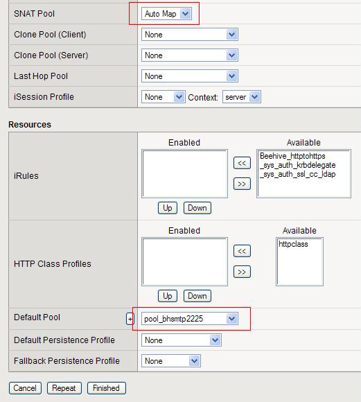
27 5. In the Address field, type the IP address of this virtual server. The MAA example uses In the Service Port field, type 25. Note: In our example, the SMTP pool is configured for port 2225, but the Virtual Server is configured for port 25. You may need to modify these port numbers to match your Beehive installation. 7. From the Configuration list, select Advanced. The Advanced configuration options display. 8. In the Type field, ensure the default setting, Standard, is selected. 9. From the Protocol Profile (Client) list select the name of the profile you created in the Creating a TCP profile section. The MAA example selected tcp_bhsmtp Leave the Protocol Profile (Server) option at the default setting. 11. Change the SNAT Pool setting to Auto Map. 12. In the Resources section, from the Default Pool list, select the pool you created in the Create the SMTP pool step. The MAA example selected pool_bhsmtp Click Finished. 26
28 27
29 Step 5: Create the SMTPS virtual server This step configures a SMTPS virtual server that references the monitor, profiles, and pool that you created in the preceding procedures. Note: The creation of a virtual server using the SSL offload features of BIG-IP is optional. If you are planning to run any Beehive services with SSL Offload, you MUST configure the BIG-IP for SSL before creating any SSL enabled virtual servers. Please see the Appendix for full details on configuring SSL on the BIG-IP. 1. On the Main tab of the BIG-IP Configuration Utility, expand Local Traffic, and then click Virtual Servers. 2. In the upper right portion of the Virtual Servers screen, click Create. 3. In the Name field on the New Virtual Server screen, enter a unique name for this virtual server. The MAA example uses vs_bhsmtps In the Destination section, select the Host option. 5. In the Address field, type the IP address of this virtual server. The MAA example uses In the Service Port field, type 465. Note: In our example, the SMTP pool is configured for port 2225, but the Virtual Server is configured for port 465. You may need to modify the port numbers to match your Beehive installation. 7. From the Configuration list, select Advanced. 8. In the Type field, ensure the default setting, Standard, is selected. 9. From the Protocol Profile (Client) list select the name of the profile you created in the Creating a TCP profile section. The MAA example selected tcp_bhsmtp Leave the Protocol Profile (Server) option at the default setting. 11. From the SSL Profile (Client) list, select the name of the SSL profile you created in the Create a Beehive Client SSL profile section. The MAA example selected Beehive_clientssl. 12. Change the SNAT Pool setting to Auto Map. 13. In the Resources section, from the Default Pool list, select the pool you created in the Create the SMTP pool step The MAA example selected pool_bhsmtp Click Finished. 28
30 29
31 Configuring Oracle Beehive Transport Protocol (Port 21401) This section provides step-by-step procedures to configure F5 to support the Oracle Beehive Transport Protocol (BTP) port for the Oracle Beehive system. Step 1: Create and configure a health monitor for the BTP service 1. On the Main tab of the BIG-IP Configuration Utility, expand Local Traffic, and click Monitors. 2. On the Monitors screen, click Create. 3. In the Name field on the New Monitor screen, enter a unique name for this Monitor. The MAA example uses mon_bhbtp From the Type list, select TCP. The Monitor configuration options display. 5. From the Configuration list, select Advanced. In the Configuration section, enter values in the Interval and Timeout fields. The recommendation is to specify a minimum 1:3 +1 ratio between the interval and the timeout. The example in this white paper uses an Interval of 30 and a Timeout of In the Alias Service Port box, enter All other configuration settings are optional, configure as applicable for your deployment. 8. Click Finished. Step 2: Create a new TCP profile for the BTP This step creates a TCP profile. In our example, the TCP profile is based on the default TCP profile and uses all of default settings. You can configure these options as appropriate for your network. 1. On the Main tab of the BIG-IP Configuration Utility, expand Local Traffic. 2. Click Profiles. The HTTP Profiles screen opens. 3. On the Menu bar, from the Protocol menu, select TCP. 4. In the upper right portion of the screen, click Create. The New TCP Profile screen opens. 5. In the Name field, enter a unique name for this profile. The MAA example uses tcp_bhbtp
32 6. In the Idle Timeout row, check Custom. In the second s field, enter Modify any of the settings as applicable for your network. See the online help for more information about the configuration options. The MAA example uses the default settings. 8. Click Finished. Step 3: Create the BTP pool To create the BTP pool: 1. On the Main tab of the BIG-IP Configuration Utility, expand Local Traffic, and then click Pools. 2. In the upper right portion of the Pools screen, click Create. The New Pool screen opens. Note: For more (optional) pool configuration settings, select Advanced from the Configuration list. Configure the settings, as applicable, for your network. 3. In the Name field, enter a unique name for your pool. The MAA example uses pool_bhbtp In the Health Monitors section, select the name of the monitor you created in the Create the BTP health monitor step, and click Add (<<). The MAA example selected mon_bhbtp From the Load Balancing Method list, choose your preferred load balancing method. (Different load balancing methods may yield optimal results for a particular network.) In our example, we selected Least Connections (member). 6. For this pool, we leave the Priority Group Activation Disabled. 7. In the New Members section, make sure the New Address option is selected. 8. In the Address field, add the first server to the pool. The MAA example uses In the Service Port field, type the service port you want to use for this device, or specify a service by choosing a service name from the list. The MAA example uses Click Add to add the member to the list. 11. Repeat the three previous steps for each server you want to add to the pool. The MAA example in this white paper repeats this step once to add the remaining server:
33 12. Click Finished. Step 4: Create the BTP virtual server This step configures a BTP virtual server that references the monitor, profiles, and pool that you created in the preceding procedures. 1. On the Main tab of the BIG-IP Configuration Utility, expand Local Traffic, and then click Virtual Servers. 2. In the upper right portion of the Virtual Servers screen, click Create. 3. In the Name field on the New Virtual Server screen, enter a unique name for this virtual server. The MAA example uses vs_bhbtp In the Destination section, select the Host option. 5. In the Address field, type the IP address of this virtual server. The MAA example uses In the Service Port field, type From the Configuration list, select Advanced. The Advanced configuration options appear. 8. In the Type field, ensure the default setting, Standard, is selected. 9. From the Protocol Profile (Client) list select the name of the profile you created in the Create a TCP profile for BTP step. The MAA example selected tcp_bhsmtp Leave the Protocol Profile (Server) option at the default setting. 11. Change the SNAT Pool setting to Auto Map. 12. In the Resources section, from the Default Pool list, select the pool you created in the Create the BTP pool step The MAA example selected pool_bhbtp Click Finished. Configuring Oracle Secure BTPS (Port 5224) This section provides step-by-step procedures to configure F5 to support the Secure Oracle Beehive Transport Protocol (BTPS) port for the Oracle Beehive system. Step 1: Create and configure a health monitor for the BTPS service 1. On the Main tab of the BIG-IP Configuration Utility, expand Local Traffic, and click Monitors. 32
34 2. On the Monitors screen, click Create. 3. In the Name field on the New Monitor screen, enter a unique name for this Monitor. The MAA example uses mon_bhbtps From the Type list, select TCP. The Monitor configuration options display. 5. From the Configuration list, select Advanced. In the Configuration section, enter values in the Interval and Timeout fields. The recommendation is to specify a minimum 1:3 +1 ratio between the interval and the timeout. The example in this white paper uses an Interval of 30 and a Timeout of In the Alias Service Port box, enter All other configuration settings are optional, configure as applicable for your deployment. 8. Click Finished. Step 2: Create a new TCP profile for the BTPS This step creates a TCP profile. In our example, the TCP profile is based on the default TCP profile and uses all of default settings. You can configure these options as appropriate for your network. 1. On the Main tab of the BIG-IP Configuration Utility, expand Local Traffic. 2. Click Profiles. The HTTP Profiles screen opens. 3. On the Menu bar, from the Protocol menu, select TCP. 4. In the upper right portion of the screen, click Create. The New TCP Profile screen opens. 5. In the Name field, enter a unique name for this profile. The MAA example uses tcp_bhbtps In the Idle Timeout row, check Custom. In the second s field, enter Modify any of the settings as applicable for your network. See the online help for more information about the configuration options. The MAA example uses the default settings. 8. Click Finished. 33
35 Step 3: Create the BTPS pool To create the BTPS pool: 1. On the Main tab of the BIG-IP Configuration Utility, expand Local Traffic, and then click Pools. 2. In the upper right portion of the Pools screen, click Create. The New Pool screen opens. Note: For more (optional) pool configuration settings, select Advanced from the Configuration list. Configure the settings, as applicable, for your network. 3. In the Name field, enter a unique name for your pool. The MAA example uses pool_bhbtps In the Health Monitors section, select the name of the monitor you created in the Create the BTPS health monitor step, and click Add (<<). The MAA example selected mon_bhbtps From the Load Balancing Method list, choose your preferred load balancing method. (Different load balancing methods may yield optimal results for a particular network.) In our example, we selected Least Connections (member). 6. For this pool, we leave the Priority Group Activation set to Disabled. 7. In the New Members section, make sure the New Address option is selected. 8. In the Address field, add the first server to the pool. The MAA example uses In the Service Port field, type the service port you want to use for this device, or specify a service by choosing a service name from the list. The MAA example uses Click Add to add the member to the list. 11. Repeat the three previous steps for each server you want to add to the pool. The MAA example in this white paper repeats this step once to add the remaining server: Click Finished. Step 4: Create the BTPS virtual server This step configures a BTPS virtual server that references the monitor, profiles, and pool that you created in the preceding procedures. 34
36 1. On the Main tab of the BIG-IP Configuration Utility, expand Local Traffic, and then click Virtual Servers. 2. In the upper right portion of the Virtual Servers screen, click Create. 3. In the Name field on the New Virtual Server screen, enter a unique name for this virtual server. The MAA example uses vs_bhbtps In the Destination section, select the Host option. 5. In the Address field, type the IP address of this virtual server. The MAA example uses In the Service Port field, type From the Configuration list, select Advanced. The Advanced configuration options appear. 8. In the Type field, ensure the default setting, Standard, is selected. 9. From the Protocol Profile (Client) list select the name of the profile you created in the Create a TCP profile for BTPS step. The MAA example selected tcp_bhbtps Leave the Protocol Profile (Server) option at the default setting. 11. Change the SNAT Pool setting to Auto Map. 12. In the Resources section, from the Default Pool list, select the pool you created in the Create the BTPS pool step. The MAA example selected pool_bhbtps Click Finished. Configuring XMPP Beehive Presence (Port 5222) This section provides step-by-step procedures to configure F5 to support the Beehive Presence Service for the Oracle Beehive system. Step 1: Create and configure a health monitor for the Beehive Presence (XMPP) service 1. On the Main tab of the BIG-IP Configuration Utility, expand Local Traffic, and click Monitors. 2. On the Monitors screen, click Create. 3. In the Name field on the New Monitor screen, enter a unique name for this Monitor. The MAA example uses mon_bhxmpp From the Type list, select TCP. 35
37 The Monitor configuration options appear. 5. From the Configuration list, select Advanced. In the Configuration section, enter values in the Interval and Timeout fields. The recommendation is to specify a minimum 1:3 +1 ratio between the interval and the timeout. The example in this white paper uses an Interval of 30 and a Timeout of In the Alias Service Port box, enter All other configuration settings are optional, configure as applicable for your deployment. 8. Click Finished. Step 2: Create a new TCP profile for the XMPP service This step creates a TCP profile. You can configure these options as appropriate for your network. 1. On the Main tab of the BIG-IP Configuration Utility, expand Local Traffic. 2. Click Profiles. The HTTP Profiles screen opens. 3. On the Menu bar, from the Protocol menu, select TCP. 4. In the upper right portion of the screen, click Create. The New TCP Profile screen opens. 5. In the Name field, enter a unique name for this profile. The MAA example uses tcp_bhxmpp In the Idle Timeout row, check Custom. In the second s field, enter Modify any of the settings as applicable for your network. See the online help for more information about the configuration options. The MAA example uses the default settings. 8. Click Finished. Step 3: Create the XMPP pool The next step in this configuration is to create a pool on the BIG-IP system. A BIG-IP pool is a set of devices grouped together to receive traffic according to a load balancing method. The MAA example configuration created one pool for the Beehive XMPP devices. To create the XMPP pool: 36
38 1. On the Main tab of the BIG-IP Configuration Utility, expand Local Traffic, and then click Pools. 2. In the upper right portion of the Pools screen, click Create. The New Pool screen opens. Note: For more (optional) pool configuration settings, select Advanced from the Configuration list. Configure the settings, as applicable, for your network. 3. In the Name field, enter a unique name for your pool. The MAA example uses pool_bhxmpp In the Health Monitors section, select the name of the monitor you created in the Create the XMPP health monitor step, and click Add (<<). The MAA example selected mon_bhxmpp From the Load Balancing Method list, choose your preferred load balancing method. (Different load balancing methods may yield optimal results for a particular network.) In our example, we selected Least Connections (member). 6. For this pool, we leave the Priority Group Activation setting at Disabled. 7. In the New Members section, make sure the New Address option is selected. 8. In the Address field, add the first server to the pool. The MAA example uses In the Service Port field, type the service port you want to use for this device, or specify a service by choosing a service name from the list. The MAA example uses Click Add to add the member to the list. 11. Repeat the three previous steps for each server you want to add to the pool. The MAA example in this white paper repeats this step once to add the remaining server: Click Finished. Step 4: Create the XMPP virtual server This step configures an XMPP virtual server that references the monitor, profiles, and pool that you created in the preceding procedures. 1. On the Main tab of the BIG-IP Configuration Utility, expand Local Traffic, and then click Virtual Servers. 2. In the upper right portion of the Virtual Servers screen, click Create. 37
39 3. In the Name field on the New Virtual Server screen, enter a unique name for this virtual server. The MAA example uses vs_bhxmpp In the Destination section, select the Host option. 5. In the Address field, enter the IP address of this virtual server. The MAA example uses In the Service Port field, enter From the Configuration list, select Advanced. The Advanced configuration options appear. 8. In the Type field, ensure the default setting, Standard, is selected. 9. From the Protocol Profile (Client) list select the name of the profile you created in the Create a TCP profile for XMPP step. The MAA example selected tcp_bhxmpp Leave the Protocol Profile (Server) option at the default setting. 11. Change the SNAT Pool setting to Auto Map. 12. In the Resources section, from the Default Pool list, select the pool you created in the Create the XMPP pool step. The MAA example selected pool_bhxmpp Click Finished. Step 5: Create the XMPPS virtual server This step configures an XMPPS virtual server that references the monitor, profiles, and pool created in the preceding procedures. Note: The creation of a virtual server using the SSL offload features of BIG-IP is optional. If you plan to run any Beehive services with SSL Offload, you must configure the BIG-IP for SSL before creating any SSL enabled virtual servers. See Appendix B for full details about configuring SSL on the F5 BIG-IP. To create the XMPPS virtual server: 1. On the Main tab of the BIG-IP Configuration Utility, expand Local Traffic, and then click Virtual Servers. 2. In the upper right portion of the Virtual Servers screen, click Create. 3. In the Name box on the New Virtual Server screen, type a unique name for this virtual server. In the MAA example, we entered vs_bhxmpps In the Destination section, select the Host option. 38
40 5. In the Address field, type the IP address of this virtual server. The MAA example used In the Service Port field, type Note: In the MAA example, the XMPP pool is configured for port 5222, but the Virtual Server is configured for port You may need to modify the port numbers to match your Beehive installation. 7. From the Configuration list, select Advanced. The Advanced configuration options appear. 8. In the Type field, ensure the default setting, Standard, is selected. 9. From the Protocol Profile (Client) list select the name of the profile you created in the Create a new TCP profile for the XMPP service step. The MAA example selected tcp_bhxmpp Leave the Protocol Profile (Server) option at the default setting. 11. From the SSL Profile (Client) list, select the name of the SSL profile you created in the Create a Beehive Client SSL profile section. The MAA example selected Beehive_clientssl. 12. Change the SNAT Pool setting to Auto Map. 13. In the Resources section, from the Default Pool list, select the pool you created in the "Create the XMPP pool" step. The MAA example uses pool_bhxmpp Click Finished. Configuring FTP Service (Port 2121) This section describes the procedure to configure the F5 to support the Beehive FTP Service for the Oracle Beehive system. This section provides step-by-step procedures to configure F5 to support the Beehive Presence Service for the Oracle Beehive system. Step 1: Create and configure a health monitor for the FTP service 1. On the Main tab of the BIG-IP Configuration Utility, expand Local Traffic, and click Monitors. 2. On the Monitors screen, click Create. 3. In the Name field on the New Monitor screen, enter a unique name for this Monitor. The MAA example uses mon_bhftp From the Type list, select FTP. 39

41 The Monitor configuration options appear. 5. From the Configuration list, select Advanced. In the Configuration section, enter values in the Interval and Timeout fields. The recommendation is to specify a minimum 1:3 +1 ratio between the interval and the timeout. The example in this white paper uses an Interval of 30 and a Timeout of In the Username field, enter the name of a dedicated monitor account. The MAA example uses F5monitor. 7. In the Password field, enter a password for the F5monitor account. The MAA example uses F5monitor. 8. In the Path/Filename field, enter the path and file for testing downloads. The MAA example uses: /Oracle/F5monitor's Personal Workspace/Documents/monitor.txt 9. In the Alias Service Port box, enter All other configuration settings are optional. Configure them, as applicable, for your deployment. 11. Click Finished. 40
42 Step 2: Create a new TCP profile for the FTP service This step creates a TCP profile for the MAA example configuration. The MAA example bases the TCP profile on the default TCP profile, and using the default settings for all of the options. You should configure the options appropriately for your network. 1. On the Main tab of the BIG-IP Configuration Utility, expand Local Traffic. 2. Click Profiles. The HTTP Profiles screen opens. 3. On the Menu bar, from the Protocol menu, select TCP. 4. In the upper right portion of the screen, click Create. The New TCP Profile screen opens. 5. In the Name field, enter a unique name for this profile. The MAA example uses tcp_bhftp In the Idle Timeout row, check Custom. In the second s field, enter Modify any of the settings as applicable for your network. See the online help for more information about the configuration options. The MAA example uses the default settings. 8. Click Finished. Step 3: Create the FTP pool The next step in this configuration is to create a pool on the BIG-IP system. A BIG-IP pool is a set of devices grouped together to receive traffic according to a load balancing method. The MAA example configuration created one pool for the Beehive FTP devices. To create the FTP pool: 1. On the Main tab of the BIG-IP Configuration Utility, expand Local Traffic, and then click Pools. 2. In the upper right portion of the Pools screen, click Create. The New Pool screen opens. Note: For more (optional) pool configuration settings, select Advanced from the Configuration list. Configure the settings, as applicable, for your network. 3. In the Name field, enter a unique name for your pool. The MAA example uses pool_bhftp
43 4. In the Health Monitors section, select the name of the monitor you created in the Create and configure the FTP health monitor step, and click Add (<<). The MAA example selected mon_bhxmpp From the Load Balancing Method list, choose your preferred load balancing method. (Different load balancing methods may yield optimal results for a particular network.) The MAA example selected Least Connections (member). 6. For this pool, we leave the Priority Group Activation setting at Disabled. 7. In the New Members section, make sure the New Address option is selected. 8. In the Address field, add the first server to the pool. The MAA example uses In the Service Port field, type the service port you want to use for this device, or specify a service by choosing a service name from the list. The MAA example uses Click Add to add the member to the list. 11. Repeat the three previous steps for each server you want to add to the pool. The MAA example in this white paper repeats this step once to add the remaining server: Click Finished. Step 4: Create the FTP virtual server This step configures an FTP virtual server that references the monitor, profiles, and pool that you created in the preceding procedures. 1. On the Main tab of the BIG-IP Configuration Utility, expand Local Traffic, and then click Virtual Servers. 2. In the upper right portion of the Virtual Servers screen, click Create. 3. In the Name field on the New Virtual Server screen, enter a unique name for this virtual server. The MAA example uses vs_bhftp In the Destination section, select the Host option. 5. In the Address field, enter the IP address of this virtual server. The MAA example uses In the Service Port field, enter From the Configuration list, select Advanced. The Advanced configuration options display. 42
44 8. In the Type field, ensure the default setting, Standard, is selected. 9. From the Protocol Profile (Client) list select the name of the profile you created in the Create a TCP profile for FTP step. The MAA example selected tcp_bhftp Leave the Protocol Profile (Server) option at the default setting. 11. Change the SNAT Pool setting to Auto Map. 12. In the Resources section, from the Default Pool list, select the pool you created in the Create the FTP pool step. The MAA example selected pool_bhftp Click Finished. Step 5: Create the FTPS virtual server This step configures an FTPS virtual server that references the monitor, profiles, and pool created in the preceding procedures. Note: The creation of a virtual server using the SSL offload features of BIG-IP is optional. If you plan to run any Beehive services with SSL Offload, you must configure the BIG-IP for SSL before creating any SSL enabled virtual servers. See Appendix B for full details about configuring SSL on the F5 BIG-IP. To create the FTPS virtual server: 1. On the Main tab of the BIG-IP Configuration Utility, expand Local Traffic, and then click Virtual Servers. 2. In the upper right portion of the Virtual Servers screen, click Create. 3. In the Name box on the New Virtual Server screen, type a unique name for this virtual server. In the MAA example, we entered vs_bhftps In the Destination section, select the Host option. 5. In the Address field, type the IP address of this virtual server. The MAA example used In the Service Port field, type 990. Note: In the MAA example, the FTPS pool is configured for port 2121, but the Virtual Server is configured for port 990. You may need to modify the port numbers to match your Beehive installation. 7. From the Configuration list, select Advanced. The Advanced configuration options appear. 8. In the Type field, ensure the default setting, Standard, is selected. 43
45 9. From the Protocol Profile (Client) list, select the name of the profile you created in the Create a new TCP profile for the FTP service step.. The MAA example selected tcp_bhftp Leave the Protocol Profile (Server) option at the default setting. 11. Change the SNAT Pool setting to Auto Map. 12. In the Resources section, from the Default Pool list, select the pool you created in the "Create the FTP pool" step. The MAA example uses pool_bhftp Click Finished Configuring Beehive HTTP and HTTPS (Port 7777) This section provides step-by-step procedures to configure F5 to support the Standard Beehive HTTP Service for the Oracle Beehive system. Step 1: Create and configure a health monitor for the Beehive HTTP service 1. On the Main tab of the BIG-IP Configuration Utility, expand Local Traffic, and click Monitors. 2. On the Monitors screen, click Create. 3. In the Name field on the New Monitor screen, enter a unique name for this Monitor. The MAA example uses mon_bhhttp From the Type list, select HTTP. The Monitor configuration options display. 5. From the Configuration list, select Advanced. In the Configuration section, enter values in the Interval and Timeout fields. The recommendation is to specify a minimum 1:3 +1 ratio between the interval and the timeout. The MAA example in this white paper uses an Interval of 30 and a Timeout of In the Alias Service Port box, enter All other configuration settings are optional, configure as applicable for your deployment. 8. Click Finished. Step 2: Create a new TCP profile for the Beehive HTTP service This step creates a TCP profile for the MAA example configuration. The MAA example bases the TCP profile on the default TCP profile, and using the default settings for all of the options. You should configure the options appropriately for your network. 44
46 1. On the Main tab of the BIG-IP Configuration Utility, expand Local Traffic. 2. Click Profiles. The HTTP Profiles screen opens. 3. On the Menu bar, from the Protocol menu, select TCP. 4. In the upper right portion of the screen, click Create. The New TCP Profile screen opens. 5. In the Name field, enter a unique name for this profile. The MAA example uses tcp_bhhttp In the Idle Timeout row, check Custom. In the second s field, enter Modify any of the settings as applicable for your network. See the online help for more information about the configuration options. The MAA example uses the default settings. 8. Click Finished. Step 3: Create the Beehive HTTP pool The next step in this configuration is to create a pool on the BIG-IP system. A BIG-IP pool is a set of devices grouped together to receive traffic according to a load balancing method. The MAA example configuration created one pool for the Beehive HTTP devices. To create the HTTP pool: 1. On the Main tab of the BIG-IP Configuration Utility, expand Local Traffic, and then click Pools. 2. In the upper right portion of the Pools screen, click Create. The New Pool screen opens. Note: For more (optional) pool configuration settings, select Advanced from the Configuration list. Configure the settings, as applicable, for your network. 3. In the Name field, enter a unique name for your pool. The MAA example uses pool_bhhttp In the Health Monitors section, select the name of the monitor you created in the Create and configure the (Unsecure) Beehive HTTP health monitor step, and click Add (<<). The MAA example selected mon_bhhttp From the Load Balancing Method list, choose your preferred load balancing method. (Different load balancing methods may yield optimal results for a 45
47 particular network.) The MAA example selected Least Connections (member). 6. For this pool, we leave the Priority Group Activation setting at Disabled. 7. In the New Members section, make sure the New Address option is selected. 8. In the Address field, add the first server to the pool. The MAA example uses In the Service Port field, type the service port you want to use for this device, or specify a service by choosing a service name from the list. The MAA example uses Click Add to add the member to the list. 11. Repeat the three previous steps for each server you want to add to the pool. The MAA example in this white paper repeats this step once to add the remaining server: Click Finished. Step 4: Create the Beehive HTTP virtual server This step configures a Beehive HTTP virtual server that references the monitor, profiles, and pool that you created in the preceding procedures. 1. On the Main tab of the BIG-IP Configuration Utility, expand Local Traffic, and then click Virtual Servers. 2. In the upper right portion of the Virtual Servers screen, click Create. 3. In the Name field on the New Virtual Server screen, enter a unique name for this virtual server. The MAA example uses vs_bhhttp In the Destination section, select the Host option. 5. In the Address field, enter the IP address of this virtual server. The MAA example uses In the Service Port field, enter From the Configuration list, select Advanced. The Advanced configuration options display. 8. In the Type field, ensure the default setting, Standard, is selected. 9. From the Protocol Profile (Client) list select the name of the profile you created in the Create a TCP profile for Beehive HTTP Service step. The MAA example selected tcp_bhhttp
48 10. Leave the Protocol Profile (Server) option at the default setting. 11. From the HTTP Profile list, select http. Note: If the clients will be attaching to the Beehive HTTP services over a WAN (wide-area network), select the http-wan-optimized-compression profile. 12. Change the SNAT Pool setting to Auto Map. 13. In the Resources section, from the Available list, select the irule you created in the Creating the Beehive Redirect irule section. In the MAA example, we select Beehive_httptohttps, and click and click Add (<<) to add it to the Enabled list. This irule redirects all clients to the SSL virtual server for Beehive HTTP on port From the Default Pool list, select the pool you created in the Create the Beehive HTTP pool step. The MAA example selected pool_bhhttp Click Finished. 47

49 48
50 Step 5: Create the HTTPS virtual server This step configures an HTTPS virtual server that references the monitor, profiles, and pool created in the preceding procedures. Note: The creation of a virtual server using the SSL offload features of BIG-IP is optional. If you plan to run any Beehive services with SSL Offload, you must configure the BIG-IP for SSL before creating any SSL enabled virtual servers. See Appendix B for full details about configuring SSL on the F5 BIG-IP. To create the HTTPS virtual server: 1. On the Main tab of the BIG-IP Configuration Utility, expand Local Traffic, and then click Virtual Servers. 2. In the upper right portion of the Virtual Servers screen, click Create. 3. In the Name box on the New Virtual Server screen, type a unique name for this virtual server. In the MAA example, we entered vs_bhhttps In the Destination section, select the Host option. 5. In the Address field, type the IP address of this virtual server. The MAA example used In the Service Port field, type From the Configuration list, select Advanced. The Advanced configuration options appear. 8. In the Type field, ensure the default setting, Standard, is selected. 9. From the Protocol Profile (Client) list, select the name of the profile you created in the Create a new TCP profile for the Beehive HTTP service step.. The MAA example selected tcp_bhhttp Leave the Protocol Profile (Server) option at the default setting. 11. From the SSL Profile (Client) list, select the name of the SSL profile you created in the Create a Beehive Client SSL profile section. The MAA example selected Beehive_clientssl. 12. From the HTTP Profile list, select http. Note: If the clients will be attaching to the Beehive HTTPS services over a WAN (wide-area network), select the http-wan-optimized-compression profile. 13. Change the SNAT Pool setting to Auto Map. 14. In the Resources section, from the Default Pool list, select the pool you created in the "Create the HTTP pool" step. The MAA example uses pool_bhhttp


51 15. Click Finished 50
52 Configuring Beekeeper (Port 7779) This section provides step-by-step procedures to configure F5 to support the Standard Beekeeper Service for the Oracle Beehive system. Step 1: Create and configure a health monitor for the Beekeeper service 1. On the Main tab of the BIG-IP Configuration Utility, expand Local Traffic, and click Monitors. 2. On the Monitors screen, click Create. The New Monitor screen opens. 3. In the Name field on the New Monitor screen, enter a unique name for this Monitor. The MAA example uses mon_bhbeekeeper From the Type list, select HTTP. The Monitor configuration options display. 5. From the Configuration list, select Advanced. In the Configuration section, enter values in the Interval and Timeout fields. The recommendation is to specify a minimum 1:3 +1 ratio between the interval and the timeout. The MAA example in this white paper uses an Interval of 30 and a Timeout of In the Alias Service Port box, enter All other configuration settings are optional, configure as applicable for your deployment. 8. Click Finished. Step 2: Create a new TCP profile for the unsecure Beekeeper service This step creates a TCP profile for the MAA example configuration. The MAA example bases the TCP profile on the default TCP profile, and using the default settings for all of the options. You should configure the options appropriately for your network. 1. On the Main tab of the BIG-IP Configuration Utility, expand Local Traffic and click Profiles. The HTTP Profiles screen opens. 2. On the Menu bar, from the Protocol menu, select TCP. 3. In the upper right portion of the screen, click Create. The New TCP Profile screen opens. 4. In the Name field, enter a unique name for this profile. The MAA example uses tcp_bhbeekeeper

53 5. In the Idle Timeout row, check Custom. In the second s field, enter Modify any of the settings as applicable for your network. See the online help for more information about the configuration options. The MAA example uses the default settings. 7. Click Finished. Step 3: Create a new Beekeeper cookie persistence profile This step creates a Cookie Persistence profile based on the default profile. We recommend using the default cookie method for this profile (HTTP cookie insert), but you can change other settings, such as specifying a cookie expiration. 1. On the Main tab of the BIG-IP Configuration Utility, expand Local Traffic and click Profiles. The HTTP Profiles screen opens. 2. On the Menu bar, from the Protocol menu, click Persistence. 3. In the upper right portion of the Persistence Profiles screen, click Create. 4. In the Name field on the New Persistence Profile screen, enter a unique name for this profile. The MAA example uses cookie_beekeeper. 5. From the Persistence Type list, select Cookie. The configuration options for cookie persistence display. 6. Click Finished. For more information about creating or modifying profiles, or for general information about applying profiles, see the F5 BIG-IP Product Documentation [3] at 52
54 Step 4: Create the Beekeeper pool The next step in this configuration is to create a pool on the BIG-IP system. A BIG-IP pool is a set of devices grouped together to receive traffic according to a load balancing method. The MAA example configuration created one pool for the Beehive HTTP devices. To create the Beekeeper pool: 1. On the Main tab of the BIG-IP Configuration Utility, expand Local Traffic, and then click Pools. 2. In the upper right portion of the Pools screen, click Create. The New Pool screen opens. Note: For more (optional) pool configuration settings, select Advanced from the Configuration list. Configure the settings, as applicable, for your network. 3. In the Name field, enter a unique name for your pool. The MAA example uses pool_bhbeekeeper In the Health Monitors section, select the name of the monitor you created in the Create and configure the (Unsecure) Beekeeper health monitor step, and click Add (<<). The MAA example selected mon_bhbeekeeper From the Load Balancing Method list, choose your preferred load balancing method. (Different load balancing methods may yield optimal results for a particular network.) The MAA example selected Least Connections (member). 6. For this pool, the MAA example left the Priority Group Activation setting at Disabled. 7. In the New Members section, make sure the New Address option is selected. 8. In the Address field, add the first server to the pool. The MAA example uses In the Service Port field, type the service port you want to use for this device, or specify a service by choosing a service name from the list. The MAA example uses Click Add to add the member to the list. 11. Repeat the three previous steps for each server you want to add to the pool. The MAA example in this white paper repeats this step once to add the remaining server: Click Finished. 53
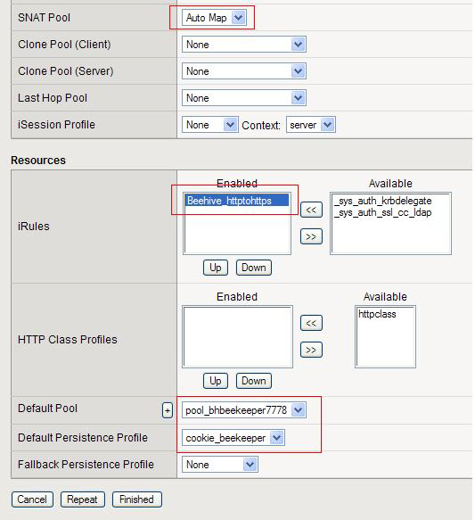
55 Step 5: Create the unsecure Beekeeper HTTP virtual server This step configures an unsecure Beekeeper HTTP virtual server that references the monitor, profiles, and pool that you created in the preceding procedures. 1. On the Main tab of the BIG-IP Configuration Utility, expand Local Traffic, and then click Virtual Servers. 2. In the upper right portion of the Virtual Servers screen, click Create. 3. In the Name field on the New Virtual Server screen, enter a unique name for this virtual server. The MAA example uses vs_bhbeekeeper In the Destination section, select the Host option. 5. In the Address field, enter the IP address of this virtual server. The MAA example uses In the Service Port field, enter From the Configuration list, select Advanced. The Advanced configuration options appear. 8. In the Type field, ensure the default setting, Standard, is selected. 9. From the Protocol Profile (Client) list select the name of the profile you created in the Create a TCP profile for Beekeeper step. The MAA example selected tcp_bhbeekeeper Leave the Protocol Profile (Server) option at the default setting. 11. From the HTTP Profile list, select http. 12. Change the SNAT Pool setting to Auto Map. 13. In the Resources section, from the Available list, select the select the irule you created in the Creating the Beehive Redirect irule section. In the MAA example, we select Beehive_httptohttps, and click (<<) to add it to the Enabled list. This irule redirects all clients to the SSL virtual server for Beekeeper on port From the Default Pool list, select the pool you created in the Create the Beekeeper pool step. The MAA example selected pool_bhbeekeeper From the Default Persistence Profile list, select the Cookie profile you created in the Create the cookie persistence profile for Beekeeper step. In our example, we select cookie_beekeeper. 16. Click Finished. 54
56 55
57 Step 6: Create the Beekeeper HTTP Secure virtual server This step configures a Beekeeper Secure virtual server that references the monitor, profiles, and pool created in the preceding procedures. Note: The creation of a virtual server using the SSL offload features of BIG-IP is optional. If you plan to run any Beehive services with SSL Offload, you must configure the BIG-IP for SSL before creating any SSL enabled virtual servers. See Appendix B for full details about configuring SSL on the F5 BIG-IP. To create the Beekeeper Secure virtual server: 1. On the Main tab of the BIG-IP Configuration Utility, expand Local Traffic, and then click Virtual Servers. 2. In the upper right portion of the Virtual Servers screen, click Create. 3. In the Name box on the New Virtual Server screen, type a unique name for this virtual server. In the MAA example, we entered vs_bhbeekeepers In the Destination section, select the Host option. 5. In the Address field, type the IP address of this virtual server. The MAA example used In the Service Port field, type From the Configuration list, select Advanced. The Advanced configuration options appear. 8. In the Type field, ensure the default setting, Standard, is selected. 9. From the Protocol Profile (Client) list, select the name of the profile you created in the Create a new TCP profile for the Beekeeper service step.. The MAA example selected tcp_bhbeekeeper Leave the Protocol Profile (Server) option at the default setting. 11. From the SSL Profile (Client) list, select the name of the SSL profile you created in the Create a Beekeeper Client SSL profile section. The MAA example selected Beekeeper_clientssl. Make sure you use the Beekeeper SSL profile, and not the Beehive SSL profile. 12. From the HTTP Profile list, select http. 13. Change the SNAT Pool setting to Auto Map. 56


58 14. In the Resources section, from the Default Pool list, select the pool you created in the "Create the Beekeeper pool" step. The MAA example uses pool_bhbeekeeper Click Finished. 57

59 F5 Monitor Configuration Summary After finishing the configuration of all Beehive services, you should have a list of monitors similar to the one in the following screenshot from the MAA example. F5 TCP Profile Configuration Summary After finishing the configuration of all Beehive services, you should have a list of TCP profiles similar to the one in the following screenshot from the MAA example. 58


60 F5 Persistence Profile Configuration Summary After finishing the configuration of all Beehive services, you should have a list of persistence profiles similar to the one in the following screenshot from the MAA example. 59

61 F5 Pool Configuration Summary After finishing the configuration of all Beehive services, you should have a list of pools similar to the one in the following screenshot from the MAA example. 60

62 F5 Virtual Server Configuration Summary After finishing the configuration of all Beehive services, you should have a list of virtual servers with IP addresses and port numbers similar to the one in the following screenshot from the MAA example. 61
63 Configure Beehive to Work with the F5 BIG-IP LTM Follow the steps in this section to configure Beehive to work with the F5 BIG-IP LTM. Perform the tasks in this section before you clone any other application nodes so that you do not have to duplicate these steps on the other application nodes. At the end of these steps, be sure to activate the changes and commit them to the local configuration. Set the Virtual Server and Ports Set the ports to match Table 2 as follows beectl list_properties --component _VIRTUAL_SERVER beectl modify_property --component _VIRTUAL_SERVER --name ServerName --value beehive.example.com beectl modify_property --component _ Service:SMTPProperties --name Port --value 2225 beectl modify_property --component _VIRTUAL_SERVER --name SmtpPort --value 2225 beectl modify_property --component _ Service:IMAPProperties --name Port --value 5143 beectl modify_property --component _VIRTUAL_SERVER --name ImapPort --value 5143 Note: The HttpPort is set to the Oracle HTTP Server (OHS) virtual port. Since SSL is terminated at the BigIP LTM, set the HttpPort to 443 and ensure that SSL is enabled for the Beehive virtual server. Enabling SSL is for redirect URL s that copy the settings that the active request used. To see what the HTTP listening port is set to, see the Setting the HTTP and HTTPS Listening Ports section. beectl modify_property --component _VIRTUAL_SERVER --name HttpPort --value 443 beectl modify_property --component _VIRTUAL_SERVER --name HttpSslEnabled --value true beectl list_properties --component _VIRTUAL_SERVER Property Name Property Value *ImapPort *SmtpPort Alias _VIRTUAL_SERVER BtiClientPort BtiSecureClientPort FtpPort *HttpPort
64 *HttpSslEnabled false HttpSslPort IPAddress ImapSslEnabled false ImapSslPort *ServerName beehive.example.com SmtpAuthRequired false SmtpSslEnabled false SmtpSslPort XmppPort XmppSslEnabled false XmppSslPort Note:- An asterisk (*) indicates that property value is changed and change is not yet activated. Set the HTTP Listening Port Setting the HTTP listening port is necessary only if the current listening port is not what you want. 1. Get the Beehive instance name: beectl list_components --type BeehiveInstance Component type Component identifier BeehiveInstance beehive_instance_maatst.bhmt01.example.com Get the OHS component name: beectl list_properties --component beehive_instance_maatst.bhmt01.example.com --name HttpServer Property name Property value HttpServer ohs_maatst.bhmt01.example.com Get the current HTTP listener port: beectl list_properties --component ohs_maatst.bhmt01.example.com --name HttpListenPort
65 Property name Property value HttpListenPort Change the HTTP listening port: beectl modify_property --component ohs_maatst.bhmt01.example.com --name HttpListenPort --value Activate the configuration: beectl activate_configuration 6. Modify the local configuration files: beectl modify_local_configuration_files Set Beehive HTTP Server for SSL Termination 1. Set the SslTerminatedByLoadBalancer property of the HttpServerCluster component to true: beectl modify_property \ --component _current_site:httpservercluster \ --name SslTerminatedByLoadBalancer \ --value true 2. Review the changes: beectl list_properties --component _CURRENT_SITE:HttpServerCluster Property name Property value Alias HttpServerSslEnabled false HttpServers ohs_maatst.bhmt01.example.com Site _CURRENT_SITE *SslTerminatedByLoadBalancer true Note:- An asterisk (*) indicates that property value is changed and change is not yet activated. 64
66 3. Commit changes made to the configuration: beectl activate_configuration beectl modify_local_configuration_files Setup TLS See Chapter 21 of the Beehive Installation guide for further details. 1. Enable auto login for default wallet on each mid-tier orapki wallet create -wallet $ORACLE_HOME/Apache/Apache/conf/ssl.wlt/default/ - auto_login -pwd welcome 2. Configure each instance to use Oracle Wallet: a) Get instance names beectl list_components --type BeehiveInstance Component type Component identifier BeehiveInstance beehive_instance_maatst.bhmt01.example.com b) Set instance property: beectl modify_property \ --component beehive_instance_maatst.bhmt01.example.com \ --name WalletDir \ --value /u01/app/oracle/product/1.5/beehive_1/apache/apache/conf/ssl.wlt/default c) Verify settings: beectl list_properties --component beehive_instance_maatst.bhmt01.example.com \ --name WalletDir Property name Property value WalletDir /u01/app/oracle/product/1.5/beehive_1/apache/apache/ conf/ssl.wlt/default
67 Setup XMPP 1) Verify settings: beectl list_properties --component _XmppService Property name Property value Alias _XmppService Database DomainName example.com DomainNames example.com Language en LightweightThreadCount LightweightThreadPriority MessagesOnInvalidAction RetryCount RetryTimeout SearchFields first, last, ServiceApplication svcapp_xmpp ServiceInstances instance_xmpp_beeapp_maatst.bhmt01.example.com Site _CURRENT_SITE Status ENABLED SupportedAgents uds VersionRules XmppPort XmppSslPort XmppTimerKeepAliveTime ) Change domain, if desired beectl modify_property --component _XmppService \ --name DomainName --value example.com beectl modify_property --component _XmppService \ --name DomainNames --value example.com 66
68 3) Change ports, if desired: beectl modify_property --component _XmppService \ --name XmppPort --value 5222 beectl modify_property --component _XmppService \ --name XmppSslPort --value ) Activate the configuration: beectl activate_configuration beectl modify_local_configuration_files Set the Beekeeper Virtual Server To configure multiple instances of Oracle Beekeeper with a virtual host through the BIG-IP LTM so that all your Oracle Beekeeper instances will be accessed by a single point of access, configure the virtual host on the Beehive Beekeeper application nodes as follows: 1. Edit the file <Oracle Beekeeper home>/j2ee/home/config/default-web-site.xml and specify the virtual host name and port number in the <frontend> child element of <website> as follows: <web-site xmlns:xsi=" xsi:nonamespaceschemalocation= " port="7779" secure="false" protocol="http" display-name="default Web Site" schema-major-version="11" schema-minor-version="1">... <frontend host="beekeeper.example.com" port="80" />... </web-site> In this example, beekeeper.example.com is the host name of the B IG-IP LTM virtual host and 80 is the port number. 67
69 2. Restart beekeeper: $ORACLE_HOME/opmn/bin/opmnctl stopall $ORACLE_HOME/opmn/bin/opmnctl startall 68
70 Appendix A: Terminology for F5 BIG-IP Local Traffic Manager This appendix discusses the basic terminology to help with discussions in this white paper. For detailed information, see the BIG-IP Solutions Guide and the BIG-IP Configuration Guide at The version of BIG-IP software used for the rest of the discussion is BIG-IP Version , Build 283. Terms are identical between Version 9 and 10 of the BIG-IP software, but specific commands may have slightly different syntax. Pool A pool is a set of nodes grouped together to receive traffic on a specific TCP port using a load balancing method. Each pool can have its own unique characteristic for a persistence definition and the load-balancing algorithm used. The preferred setting of the load balance algorithm for all Beehive pools is Least Connections (Member). Pools are associated with specific virtual servers directly or by rules (see later). As a result, the traffic coming to a virtual server is directed to one of the associated pools, and ultimately to one of the pool members. Member A member of the pool is defined as a node, as a destination for traffic, with an IP address and a port definition, expressed as a.b.c.d:xx, or :80 for a Web server with IP address and listening on port 80. There must be at least two members in every pool to provide high availability. If one of the pool members is unavailable or offline, traffic is sent to the remaining member or members. Virtual Server A virtual server, with its virtual address and port number, is the client addressable hostname or IP address through which members of a load balancing pool are made available to a client. After a virtual server receives a request, it directs the request to a member of the pool based on a chosen load balancing method. After a virtual server receives traffic, either directly or through a rule, the virtual server can optionally perform a number of different operations, such as inserting or modifying a header into an HTTP request, setting a persistence record, or redirecting the request to another site or fallback destination. Before creating a virtual server, you must configure a load balancing pool of the actual physical devices (members) you wish to forward the traffic to. You can then create the virtual server, specifying that pool as the destination for any traffic coming from this virtual server. Also, if you want some of the traffic from that virtual server to go to multiple pools based on a predetermined criterion, then you can create a rule specifying the criteria, and BIG-IP would 69
71 forward the traffic to a pool matching the rule s criteria. A virtual server is configured to a specific port or to accept any ports. A given application delivery controller device may contain one or more virtual servers. Profile BIG-IP version 9.0 and later uses profiles. A profile is an F5 object that contains user-configurable settings for controlling the behavior of a particular type of network traffic, such as TCP connections or HTTP connections. Using profiles enhances your control over managing network traffic, and makes traffic-management tasks easier and more efficient. It also allows for different characteristics to be matched to specific client or applications. For example, one HTTP profile could be configured for Internet Explorer browsers, a different profile for Mozilla browsers, and yet another profile for hand held mobile browsers. You would have complete control over all the HTTP options in each profile, to match the characteristics of these different browser types. Although it is possible to use the default profiles, we strongly recommend you create new profiles based on the default parent profiles, even if you do not change any of the settings initially. Creating new profiles allows you to easily modify the profile settings specific to this deployment, and ensures you do not accidentally overwrite the default profile. Rule A rule is a user-written script that uses criteria to choose among one or more pools. In the BIG- IP software, it is called an irule. For an incoming request to a virtual server, the irule is evaluated, and selects the pool to send the request to. F5 irules provide a powerful and more granular level of control over traffic management. For more information on F5 irules, see the Creating the Beehive Redirect irule section in this white paper, and the F5 DevCentral Website [8] at Monitor Monitors are used to verify the operational state of pool members. Monitors verify connections and services on nodes that are members of load-balancing pools. A monitor is designed to check the status of a node or service on an ongoing basis, at a set interval. If the node or service being checked does not respond within a specified timeout period, or the status of the node indicates that the performance of the node has degraded, the BIG-IP system automatically takes it out of the pool and chooses the other members of the pool. When the node or service becomes available again, the monitor detects this and the member is automatically accessible to the pool and able to handle traffic. Monitors can be as simple as an ICMP ping to a server s IP address, to a TCP three-way handshake to a service port, or as sophisticated as an HTTP Get Request with parameters, or SSL session negotiation. F5 monitors can also be custom programmed for specific needs. 70
72 Persistence Certain types of applications may require the same client returning to the same pool member, this is called persistence, or stickiness. It can be configured using a persistence profile, and applied to the virtual server. Note: For Oracle Beehive services, you do not need to configure persistence, except for the Beekeeper Administration Console. 71
73 Appendix B: Configuring BIG-IP for Beehive to Use SSL Offload This section describes how to configure the BIG-IP LTM system as an SSL proxy for Beehive Services deployment. If you are not using the BIG-IP LTM system to offload SSL traffic, you do not need to perform the procedures in this section. This appendix contains the following information about configuring the BIG-IP system for SSL offload: Prerequisites and Configuration Notes Using SSL certificates and keys Importing certificates and keys Creating a Beehive Client SSL profile Creating the Beekeeper Client SSL profile Creating the Beehive Redirect irule Configuring Beehive for SSL Termination Prerequisites and Configuration Notes This section lists additional prerequisites when using the BIG-IP LTM system for SSL offload: You need an SSL certificate for your site that is compatible with the BIG-IP LTM system. For more information, consult the F5 BIG-IP Product Documentation [3]. For Oracle Beehive, you need two unique SSL certificates: One SSL certificate is used to secure client connections for all the SSL enabled services. One SSL certificate is used exclusively for the Beekeeper Administration Secure Console. In the MAA example, these two certificates are named beehive.example.com, and beekeeper.example.com, respectively. Important: When using the BIG-IP LTM system for SSL offload, for each Beehive Service that will be deployed behind LTM, configure that service to use the new HTTPS protocol header. For SSL offload, you must have URLs defined as where FQDN is the name associated in DNS with the appropriate Virtual Server, and assigned to the SSL certificate within the Client SSL profile. Using SSL Certificates and Keys Before you can enable the BIG-IP LTM system to act as an SSL proxy, you must install a SSL certificate on the virtual server that you wish to use for Secure connections on the BIG-IP 72
74 device. This white paper assumes that you already have obtained an SSL certificate, but it is not yet installed on the BIG-IP LTM system. For information about generating certificates, or using the BIG-IP system to generate a request for a new certificate and key from a certificate authority, see the Managing SSL Traffic chapter in the Configuration Guide for Local Traffic Management. Importing Certificates and Keys Once you have obtained both SSL certificates, you can import these certificates into the BIG-IP LTM system using the BIG-IP Configuration Utility. By importing a certificate or archive into the Configuration utility, you ease the task of managing that certificate or archive. You can use the Import SSL Certificates and Keys screen only when the certificate you are importing is in Privacy Enhanced Mail (PEM) format. To import a key or certificate: 1. On the Main tab, expand Local Traffic and click SSL Certificates. This displays the list of existing certificates. 2. In the upper right corner of the screen, click Import. 3. From the Import Type list, select the type of import (Certificate or Key). 4. In the Certificate (or Key) Name field, enter a unique name for the certificate or key. In the MAA example, we entered beehive.example.com. 5. In the Certificate (or Key) Source field, choose to either upload the file or paste the text. 6. Click Import. A fter you import the certificate, repeat the procedure for the key. Follow the procedure a second time for the beekeeper.example.com certificate and key. Creating the Beehive Client SSL Profile The next step in this configuration is to create an SSL profile. This profile contains the SSL certificate and Key information for offloading the SSL traffic. This Profile will be used on multiple Beehive services, including IMAPS, SMTPS, FTPS, Beehive HTTP Secure. To create a new Client SSL profile based on the default profile: 1. On the Main tab, expand Local Traffic and click Profiles. The HTTP Profiles screen opens. 2. On the Menu bar, from the SSL menu, select Client. 73

75 The Client SSL Profiles screen opens. 3. In the upper right portion of the screen, click Create. The New Client SSL Profile screen opens. 4. In the Name box, type a name for this profile. The MAA example uses Beehive_clientssl. 5. In the Configuration section, click to check the Certificate and Key Custom boxes on the far right. 6. From the Certificate list, select the name of the Certificate you imported in the Importing keys and certificates section. The MAA example uses beehive.example.com. 7. From the Key list, select the key you imported in the Importing keys and certificates section. The MAA example selected beehive.example.com. 8. Click Finished. 74
76 Creating the Beekeeper Client SSL Profile The next step in this configuration is to create a second SSL profile for the Beekeeper Administrator Console. This SSL profile uses a separate SSL certificate. In our example, the name is beekeeper.example.com. This profile contains the SSL certificate and Key information for offloading the SSL traffic. This Profile will be used only on the Beekeeper Secure virtual server. To create a new Client SSL profile based on the default profile: 1. On the Main tab, expand Local Traffic and click Profiles. The HTTP Profiles screen opens. 2. On the Menu bar, from the SSL menu, select Client. The Client SSL Profiles screen opens. 3. In the upper right portion of the screen, click Create. The New Client SSL Profile screen opens. 4. In the Name field, type a name for this profile. The MAA example uses Beekeeper_clientssl. 5. In the Configuration section, click to check the Certificate and Key Custom options on the far right. 6. From the Certificate list, select the name of the Certificate you imported in the Importing Certificates and Keys section. The MAA example uses beekeeper.example.com. 7. From the Key list, select the key you imported in the Importing keys and certificates section. The MAA example selected beekeeper.example.com. 8. Click Finished. 75
![For more information about creating or modifying SSL profiles or SSL Certificates, see the BIG- IP documentation set [3].](/docs-images/61/46333680/images/77-0.png "Creating the Beehive Redirect irule The Redirect irule takes incoming HTTP requests (non-secure) and redirects the requests to the correct HTTPS (secure) virtual server, without user interaction.")
77 For more information about creating or modifying SSL profiles or SSL Certificates, see the BIG- IP documentation set [3]. Creating the Beehive Redirect irule The Redirect irule takes incoming HTTP requests (non-secure) and redirects the requests to the correct HTTPS (secure) virtual server, without user interaction. This Redirect irule is used with both the Beehive HTTP service and the Beekeeper HTTP service, to redirect clients to the matching SSL Secured Beehive Service. To create the Redirect irule: 1. On the Main tab, expand Local Traffic and click irules. 2. In the upper right portion of the irule screen, click Create. 3. In the Name field on the New irule screen, enter a name for your irule. 76

78 The MAA example uses Beehive_httptohttps. 1. In the Definition section, type the irule exactly as shown in the following screenshot: 2. Click Finished. Configuring Beehive for SSL Termination 1. Set the SslTerminatedByLoadBalancer property of the HttpServerCluster component to true. For example: beectl modify_property --component _current_site:httpservercluster --name SslTerminatedByLoadBalancer --value true --activate_configuration 2. Review the change: beectl> list_properties --component _CURRENT_SITE:HttpServerCluster Property name Property value Alias * HttpServerSslEnabled true
Maximum Availability Architecture. Oracle Best Practices For High Availability
 Configuring Maximum Availability Architecture for Oracle Enterprise Manager with F5 BIG-IP Local Traffic Manager Oracle Maximum Availability Architecture White Paper February 2010 Maximum Availability
DEPLOYMENT GUIDE Version 1.0. Deploying the BIG-IP LTM with the Zimbra Open Source Email and Collaboration Suite
 DEPLOYMENT GUIDE Version 1.0 Deploying the BIG-IP LTM with the Zimbra Open Source Email and Collaboration Suite Table of Contents Table of Contents Deploying the BIG-IP LTM with the Zimbra Open Source
DEPLOYMENT GUIDE. Deploying F5 for High Availability and Scalability of Microsoft Dynamics 4.0
 DEPLOYMENT GUIDE Deploying F5 for High Availability and Scalability of Microsoft Dynamics 4.0 Introducing the F5 and Microsoft Dynamics CRM configuration Microsoft Dynamics CRM is a full customer relationship
How To Configure An Orgaa Cloud Control On A Bigip (Cloud Control) On An Orga Cloud Control (Oms) On A Microsoft Cloud Control 2.5 (Cloud) On Microsoft Powerbook (Cloudcontrol) On The
 On An Orga Cloud Control (Oms) On A Microsoft Cloud Control 2.5 (Cloud) On Microsoft Powerbook (Cloudcontrol) On The") An Oracle White Paper March, 2012 Enterprise Manager 12c Cloud Control: Configuring OMS High Availability with F5 BIG- IP Local Traffic Manager Executive Overview... 2 About F5 BIG-IP and Oracle Enterprise
An Oracle White Paper March, 2012 Enterprise Manager 12c Cloud Control: Configuring OMS High Availability with F5 BIG- IP Local Traffic Manager Executive Overview... 2 About F5 BIG-IP and Oracle Enterprise
DEPLOYMENT GUIDE DEPLOYING THE BIG-IP SYSTEM WITH MICROSOFT INTERNET INFORMATION SERVICES (IIS) 7.0
 7.0") DEPLOYMENT GUIDE DEPLOYING THE BIG-IP SYSTEM WITH MICROSOFT INTERNET INFORMATION SERVICES (IIS) 7.0 Deploying F5 with Microsoft IIS 7.0 F5's BIG-IP system can increase the existing benefits of deploying
DEPLOYMENT GUIDE DEPLOYING THE BIG-IP SYSTEM WITH MICROSOFT INTERNET INFORMATION SERVICES (IIS) 7.0 Deploying F5 with Microsoft IIS 7.0 F5's BIG-IP system can increase the existing benefits of deploying
DEPLOYMENT GUIDE Version 1.2. Deploying the BIG-IP System v9.x with Microsoft IIS 7.0 and 7.5
 DEPLOYMENT GUIDE Version 1.2 Deploying the BIG-IP System v9.x with Microsoft IIS 7.0 and 7.5 Deploying F5 with Microsoft IIS 7.0 and 7.5 F5's BIG-IP system can increase the existing benefits of deploying
DEPLOYMENT GUIDE Version 1.2. Deploying the BIG-IP System v10 with Microsoft IIS 7.0 and 7.5
 DEPLOYMENT GUIDE Version 1.2 Deploying the BIG-IP System v10 with Microsoft IIS 7.0 and 7.5 Table of Contents Table of Contents Deploying the BIG-IP system v10 with Microsoft IIS Prerequisites and configuration
DEPLOYMENT GUIDE DEPLOYING THE BIG-IP LTM SYSTEM WITH MICROSOFT WINDOWS SERVER 2008 TERMINAL SERVICES
 DEPLOYMENT GUIDE DEPLOYING THE BIG-IP LTM SYSTEM WITH MICROSOFT WINDOWS SERVER 2008 TERMINAL SERVICES Deploying the BIG-IP LTM system and Microsoft Windows Server 2008 Terminal Services Welcome to the
DEPLOYMENT GUIDE. Deploying the BIG-IP LTM v9.x with Microsoft Windows Server 2008 Terminal Services
 DEPLOYMENT GUIDE Deploying the BIG-IP LTM v9.x with Microsoft Windows Server 2008 Terminal Services Deploying the BIG-IP LTM system and Microsoft Windows Server 2008 Terminal Services Welcome to the BIG-IP
Configuring the BIG-IP system for FirePass controllers
 Deployment Guide Configuring the BIG-IP System with FirePass Controllers for Load Balancing and SSL Offload Configuring the BIG-IP system for FirePass controllers Welcome to the Configuring the BIG-IP
DEPLOYMENT GUIDE DEPLOYING F5 WITH VMWARE VIRTUAL DESKTOP INFRASTRUCTURE (VDI)
") DEPLOYMENT GUIDE DEPLOYING F5 WITH VMWARE VIRTUAL DESKTOP INFRASTRUCTURE (VDI) Deploying F5 with VMware Virtual Desktop Infrastructure Welcome to the F5 Deployment Guide on VMware Virtual Desktop Infrastructure
DEPLOYMENT GUIDE DEPLOYING F5 WITH VMWARE VIRTUAL DESKTOP INFRASTRUCTURE (VDI) Deploying F5 with VMware Virtual Desktop Infrastructure Welcome to the F5 Deployment Guide on VMware Virtual Desktop Infrastructure
Deploying the BIG-IP System v10 with Oracle Application Server 10g R2
 DEPLOYMENT GUIDE Deploying the BIG-IP System v10 with Oracle Application Server 10g R2 Version 1.1 Table of Contents Table of Contents Deploying the BIG-IP system v10 with Oracle s Application Server 10g
Deploying the BIG-IP LTM system and Microsoft Windows Server 2003 Terminal Services
 Deployment Guide Deploying the BIG-IP System with Microsoft Windows Server 2003 Terminal Services Deploying the BIG-IP LTM system and Microsoft Windows Server 2003 Terminal Services Welcome to the BIG-IP
DEPLOYMENT GUIDE DEPLOYING F5 WITH MICROSOFT WINDOWS SERVER 2008
 DEPLOYMENT GUIDE DEPLOYING F5 WITH MICROSOFT WINDOWS SERVER 2008 Table of Contents Table of Contents Deploying F5 with Microsoft Windows Server 2008 Prerequisites and configuration notes...1-1 Deploying
DEPLOYMENT GUIDE Version 1.0. Deploying the BIG-IP LTM System with VMware View
 DEPLOYMENT GUIDE Version 1.0 Deploying the BIG-IP LTM System with VMware View Table of Contents Table of Contents Deploying F5 with VMware View Prerequisites and configuration notes...1-1 Product versions
DEPLOYMENT GUIDE DEPLOYING THE BIG-IP LTM SYSTEM WITH ADOBE ACROBAT CONNECT PROFESSIONAL
 DEPLOYMENT GUIDE DEPLOYING THE BIG-IP LTM SYSTEM WITH ADOBE ACROBAT CONNECT PROFESSIONAL Deploying the BIG-IP LTM system with Adobe Acrobat Connect Professional Welcome to the F5 - Adobe Acrobat Connect
DEPLOYMENT GUIDE Version 1.2. Deploying the BIG-IP system v10 with Microsoft Exchange Outlook Web Access 2007
 DEPLOYMENT GUIDE Version 1.2 Deploying the BIG-IP system v10 with Microsoft Exchange Outlook Web Access 2007 Table of Contents Table of Contents Deploying the BIG-IP system v10 with Microsoft Outlook Web
Deploying the BIG-IP System v10 with VMware Virtual Desktop Infrastructure (VDI)
") DEPLOYMENT GUIDE Deploying the BIG-IP System v10 with VMware Virtual Desktop Infrastructure (VDI) Version 1.0 Table of Contents Table of Contents Deploying the BIG-IP system v10 with VMware VDI Prerequisites
DEPLOYMENT GUIDE Deploying the BIG-IP System v10 with VMware Virtual Desktop Infrastructure (VDI) Version 1.0 Table of Contents Table of Contents Deploying the BIG-IP system v10 with VMware VDI Prerequisites
Deploying the BIG-IP LTM System and Microsoft Outlook Web Access
 Deployment Guide Deploying the BIG-IP LTM System with Microsoft Outlook Web Access Deploying the BIG-IP LTM System and Microsoft Outlook Web Access Welcome to the BIG-IP LTM system - Microsoft Outlook
DEPLOYMENT GUIDE Version 1.2. Deploying F5 with Microsoft Exchange Server 2007
 DEPLOYMENT GUIDE Version 1.2 Deploying F5 with Microsoft Exchange Server 2007 Table of Contents Table of Contents Deploying F5 devices with Microsoft Exchange Server 2007 Client Access Servers Prerequisites
Introducing the BIG-IP and SharePoint Portal Server 2003 configuration
 Deployment Guide Deploying Microsoft SharePoint Portal Server 2003 and the F5 BIG-IP System Introducing the BIG-IP and SharePoint Portal Server 2003 configuration F5 and Microsoft have collaborated on
Deploying the BIG-IP System v10 with SAP NetWeaver and Enterprise SOA: ERP Central Component (ECC)
") DEPLOYMENT GUIDE Deploying the BIG-IP System v10 with SAP NetWeaver and Enterprise SOA: ERP Central Component (ECC) Version 1.1 Table of Contents Table of Contents Deploying the BIG-IP system v10 with
DEPLOYMENT GUIDE Deploying the BIG-IP System v10 with SAP NetWeaver and Enterprise SOA: ERP Central Component (ECC) Version 1.1 Table of Contents Table of Contents Deploying the BIG-IP system v10 with
DEPLOYMENT GUIDE Version 1.1. Deploying F5 with Oracle Application Server 10g
 DEPLOYMENT GUIDE Version 1.1 Deploying F5 with Oracle Application Server 10g Table of Contents Table of Contents Introducing the F5 and Oracle 10g configuration Prerequisites and configuration notes...1-1
DEPLOYMENT GUIDE Version 1.2. Deploying F5 with Oracle E-Business Suite 12
 DEPLOYMENT GUIDE Version 1.2 Deploying F5 with Oracle E-Business Suite 12 Table of Contents Table of Contents Introducing the BIG-IP LTM Oracle E-Business Suite 12 configuration Prerequisites and configuration
DEPLOYMENT GUIDE Version 1.1. Deploying the BIG-IP LTM v10 with Citrix Presentation Server 4.5
 DEPLOYMENT GUIDE Version 1.1 Deploying the BIG-IP LTM v10 with Citrix Presentation Server 4.5 Table of Contents Table of Contents Deploying the BIG-IP system v10 with Citrix Presentation Server Prerequisites
DEPLOYMENT GUIDE Version 1.1. Deploying F5 with Oracle Fusion Middleware Identity Management 11gR1
 DEPLOYMENT GUIDE Version 1.1 Deploying F5 with Oracle Fusion Middleware Identity Management 11gR1 Introducing the F5 and Oracle Identity Management configuration Welcome to the F5 and Oracle Identity Management
DEPLOYMENT GUIDE CONFIGURING THE BIG-IP LTM SYSTEM WITH FIREPASS CONTROLLERS FOR LOAD BALANCING AND SSL OFFLOAD
 DEPLOYMENT GUIDE CONFIGURING THE BIG-IP LTM SYSTEM WITH FIREPASS CONTROLLERS FOR LOAD BALANCING AND SSL OFFLOAD Configuring the BIG-IP LTM system for use with FirePass controllers Welcome to the Configuring
DEPLOYMENT GUIDE Version 1.0. Deploying F5 with the Oracle Fusion Middleware SOA Suite 11gR1
 DEPLOYMENT GUIDE Version 1.0 Deploying F5 with the Oracle Fusion Middleware SOA Suite 11gR1 Introducing the F5 and Oracle Fusion Middleware SOA Suite configuration Welcome to the F5 and Oracle Fusion Middleware
DEPLOYMENT GUIDE Version 1.1. Deploying F5 with IBM WebSphere 7
 DEPLOYMENT GUIDE Version 1.1 Deploying F5 with IBM WebSphere 7 Table of Contents Table of Contents Deploying the BIG-IP LTM system and IBM WebSphere Servers Prerequisites and configuration notes...1-1
DEPLOYMENT GUIDE Version 1.0. Deploying the BIG-IP LTM with Microsoft Windows Server 2008 R2 Remote Desktop Services
 DEPLOYMENT GUIDE Version 1.0 Deploying the BIG-IP LTM with Microsoft Windows Server 2008 R2 Remote Desktop Services Deploying the BIG-IP LTM with Microsoft Windows Server 2008 R2 Remote Desktop Services
DEPLOYMENT GUIDE DEPLOYING F5 WITH SAP NETWEAVER AND ENTERPRISE SOA
 DEPLOYMENT GUIDE DEPLOYING F5 WITH SAP NETWEAVER AND ENTERPRISE SOA Table of Contents Table of Contents Introducing the F5 Deployment Guide for SAP NetWeaver and Enterprise SOA Prerequisites and configuration
DEPLOYMENT GUIDE Version 2.1. Deploying F5 with Microsoft SharePoint 2010
 DEPLOYMENT GUIDE Version 2.1 Deploying F5 with Microsoft SharePoint 2010 Table of Contents Table of Contents Introducing the F5 Deployment Guide for Microsoft SharePoint 2010 Prerequisites and configuration
DEPLOYMENT GUIDE Version 1.0. Deploying the BIG-IP LTM with Apache Tomcat and Apache HTTP Server
 DEPLOYMENT GUIDE Version 1.0 Deploying the BIG-IP LTM with Apache Tomcat and Apache HTTP Server Table of Contents Table of Contents Deploying the BIG-IP LTM with Tomcat application servers and Apache web
Deploying BIG-IP LTM with Microsoft Lync Server 2010 and 2013
 F5 Deployment Guide Deploying BIG-IP LTM with Microsoft Lync Server 2010 and 2013 Welcome to the Microsoft Lync Server 2010 and 2013 deployment guide. This document contains guidance on configuring the
Introducing the Microsoft IIS deployment guide
 Deployment Guide Deploying Microsoft Internet Information Services with the BIG-IP System Introducing the Microsoft IIS deployment guide F5 s BIG-IP system can increase the existing benefits of deploying
Deploying the BIG-IP System with Oracle E-Business Suite 11i
 Deploying the BIG-IP System with Oracle E-Business Suite 11i Introducing the BIG-IP and Oracle 11i configuration Configuring the BIG-IP system for deployment with Oracle 11i Configuring the BIG-IP system
Load Balancing BEA WebLogic Servers with F5 Networks BIG-IP v9
 Load Balancing BEA WebLogic Servers with F5 Networks BIG-IP v9 Introducing BIG-IP load balancing for BEA WebLogic Server Configuring the BIG-IP for load balancing WebLogic Servers Introducing BIG-IP load
DEPLOYMENT GUIDE Version 1.3. Deploying F5 with VMware ESX Server
 DEPLOYMENT GUIDE Version 1.3 Deploying F5 with VMware ESX Server Table of Contents Table of Contents Deploying F5 with VMware ESX Server Prerequisites and configuration notes...1-1 Revision history...1-2
DEPLOYMENT GUIDE DEPLOYING THE BIG-IP LTM SYSTEM WITH CITRIX PRESENTATION SERVER 3.0 AND 4.5
 DEPLOYMENT GUIDE DEPLOYING THE BIG-IP LTM SYSTEM WITH CITRIX PRESENTATION SERVER 3.0 AND 4.5 Deploying F5 BIG-IP Local Traffic Manager with Citrix Presentation Server Welcome to the F5 BIG-IP Deployment
Configuring the BIG-IP LTM v11 for Oracle Database and RAC
 Deployment Guide DOCUMENT VERSION 1.0 What s inside: 2 Prerequisites and configuration notes 2 Configuration example 3 Configuring the BIG- IP LTM for Oracle Database 8 Appendix A: Instance name switching
Deploying the BIG-IP LTM v10 with Microsoft Lync Server 2010 and 2013
 Deployment Guide Document version:.6 What's inside: Prerequisites and configuration notes 4 Configuration Flow 5 Configuring the BIG-IP system for Lync Server 00 and 0 8 Creating the irules Appendix A:
How To Deploy F5 With A Hyperv Virtual Machine Manager 2008
 DEPLOYMENT GUIDE Version 1.1 Deploying F5 with Microsoft Hyper-V and System Center Virtual Machine Manager 2008 Table of Contents Table of Contents Deploying F5 with Microsoft Hyper-V and System Center
DEPLOYMENT GUIDE Version 1.0. Deploying F5 with Microsoft Virtualization Technology
 DEPLOYMENT GUIDE Version 1.0 Deploying F5 with Microsoft Virtualization Technology Table of Contents Table of Contents Deploying F5 with Microsoft Virtualization technology Revision history...1-1 Deploying
DEPLOYMENT GUIDE Version 1.1. DNS Traffic Management using the BIG-IP Local Traffic Manager
 DEPLOYMENT GUIDE Version 1.1 DNS Traffic Management using the BIG-IP Local Traffic Manager Table of Contents Table of Contents Introducing DNS server traffic management with the BIG-IP LTM Prerequisites
DEPLOYMENT GUIDE Version 1.2. Deploying the BIG-IP LTM for SIP Traffic Management
 DEPLOYMENT GUIDE Version 1.2 Deploying the BIG-IP LTM for SIP Traffic Management Table of Contents Table of Contents Configuring the BIG-IP LTM for SIP traffic management Product versions and revision
Deploying the BIG-IP System v11 with LDAP Servers
 Deployment Guide Deploying the BIG-IP System v11 with What s inside: 2 Prerequisites and configuration notes 2 Configuration example 3 Preparation Worksheet 4 Configuring the BIG-IP iapp for LDAP 7 Next
DEPLOYMENT GUIDE Version 1.1. Deploying the BIG-IP LTM System with Citrix XenDesktop
 DEPLOYMENT GUIDE Version 1.1 Deploying the BIG-IP LTM System with Citrix XenDesktop Table of Contents Table of Contents Deploying the BIG-IP LTM with Citrix XenDesktop Prerequisites and configuration notes...
Deploying the BIG-IP System with Microsoft Lync Server 2010 and 2013 for Site Resiliency
 Deployment Guide Document Version 1.2 What s inside: 2 Configuration example 5 Configuring the BIG-IP LTM using the Lync 2010 iapp 6 Configuring the BIG-IP GTM 11 Creating a Distributed Application for
DEPLOYMENT GUIDE Version 1.1. Configuring BIG-IP WOM with Oracle Database Data Guard, GoldenGate, Streams, and Recovery Manager
 DEPLOYMENT GUIDE Version 1.1 Configuring BIG-IP WOM with Oracle Database Data Guard, GoldenGate, Streams, and Recovery Manager Table of Contents Table of Contents Configuring BIG-IP WOM with Oracle Database
Deploying F5 with Microsoft Active Directory Federation Services
 F5 Deployment Guide Deploying F5 with Microsoft Active Directory Federation Services This F5 deployment guide provides detailed information on how to deploy Microsoft Active Directory Federation Services
Configuring Security for FTP Traffic
 2 Configuring Security for FTP Traffic Securing FTP traffic Creating a security profile for FTP traffic Configuring a local traffic FTP profile Assigning an FTP security profile to a local traffic FTP
Exchange 2010. Outlook Profile/POP/IMAP/SMTP Setup Guide
 Exchange 2010 Outlook Profile/POP/IMAP/SMTP Setup Guide Document Revision Date: Nov. 13, 2013 Exchange 2010 Outlook Profile/POP/IMAP/SMTP Setup Guide i Contents Introduction... 1 Exchange 2010 Outlook
TESTING & INTEGRATION GROUP SOLUTION GUIDE
 TESTING & INTEGRATION GROUP SOLUTION GUIDE AppDirecor optimizing the delivery of VMware View 4.5 Contents INTRODUCTION... 2 RADWARE APPDIRECTOR... 2 VMWARE VIEW... 2 RADWARE APPDIRECTOR AND VMWARE VIEW
Device Log Export ENGLISH
 Figure 14: Topic Selection Page Device Log Export This option allows you to export device logs in three ways: by E-Mail, FTP, or HTTP. Each method is described in the following sections. NOTE: If the E-Mail,
Install and Configure Oracle Outlook Connector
 Install and Configure Oracle Outlook Connector To install and configure Oracle Outlook Connector for Outlook to send and receive e-mail and to access your TechTime TM calendar, do the following. 1. Run
Deployment Guide. AX Series for Microsoft Lync Server 2010
 Deployment Guide AX Series for Microsoft Lync Server 2010 TABLE OF CONTENTS Introduction... 3 Deployment Guide Overview... 5 Deployment Prerequisites and Assumptions... 7 AX Deployment for Lync Server
Deploying F5 with Microsoft Forefront Threat Management Gateway 2010
 Deployment Guide Document Version 1.4 What s inside: 2 Prerequisites and configuration notes 3 Configuring two-way firewall load balancing to Microsoft OWA 11 Configuring firewall load balancing with a
Deploying the BIG-IP LTM with Microsoft Skype for Business
 F5 Deployment Guide Deploying the BIG-IP LTM with Microsoft Skype for Business Welcome to the Microsoft Skype for Business Server deployment guide. This document contains guidance on configuring the BIG-
Deploying the BIG-IP LTM with. Citrix XenApp. Deployment Guide Version 1.2. What s inside: 2 Prerequisites and configuration notes
 Deployment Guide Version 1.2 Deploying the BIG-IP LTM with What s inside: 2 Prerequisites and configuration notes 3 Configuration Worksheet 4 Using the BIG-IP LTM Application Template for 8 Modifying the
Load Balancing Oracle Application Server (Oracle HTTP Server) Quick Reference Guide
 Quick Reference Guide") Load Balancing Oracle Application Server (Oracle HTTP Server) Quick Reference Guide v1.1.0 Oracle HTTP Server Ports By default Oracle HTTP Server listens on HTTP port 7777 and HTTPS is disabled. When HTTPS
Load Balancing Oracle Application Server (Oracle HTTP Server) Quick Reference Guide v1.1.0 Oracle HTTP Server Ports By default Oracle HTTP Server listens on HTTP port 7777 and HTTPS is disabled. When HTTPS
Email Setup Guide. network support pc repairs web design graphic design Internet services spam filtering hosting sales programming
 Email Setup Guide 1. Entourage 2008 Page 2 2. ios / iphone Page 5 3. Outlook 2013 Page 10 4. Outlook 2007 Page 17 5. Windows Live Mail a. New Account Setup Page 21 b. Change Existing Account Page 25 Entourage
IRMACS E-Mail Setup. Your IRMACS e-mail is available internally by the IMAP protocol. The server settings used are:
 IRMACS E-Mail Setup General Information This document covers both the default Apple OSX mail client and the installed Mozilla s Thunderbird mail client. If you are comfortable setting up your own mail
Load Balancing IBM Lotus Instant Messaging and Web Conferencing Servers with F5 Networks BIG-IP System
 Load Balancing IBM Lotus Instant Messaging and Web Conferencing Servers with F5 Networks BIG-IP System Introducing BIG-IP load balancing for IBM Lotus Instant Messaging and Web Conferencing servers Configuring
DEPLOYMENT GUIDE Version 1.0. Deploying the BIG-IP Edge Gateway for Layered Security and Acceleration Services
 DEPLOYMENT GUIDE Version 1.0 Deploying the BIG-IP Edge Gateway for Layered Security and Acceleration Services Table of Contents Table of Contents Using the BIG-IP Edge Gateway for layered security and
Configuring Security for SMTP Traffic
 4 Configuring Security for SMTP Traffic Securing SMTP traffic Creating a security profile for SMTP traffic Configuring a local traffic SMTP profile Assigning an SMTP security profile to a local traffic
Deploying the BIG-IP System for LDAP Traffic Management
 Deploying the BIG-IP System for LDAP Traffic Management Welcome to the F5 deployment guide for LDAP traffic management. This document provides guidance for configuring the BIG-IP system version 11.4 and
Deploying Microsoft Operations Manager with the BIG-IP system and icontrol
 Deployment Guide Deploying Microsoft Operations Manager with the BIG-IP system and icontrol Deploying Microsoft Operations Manager with the BIG-IP system and icontrol Welcome to the BIG-IP LTM system -
DEPLOYMENT GUIDE Version 1.4. Configuring IP Address Sharing in a Large Scale Network: DNS64/NAT64
 DEPLOYMENT GUIDE Version 1.4 Configuring IP Address Sharing in a Large Scale Network: DNS64/NAT64 Table of Contents Table of Contents Configuring IP address sharing in a large scale network... 1 Product
Introduction to Mobile Access Gateway Installation
 Introduction to Mobile Access Gateway Installation This document describes the installation process for the Mobile Access Gateway (MAG), which is an enterprise integration component that provides a secure
Deploying the Barracuda Load Balancer with Office Communications Server 2007 R2. Office Communications Server Overview.
 Deploying the Barracuda Load Balancer with Office Communications Server 2007 R2 Organizations can use the Barracuda Load Balancer to enhance the scalability and availability of their Microsoft Office Communications
Deployment Guide AX Series with Active Directory Federation Services 2.0 and Office 365
 Deployment Guide AX Series with Active Directory Federation Services 2.0 and Office 365 DG_ADFS20_120907.1 TABLE OF CONTENTS 1 Overview... 4 2 Deployment Guide Overview... 4 3 Deployment Guide Prerequisites...
Deploying F5 with Microsoft Remote Desktop Session Host Servers
 Deploying F5 with Servers Welcome to the F5 deployment guide for Microsoft Remote Desktop Services included in Windows Server 2012 and Windows Server 2008 R2. This document provides guidance on configuring
Introduction to the EIS Guide
 Introduction to the EIS Guide The AirWatch Enterprise Integration Service (EIS) provides organizations the ability to securely integrate with back-end enterprise systems from either the AirWatch SaaS environment
How To Configure Apa Web Server For High Performance
 DEPLOYMENT GUIDE Version 1.0 Deploying F5 with Apache Web Servers Table of Contents Table of Contents Deploying the BIG-IP LTM with the Apache web server Prerequisites and configuration notes... 1 Product
Resonate Central Dispatch
 Resonate Central Dispatch Microsoft Exchange 2010 Resonate, Inc. Tel. + 1.408.545.5535 Fax + 1.408.545.5502 www.resonate.com Copyright 2013 Resonate, Inc. All rights reserved. Resonate Incorporated and
DEPLOYMENT GUIDE DEPLOYING F5 WITH VMWARE ESX SERVER
 DEPLOYMENT GUIDE DEPLOYING F5 WITH VMWARE ESX SERVER Table of Contents Table of Contents Deploying F5 with VMware ESX Server Prerequisites and configuration notes...1-1 Configuring the BIG-IP LTM system
Avaya Video Conferencing Manager Deployment Guide
 Avaya Video Conferencing Manager Deployment Guide August 2011 Avaya Video Conferencing Manager Deployment Guide 2 Avaya Video Conferencing Manager This guide is for network administrators who use Avaya
Open Thunderbird. To set up an e-mail account in Thunderbird, from the Tools menu select Account Settings; choose Email account; then click Next.
 Server Type: POP3 or IMAP Incoming(POP3 or IMAP) Mail Server: student.ncnm.edu POP3 Port: 995 (SSL) IMAP Port: 993 (SSL) Outgoing(SMTP) Mail Server: student.ncnm.edu SMTP Port: 587 (TLS) (Users must change
Load Balancing for Microsoft Office Communication Server 2007 Release 2
 Load Balancing for Microsoft Office Communication Server 2007 Release 2 A Dell and F5 Networks Technical White Paper End-to-End Solutions Team Dell Product Group Enterprise Dell/F5 Partner Team F5 Networks
Deploying F5 with Microsoft Remote Desktop Services
 Deployment Guide Deploying F5 with IMPORTANT: This guide has been archived. There are two newer deployment guides and downloadable iapp templates available for Remote Desktop Services, one for the Remote
Microsoft Exchange Server
 Deployment Guide Document Version: 4.9.2 Deploying the BIG-IP System v10 with Microsoft Welcome to the F5 and Microsoft Exchange 2010 deployment guide. This document contains guidance on configuring the
Oracle Database Firewall
 Deployment Guide Document version: 1.0 What's inside: 2 Prerequisites and configuration notes 2 Configuration example 3 Configuring the LTM for Database Policy Enforcement (inline) Mode 5 Configuring the
BlackBerry Enterprise Service 10. Version: 10.2. Configuration Guide
 BlackBerry Enterprise Service 10 Version: 10.2 Configuration Guide Published: 2015-02-27 SWD-20150227164548686 Contents 1 Introduction...7 About this guide...8 What is BlackBerry Enterprise Service 10?...9
Configuring the BIG-IP LTM for FAST Search Server 2010 for SharePoint 2010
 Deployment Guide Document Version.2 What s inside: 2 Configuration example 3 Configuring SharePoint Alternate Access Mappings to support SSL offload 6 Configuring the BIG-IP LTM for FAST Search Server
Configuring Email on Mobile Devices
 1 Configuring Email on Mobile Devices Contents Android IMAP... 3 Android - POP3... 7 iphone IMAP... 10 iphone - POP3... 13 2 Android IMAP The look and feel of each Android device can be different based
Microsoft Dynamics GP Release
 Microsoft Dynamics GP Release Workflow Installation and Upgrade Guide February 17, 2011 Copyright Copyright 2011 Microsoft. All rights reserved. Limitation of liability This document is provided as-is.
Email setup information for most domains hosted with InfoRailway.
 Email setup information for most domains hosted with InfoRailway. Incoming server (POP3): pop.secureserver.net port 995 (SSL) Incoming server (IMAP): imap.secureserver.net port 993 (SSL) Outgoing server
3. On the E-mail Accounts wizard window, select Add a new e-mail account, and then click Next.
 To Set Up Your E-mail Account in Microsoft Outlook 2003 1. Open Microsoft Outlook 03 3. On the E-mail Accounts wizard window, select Add a new e-mail account, and then click Next. 4. For your server type,
Set up Outlook for your new student e mail with IMAP/POP3 settings
 Set up Outlook for your new student e mail with IMAP/POP3 settings 1. Open Outlook. The Account Settings dialog box will open the first time you open Outlook. If the Account Settings dialog box doesn't
An Oracle White Paper June 2013. Enterprise Manager Cloud Control 12c Disaster Recovery with Storage Replication
 An Oracle White Paper June 2013 Enterprise Manager Cloud Control 12c Disaster Recovery with Storage Replication Introduction... 1 Cloud Control Architecture Overview... 2 Cloud Control High Availability...
NeoMail Guide. Neotel (Pty) Ltd
 Ltd") NeoMail Guide Neotel (Pty) Ltd NeoMail Connect Guide... 1 1. POP and IMAP Client access... 3 2. Outlook Web Access... 4 3. Outlook (IMAP and POP)... 6 4. Outlook 2007... 16 5. Outlook Express... 24 1.
NeoMail Guide Neotel (Pty) Ltd NeoMail Connect Guide... 1 1. POP and IMAP Client access... 3 2. Outlook Web Access... 4 3. Outlook (IMAP and POP)... 6 4. Outlook 2007... 16 5. Outlook Express... 24 1.
Dynamic DNS How-To Guide
 Configuration Guide Dynamic DNS How-To Guide Overview This guide will show you how to set up a Dynamic DNS host name under the D-Link DDNS service with your D-Link ShareCenter TM. Dynamic DNS is a protocol
Deploying the BIG-IP System v11 with Microsoft SharePoint 2010 and 2013
 Deployment Guide Document version 3.9 What's inside: 2 Prerequisites and configuration notes 4 Configuration example 5 Preparation Worksheet 6 Configuring Alternate Access Mappings for SSL offload 9 Configuring
Deploying the Barracuda Load Balancer with Microsoft Exchange Server 2010 Version 2.6. Introduction. Table of Contents
 Deploying the Barracuda Load Balancer with Microsoft Exchange Server 2010 Version 2.6 Introduction Organizations use the Barracuda Load Balancer to distribute the load and increase the availability of
1 Mac Mail and IMAP/SMTP Configuration
 1 Mac Mail and IMAP/SMTP Configuration We recommend against using IMAP/SMTP with the Mac Mail client. Please use MAPI protocol (a.k.a. native Exchange 2010 protocol) with the Mac Mail client. MAPI permits
User's Guide. Product Version: 2.5.0 Publication Date: 7/25/2011
 User's Guide Product Version: 2.5.0 Publication Date: 7/25/2011 Copyright 2009-2011, LINOMA SOFTWARE LINOMA SOFTWARE is a division of LINOMA GROUP, Inc. Contents GoAnywhere Services Welcome 6 Getting Started
Email Client configuration and migration Guide Setting up Thunderbird 3.1
 Email Client configuration and migration Guide Setting up Thunderbird 3.1 1. Open Mozilla Thunderbird. : 1. On the Edit menu, click Account Settings. 2. On the Account Settings page, under Account Actions,
MultiSite Manager. Setup Guide
 MultiSite Manager Setup Guide Contents 1. Introduction... 2 How MultiSite Manager works... 2 How MultiSite Manager is implemented... 2 2. MultiSite Manager requirements... 3 Operating System requirements...
Deploying the BIG-IP System v11 with SAP NetWeaver and Enterprise SOA: ECC
 Deployment Guide SAP ERP Central Component Deploying the BIG-IP System v11 with SAP NetWeaver and Enterprise SOA: ECC What s inside: 2 Prerequisites and configuration notes 3 Configuration example 4 Preparation
HP Load Balancing Module
 HP Load Balancing Module Load Balancing Configuration Guide Part number: 5998-2685 Document version: 6PW101-20120217 Legal and notice information Copyright 2012 Hewlett-Packard Development Company, L.P.