INTRODUCTION / TABLE OF CONTENTS
|
|
|
- Augustus Moody
- 7 years ago
- Views:
Transcription


1 1

2 2
3 INTRODUCTION / TABLE OF CONTENTS Step One The general purpose indicator displays tank level or volume in engineering units with 1 4 relay status indicators, and is compatible with any LVCN 414, LVCN 210 & LVCN 318 Series level sensor that's been configured with LVCN 414 SW 6.0 software and updated to V50 firmware or higher. Powered by the LVCN 414, LVCN 210 & LVCN 318 Series sensor, the field mount indicator may be located up to 4.5m (15') from the sensor. LVCN 40 Series requires no programming. The indicator repeats the measured value, applicable relay status and set point configuration of the attached sensor. If the level sensor s relay set points require changing, they can be easily made through the field indicator. Table of Contents Specifications:... 4 Dimensions:... 4 Components:... 4 Safety Precautions:... 5 Getting Started:... 6 Wiring:... 7 Adding a Loop Powered Display:... 7 Understanding LVCN 414, LVCN 210 & LVCN 318 Series sensors:... 8 Liquid Height vs. Volume:... 8 Linear vs. Non Linear:... 9 Example #1 (Volume Output):... 9 Example #2 (Current Output): Relay Settings: Installation: LVCN 40 Series Getting Around: Menu: Changing a Pump Set Point: Changing an Alarm Set Point: Troubleshooting Display Descriptors:


 Cable material: Polyurethane Enclosure rating: NEMA 4 (IP65) when mounted Enclosure mat l: Polycarbonate Enclosure type: Panel mount")
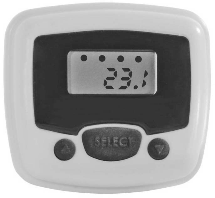
4 SPECIFICATIONS / DIMENSIONS Display type: LCD, 6 digit with 4 relay indicators Display units: Engineering units, liquid volume or height Display output: to Character height: 0.374" (9.5 mm) Decimal point: Fixed Dot indication: Relay status User interface: Three button Sensor input: Any LVCN 414, LVCN 210 & LVCN 318 Series sensor Step Two Supply voltage: Provided by the level sensor Operating temp.: F: 4 to 140 C: 20 to 60 Cable type: 4 conductor, #22 AWG Cable length: 4' (1.2m) Cable material: Polyurethane Enclosure rating: NEMA 4 (IP65) when mounted Enclosure mat l: Polycarbonate Enclosure type: Panel mount Button mat l: Silicon rubber Compliance: CE, RoHS Dimensions Included Components LVCN 40 Series comes with a 4 (1.2m) cable, locking nut and the Manual. LVCN 40 Series Front View LVCN 40 Series Side View 4
5 SAFETY PRECAUTIONS Step Three About this Manual: PLEASE READ THE ENTIRE MANUAL PRIOR TO INSTALLING OR USING THIS PRODUCT. This manual includes information on the LVCN 40 Series level indicator from OMEGA ENGINEERING. Please refer to the part number located on the switch label to verify the exact model configuration, which you have purchased. User s Responsibility for Safety: OMEGA ENGINEERING manufactures a broad range of level sensing technologies. While each of these sensors is designed to operate in a wide variety of applications, it is the user s responsibility to select a sensor model that is appropriate for the application, install it properly, perform tests of the installed system, and maintain all components. The failure to do so could result in property damage or serious injury. Proper Installation and Handling: Only professional staff should install and/or repair this product. Install the level indicator with the included locking nut and never over tighten the indicator within the installation. Always check for leaks prior to system start up. Wiring and Electrical: A supply voltage of 12 to 28 VDC is used to power the LVCN 40 Series and the LVCN 414, LVCN 210 & LVCN 318 Series sensor. Electrical wiring of the transmitter should be performed in accordance with all applicable national, state, and local codes. Material Compatibility: The enclosure is made of Polycarbonate (PC) with the Cable made of Polyurethane and the Buttons made of silicon rubber. Make sure that the model, which you have selected, is chemically compatible with the application media. Enclosure: While the level indicator housing is liquid resistant the LVCN 40 Series is not designed to be operational when immersed. It should be mounted in such a way that the enclosure and level indicator do not come into contact with the application media under normal operational conditions. Make a Fail Safe System: Design a fail safe system that accommodates the possibility of LVCN 414, LVCN 210 & LVCN 318 Series/LVCN 40 Series and/or power failure. OMEGA ENGINEERING recommends the use of redundant backup systems and alarms in addition to the primary system. Flammable, Explosive or Hazardous Applications: LVCN 40 Series should not be used within classified hazardous environments. Safety Installation should be done by properly trained staff Supply voltage should never exceed a maximum of 28 VDC Make sure the sensor is chemically compatible with your application Design a fail safe system that accommodates the possibility of sensor and/or power failure This sensor should not be used in classified hazardous environments 5

6 GETTING STARTED Step Four LVCN 40 Series does not require any configuration. LVCN 40 Series level indicator will automatically read the configuration of the attached LVCN 414, LVCN 210 & LVCN 318 Series sensor and display the level per the sensor s configuration. The sensor does require configuration with the LVCN 414 SW 6.0 software (especially if any relays are to be used). For a copy of the LVCN 414 SW 6.0 software, please go to click on the Flow, Level, ph, Environmental, and Pressure Section, select Products and then click on the LVCN414 folder. Before attaching LVCN 40 Series to any sensor, configure the LVCN 414, LVCN 210 & LVCN 318 Series sensor to LVCN 414 SW 6.0 software via the Fob. Once the sensor is configured, remove the Fob and attach the LVCN 40 Series. Note: Please refer to LVCN 414, LVCN 210 & LVCN 318 Series manual for the wiring, configuration with the LVCN 414 SW 6.0 software and installation of the sensor. 6
.")
7 WIRING Step Five Wiring LVCN 40 Series to any LVCN 414, LVCN 210 & LVCN 318 Series Sensor: LVCN 40 Series and associated level sensor require a 12 to 28 VDC power supply to operate. The maximum cable distance between LVCN 40 Series and the sensor is 15 (4.5m). Follow the below steps to wire LVCN 40 series with the sensor: LVCN 40 Series Sensor Wiring identical for all series of LVCN 414, LVCN 210 & LVCN 318 Series Sensors. Use only the Red, Black, Green and White wires. 1. Connect the Red and Black wires of both LVCN 40 Series and the sensor to the VDC power supply. 2. Connect the Green and White wires of LVCN 40 Series to the corresponding Green and White wires of the sensor. 3. Isolate the Green and White wires from active power to prevent a short of the configuration circuit. Adding a Loop Powered Display General Safety Where personal safety or significant property damage can occur due to a spill, the application must have a redundant backup safety system installed. Wiring should always be done by a licensed electrician. Supply voltage should never exceed 28 VDC. Protect the sensor from electrical spikes by isolating the power. Design a fail safe system for possible indicator and/or power failure. Never use the sensor in environments classified as Hazardous. 7


8 UNDERSTANDING LVCN 40 SERIES Step Six Level Height vs. Volume: The latest version of LVCN 414 SW 6.0 software has a new feature which allows the sensor to be configured to read either the height of the liquid or the volume of the liquid. This selection is made under the Sensor Output Units selection of either Volume (volume of liquid) or Distance (height of liquid). See the chart below for the engineering unit options available for both Distance and Volume. Units of Measurement Distance Volume Inches Gallons Cm Liters Feet Meters There are 6 different tank shapes that you can select with LVCN 414 SW 6.0 Software. Vertical Cylinder Tank Vertical Cylinder Tank with Cone Bottom Rectangular Tank Horizontal Cylinder Tank with End Caps Horizontal Cylinder Tank with Spherical End Caps Spherical Tank 8
 will always provide a linear output, regardless of selecting Distance or Volume.")

9 UNDERSTANDING LVCN 40 SERIES Step Six Linear vs. Non Linear: Two of the shapes (Vertical Cylinder Tank and Rectangular Tank) will always provide a linear output, regardless of selecting Distance or Volume. The remaining four shapes (Vertical Cylinder Tank with Cone Bottom, Horizontal Cylinder Tank with End Caps, Horizontal Cylinder Tank with Spherical End Caps and Spherical Tank) will have a linear output when Distance is selected, but will have a non linear output when volume is selected. Vertical Cylindrical Tank Horizontal Cylinder Tank with End Caps In the above illustration, 10 of liquid will always be equal to 100 gallons of liquid (1 = 10 gallons). In the above illustration, 10 of liquid does not equal 100 gallons. The 10 at the bottom represents a rise of 62.8 gallons where the change between 10 and 20 represents an increase of gallons. When volume is selected, the 4 20 ma output from the sensor will be proportional to the volume of the tank, not the height of the tank. This means that the current output will track the volume of the tank (in gallons or liters) within a non linear tank (Vertical Cylinder Tank with Cone Bottom, Horizontal Cylinder Tank with End Caps, Horizontal Cylinder Tank with Spherical End Caps or Spherical Tank). When connecting the 4 20 ma output to a display, the current signal will follow the volume of the tank. The display will also reflect the volume of the tank and not the height of the liquid. Example #1 (Volume Output): In the illustrations 20 of liquid, the display will show gallons in the Vertical Cylindrical Tank. However, in the Horizontal Cylinder Tank with End Caps, the same level of 20 would show gallons. 9
10 UNDERSTANDING LVCN 40 SERIES Step Six Example #2 (Current Output): in the illustrations below, the 4mA signal is set at 0 (0.0 gallons) and the 20 ma signal is set to 60 (600.0 gallons). In the Vertical Cylindrical Tank, 40 of liquid will output a current signal of 14.67mA. However, in the Horizontal Cylindrical Tank with End Caps, 40 of liquid will output a current signal of 15.41mA. A simple loop display set with 4mA = 0 gallons and 20 ma = 600 gallons will show two different volumes based upon the tank shape configuration. Vertical Cylindrical Tank will show gallons while Horizontal Cylindrical Tank with End Caps will show gallons. Vertical Cylindrical Tank Horizontal Cylinder Tank with End Caps 10 of liquid will always be equal to 100 gallons of liquid (1 = 10 gallons). 1 of liquid does not equal 10 gallons. The 10 at the bottom represents a rise of 62.8 gallons where the change between 10 and 20 represents an increase of gallons. 10


11 UNDERSTANDING LVCN 40 SERIES Step Six Relay Settings: LVCN 40 Series not only displays the level reading of the LVCN 414, LVCN 210 & LVCN 318 Series sensor (Height or Volume), but LVCN 40 Series also allows you to adjust the settings for relays. LVCN 40 Series will not allow changes to Sensor Height or Fill Height, just the relay settings. The sensor configured to read inches of liquid plus 4 high alarm relays. The sensor configured to read inches of liquid plus duplex relays and high and low alarm relays. The sensor configured to read gallons of liquid plus 2 high alarm and 2 low relays. The sensor configured to read gallons of liquid plus an auto empty relays and high and low alarm relays. 11
.")
12 INSTALLATION Step Seven LVCN 40 Series is designed for typical panel mount installations, either located within an instrument panel or through the wall of a NEMA box enclosure. Panel Mount: The maximum cable distance between LVCN 40 Series and LVCN 414, LVCN 210 & LVCN 318 Series sensor is 15 (4.5m). Follow the below steps to install the indicator in a panel or NEMA box enclosure located near the sensor: 1. Drill (1) large 0.75 (19.1mm) diameter hole in the panel for the cable and nipple. 2. Drill (1) small 0.25 (6.4mm) diameter hole 0.83 (21.1mm) below the large hole that will prevent the installed indicator from rotating off center. 3. Run the indicator cable through the large top hole and locking nut (on the rear side of the panel). 4. Properly align the indicator with the flat gasket and holes on the panel. Then press the indicator in place against the panel. 5. Tighten the locking nut down over the nipple and route the cable for termination. 12
. Relay 1 4 Indicates when the sensor s relay is energized.")
 or the volume of liquid (gallons or liters). o The selection of height vs. volume is set in the LVCN 414 SW 6.0 software.")

13 GETTING AROUND LVCN 40 SERIES Step Eight LVCN 40 Series features a 6 digit display with relay indicators and a three button user interface. The indicator displays the measured value and relay status of the connected sensor (if the sensor has relays and they are configured for use). Relay 1 4 Indicates when the sensor s relay is energized. Note: Not all LVCN 414 series sensor models have relays. o If the sensor does not have any relays, then the indicators will remain off. 6 digit Display Shows the liquid level in height (inches, cm, feet or meters) or the volume of liquid (gallons or liters). o The selection of height vs. volume is set in the LVCN 414 SW 6.0 software. Up Button Used to increase a set point value. Select Button Used to enter the Menu and accept values. Down Button Used to decrease a set point value. Note: To increase the scrolling speed of the display, hold down the SELECT button while simultaneously pressing the UP or DOWN button. Entering the MENU: If desired, users can change the sensor s relay ALARM, VALVE or PUMP ON OFF set points using LVCN 40 Series. To enter the menu LVCN 40 Series MENU functions, press and hold the SELECT button for 5 seconds. The MENU will then scroll between the configured PUMP, ALAMRS and RUN modes. Note: If the relays are configured for PUMPS and ALARMS, then both will appear in the menu. If the relays are configured for Alarms only, then PUMP will not appear. If the relays are configured for PUMPS only (also for valves), then ALARMS will not appear. To change a pump set point value, press SELECT when PUMP appears. To change an Alarm set point value, press SELECT when ALARMS appear. To exit the menu and return to run mode, press SELECT when RUN appears. 13
 relay is configured for pump or valve control. Simplex pump control has (1) ON and (1) OFF setting.")
 LAG, (1) ON and (1) OFF set point.")
 you want to change appears. 4.")
14 GETTING AROUND LVCN 40 SERIES Step Eight Changing a Pump Set Point: Sensors (LVCN 414, LVCN 210 & LVCN 318 Series) with relays have (1 4) channels active on the LVCN 40 Series. If after accessing the MENU, PUMP appears in the display, then at least (1) relay is configured for pump or valve control. Simplex pump control has (1) ON and (1) OFF setting. Duplex pump control (2 pumps) has a third additional LAG setting. Note: Prior to making any changes, we recommend that you write down all existing set point values. The example below highlights a duplex pump system in an automatic empty or automatic fill operation with (1) LAG, (1) ON and (1) OFF set point. Use the following steps to change your simplex or duplex pump control settings. Automatic Empty Operation Automatic Fill Operation Steps to Change Pump Set Points 1. Hold SELECT for 5 seconds to enter the MENU. 2. Press SELECT when PUMP appears. 3. Press SELECT when the set point (ON, OFF, LAG) you want to change appears. 4. Press the UP and DOWN buttons to increase or decrease the set point to the desired value. To scroll faster, hold SELECT while pressing UP or DOWN. 5. To enter the set point, hold SELECT for 2 seconds. 6. To change another set point, press SELECT when the set point appears. 7. To exit the MENU, press SELECT when RUN appears. Tech Tips Never place a relay set point (ON, OFF, LAG) at the liquid empty or liquid full position. You should have at least some distance or volume buffer separating them. For example, in a 500 gallon tank, the relay set points could be placed at 10 gallons or 490 gallons. 14
 relay is configured as an alarm.")
15 GETTING AROUND LVCN 40 SERIES Step Eight Changing an Alarm Set Point: Sensors (LVCN 414, LVCN 210 & LVCN 318 Series) with relays have (1 4) channels active on the LVCN 40 Series. If after accessing the MENU, ALARMS appears in the display, then at least (1) relay is configured as an alarm. The Alarm settings may be in any combination of LOW and/or HIGH alarms (4 HIGH, 1 LOW & 3 HIGH, 2 LOW & 2 HIGH, etc.). Note: Prior to making any changes, we recommend that you write down all existing set point values. The example below highlights a 2 LOW and 2 HIGH alarm operation with (4) set points. Use the following steps to change your alarm settings. Steps to change Alarm settings: 1. Hold SELECT for 5 seconds to enter the MENU. 2. Press SELECT when ALARMS appears. 3. Press SELECT when the set point (HIGH2, HIGH 1, LOW1, LOW2) you want to change appears. 4. Press the UP and DOWN buttons to increase or decrease the set point to the desired value. To scroll faster, hold SELECT while pressing UP or DOWN. 5. To enter the set point, hold SELECT for 2 seconds. 6. To change another set point, press SELECT when the set point appears. 7. To exit the MENU, press SELECT when RUN appears. Hints: Never place a relays set point (High 1, Low 1) at the liquid empty or liquid full position. You should have at least some distance or volume buffer separating them. For example, in a 500 gallon tank, the relay set points could be placed at 10 gallons or 490 gallons. 15
16 TROUBLESHOOTING Step Nine Display Descriptors: The following are the display s operational descriptors, meaning and corrective action: WARMUP MENU PUMP OFF ON LAG ALARM HIGH # LOW # CHECK WIRES UPDATE FW REV WARMUP is seen when power is first applied to the sensor and LVCN 40 Series. WARMUP indicates that the display is waiting for the sensor to acquire and send a valid level reading. Indicates the menu for configuration of relay set points. PUMP is the identifier for the relay set points affecting Pump or Valve operations. OFF is the relay set point that turns OFF the pump. ON is the relay set point that turns ON the pump. LAG is the set point that turns ON the lag pump. Alarm is the identifier for the relay set points affecting Alarm operations. HIGH # is the relay set point that energizes a high alarm relay. LOW # is the relay set point that energizes a low alarm relay. Not All four wires are properly connected to the sensor. Check the wiring between the LVCN 40 Series and the level sensor. The attached sensor is not running a version of the firmware (50.0 or higher) that is compatible with LVCN 40 Series. Connect the LVCN 414, LVCN 210 or LVCN 318 Series to the LVCN 414 SW 6.0 software and update the firmware. 16
17 17
18 18


19 19


20 20
INTRODUCTION / TABLE OF CONTENTS
 1 2 INTRODUCTION / TABLE OF CONTENTS Step One The small tank sensor is an innovative level sensor family that replaces float, conductance and pressure sensors that fail due to contact with dirty, sticking
INSTALLATION INSTRUCTIONS
 LIGHTING CONTROL PANELS 4 AND 8 RELAYS INSTALLATION INSTRUCTIONS INSTALLATION OVERVIEW The installation instructions contained in this document are provided as a guide for proper and reliable installation.
OPL BASIC. Dosing System for Professional Laundry machines. Contents
 OPL BASIC Dosing System for Professional Laundry machines Contents 1 Getting Started. Page 2 2 Installation. Page 4 3 Set Up & Operation. Page 8 4 Maintenance & Accessories. Page 10 5 Troubleshooting Page
Fire Pump Controllers Remote Alarm Panels
 Fire Pump Controllers Remote Alarm Panels Remote Alarm Panels 1.8 Remote Alarm Panels FDAP-M Electric... DFDAP-M Diesel... Product Specifications... 2 6 9 Features 1-1 DFDAP-M / FDAP-M Remote Alarm Panel
NOTE: It is the responsibility of the installation organization to have only technically qualified personnel performing the installation.
 This quick start guide provides, basic installation information, drawings, first time power-on instructions, and short descriptions of key terms and concepts for installing the EntraGuard Platinum Telephone
12 Volt 30 Amp Digital Solar Charge Controller
 12 Volt 30 Amp Digital Solar Charge Controller User s Manual WARNING Read carefully and understand all INSTRUCTIONS before operating. Failure to follow the safety rules and other basic safety precautions
TC-9102 Series Surface Mount Temperature Controllers
 TC-9102 Series Surface Mount Temperature Controllers General Description & Applications The TC-9102 Series Temperature Controller offers a versatile solution for a wide variety of applications that may
HM-W536 Install Guide
 HM-W536 Install Guide 9/13/2013 IMPORTANT SAFETY INSTRUCTIONS Warning - When using electrical devices, basic safety precautions should be followed to reduce the risk of fire, electrical shock or injury.
P R O D U C T S P E C I F I C A T I O N MSA Ultima X Series Sensor/Transmitter Specification
 P R O D U C T S P E C I F I C A T I O N MSA Ultima X Series Sensor/Transmitter Specification 1.0 This specification details the attributes and operating characteristics of the MSA Ultima X Series sensors/transmitters.
RI-215A Operator s Manual. Part Number: 71-0045RK Revision 0 Released: 10/3/05
 RI-215A Operator s Manual Part Number: 71-0045RK Revision 0 Released: 10/3/05 Warranty RKI Instruments, Inc., warrants gas alarm equipment sold by us to be free from defects in materials and workmanship,
* DISCLAIMER: Contents. How to Use This Guide: COMMERCIAL INSTALL GUIDE 2
 COMMERCIAL INSTALL GUIDE 2 Contents How to Use This Guide: The first section of this guide is designed to assist you with the installation of your DECK Monitoring hardware. The revenue grade meter and
IntelliBrite Controller (For IntelliBrite Pool, Spa and Landscape Lighting Fixtures) Installation and User s Guide
 Installation and User s Guide") IntelliBrite Controller (For IntelliBrite Pool, Spa and Landscape Lighting Fixtures) Installation and User s Guide *619751* P/N 619751 - Rev C IMPORTANT SAFETY INSTRUCTIONS READ AND FOLLOW ALL INSTRUCTIONS
IntelliBrite Controller (For IntelliBrite Pool, Spa and Landscape Lighting Fixtures) Installation and User s Guide *619751* P/N 619751 - Rev C IMPORTANT SAFETY INSTRUCTIONS READ AND FOLLOW ALL INSTRUCTIONS
PowerLogic Sub Meter Display (SMD and SMDOPN)
") Instruction Bulletin Z203742-0B PowerLogic Sub Display (SMD and SMDOPN) CONTENTS Introduction... 2 Parts of the Sub Display... 3 Dimensional Drawing... 4 Installation... 5 Mounting the SMD... 5 Mounting
Instruction Bulletin Z203742-0B PowerLogic Sub Display (SMD and SMDOPN) CONTENTS Introduction... 2 Parts of the Sub Display... 3 Dimensional Drawing... 4 Installation... 5 Mounting the SMD... 5 Mounting
Installation. Smart-UPS VT MGE Galaxy 3500. Maintenance Bypass Panel. 10-40 kva 400 V
 Installation Smart-UPS VT MGE Galaxy 3500 Maintenance Bypass Panel 10-40 kva 400 V Contents Safety.................................................. 1 Save these instructions...................................
TMS TANK MANAGEMENT SYSTEM
 TMS TANK MANAGEMENT SYSTEM Page 1 of 9 Operating Instructions GENERAL The Tank Management System is a bespoke design to control, monitor and accommodate efficient storage and dispensing of TMS. FUNCTIONS
OEM Manual MODEL 2350 ELECTRONIC DUAL CYLINDER SCALE
 OEM Manual MODEL 2350 ELECTRONIC DUAL CYLINDER SCALE Scaletron Industries, Ltd. Bedminster Industrial Park 53 Apple Tree Lane P.O. Box 365 Plumsteadville, PA 18949 USA Toll Free: 1-800-257-5911 (USA &
5-port / 8-port 10/100BaseTX Industrial Ethernet Switch User Manual
 5-port / 8-port 10/100BaseTX Industrial Ethernet Switch User Manual Content Overview... 1 Introduction... 1 Features... 3 Packing List... 4 Safety Precaution... 4 Hardware Description... 5 Front Panel...
Applied Electronics. Commercial Dimming System UPDATE NOTICE
 REV. A Applied Electronics Commercial Dimming System UPDATE NOTICE This notice is to inform the end user of an additional feature added to this DP12/2400 dimming unit. This unit has been outfitted with
PART 1 - INTRODUCTION...
 Table of Contents PART 1 - INTRODUCTION... 3 1.1 General... 3 1.2 Sensor Features... 3 1.3 Sensor Specifications (CDE-45P)... 4 Figure 1-1 CDE-45P Sensor Dimensions (standard, convertible style)... 4 PART
Toroidal Conductivity Sensor
 Instruction Sheet PN 51A-/rev.C June 2012 Toroidal Conductivity Sensor For additional information, please visit our website at www.emersonprocess.com/rosemountanalytical.com SPECIFICATIONS Wetted Materials:
DREXELBROOK. USonic-R Series. Ultrasonic Level Measurement System. User Friendly
 DREXELBROOK A Leader In Level Measurement Solutions USonic-R Series Ultrasonic Level Measurement System User Friendly Set the measurement range directly in inches, feet, millimeters, centimeters, or meters
Introduction. Safety Guidelines. Part Numbers. Operation and Maintenance Manual. Operation and Maintenance Manual
 Operation and Maintenance Manual Introduction Read all instructions thoroughly. Installation of the OilTector must comply with all Federal, State and Local Codes, Regulations and Practices. The OilTector
Model 201 Wiegand Touchpad Reader Installation Guide
 Model 201 Wiegand Touchpad Reader Installation Guide P/N 460353001C 15AUG11 2011 UTC Fire & Security. All rights reserved. This document may not be copied in whole or in part or otherwise reproduced without
Power Supply and Indicator Unit Type 5024-1. Fig. 1 Type 5024-1. Mounting and Operating Instructions EB 9539 EN
 Power Supply and Indicator Unit Type 5024-1 Fig. 1 Type 5024-1 Mounting and Operating Instructions EB 9539 EN Edition October 2003 Application 1 Application The Type 5024-1 Power Supply and Indicator Unit
PS4-24 OWNERS MANUAL 24 VAC 90 WATT WALL MOUNTED CCTV POWER SUPPLY
 PS4-24 OWNERS MANUAL 24 VAC 90 WATT WALL MOUNTED CCTV POWER SUPPLY 7320 Ashcroft, Suite 104 Houston, Texas 77081 p: 713-772-1404 f: 713-772-7360 e: info@juicegoose.com www.juicegoose.com 06-06 CONGRATULATIONS
Advantium 2 Plus Alarm
 ADI 9510-B Advantium 2 Plus Alarm INSTALLATION AND OPERATING INSTRUCTIONS Carefully Read These Instructions Before Operating Carefully Read These Controls Corporation of America 1501 Harpers Road Virginia
DTM04 TANK MONITOR DTM08 TANK MONITOR Dtm12 TANK MONITOR. Installation and Operation Manual
 DTM04 TANK MONITOR DTM08 TANK MONITOR Dtm12 TANK MONITOR Installation and Operation Manual 1 ENGLISH Safety Instructions 2 Features 2-3 Specifications 3 Installation 4-5 Wiring Diagrams 6-7 Warranty 8
Automatic Transfer Switch FT-10 Network Control Communications Module (CCM-T) Kit 541 0811
 Kit 541 0811") Instruction Sheet 1-2003 Automatic Transfer Switch FT-10 Network Control Communications Module (CCM-T) Kit 541 0811 PURPOSE OF KIT A CCM-T is used to monitor and control an automatic transfer switch. The
Instruction Sheet 1-2003 Automatic Transfer Switch FT-10 Network Control Communications Module (CCM-T) Kit 541 0811 PURPOSE OF KIT A CCM-T is used to monitor and control an automatic transfer switch. The
Part Name/Description Part Number Quantity. Power Cable 4000950-5 1
 Note: Indented items indicate parts included in an assembly listed above Part Name/Description Part Number Quantity Power Cable 4000950-5 1 Raven Harness Adapter Kit 4100525 1 Installation Instructions
Series 510 Submersible Level Transmitters
 Series 510 Submersible Level Transmitters The Series 510 Submersible Level Transmitters are solid state instruments designed for direct submergence into many types of liquid for quick, accurate and reliable
INSTALLATION AND OPERATING INSTRUCTIONS For Model GL1 Gate Locks
 Securitron Magnalock Corp. www.securitron.com ASSA ABLOY, the global leader Tel 800.624.5625 techsupport@securitron.com in door opening solutions INSTALLATION AND OPERATING INSTRUCTIONS For Model GL1 Gate
Series DFMT Digital Paddlewheel Flowmeter
 Series DFMT Digital Paddlewheel Flowmeter Bulletin F-DFMT Specifications - Installation Operating Instructions -/8 [00] -/ [8] -/8 [00] A The Series DFMT Digital Paddlewheel Flow Transmitter provides instantaneous
Solid Core and Split Core Adjustable Current Status Switches CSS-O, CSS-C; CSP-O, CSP-C
 Solid Core and Split Core Adjustable Current Status Switches CSS-O, CSS-C; CSP-O, CSP-C DESCRIPTION FEATURES PRODUCT DATA Very low operating trip points LED status indication Integral DIN rail mounting
GSM Autodialer Professional GJD700 Speech & Text Autodialer
 Text Edit message GSM Autodialer Professional GJD700 Speech & Text Autodialer Introduction The GSM Autodialer Professional works in conjunction with standard alarm systems and makes use of your preferred
Manual for Fire Suppression & Methane Detection System
 Manual for Fire Suppression & Methane Detection System Fogmaker North America Post address: 150 Gordon Dr Exton, PA 19341 Delivery address: 150 Gordon Dr Exton, PA 19341 Tel: 610-265-3610 Fax: 610-265-8327
SPY-BATT Battery Tutor Device Installation Manual Rev. 1.1-07/04/2016
 SPY-BATT Battery Tutor Device Installation Manual Rev. 1.1-07/04/2016 1. GENERAL DESCRIPTION The SPY-BATT is a device that allows to monitor the state of your battery. The SPY-BATT stores over time the
PARAGON ELECTRIC, INC. LIQUID LEVEL CONTROLLER USER MANUAL MODELS: LLC-I, LLC-II AND TELEMETRY OPTIONS
 PARAGON ELECTRIC, INC. LIQUID LEVEL CONTROLLER USER MANUAL MODELS: LLC-I, LLC-II AND TELEMETRY OPTIONS 2 Table of Contents Safety... 4 Introduction... 5 Features and Benefits... 6 Control Overview... 7
GROENEVELD AUTOMATIC GREASING SYSTEMS
 GROENEVELD AUTOMATIC GREASING SYSTEMS TWIN Parts & Accessories Book Pumps, Fittings, Injectors, Lining, etc. www.groeneveld-group.com 1 TWIN ELECTRICAL Item Part # Description 1 F113966 Switch 24V 2 F122991
98371000 REV. REL 1302 WEST BEARDSLEY AVENUE P.O. BOX 1127 ELKHART IN 46515 (574) 295-8330 FAX (574) 293-9914 2011 ELKHART BRASS MFG. CO., INC.
 295-8330 FAX (574) 293-9914 2011 ELKHART BRASS MFG. CO., INC.") 81471067 Electric Monitor Motor Control Panel For use with Model 8394059 SPIT-FIRE Monitor Installation, Operation, and Maintenance Instructions FOR ATEX APPLICATIONS 1302 WEST BEARDSLEY AVENUE P.O. BOX
81471067 Electric Monitor Motor Control Panel For use with Model 8394059 SPIT-FIRE Monitor Installation, Operation, and Maintenance Instructions FOR ATEX APPLICATIONS 1302 WEST BEARDSLEY AVENUE P.O. BOX
www.sebury.com.cn Digital Keypad Use s Manual
 K3 K4 www.sebury.com.cn Digital Keypad Use s Manual Contents Introduction Introduction Specifications Intramural Interface Circuit 3 Mounting 3 Wiring 5 Power UP 7 Engineer Programming Mode 7 The K3/K4
FAQ s on Siemens Magmeters
 FAQ s on Siemens Magmeters 1. The cables for the coils and electrodes for the magmeters look the same. Does it matter which cable is used for coils and which one is used for the electrodes? Both cables
DORMA MODEL PS-406BB POWER SUPPLY INSTALLATION INSTRUCTIONS
 Features: INSTALLATION Install in accordance with NFPA 70. DORMA MODEL PS-406BB POWER SUPPLY INSTALLATION INSTRUCTIONS Up to 1.95 Amps Load Capacity Class 2 Rated Outputs Overload, Over Voltage, and Short
Troubleshooting and Diagnostics
 Troubleshooting and Diagnostics The troubleshooting and diagnostics guide provides instructions to assist in tracking down the source of many basic controller installation problems. If there is a problem
INSTALLATION & SERVICE MANUAL. Display Panel
 INSTALLATION & SERVICE MANUAL Display Panel The PowerLine EMS TM is a specialized power distribution and energy management system intended to be used in recreational vehicles. The Control Module is housed
T0118 T2118 T3118. Instruction Manual
 Programmable indoor transmitter of temperature T0118 Programmable indoor transmitter of atmospheric pressure T2118 Programmable indoor transmitter of temperature, relative humidity and other derived humidity
Streaming Potential System (SPT1000, SPD1000)
") Streaming Potential System (SPT1000, SPD1000) User's Manual Sentrol Systems, Inc. 3949 Cotswold Dr. SW, Lilburn, GA 30047-2371 Tel: 770-564-1541, Fax: 770-564-8605 www.sentrolsystems.com Since the streaming
Streaming Potential System (SPT1000, SPD1000) User's Manual Sentrol Systems, Inc. 3949 Cotswold Dr. SW, Lilburn, GA 30047-2371 Tel: 770-564-1541, Fax: 770-564-8605 www.sentrolsystems.com Since the streaming
SECTION G2: CABLE PROCESSOR MODULE MAINTENANCE
 SECTION G2: CABLE PROCESSOR MODULE MAINTENANCE Cable Processor Module overview WARNING! When tipping the Cable Processor Module back, (after removing the toggle arm pin), use extreme caution not to drop
FIRERAY 2000 Installation Guide
 FIRERAY 2000 Installation Guide Features Range 33ft to 330 ft. 24Vdc operation Selectable alarm thresholds Low current consumption Ground level electronics Manual or Automatic reset System Description
LDG DTS-4/4R Desktop Coaxial Switch / Remote
 LDG DTS-4/4R Desktop Coaxial Switch / Remote LDG Electronics 1445 Parran Road, PO Box 48 St. Leonard MD 20685-2903 USA Phone: 410-586-2177 Fax: 410-586-8475 ldg@ldgelectronics.com www.ldgelectronics.com
SYSTEM 4C. C R H Electronics Design
 SYSTEM 4C C R H Electronics Design SYSTEM 4C All in one modular 4 axis CNC drive board By C R Harding Specifications Main PCB & Input PCB Available with up to 4 Axis X, Y, Z, A outputs. Independent 25
ELITE-L Series. ELITE - Low Voltage / Dry contact Remote Control System
 ELITE-L Series ELITE - Low Voltage / Dry contact Remote Control System Applications Garden Lighting Pond pumps Remote outdoor Switching Access control Industrial control Features 4 switched channels 1000W
CONNECTOR AMPLIFIER FOR PROPORTIONAL VALVES (4-20 ma Input Version)
") TECHNICAL DATASHEET #TD1102AX CONNECTOR AMPLIFIER FOR PROPORTIONAL VALVES (4-20 ma Input Version) Part Number: Connector Amplifier CAPV-H-4-20MA-x complete with cable CAPV-4C-yM Where: x = current output
TECHNICAL DATASHEET #TD1102AX CONNECTOR AMPLIFIER FOR PROPORTIONAL VALVES (4-20 ma Input Version) Part Number: Connector Amplifier CAPV-H-4-20MA-x complete with cable CAPV-4C-yM Where: x = current output
WIND ALARM. Wind Speed Alarm. Wind Speed. Set Point 2. Set Point 1 NEW BEDFORD, MA 02745 USA
 Thank you for purchasing the Maximum wind speed alarm. The Maximum wind speed alarm is a dual set point wind speed indicator with a two digit LED display. It contains a yellow light to display one set
OEM-EP Pressure Controllers
 Pressure Controllers Typical Applications Carrier Gas Pressure Control Air over Liquid Control Mass Spectrometer Process Gas Supply Pressure Control Miniature ler The Miniature ler converts a variable
Outdoor 33.6W Dual Port Passive Power-over-Ethernet Midspan For External Security Cameras and Wireless Access Points
 Outdoor 33.6W Dual Port Passive Power-over-Ethernet Midspan For External Security Cameras and Wireless Access Points Features SELV Compliant No Detection Passive Injector Gigabit Compatible Full Protection
Troubleshooting Guide for Jacks Down LED Lights
 Troubleshooting Guide for Jacks Down LED Lights Equalizer Systems Auto-Level systems manufactured after 2005 feature a pressure switch system that monitors the retracted state of leveling jacks and any
PLC Control Unit for a CSM-C Steam Compact Clean Steam Generator
 3.635.5275.251 IM-P486-19 CH Issue 2 PLC Control Unit for a CSM-C Steam Compact Clean Steam Generator Installation, Start-up and Operation Manual 1. Safety information 2. General product information 3.
Fiber Optic Selector Guide for Analog & Digital Data Links, Contact Closures & Multiplexers
 Fiber Optic Selector Guide for Analog & Digital Data Links, Contact Closures & Multiplexers Analog Data Links Multi-Channel Contact Closures Multiplexers Digital Data Links - Contact Closures Power Supply
Recommended Product Specifications Fuel Day Tank System Tramont UTRS Fuel Day Tank
 Recommended Product Specifications Fuel Day Tank System Tramont UTRS Fuel Day Tank This specification describes requirements for a Diesel Fuel Day Tank System consisting of one or more fuel tanks, an Electronic
12 Volt 30 Amp Digital Solar Charge Controller Installation & Operation Manual
 12 Volt 30 Amp Digital Solar Charge Controller Installation & Operation Manual This 30Amp charge controller is designed to protect your 12Volt Lead-acid or Gel-cell battery from being overcharge by solar
Shunt lock function 3066
 Version: January 2004 Contents Alarm System Activation unit Deactivation unit Digital locking cylinder or Smart Relay 1.0 Method of Operation 4 1.1 General 4 1.2 Turning the Alarm System On 4 1.3 Turning
WATER LEAK DETECTION SYSTEM WLDS-10 INSTALLATION & COMMISSIONING
 WATER LEAK DETECTION SYSTEM WLDS-10 INSTALLATION & COMMISSIONING DESCRIPTION: An electronic control panel used in conjunction with one pulse meter (water meter with pulse output proportional to flow rate)
TSn SERIES Surge Protective Device
 Page: 1 of 8 TSn SERIES Surge Protective Installation & Operation Manual 3621 Saunders Avenue www.systems.us Ph 804.355.1100 Richmond, VA 23227 4354 Sales@Systems.us Fax 804.355.8900 Page: 2 of 8 Quick
IPX AUTOMATIC IP NETWORK LOSS BACKUP A/B SWITCH INSTRUCTION BOOK IB6444-02
 IPX AUTOMATIC IP NETWORK LOSS BACKUP A/B SWITCH INSTRUCTION BOOK IB6444-02 TABLE OF CONTENTS DESCRIPTION 2 MOUNTING INSTRUCTIONS 2 HOW TO CABLE THE IPX 2/3 POWER SUPPLY INSTALLATION 3 OPERATION 3 CARE
Standard Buccaneer - USB
 IP68 rated USB version 2.0 performance Plug and play capability Visual mating indication Shielded system Single and double ended cables Screw coupling PCB versions Dust and waterproof sealing when mated
Transmitter Interface Program
 Transmitter Interface Program Operational Manual Version 3.0.4 1 Overview The transmitter interface software allows you to adjust configuration settings of your Max solid state transmitters. The following
Detector transparent with Color Inserts. FAA 500 TR P Trim Ring transparent with Color Inserts. FCA 500 / FCA 500 E Detector Bases
 Detector Color Detector transparent with Color Inserts FAA 500 TR W Trim Ring FAA 500 TR P Trim Ring transparent with Color Inserts FAA 500 BB Ceiling Mount Back Box FCA 500 / FCA 500 E Detector Bases
Firmware version: 1.10 Issue: 7 AUTODIALER GD30.2. Instruction Manual
 Firmware version: 1.10 Issue: 7 AUTODIALER GD30.2 Instruction Manual Firmware version: 2.0.1 Issue: 0.6 Version of the GPRS transmitters configurator: 1.3.6.3 Date of issue: 07.03.2012 TABLE OF CONTENTS
Contents. Document information
 User Manual Contents Document information... 2 Introduction... 3 Warnings... 3 Manufacturer... 3 Description... Installation... Configuration... Troubleshooting...11 Technical data...12 Device Scope: PCB
AMERBRITE UNDERWATER WHITE LED POOL LAMP
 AMERBRITE UNDERWATER WHITE LED POOL LAMP FOR USE ONLY WITH PENTAIR AMERLITE LUMINAIRE INSTALLATION AND USER S GUIDE IMPORTANT SAFETY INSTRUCTIONS READ AND FOLLOW ALL INSTRUCTIONS SAVE THESE INSTRUCTIONS
ETC TWO STAGE ELECTRONIC TEMPERATURE CONTROL
 RANCO INSTALLATION INSTRUCTIONS ETC TWO STAGE ELECTRONIC TEMPERATURE CONTROL Relay Electrical Ratings PRODUCT DESCRIPTION The Ranco ETC is a microprocessor-based family of electronic temperature controls,
HMI display Installation Guide
 HMI display Installation Guide Product Description Specifications Important Information o Package Contents o Related Documents o Accessories Cautions and Warnings Mounting and Dimensions o BAC-DIS-ENC
MEDIUM FLAT PANEL DISPLAY STATIC MOUNT MSR Series
 INSTALLATION INSTRUCTIONS MEDIUM FLAT PANEL DISPLAY STATIC MOUNT The static mount accommodates medium flat panel displays weighing up to 125 lbs (57 kgs). The teardrop holes in the mount allow for quick
Sanitary Type Electronic Flow Switches
 Industries Pharmaceutical Sanitary Type Electronic Flow Switches Food and Beverage Biotechnology Semiconductor Water Treatment S Series Ameritrol, Inc. Instruments and Controls Features No Moving Parts
ISO-9001:2000 certified. EE300 Series Electromechanical Inventory Level Measuring System. Aplus Finetek Sensor, Inc.
 ISO-9001:2000 certified EE300 Series Electromechanical Inventory Level Measuring System Aplus Finetek Sensor, Inc. PRODUCT INTRODUCTION OPERATING PRINCIPLE The EE300 series level measuring system is a
Digital inductive conductivity transmitter
 Digital inductive conductivity transmitter Optimal solution for conductivity measurements in difficult fluids (polluted, dirty,...) PEEK/PPA version for CIP applications Large range of process connections
LIEBERT VNSA Installation Sheet
 LIEBERT VNSA Installation Sheet Description The Liebert vnsa network switch is designed for connecting multiple Ethernet-ready devices and comes in various models. The unit may have: A Liebert icom display
GENERAL SCIENCE LABORATORY 1110L Lab Experiment 6: Ohm s Law
 GENERAL SCIENCE LABORATORY 1110L Lab Experiment 6: Ohm s Law OBJECTIVES: To verify Ohm s law, the mathematical relationship among current, voltage or potential difference, and resistance, in a simple circuit.
INSTALLATION INSTRUCTIONS GEO-BOOSTER TM
 Table of Contents General Description 1 Parts list 1 Installation 2 New Ground Loop 2 Retrofit 4 Temporary 6 Troubleshooting 8 INSTALLATION INSTRUCTIONS GEO-BOOSTER TM General Description The Geo-Booster
K-Type Thermocouple Sensor User s Guide
 K-Type Thermocouple Sensor User s Guide 1 TABLE OF CONTENTS: 1 INTRODUCTION... 2 2 TYPICAL APPLICATION:... 2 3 INSTALLATION RULES:... 2 3.1 Connecting the sensor to M1/MD4 data logger:... 2 3.2 Connecting
Mini Effect Gizmo. User s Manual. RJM Music Technology, Inc.
 Mini Effect Gizmo User s Manual RJM Music Technology, Inc. Mini Effect Gizmo User s Manual Version 1.3 September 26, 2013 RJM Music Technology, Inc. 2525 Pioneer Ave #1 Vista, CA 92081 E-mail: support@rjmmusic.com
PT-6000 Power Tower INSTALLATION MANUAL SPECIFICATIONS
 PT-6000 Power Tower INSTALLATION MANUAL 10.5 9.75 12 22.75 10.75 MAXIMUM SOIL HEIGHT: DO NOT ALLOW FILL TO EXCEED THIS LEVEL! 11.5 4 4 13 Optional PT-BASE for new installations or when previous 2000/6000
SWIMMING POOL HEAT PUMP Owners Manual
 SWIMMING POOL HEAT PUMP Owners Manual This manual refers to the 17.0kw and 21.0kw models only. The heat pump unit is sold with a 1 year warranty. In addition there is a 2 year parts warranty on the compressor
Interface Level And Point Level Analyzers & Sensors
 Interface Level And Point Level Analyzers & Sensors Model 2511 Analyzer Model 2505 System Model 2120 System Royce now offers a complete line of Interface Level and Point Level Analyzers that make it possible
12VDC MAGNETIC LED DIMMABLE POWER SUPPLIES SPEC SHEET DIGEST
 12VDC MAGNETIC ED DIMMABE POER SUPPIES SPEC SEET DIGEST TM-30-DIM TM-50-DIM T-60-DIM TM100-DIM TM200-DIM TM300-DIM iring Diagram for TM-50-DIM and TM-100-DIM ED 12VDC MAGNETIC DIMMABE 30 POER SUPPY Smallest
BREEAM CRITERIA WATER LEAK DETECTION SYSTEM Type WG2 - CONTROL PANEL CONNECTIONS
 BREEAM CRITERIA WATER LEAK DETECTION SYSTEM Type WG2 - CONTROL PANEL CONNECTIONS WG2 Dimensions: LxHXW: 26 x 14.5 x 29.5 cm INTERNAL Alarm Terminals EXTERNAL Alarm Terminals WG2 Control Unit WaterGuard
8 Channel Status Input Panel model SIP-8
 Description The Sine Systems model SIP-8 Status Input Panel is to be used with the RFC-1/B Remote Facilities Controller. It consists of a long PC board mounted on a 1.75 inch (1U) rack panel. The SIP-8
DLP-PU/E Instruction Manual
 Instruction Manual BEFORE USING THE POWER SUPPLY UNIT Pay attention to all warnings and cautions before using the unit. Incorrect usage could lead to an electrical shock, damage to the unit or a fire hazard.
Before installation it is important to know what parts you have and what the capabilities of these parts are.
 INSTALLATION GUIDE Before installation it is important to know what parts you have and what the capabilities of these parts are. The Recon XZT is the smallest and most powerful gauge of its kind. With
Fire Fighter Phone System Installation Instructions
 Fire Fighter Phone System Installation Instructions Introduction This publication describes the installation procedure for the Fire Fighter s Phone on a 4100U or a 4100ES Fire Alarm Control Panel (FACP).
TS1 Ultra Sonic Tank Sender Training. 27 November 2007
 1 TS1 Ultra Sonic Tank Sender Training 27 November 2007 2 Topics TS1 Tank Sender TS1-PK Programming Kit TS1 Programming Software Programming TS1 Troubleshooting 3 TS1 TS1 is an advanced tank sender based
2013 Wireless Video Intercom INSTALLATION GUIDE
 2013 Wireless Video Intercom INSTALLATION GUIDE INDEX System configuration and wiring VL-SWD501 System Component.. 4 VL-SWD501EX wiring schematic diagram VL-SWD501EX wiring type and length... 5.... 6 Door
LED Security Spotlight User Manual
 MOT ION-TR ACKING LED Security Spotlight User Manual www.jascoproducts.com 1-800-654-8483 2 TABLE OF CONTENTS Parts List 3 Questions? Missing Parts? 4 Installation (Wall mount) 6-9 Installation (Eave mount)
CONTROL PANEL INSTALLATION INSTRUCTIONS. Single Phase Simplex Page 2-7. 3-Phase Simplex Page 8-13
 CONTROL PANEL INSTALLATION INSTRUCTIONS Single Phase Simplex Page 2-7 3-Phase Simplex Page 8-13 Single Phase Simplex SXL21=3, SXL24=3, SXH21=3, and SXH24=3 Manufactured by SJE-Rhombus Installation Instructions
OVR Three-Phase Recloser and PCD Control Style Guide 1VAL264001-SG October 13, 2009 Revision F
 OVR Three-Phase Recloser and PCD Control Style Guide 1VAL264001-SG October 13, 2009 Revision F The OVR three-phase recloser style guide aids in the proper selection of your OVR three-phase style number.
Generator Transfer Switch Model # HTS15-AUTO
 Generator Transfer Switch Model # HTS15-AUTO Congratulations on your purchase of our Single Circuit Generator Transfer Switch, We hope this meets and exceeds your expectations. If at anytime you have any
KOBOLD VKP FLOWMETER/SWITCH. User Instructions
 KOBOLD VKP FLOWMETER/SWITCH User Instructions USA 1801 Parkway View Drive Pittsburgh, PA 15205 PH 412-788-2830 Canada 9A Aviation Point Claire, QC H9R 4Z2 PH 514-428-8090 www.koboldusa.com Manual_VKP_11-2014
Freeze Protection Thermostats MODELS SST 2. Installation and Operation Manual
 Freeze Protection Thermostats MODELS SST 2 Part Number 22744 MANUAL We Manage Heat Installation and Operation Manual Environmental Technology, Inc. 1850 N Sheridan Street South Bend, Indiana 46628 (574)
User Manual. Air-conditioner Controller SB-DN-HVAC (MAC01.331) www.hdlautomation.com
 www.hdlautomation.com") Air-conditioner Controller SB-DN-HVAC (MAC01.331) www.hdlautomation.com Document updates: Version Data Description V1.0 2015.05.25 Finish new document HVAC Controller User Manual INDEX 1. Overview...1
Air-conditioner Controller SB-DN-HVAC (MAC01.331) www.hdlautomation.com Document updates: Version Data Description V1.0 2015.05.25 Finish new document HVAC Controller User Manual INDEX 1. Overview...1
OPERATING INSTRUCTIONS
 PIPELINE INSPECTION COMPANY LTD. OPERATING INSTRUCTIONS Wet Sponge Holiday Detectors 670,673, and MSRB Wet Sponge Holiday Detectors Portable and In-Plant Detectors Table of Contents General Information.......................3