Introduction: Let me start by saying USE AT YOUR OWN RISK!
|
|
|
- Hubert Preston
- 7 years ago
- Views:
Transcription
1 Introduction: Let me start by saying USE AT YOUR OWN RISK! As some people have discovered the Jetta/Golf V vehicles equipped with controller 3C D do not support fog light operation. This document outlines a semi OEM procedure on how to get the fog lights installed and functioning. The procedure requires some basic soldering skills a little electronics knowledge and a lot of patience. 1
 N90535301 Screws (Secures Fog-Light) N0139671 Euro Switch with automatic function - 1K0941431A Euro Switch without automatic function - 1K0941431C 12 gauge")
2 Parts: From Any VW Dealer or online aftermarket dealer: Driver Side Lower Vent 1K E9B9 Passenger Side Lower Vent 1K E9B9 Driver Side Fog Light 1T B Passenger Side Fog Light 1T B Plastic Nuts (Secures Fog-Light) N Screws (Secures Fog-Light) N Euro Switch with automatic function - 1K A Euro Switch without automatic function - 1K C 12 gauge automotive or primary wire: Preferably Red in color to be used for +12VDC. Approximately 10 feet in length (consider 15 to 20 feet if you are going to use a Bosch type relay). Can be purchased at any auto parts store or hardware store. 14 gauge automotive or primary wire: Preferably brown or black in color to be used for ground. Approximately 10 feet in length. Can be purchased at any auto parts store or hardware store. Ring terminals: They should be rated for 12 or 14 gauge wire. The opening should be large enough to fit through the mounting screw in the grounding location and the +12 VDC supply in the fuse box located under the hood. Can be purchased at any auto parts store or hardware store. Look at the fog light harness for reference. Heat Shrink Tubing: 2


3 You can buy these at any local auto parts store, hardware store, or Radio Shack. Split Flex Tubing: You can buy these at any local auto parts store, hardware store, or Radio Shack. Relay Base Port with terminals: None of local auto parts stores in my area carried a generic relay socket. Ordered from there are different types but the best choice is the block style because it can be secured with some double sided tape or screwed into place. Search the Internet for alternatives. Make sure it comes with the wiring terminals otherwise you may have to purchase them separate. Jegs Part Number General Purpose IC PC Board: 3


4 You can purchase this from any local Radio Shack store. Part Number Reed Relay 0.5 amp SPST 12VDC: Can be purchased from any local Radio Shack store. Part Number Diode: Can be purchased from any local Radio Shack store. Part Number 1N4001. Mini Blade Fuse Holder: You can purchase this from any local Radio Shack store. Part Number Part Number Automotive stores carry 4


5 these as well the brand is called Buss or Bussmann Part Number HHM. Golf/Jetta V Fog light wiring harness: Can be ordered from trigger wire included with harness. 5


6 Relay (one of two options): Hella Solid State Relay - The only place I had success with sourcing this relay was my local 4 Wheel Parts store. Hella Part Number For other distributors in your area look at the following link Bosch Relay Can purchase this type of relay from most local auto parts stores or online auto parts retailers. Bosch part number or


7 Project Box: Used to enclose electronics Could not find anything small enough so I used a battery holder instead. Radio Shack Part Number I gutted the interior of the battery holder removing the wires, springs, and on/off switch. I also broke off the channels separating the batteries in order to fit the circuit board. Turned out to be a perfect fit. 7
8 Tools: 3M Friction Tape. 3M double sided tape(squares). Electrical terminal crimping tool. Wire cutters. Wire strippers. Zip Ties / Cable Ties. T-30 Torx Screw Driver. T-20 Torx Screw Driver. Small Pliers. Soldering Iron. Solder. Metric socket/ratchet set. Heat Gun or hair dryer General Comments: In the steps outlined below there are references to crimping terminal connectors to wires. The process used for this task involved the following steps: 1. Strip the end of the wire to the appropriate length. 2. Place a piece of heat shrink tubing through the wire. 3. Connect the terminal to the end of the wire. 4. Crimp the terminal to the wire. 5. Solder the wire at the crimp location to the terminal. A bit of overkill but it does eliminate the chance of anything coming loose. 6. Heat shrinking the tubing around the crimp/connection. When soldering to not get crazy with the solder a little goes a long way avoid creating huge clumps of solder. When soldering in and around the interior of the car use an old towel or sheet to protect the surrounding area from falling solder. Two new wires will be added to harness one that will supply +12 VDC to the solid state relay (fused) and one that will ground the solid state relay and the custom circuit. From this point on the +12 VDC wire will be referred to as (Red +12 VDC) and the ground wire will be referred to as (Black Ground). 8

9 Steps: Remove the bumper as outlined in the EMT OEM Fog Light retrofit document. Remove the battery by unbolting the terminals and removing the battery skirt. At least on the TDI you have to unbolt the air box cover and move it to the side in order to remove the lower battery bolt. 9

10 Locate the fuse box next to the battery and remove the cover. Remove the light switch and disconnect the harness from the rear of the switch. You have to press the switch in and turn slightly to the right in order to release it. Remove the dash panel to the left of the steering wheel where the light switch plugs in. There are 4 screws holding it in place. Two located underneath the dash, one located in the light switch housing, and one located under a trim piece by the instrument cluster. To remove the trim piece grab it on both ends and pull out firmly. The bottom of the trim is attached to a dust cover. It will not come out all the way. Do not pull on it hard otherwise you risk breaking something. The screw is located on the left side and it will be a tight fit for the torx screw driver. Be careful! 10
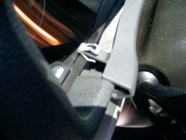

11 11 Screw

12 Remove the panel exposing the work area. Cut the connectors from the fog light harness they will be replaced with the relay base terminals. These are the two gray wires that will supply voltage to the fog lights. Do not cut the ring terminal off of the ground wire that is part of the harness! Align the (Red +12 VDC)and(Black Ground) wires to the end of the gray wires mentioned above and stretch them along the length of wiring harness. Use the friction tape to secure the two wires to the wiring harness at regular intervals. Leave the wires unsecured near the location of the harness ground wire. 12
.")
13 Located at the rear of the battery pan you will notice a wiring harness coming through the fire wall. If you look closely you will notice that the harness is going through something that looks like a diaphragm (black in color). You will also notice that the diaphragm has some small nipple looking things attached to it. Using small wire cutters cut the end off of one of the nipples. Be careful not to tear the diaphragm or cut too much off the end. The space is extremely tight. Tape the end of the fog light wiring harness securing the newly added (Red +12 VDC) and (Black Ground) wire to the gray fog light +12 supply wires. Push the taped end of the wiring harness through the open nipple. Go underneath the dash and look for the fog light harness to the left of the steering column. Pull the harness through and nun it up the dash through the back of the fuse panel. Make sure you leave plenty of wire exposed to work with. This is where you are going to wire the fuse and custom electronics. Fog Light Harness Nipple Under the dash locate the fog light harness place your hand near where the harness comes in contact with the diaphragm 13

14 nipple and pull the harness toward you. At the contact point use the friction tape to loop around the harness building it up on the harness. Two inches on either side of the contact point along the length of the harness should do it. Locate the fog light harness under the hood behind the battery pan and pull slowly out toward the front of the car. Stop when approximately 2 inches of the harness wrapped with the friction tape are exposed. The build up of friction tape should cause the diaphragm nipple to expand around the friction tape and form a tight seal. Do not over do it with the friction tape! 14

15 Fog Light Harness Once you are satisfied that the harness is in place and you have plenty of room to work with on both ends use the split flex tubing under the hood to incase the fog light harness along the entire length. You will expose the fog light ground (ring terminal), the two new (Red +12 VDC)and(Black Ground) wires you added, and the fog light hookups at the end of the harness from the slit or end of the tubing. Use some friction tape at regular intervals along the split tubing to wrap small sections and secure it in place. Make sure you push the split tubing up against the firewall exit point of the harness around the diaphragm to provide some insulation. Take the other end of the harness with the fog light hookups and fish it to the side of the battery, under the air box, and into an opening next to the air box. This should bring the harness to the front of the vehicle. Use zip ties (cable ties) to secure it in place. 15

16 Add the fog lights to the bumper and double check to make sure you have plenty of room to plug the harness into the fog lights. If you are satisfied with you work so far you can bolt the bumper back to the car as outlined in the EMT OEM Fog Light retrofit document. Or wait until the end. Locate the end of the (Red +12 VDC)wire you added to the harness and align it up to the outside of the fuse box where you will bolt it. Cut the excess off and crimp a ring terminal to the end of the wire. Bolt the finished product onto the side of the fuse box (look closely at image for reference). +12 VDC Connection 16
 wire and bolt it to the grounding post.")
17 Located next to the air box are grounding posts. Trim the (Black Ground) wire you added to one of the posts. Save the excess wire you will need it later. Ground Post Crimp a ring terminal to the end of the (Black Ground) wire and bolt it to the grounding post. At this time bolt the brown ground wire that comes with the fog light harness to the grounding post. 17
18 The next step is to build one of these circuits depending on the type of relay that will be used. Solid State Relay Bosch Relay Take the circuit board and snap it in half. You only need one half hold on to the other half incase you make a mistake. The picture below is the bottom view of the circuit this is where the soldering takes place. The reed relay, diode, jumper, and wires plug into the openings on the other end of the board. The reed relay pins are not numbered I used numbers in the diagram for reference. If you have never soldered in the past take some time and practice. Do not clump up the solder on the circuit board otherwise you will not be able to close the project/battery box or even worse you could cause a short. 18

19 Plug the reed relay to the circuit and solder the pins in place. Cut a small piece of left over ground wire and plug it into jumper locations between pins 2 and 3 of the reed relay. Use about 6 inches of left over wire to create the ground lead between the pins 2 and 3. Solder the jumper wire and ground wire to the circuit. The circuit ground wire will eventually be twisted to the (Black Ground) wire that was added to the harness and crimped to one of the relay base terminals ending up on PIN #85 of the solid state relay. Use about 6 inches of left over ground wire to solder into jumper PIN #4 of the reed relay. Plug the diode to the circuit as indicated by the diagram and solder it in place. Make sure you pay attention to the diode polarity otherwise the circuit will not work. The diode has a silver stripe on one end this end should be 19

20 wired to PIN #1 of the reed relay the other end will be connected to the trigger wire. Take the trigger wire supplied with the harness and cut it half. You only need one half save the other as a backup. Strip the cut end of the trigger wire plug it into the circuit and solder in place. You should end up with something like this. Bottom View 20

21 Top View Open the battery box and remove the internal components. If you purchase a project box there is nothing to remove. The springs, wires, and switch must be removed. Use pliers to break off the battery separators running along the length of the box. 21

22 Place the finished circuit board in the battery box. It should snap into place and fit snug. Run the wires through the openings in the battery box. Screw the battery box lid back in place. Specific to the Hella Solid State Relay: On the end of the wire corresponding to jumper PIN #4 of the reed relay crimp a relay base terminal. Plug it into the relay base port corresponding to PIN #86 of the solid state relay. Solder one end of the Mini Blade Fuse Holder to the (Red +12 VDC) wire you added to the fog light harness this will become the fused +12 VDC supply for the relay. Use some heat shrink tubing to insulate the solder point. On the other end of the Mini Blade Fuse Holder crimp a relay base port terminal and plug it into the relay base port corresponding to PIN #30 of the solid state relay. Take the ground wire of the custom circuit and twist it together with the (Black Ground) wire added to the fog light harness. Crimp a base port terminal to the twisted end of the wires. Plug it into the relay base port corresponding to PIN #85 of the solid state relay. 22
23 Take the two gray +12 VDC wires of the fog light harness and twist them together. Crimp a relay base port terminal and plug it into the relay base port corresponding to PIN #87. Specific to the Bosch Relay: On the end of the wire corresponding to jumper PIN #4 of the reed relay crimp a relay base terminal. Plug it into the relay base port corresponding to PIN #86 of the solid state relay. Solder one end of the Mini Blade Fuse Holder to the (Red +12 VDC) wire you added to the fog light harness this will become the fused +12 VDC supply for the relay. Place a base port terminal and some heat shrink tubing to the other end and plug it into relay PIN # 30. Use the remaining red wire to provide +12 VDC to relay PIN # 85. The same supply can be used for both PIN # 30 and PIN # 85 essentially splicing the two together. If so you may want to consider using a larger diameter red wire to compensate for the extra load. The best approach would be to provide separate +12 VDC for these two pins. If you take the second approach then make sure you accommodate this by adding another wire to the harness. If the Bosch relay you purchased is a change over relay (SPDT) type relay take the two gray +12 VDC wires of the fog light harness and twist them together. Crimp a relay base port terminal and plug it into the relay base port corresponding to PIN #87. If the Bosch relay you purchased is a normally open (SPST) type relay crimp a relay base port terminal to each +12 gray wire. Place one wire to PIN #87 and the other to PIN #87a. For both types of relays: Double check to make sure everything is properly wired. Once you are satisfied plug the solid state relay into the base port. Use some 3M double sided squares to secure the relay base port on top of the fuse box (see pictures below). Use some 3M double sided squares to secure the battery box containing the custom circuit to the metal dash support behind the light switches (see pictures below). Plug the end of the trigger wire to the light switch harness PIN #5. 23


24 Custom Circuit Fuse Relay 24

25 Plug the light switch to the light switch harness. Add a fuse to the mini blade fuse holder. Replace the battery and battery skirt. Test the lights to make sure everything is working. Once the test is successful bolt all the remaining pieces together. You are done! 25


26 Some interior pictures: Some exterior pictures: 26


27 27
A&A CORVETTE PERFORMANCE C6 BOOST & FUEL GAUGE INSTALLATION INSTRUCTIONS
 A&A CORVETTE PERFORMANCE C6 BOOST & FUEL GAUGE INSTALLATION INSTRUCTIONS 1. Check your gauges before you take them out of the packaging to make sure they are at 0 (zero) psi for both boost and fuel pressure.
Time needed: ~3h for lid replacement only. Add 1h for operation harness in lid and ~2h more for installing drive unit and cable harness in trunk.
 DIY for replacing trunk lid and/or retrofitting electrical operation of trunk lid. This document is meant to be a support and give advice on the procedure but I will take no responsibility for any damage
I Click on a link tab to jump to that page. Cover Page
 Publication, Duplication, or Retransmission Of This Document Not Expressly Authorized n Writing By The nstall Doctor s Prohibited. Protected By U.S. Copyright Laws. 1997,1998,1999,2000. Factory Radio Other
Guide for Modified Assembly: Lightning McQueen. By: Collin Patterson, University of Delaware. Materials and Tools:
 Guide for Modified Assembly: Lightning McQueen By: Collin Patterson, University of Delaware Materials and Tools: PVC o 40 inches of 1 in diameter PVC o 25 inches of ¾ in PVC o 4 x 1 in elbows o 2 x ¾ in
C5 Sound Deadening & Insulation Kit Interior Removal & Installation Instructions
 C5 Sound Deadening & Insulation Kit Interior Removal & Installation Instructions Ok, let's start with taking the radio bezel dash area off first. Here is what the OEM radio looks like... First you flip
Bill Conkling July 2012
 Bill Conkling July 2012 Introduction: For any ham, there are moments that are priceless, like snagging that elusive rare DX station on a deserted island that hasn t been activated in 52 years. And certainly,
Bi-Xenon Retrofit DIY Instructions
 Bi-Xenon Retrofit DIY Instructions Models: Facelifted E46 with halogen lights fitted as OEM. NOTE: To get pre-2002 cars this functionality, you need to see the amendment. NOTE: Compliments of ScottZHP
Cover Page. Factory Radio Other Documents Available For This Vehicle:
 & nstall Publication, Duplication, or Retransmission Of This Document Not Expressly Authorized n Writing By The nstall Doctor s Prohibited. Protected By U.S. Copyright Laws. 1997,1998,,2000. Factory Radio
I Click on a link tab to jump to that page. Cover Page
 & nstall Publication, Duplication, or Retransmission Of This Document Not Expressly Authorized n Writing By The nstall Doctor s Prohibited. Protected By U.S. Copyright Laws. 1997,1998,1999,2000. Factory
Retrofit Instructions Installing a Sport Heated Steering Wheel - Leather, Multifunction BMW X5, E53, 2001 2006
 Retrofit Instructions Installing a Sport Heated Steering Wheel - Leather, Multifunction BMW X5, E53, 2001 2006 Disclaimer: This set of instructions is simply a guide on how I installed my own heated steering
I Click on a link tab to jump to that page. Cover Page
 & nstall Publication, Duplication, or Retransmission Of This Document Not Expressly Authorized n Writing By The nstall Doctor s Prohibited. Protected By U.S. Copyright Laws. 1997,1998,1999,2000. Factory
73 Chevy C10 Ammeter to Volt Gauge Conversion Mark and Michael Olson 2013 Rev 1.0
 73 Chevy C10 Ammeter to Volt Conversion Mark and Michael Olson 2013 Rev 1.0 The ammeter in my son s 73 Chevy C10 did not work, so we decided to convert it to a more modern volt gauge. We made a number
INSTALLATION INSTRUCTIONS
 Rear Vision System Tailgate Handle Camera Mirror Display 2004-2014 Ford F-150 and 2008-2015 Ford Super Duty (Kit part numbers 9002-9521) Kit Contents: Mirror Tailgate Handle with camera and harness Interior
Walbro 255lph Inline Fuel Pump Install Procedure
 Walbro 255lph Inline Fuel Pump Install Procedure Note: Instructions are based on a single in tank pump with under car OEM VW filter. Total install time for a qualified technician is approximately 2 hrs.
INSTALLATION INSTRUCTIONS
 Rear Vision System Aftermarket and Factory 5.0, 8.4 and 6.1 MyGig Touch Screen Display (Factory Display requires Chrysler/Dodge dealer to activate) 2009 Current* Dodge Ram (Kit part number 1009-6503) *NOTE:
by Myles H. Kitchen M.H. KITCHEN & ASSOCIATES www.auto-electronic.com (2002 X5 4.4 owner) March 2, 2004
 March 2, 2004") INSTALLING THE TEKONSHA PRODIGY ELECTRIC TRAILER BRAKE CONTROL IN THE BMW X5 by Myles H. Kitchen M.H. KITCHEN & ASSOCIATES www.auto-electronic.com (2002 X5 4.4 owner) March 2, 2004 INTRODUCTION The 2000
INSTALLING THE TEKONSHA PRODIGY ELECTRIC TRAILER BRAKE CONTROL IN THE BMW X5 by Myles H. Kitchen M.H. KITCHEN & ASSOCIATES www.auto-electronic.com (2002 X5 4.4 owner) March 2, 2004 INTRODUCTION The 2000
Back-Up Camera Installation Guide
 Hz Hz In This Guide: Back-up camera installation requires connecting power wiring to the existing reverse lighting circuit and adding a chassis ground, as well as routing a video signal cable to the front
INSTALLATION INSTRUCTIONS
 INSTALLATION INSTRUCTIONS Accessory Application Publications No. AII 26327 2004 S2000 Issue Date OCT 2004 PARTS LIST Security System: P/N 08E51-S84-100 Attachment Kit: P/N 08E55-S2A-101 2 Remote controls
WIRE, TERMINAL AND CONNECTOR REPAIR CONDUCTORS
 CONDUCTORS Conductors are needed to complete the path for electrical current to flow from the power source to the working devices and back to the power source. Special wiring is needed for battery cables
ILISC515-A Shift Interlock (Manual Lift Door) 2015 Ford Transit, 3.7L and 3.5L
 2015 Ford Transit, 3.7L and 3.5L") An ISO 9001:2008 Registered Company ILISC515-A Shift Interlock (Manual Lift Door) 2015 Ford Transit, 3.7L and 3.5L Introduction The ILISC515-A is a microprocessor driven system for controlling wheelchair
An ISO 9001:2008 Registered Company ILISC515-A Shift Interlock (Manual Lift Door) 2015 Ford Transit, 3.7L and 3.5L Introduction The ILISC515-A is a microprocessor driven system for controlling wheelchair
specializing in AIR CONDITIONING, PARTS AND SYSTEMS for your classic vehicle PERFECT FIT IN-DASH HEAT/ COOL/ DEFROST 1967-72 CHEVROLET PICKUP
 specializing in AIR CONDITIONING, PARTS AND SYSTEMS for your classic vehicle PERFECT FIT IN-DASH HEAT/ COOL/ DEFROST 1967-72 CHEVROLET PICKUP CONTROL & OPERATING INSTRUCTIONS The controls on your new Perfect
INSTALLATION INSTRUCTIONS
 INSTALLATION INSTRUCTIONS Accessory Application Publications No. AII23628 2003 PILOT Issue Date MAY 2002 PARTS LIST Security System Kit (sold separately): P/N 08E51-S84-100 2 Remote controls Attachment
Parts and Accessories Installation Instructions
 Parts and Accessories Installation Instructions R5 5 Z CD changer retrofit kit MINI (R 5 and R 53) LHD and RHD The installation time is approx..5 hours, but this may vary depending on the condition of
Installing RNS-E SAT NAV for Audi A4
 As one of the major options on the A4 you can get a DVD Satellite Navigation System call the RNS-E. With the help of ebay these sat nav systems are now available to by at a rough cost of 650 plus the cost
CONTENTS TOOLS REQUIRED: Ratchet 13mm Socket 10mm Socket Phillips Screwdriver Pliers Panel Removal Tool. Amp Installation
 CONTENTS 1EA. SUBWOOFER ASSEMBLY P/N RUWRANGLER 1EA. 200 WATT AMP/BRACKET ASSEMBLY P/N RM11JKBTL - Bracket P/N RE08BTL200R - Amp 1EA. POWER HARNESS P/N RHWRANGLERPWR 1EA. OVERLAY HARNESS P/N RHWRANGLER
ADDING AN ELECTRIC AUXILIARY FAN TO RADIATOR STACK ON 03 ALPINE COACH
 ADDING AN ELECTRIC AUXILIARY FAN TO RADIATOR STACK ON 03 ALPINE COACH The original design of the 03 Alpine Coaches (and perhaps other years as well) did not include any kind of engine fan engage mechanism
Projector90 Xenon Headlight Installation Guide
 Projector90 Xenon Headlight Installation Guide Written exclusively for Umnitza s Projector90 Product This step-by-step guide is designed to be used in together with other available documentation including
Figure 2 The fan and shroud also needs to be removed for access to the four a/c compressor bolts and removal of the compressor from the top.
 Here are some pictures to show what s required when replacing the A/C compressor, expansion valve and receiver/drier on a 2001 Volvo V70. Even if you don t replace these A/C parts these pictures can help
BUILT-IN DISHWASHER INSTALLATION INSTRUCTIONS
 BUILT-IN DISHWASHER INSTALLATION INSTRUCTIONS PLEASE READ COMPLETE INSTRUCTIONS BEFORE YOU BEGIN LEAVE INSTALLATION INSTRUCTIONS AND USER'S GUIDE WITH OWNER ALL ELECTRIC WIRING AND PLUMBING MUST BE DONE
Installation of Rear View Camera in a 1995 Roadtrek 190 Popular
 Installation Instructions: 1995 Roadtrek Rear View Camera Page 1 Installation of Rear View Camera in a 1995 Roadtrek 190 Popular Introduction. In the fall of 2010 we investigated rear view cameras for
BMW E46 Convertible. Storage Compartment Lid Hydraulic Cylinder Removal
 BMW E46 Convertible Storage Compartment Lid Hydraulic Cylinder Removal Created by taylor192 of E46Fanatics.com Hosted by Top Hydraulics, without any warranties Page.1 Storage compartment lid hydraulic
Power Window/Power Lock Installation. To begin with you will need all the parts listed below:
 Power Window/Power Lock Installation To begin with you will need all the parts listed below: From Donor Fiero: Fiero power window regulators Power window motors (Generic GM type part) -motors are riveted
Clio 2 Pictorial Installation Guide
 Clio 2 Pictorial Installation Guide Fastchip imfd gauge module support for PLX Devices: DM-5 Digital Gauges System Driver - RSTuner VCI and software supplied by: http://www.fastchip.nl Gauges supplied
For a simple splice connection look at figure 21. This basic type of splice can be used almost exclusively when hooking up your wiring.
 Page 1 of 10 IMPORTANT: Before starting installation, please be sure that all items which were supplied with the kit are accounted for. Note: These instructions are to be used in conjunction with the instructions
E30 Fog Light Wiring Instructions Conversions Allowing for Independent Fog Light Operation in Sealed Beam and Ellipsoid Style Headlight Systems
 E30 Fog Light Wiring Instructions X Mon Revision A 26 April, 2007 This document details the steps required to convert the headlight dependent fog lights of the E30 chassis BMW to an array of user configurable
VW Jetta, Golf, New Beetle 1.9L TDi Unichip PnP Installation Instructions
 VW Jetta, Golf, New Beetle 1.9L TDi Unichip PnP Installation Instructions and Warranty Information Tools Required 10mm combination wrench, 13mm Socket (Jetta/Golf only), 3/8-inch or ¼-Inch drive ratchet,
1999.5-2001 Audi A4 (B5) HID conversion installation instructions
 HID conversion installation instructions") 1 of 5 10/26/2007 4:48 PM 1999.5-2001 Audi A4 (B5) HID conversion installation instructions Tools Needed: A drill 1" hole saw T27 Torx bit and driver with a 4" extension Extendable magnet Pliers or A drill
1 of 5 10/26/2007 4:48 PM 1999.5-2001 Audi A4 (B5) HID conversion installation instructions Tools Needed: A drill 1" hole saw T27 Torx bit and driver with a 4" extension Extendable magnet Pliers or A drill
UNIVERSAL LUMBAR INSTALLATION INSTRUCTIONS
 UNIVERSAL LUMBAR INSTALLATION INSTRUCTIONS CONTENTS Parts List... 2 Parts Diagram... 2 Helpful Hints... 3 Installation... 4 Operation and Troubleshooting Guide... 6 Warranty Information... 8 Form #3132,
I Click on a link tab to jump to that page
 & nstall Publication, Duplication, or Retransmission Of This Document Not Expressly Authorized n Writing By The nstall Doctor s Prohibited. Protected By U.S. Copyright Laws. 1997,1998,1999,2000. Factory
Installation Instructions
 520 Installation Instructions Thank you very much for purchasing PIAA product. Please read this entire manual before installation and use of this product. For Installers Please give this Installation Manual
Part Name/Description Part Number Quantity. Power Cable 4000950-5 1
 Note: Indented items indicate parts included in an assembly listed above Part Name/Description Part Number Quantity Power Cable 4000950-5 1 Raven Harness Adapter Kit 4100525 1 Installation Instructions
TOYOTA TUNDRA 2015 Billet Grille w/led DRL
 TOYOTA TUNDRA 2015 Billet Grille w/led DRL Part Number: 00016-34088 Accessory Code: BG3000 Conflicts Models 1794 and Platinum Kit Contents Item # Quantity Reqd. Description 1 2 LED DRL 2 1 Driver Box 3
Odyssey of the Mind Technology Fair. Simple Electronics
 Simple Electronics 1. Terms volts, amps, ohms, watts, positive, negative, AC, DC 2. Matching voltages a. Series vs. parallel 3. Battery capacity 4. Simple electronic circuit light bulb 5. Chose the right
KEYLESS ENTRY UPGRADE SECURITY SYSTEM for 2004 TOYOTA HIGHLANDER
 KEYLESS ENTRY UPGRADE SECURITY SYSTEM for 2004 TOYOTA HIGHLANDER DEALER SERVICE AND INSTALLATION MANUAL KIT NO. 00016-30915 Contents PARTS LIST... 2 PARTS ILLUSTRATIONS... 2 VEHICLE PREPARATION... 3 INSTALLING
Control Box Wiring For PRSstandard Tool
 888-680-4466 ShopBotTools.com Control Box Wiring For PRSstandard Tool Copyright 2016 ShopBot Tools, Inc. page 1 Copyright 2016 ShopBot Tools, Inc. page 2 Table of Contents Introduction:...5 Installation:...5
- power windows - alarm system - electric door mirror control - door warning light - central locking - seat memory
 Door Wiring Harness Plug Connections Binder -, Electrics Vehicle Type: (86) Model Year: 7 (V) Concern: Door wiring harness plug connections X11 / X12. Information: The rubber boot for the door connector
INSTALLATION INSTRUCTIONS: Viewline 52 mm
 -5 Safety information The product was developed, manufactured and inspected according to the basic safety requirements of EC Guidelines and state-of-the-art technology. The instrument is designed for use
WARNING! REQUIRED TOOLS & SUPPLIES: HIGH VOLTAGE
 INSTRUCTIONS Product: GEM Electric Motorcars Models: All Subject: Instructions for installing Stereo Accessory Estimated Completion Time:.75 Hours Parts: See Page # 7 REQUIRED TOOLS & SUPPLIES: (1) 3/8
Before installation it is important to know what parts you have and what the capabilities of these parts are.
 INSTALLATION GUIDE Before installation it is important to know what parts you have and what the capabilities of these parts are. The Recon XZT is the smallest and most powerful gauge of its kind. With
How to modify a car starter for forward/reverse operation
 How to modify a car starter for forward/reverse operation Ok, start by choosing a starter. I took a starter out of an older style Nissan Sentra. I chose this particular starter for two reasons: 1. It was
Alfa Romeo 147 On board instruments installation guide
 Alfa Romeo 147 On board instruments installation guide Alfa Romeo 147 On board instruments installation guide This guide is describing how I installed oil temperature and oil pressure gauges to my Alfa
Mazda CX7 2007-09 99-7508
 INSTALLATION INSTRUCTIONS FOR PART 99-7508 APPLICATIONS Mazda CX7 2007-09 99-7508 KIT FEATURES DIN Radio Provision with Pocket ISO Mount Radio Provision with Pocket Double DIN Mount Radio Provision Stacked
with installation dynafact boost GAUGE this manual is for use with systems 64050-64054
 owners manual with installation instructions dynafact boost GAUGE this manual is for use with systems 64050-64054 GENERAL INSTALLATION PRACTICES This manual is an installation guide for all 1. Banks DynaFact
INSTALLATION GUIDE OWNER S GUIDE
 INSTALLATION GUIDE OWNER S GUIDE KEYLESS ENTRY MODELS KE100 / KE150 / 1702 CONTENTS System Features... 1 System Components... 1 Technical Assistance... 1 Before You Begin... 1 Precautions... 1-2 Making
Multi Function, User Configurable Remote Vehicle Security System with 4 Button Replaceable Membrane Remote Transmitter
 MODEL PRO-9744 INSTALLATION MANUAL Multi Function, User Configurable Remote Vehicle Security System with 4 Button Replaceable Membrane Remote Transmitter This System Allows The Transmitter Buttons To Be
PERFECT FIT SERIES IN-DASH HEAT/ COOL/ DEFROST 1967 CHEVROLET IMPALA
 specializing in AIR CONDITIONING, PARTS AND SYSTEMS for your classic vehicle PERFECT FIT SERIES IN-DASH HEAT/ COOL/ DEFROST 1967 CHEVROLET IMPALA CONTROL & OPERATING INSTRUCTIONS The controls on your new
General Tips for Installation of mobridge into Porsche Vehicles
 General Tips for Installation of mobridge into Porsche Vehicles Disclaimer: the information herein is provided as a convenient as-is reference only. The information herein is not guaranteed to be accurate
P150SC15. Designed for 2015 Ford F150 Super-Cab and Super-Crew vehicles without Sony System. 2015 Stillwater Designs P150SC15-A2-20150813
 P150SC15 Designed for 2015 Ford F150 Super-Cab and Super-Crew vehicles without Sony System Subwoofer Assembly Amplifier Assembly Amplifier Harness 2015 Stillwater Designs P150SC15-A2-20150813 M6 Bolt M6
2003/2004/2005 TOYOTA COROLLA
 2003/2004/2005 TOYOTA COROLLA KEYLESS ENTRY UPGRADE SECURITY SYSTEM INSTALLATION INSTRUCTIONS KIT NO. 00016-30120 SPECIAL NOTE: Installation Sequences After TMS and Safety mandated preparatory steps have
Installation Instructions: Electrical System for Towing Hitch... 3
 ... 3 Installation Instructions: Electrical System for Towing Hitch... 3 321 527 391 103-002 - 51/12 VW Polo A05 RHD Westfalia 321 525 300 143 VW Polo V RHD, 06/09-321 527 300 143 VW Polo V RHD, 06/09-4
User s Manual. BNC Mini-High Res, 75 Ohm Termination Kit Connector Installation Guide (60-073-01)
") User s Manual BNC Mini-High Res, 75 Ohm Termination Kit Connector Installation Guide (60-073-01) BNC Termination Kit Instructions This document is a compilation of Extron s instructions, together with
User s Manual BNC Mini-High Res, 75 Ohm Termination Kit Connector Installation Guide (60-073-01) BNC Termination Kit Instructions This document is a compilation of Extron s instructions, together with
Installation Instructions
 Installation Instructions For Use with PXPV230, PXPV265, PXPD230, and PXPD265 models Attention! - Please read these instructions completely before attempting installation. Always unplug the power supply
Anderson Powerpoles. Powerpole Assembly Instructions for SCOUT, NAVIGATOR AND RANGER ROV s
 Anderson Powerpoles Powerpole Assembly Instructions for SCOUT, NAVIGATOR AND RANGER ROV s Anderson Powerpoles Power Connections NEW in 2016!!! ELEC-010E: Power supply connections will be Red/Black Anderson
Juice Box Stages 1&2 135&335 Installation Guide 5/10/08
 Tools Required: 8mm socket or nut driver Small flat head screwdriver Electrical tape, masking tape, or shrink tube Pep talk: Although the install looks daunting at first, once you get the learning curve
LED Wiring and Connections
 LED Wiring and Connections A Handbook of How-to Manuals 2009 usledsupply. All Rights Reserved. Index These step by step how to manuals will give you the foundation necessary to use your new LED lights.
5 Mechanisms and accessories
 5 Mechanisms and accessories 51A SIDE OPENING ELEMENT MECHANISMS 52A NON-SIDE OPENING ELEMENT MECHANISMS 54A WINDOWS 55A EXTERIOR PROTECTION 56A EXTERIOR EQUIPMENT 57A INTERIOR EQUIPMENT X79 NOVEMBER 2009
INSTALLATION INSTRUCTIONS
 INSTALLATION INSTRUCTIONS Accessory Application Publications No. ACCORD All 30209 2-AND 4-DOOR SYSTEM (VP, LX, SE) Issue Date AUG 2005 PARTS LIST Security System Attachment: P/N 08E55-SDA-100A Unit panel
INSTALLATION INSTRUCTIONS
 INSTALLATION INSTRUCTIONS Accessory Application Publications No. All 24393 ACCORD (DX, LX) SYSTEM 2-AND 4-DOOR Issue Date AUG 2002 PARTS LIST Security System Attachment (LX): P/N 08E55-SDA-100A Unit panel
TOYOTA TACOMA 2008- HANDS FREE BLU LOGIC Preparation
 TOYOTA TACOMA 2008- HANDS FREE BLU LOGIC Preparation Part #: PT923-00112 Conflicts: JBL Audio, Factory Navigation NOTE: Part number of this accessory may not be the same as the part number shown. Kit Contents:
How To Power A 12 Volt Relay On A Car Or Truck
 Relay modification for older bikes Please read this in conjunction with the schematics at the end. All the options are shown, but you can opt to do any one or more as you wish. The electrical connections
MGA Alternator Conversion
 MGA Alternator Conversion Installation Instructions For 1955 to 1962 MGA PART # 130-078 and #130-088 440 Rutherford St. P.O. Box 847 Goleta, CA 93117 1-800-667-7872 FAX 805-692-2525 www.mossmotors.com
BILLET HEADLAMP WITH SHORT/TALL MOUNTS
 -J099 REV. 00-0- BILLET HEADLAMP WITH SHORT/TALL MOUNTS GENERAL Kit Number 9-0, 9-0 Models Kit 9-0 is a -/ inch headlamp and kit 9-0 is a -/ inch headlamp. Both kits will fit the models listed in Table.
Diagnosing and Understanding Starting Problems on the ZR-1 Marc Haibeck 28-Sep-13
 Diagnosing and Understanding Starting Problems on the ZR-1 Marc Haibeck 28-Sep-13 There are three basic failure conditions: - A VATS security system lockout - A click from the starter solenoid but no engine
INSTRUCTIONS FOR THE INSTALLATION AND OPERATION OF ACTIVATOR II
 INSTRUCTIONS FOR THE INSTALLATION AND OPERATION OF ACTIVATOR II ELECTRONIC TRAILER BRAKE CONTROL 5500 FOR 2, 4, 6 & 8 BRAKE SYSTEMS IMPORTANT: READ AND FOLLOW THESE INSTRUCTIONS CAREFULLY. KEEP THESE INSTRUCTIONS
VW GOLF Mk4 TDI FRONT MOUNTING INTERCOOLER INSTALLATION INSTRUCTIONS
 VW GOLF Mk4 TDI FRONT MOUNTING INTERCOOLER INSTALLATION INSTRUCTIONS Tools required: 10mm/13mm socket and 3/8 drive ratchet with extension Torx T20/25/30 screwdrivers or bits Phillips head screwdriver,
1R / 4-BUTTON SERIES
 Button 1 1R / 4-BUTTON SERIES VEHICLE SECURITY SYSTEM Standard Features: Two 4-Button Remote Transmitters Status indicator (LED) Valet / override switch Multi-tone siren Dual stage impact detector Remote
Installation Instructions: Electrical System for Towing Hitch...3
 Fehler! Textmarke nicht definiert....3 Installation Instructions:...3 317 056 391 104-002 - 22/07 Westfalia Skoda 317 056 300 153 Skoda Octavia II (1Z), 4x4, RS, RHD 3 2 1 1 2 3 4 5 6 7 2 317 056 391 104-002
Universal Vehicle Power Supply 9007AX01. Installation Instructions
 Universal Vehicle Power Supply 9007AX01 Installation Instructions Disclaimer Honeywell International Inc. ( HII ) reserves the right to make changes in specifications and other information contained in
Spreader Light Bulb Replacement Instructions
 Spreader Light Bulb Replacement Instructions IMPORTANT: DISCONNECT LIGHT FROM BATTERY BEFORE PROCEEDING. FAILURE TO DO SO MAY RESULT IN PERSONAL INJURY OR OTHER DAMAGE. Tools Needed You will need the following
INSTALLATION INSTRUCTIONS FOR 2006-2009 VW MK5
 CI100018 INSTALLATION INSTRUCTIONS FOR 2006-2009 VW MK5 Rabbit, Jetta 2.5L These instructions are applicable to vehicles equipped with either manual or automatic transmissions Thank you for choosing to
Coolant heater. Thermo Top - Z/C additional heating system. Installation instructions. Volvo S60, Volvo V70, and Volvo S80 Beginning Model Year: 2000
 Coolant heater Thermo Top - Z/C additional heating system Approval code ~~~ S 9 Installation instructions Volvo S60, Volvo V70, and Volvo S80 Beginning Model Year: 000 6 6 7 8 Volvo XC70 Beginning Model
Vehicle Alarm System With Channel 2 Auxiliary Output Installation Instructions
 Model PRO 9842 Installation Manual Vehicle Alarm System With Channel 2 Auxiliary Output Installation Instructions This Unit Is Intended For Installation In Vehicles With 12 Volt Negative Ground Electrical
ELECTRONICS G H I J K L M
 ELECTRONICS TM LASER INSTALLATION INSTRUCTIONS PARTS KIT Parts Kit includes the following: A- (1) Universal Mounting Bracket A B- (1) Red L.E.D. Laser Alert Light C- (1) Piezo Beeper w/ O Ring Tape D-
TABLE OF CONTENTS. I. TROUBLESHOOTING... 2 - Section 1.01: Common Problems/Solutions... 2
 BAL Accu-Slide System I. Table of Contents TABLE OF CONTENTS I. TROUBLESHOOTING... 2 - Section 1.01: Common Problems/Solutions... 2 II. GETTING STARTED... 5 - Section 2.01: Tools You Will Need... 5 - Section
TOYOTA Tundra 2007 - BACK-UP CAMERA SYSTEM Preparation
 Preparation Part Number(s): PT233-34070, PT923-35070-11, PT923-35070-43 NOTE: Part number of this accessory may not be the same as part number shown. Back Up Monitor Kit Contents PT923-35070-11 / PT923-35070-43
How to choose the very best connectors for your speaker cables and enjoy superb sound from your music system
 Not all speaker plugs sound the same How to choose the very best connectors for your speaker cables and enjoy superb sound from your music system By Graham Nalty MA Not all speaker plugs sound the same
Table of Contents. www.hunterfan.com. What to Expect with. Preparation. Tools Needed. Wiring. Hanging the Fan. Blades. Motor Housing.
 www.hunterfan.com Table of Contents What to Expect with Your Installation 30 inches Hanging the Fan Wiring 8 Maintenance, Operation & Cleaning Light Kit 13??? 14 1 9 Troubleshooting 11 5 Blades Motor Housing
Installation Instructions
 Installation Instructions for EVS II Security and Keyless Entry Systems Note: It is recommended that this installation take place prior to rustproofing. The individual delivering the vehicle should review
E30 Headlight Wiring Instructions Converting Sealed Beam Systems to Ellipsoid/European Style Headlight Systems Utilizing Single Filament Bulbs
 E30 Headlight Wiring Instructions Converting Sealed Beam Systems to Ellipsoid/European Style Headlight Systems Utilizing Single Filament Bulbs X Mon This document details the steps required to converting
Step by step guide to installing your own Ku Band satellite dish
 Step by step guide to installing your own Ku Band satellite dish If you don't feel comfortable installing your own system, your local TV Aerial or Handyman can easily follow these helpful guidelines for
INSTALLATION MANUAL. Installation Instructions
 INSTALLATION MANUAL Power-Pole Signature Series Shallow Water Anchor Installation Instructions CAUTION: Read this instruction manual carefully. Become familiar with the controls and know how to operate
GENUINE PARTS INSTALLATION INSTRUCTIONS
 GENUINE PARTS INSTALLATION INSTRUCTIONS DESCRIPTION: Illuminated Kick Plate APPLICATION: Rogue (2011) PART NUMBER: 999G6 GX010 KIT CONTENTS: Item A B C G H QTY 1 1 1 D 1 E 1 F 3 15 6 Description Kick Plate,
BMW Parts and Accessories Installation Instructions
 BMW Parts and Accessories Installation Instructions Retrofit Anti-theft Alarm System (DWA) series-identical retrofit for BMW 5 Series saloon and touring (E 9, E 9/) left-hand drive F 9 005 W Installation
Boxster. Technical Information. Service 3/99 9415. Litronic Retrofit Kit
 Litronic Retrofit Kit 9 3/99 9415 Binder - 9, Electrics This bulletin replaces bulletin Grp. 9, #3/99, dated 5-20-99. Vehicle Type: Model Year: Concern: Information: As of 1997 (V) Retrofitting Litronic
FRONT BUMPER INSTALLATION INSTRUCTIONS 2007-2011 DODGE / MERCEDES SPRINTER
 Aluminess Products Inc 9402 Wheatlands Ct. #A Santee, CA 92071 619-449-9930 FRONT BUMPER INSTALLATION INSTRUCTIONS 2007-2011 DODGE / MERCEDES SPRINTER Please read before beginning Stainless steel hardware
INSTALLATION INSTRUCTIONS: Viewline 85 mm
 1-10 1 Safety information The product was developed, manufactured and inspected according to the basic safety requirements of EC Guidelines and state-of-the-art technology. The unit is designed for use
INSTALLATION MANUAL 3RP / 5RP 4-BUTTON SERIES VEHICLE SECURITY SYSTEMS
 3RP / 5RP 4-BUTTON SERIES VEHICLE SECURITY SYSTEMS INSTALLATION MANUAL Before you begin the installation Read the INSTRUCTIONS! Always use a multi-meter when verifying vehicle wiring. Before mounting the
AEROMOTIVE Part # 16302 INSTALLATION INSTRUCTIONS
 AEROMOTIVE Part # 16302 INSTALLATION INSTRUCTIONS CAUTION: Installation of this product requires detailed knowledge of automotive systems and repair procedures. We recommend that this installation be carried
HYDRA HV OPERATION MANUAL. 2.0 Making Connections on your HYDRA speed control. Rosin core electrical solder
 HYDRA HV OPERATION MANUAL Starting Power Safe power on arming program helps prevent motor from accidentally turning on. Always use extreme care with high power systems. Auto shut down when signal is lost