R&TTE (1999/5/EC) Directive ETSI EN V1.8.1: 2012 TEST REPORT
|
|
|
- Arthur Simpson
- 9 years ago
- Views:
Transcription

1 Page: 1 of 51 R&TTE (1999/5/EC) Directive ETSI EN V1.8.1: 2012 TEST REPORT FOR Product Name: Brand Name: Model No.: Model Difference: Report No.: TomTom Cardio GPS Watch TomTom 8RA0 N/A ER/2014/20023 Prepared for: Prepared by: TomTom International BV Rembrandtplein CT Amsterdam The Netherlands SGS Taiwan Ltd. Electronics & Communication Laboratory No.134, Wu Kung Road, New Taipei Industrial Park, Wuku District, New Taipei City, Taiwan Note: This report shall not be reproduced except in full, without the written approval of SGS Taiwan Ltd. This document may be altered or revised by SGS Taiwan Ltd. personnel only, and shall be noted in the revision section of the document.
2 Page: 2 of 51 Applicant: Product Name: Brand Name: Model No.: Model Difference: File Number: VERIFICATION OF COMPLIANCE TomTom International BV Rembrandtplein CT Amsterdam The Netherlands TomTom Cardio GPS Watch TomTom 8RA0 N/A ER/2014/20023 Date of test: Feb. 21, 2014 ~ Feb. 27, 2014 Date of EUT Received: Feb. 21, 2014 APPLICABLE STANDARDS STANDARD TEST RESULT ETSI EN V1.8.1: 2012 Complied The above equipment was tested by SGS Taiwan Ltd., Electronics & Communication Laboratory for compliance with the requirements set forth in the European Standard ETSI EN V1.8.1: 2012 under R&TTE Directive 1999/5/EC Class II. The results of testing in this report apply to the product system that was tested only. Other similar equipment will not necessarily produce the same results due to production tolerance and measurement uncertainties. Test By: Date: Feb. 27, 2014 Marcus Tseng / Engineer Prepared By: Date: Feb. 27, 2014 Julia Chang / Clerk Approved By: Date: Feb. 27, 2014 Jim Chang / Supervisor
3 Page: 3 of 51 Version Version No. Date Description 00 Feb. 27, 2014 Initial creation of document
4 Page: 4 of 51 TABLE OF CONTENTS PAGE 1. DESCRIPTION OF EQUIPMENT UNDER TEST (EUT) DESCRIPTION OF TEST MODES GENERAL DESCRIPTION OF APPLIED STANDARDS TEST FACILITY SUPPORT EQUIPMENT MEASUREMENT UNCERTAINTY SUMMARY OF TEST RESULTS MEASUREMENT EQUIPMENT USED: ETSI EN SUB-CLAUSE & RF OUTPUT POWER ETSI EN SUB-CLAUSE POWER SPECTRAL DENSITY ETSI EN SUB-CLAUSE OR DUTY CYCLE, TX-SEQUENCE, TX-GAP ETSI EN SUB-CLAUSE DWELL TIME, MINIMUM FREQUENCT OCCUPATION AND HOPPING SEQUENCE ETSI EN SUB-CLAUSE HOPPING FREQUENCY SEPARATION ETSI EN SUB-CLAUSE OR MEDIUM UTILISATION ETSI EN SUB-CLAUSE OR ADAPTIVITY (ADAPTIVE FREQUENCY HOPPING) ETSI EN SUB-CLAUSE OR OCCUPIED CHANNEL BANDWIDTH ETSI EN SUB-CLAUSE OR TRANSMITTER UNWANTED EMISSIONS IN THE OOB DOMAIN ETSI EN SUB-CLAUSE OR TRANSMITTER UNWANTED EMISSIONS IN THE SPURIOUS DOMAIN ETSI EN SUB-CLAUSE OR RECEIVER SPURIOUS EMISSIONS ETSI EN SUB-CLAUSE & RECEIVER BLOCKING PHOTOGRAPHS OF SET UP PHOTOGRAPHS OF EUT... 39
5 Page: 5 of DESCRIPTION OF EQUIPMENT UNDER TEST (EUT) General: Product Name: Brand Name: Model No.: Model Difference: TomTom Cardio GPS Watch TomTom 8RA0 N/A Hardware Version: 1.0 Software Version: 1.5 USB Dock: (1.5mm & 1.0mm) Power Supply: Model No.: 4UJ0, Brand Name: TomTom 3.7Vdc (0.7Wh) Rechargeable Lithium Ion battery Bluetooth: Bluetooth Version: Channel number: Modulation type: Rated Power (EIRP): Frequency Range: Antenna Designation: V4.0 single mode(gfsk) 40 channels GFSK -5.14dBm 2.402GHz 2.480GHz Mono-pole Antenna, -5.82dBi The EUT is compliance with Bluetooth standard. This test report applies for Bluetooth 4.0 function.
6 Page: 6 of DESCRIPTION OF TEST MODES The EUT has been tested under Operating and standby condition. And used to control the EUT for staying in engineering mode that enables selectable of channel, and capable of continuous transmitting and constant receiving mode. RF output power Bluetooth 4.0: Lowest (2402MHz), Mid (2442MHz) and Highest (2480MHz) Power Density Bluetooth 4.0: Lowest (2402MHz), Mid (2442MHz) and Highest (2480MHz) Occupied Bandwidth: Bluetooth 4.0: Lowest (2402MHz), Mid (2442MHz) and Highest (2480MHz) Transmitter unwanted emissions in the out-of-band domain: Bluetooth 4.0: Lowest (2402MHz), Mid (2442MHz) and Highest (2480MHz) * The selection of modulation scheme is based on output power that reveals the highest value Transmitter unwanted emissions in the spurious domain: Bluetooth 4.0: Lowest (2402MHz)and Highest (2480MHz) Receiving Spurious Emission: Bluetooth 4.0: Lowest (2402MHz)and Highest (2480MHz)
7 Page: 7 of 51 Normal test conditions : Temperature : + 15 to 35 Relative humidity: 20 % to 75 % Normal power source The normal test voltage for the equipment shall be the nominal voltage for which the equipment was designed. (3.7Vdc) Extreme Condition: Extreme temperatures For tests at extreme temperatures, measurements shall be made over the extremes of the operating temperature range as declared by the manufacturer. Low Temperature: -20 High Temperature: 60 Extreme power source voltages For tests at extreme voltages, measurements shall be made over the extremes of the power source voltage range as declared by the manufacturer. When the equipment under test is designed for operation as part of and powered by another system or piece of equipment, than the limit values of the host equipment or combined equipment as stated by the manufacturer shall apply to the combination to be tested. Normal Voltage: 3.7Vdc 3. GENERAL DESCRIPTION OF APPLIED STANDARDS The EUT According to the Specifications, it must comply with the requirements of the following standards: ETSI EN V1.8.1 : 2012 Electromagnetic compatibility and Radio spectrum Matters (ERM) ; Wideband transmission systems; Data transmission equipment operating in the 2.4GHz ISM band and using wide band modulation techniques: 4. TEST FACILITY SGS Taiwan Ltd. Electronics & Communication Laboratory No.134, Wu Kung Road, New Taipei Industrial Park, Wuku District, New Taipei City, Taiwan A 11m*6m*6m fully anechoic chamber was used for the radiated spurious emissions test.
8 Page: 8 of SUPPORT EQUIPMENT Fig. 5-1 Configuration of Tested System Notebook EUT Table 5-1 Equipment Used in Tested System Model/ Item Equipment Mfr/Brand Series No. Data Cable Power Cord Type No. 1. BT Test Software BlueSuite TERATERM Version 4.75 N/A N/A 2. Notebook DELL D shielding Un-shielding
9 Page: 9 of MEASUREMENT UNCERTAINTY Where relevant, the following measurement uncertainty levels have been calculated in accordance with TR This uncertainty represents an expanded uncertainty expressed at approximately the 95% confidence level using a coverage factor of k=2. This lab s measurement uncertainty ULab, is low than Table 7: Maximum measurement uncertainty of ETSI EN , therefore compliance is deemed to occur if no measured disturbance exceeds the disturbance limit. Occupied Channel Bandwidth ±1.3dB Total RF power, conducted ±1.3dB RF power density, conducted ±1.3dB Unwanted Emissions, conducted ±1.3dB All emissions, radiated ±4.74dB Temperature ±0.8 C Humidity ±4.7% DC and low frequency voltages ±1% Time ±3% Duty Cycle ±2.5%
10 Page: 10 of SUMMARY OF TEST RESULTS The EUT has been tested according to the following specifications: EN V ( ) Clause Test Parameter Remarks Pass/Fail or RF Output Power Applicable Pass Power Spectral Density Applicable Pass or Duty cycle, Tx-Sequence, Tx-gap N/A N/A Dwell time, Minimum Frequency Occupation & Hopping Sequence N/A N/A Hopping Frequency Separation N/A N/A or Medium Utilisation N/A N/A or Adaptivity Applicable N/A Or Occupied Channel Bandwidth Applicable Pass or or or or Transmitter unwanted emissions in the OOB domain Transmitter unwanted emissions in the spurious domain Applicable Applicable Pass Pass Receiver spurious emissions Applicable Pass Receiver Blocking N/A N/A
11 Page: 11 of MEASUREMENT EQUIPMENT USED: 8.1. Conducted Emission Conducted Emission Test Site EQUIPMENT TYPE MFR MODEL NUMBER SERIAL NUMBER LAST CAL. CAL DUE. EXA Spectrum Analyzer Agilent N9010A MY /20/ /19/2015 Spectrum Analyzer Agilent E4440A MY /15/ /14/2014 Temperature Chamber TERCHY MHG-120LF /06/ /05/2014 DC Block Mini-Circuits BLK-18-S+ 1 02/28/ /27/2014 Attenuator Mini-Circuit BW-S10W /28/ /27/2014 Splitter Agilent 11636B /28/ /27/2014 DC Power Supply Agilent E3640A KR /24/ /23/2014 Power Sensor Agilent U2021X MY /08/ /07/2014 Power Sensor Agilent U2021X MY /08/ /07/2014
12 Page: 12 of ETSI EN SUB-CLAUSE & RF OUTPUT POWER 9.1. Limit: FHSS: The maximum RF output power for adaptive Frequency Hopping equipment shall be equal to or less than 20 dbm. The maximum RF output power for non-adaptive Frequency Hopping equipment, shall be declared by the supplier. See clause m). The maximum RF output power for this equipment shall be equal to or less than the value declared by the supplier. This declared value shall be equal to or less than 20 dbm. Other than FHSS: For adaptive equipment using wide band modulations other than FHSS, the maximum RF output power shall be20 dbm. The maximum RF output power for non-adaptive equipment shall be declared by the supplier and shall not exceed 20 dbm. See clause m). For non-adaptive equipment using wide band modulations other than FHSS, the maximum RF output power shall be equal to or less than the value declared by the supplier. This limit shall apply for any combination of power level and intended antenna assembly Measurement Equipment Used: Refer to section 8.1 in this report Test Setup: Temperature Chamber Spectrum analyzer / AV power meter EUT Sensor Variable AC or DC power supply 9.4. Test Procedure: See Sub-Clause of ETSI EN for the test conditions See Sub-Clause of ETSI EN for conducted measurement method.
13 Page: 13 of Equivalent Isotropic Radiated Power E.I.R.P. Test Mode: Bluetooth 4.0 Modulation type: GFSK Test Date: 02/21/2014 Antenna assembly gain: dbi EIRP = A (Average Power ) + G TRANSMITTER POWER (dbm) TEST CONDITIONS Temp (-20) C Vnom 3.7 V Temp (25) C Vnom 3.7 V Temp (60) C Vnom 3.7 V Limit Lowest Frequency (CH Low) Middle Frequency (CH Mid) Highest Frequency (CH High) EIRP = dbm EIRP = dbm EIRP = dbm Av = dbm Av = dbm Av = dbm EIRP = dbm EIRP = dbm EIRP = dbm Av = dbm Av = dbm Av = dbm EIRP = dbm EIRP = dbm EIRP = dbm Av = 0.68 dbm Av = dbm Av = dbm 20dBm Note: 1. E.I.R.P.. shall be calculated from the above measured power output A, and the applicable antenna assembly gain G in dbi. 2. Av is the Average value at antenna port. *offset: 2.1dBm being set in compensation for the cable loss
14 Page: 14 of ETSI EN SUB-CLAUSE POWER SPECTRAL DENSITY Limit: For equipment using wide band modulations other than FHSS, the maximum Power Spectral Density is limited to10 dbm per MHz Measurement Equipment Used: Refer to section 8.1 in this report Test Setup: Refer to section 9.3 in this report Test Procedure: See Sub-Clause of ETSI EN for the test conditions See Sub-Clause of ETSI EN for conducted measurement method.
15 Page: 15 of Test Result: Test results: Bluetooth 4.0 Modulation type: GFSK Test Date: 02/21/2014 TEST CONDITIONS Temp(25) C Vnom 3.7 V Measured power density Reading(A) / dbm Power Density CH Low CH Mid CH High
16 Page: 16 of ETSI EN SUB-CLAUSE OR DUTY CYCLE, TX-SEQUENCE, TX-GAP Limit: For non-adaptive FHSS equipment, the Duty Cycle shall be equal to or less than the maximum value declared by the supplier. In addition, the maximum Tx-sequence time shall be 5 ms while the minimum Tx-gap time shall be 5 ms Measurement Equipment Used: Refer to section 8.1 in this report Test Setup: Refer to section 9.3 in this report Test Procedure: See Sub-Clause of ETSI EN for the test conditions See Sub-Clause of ETSI EN for conducted measurement method Test Result: N/A for Modulation Technology other than FHSS
17 Page: 17 of ETSI EN SUB-CLAUSE DWELL TIME, MINIMUM FREQUENCT OCCUPATION AND HOPPING SEQUENCE Limit: Non-adaptive frequency hopping systems The accumulated Dwell Time on any hopping frequency shall not be greater than 15 ms within any period of 15 ms multiplied by the minimum number of hopping frequencies (N) that have to be used. Non-adaptive medical devices requiring reverse compatibility with other medical devices placed on the market when earlier versions of the present document were harmonised, are allowed to have an operating mode in which the maximum dwell time is 400 ms. The hopping sequence(s) shall contain at least N hopping frequencies where N is 15 or 15 divided by the minimum Hopping Frequency Separation in MHz, whichever is the greater. The Minimum Frequency Occupation Time shall be equal to one dwell time within a period not exceeding four times the product of the dwell time per hop and the number of hopping frequencies in use. Adaptive frequency hopping systems Adaptive Frequency Hopping systems shall be capable of operating over a minimum of 70 % of the band specified in clause 1. The maximum accumulated dwell time on any hopping frequency shall be 400 ms within any period of 400 ms multiplied by the minimum number of hopping frequencies (N) that have to be used. The hopping sequence(s) shall contain at least N hopping frequencies at all times, where N is 15 or 15 divided by the minimum Hopping Frequency Separation in MHz, whichever is the greater. The Minimum Frequency Occupation Time shall be equal to one dwell time within a period not exceeding four times the product of the dwell time per hop and the number of hopping frequencies in use. Other Requirements Frequency Hopping equipment shall transmit on a minimum of two hopping frequencies. For non-adaptive Frequency Hopping equipment, when not transmitting on a hopping frequency, the equipment has to occupy that frequency for the duration of the typical dwell time. For Adaptive Frequency Hopping systems using LBT based DAA, if a signal is detected during the CCA, these systems may jump immediately to the next frequency in the hopping sequence (see clause point 2) provided the limit for maximum dwell is respected Measurement Equipment Used: Refer to section 8.1 in this report Test Setup: Refer to section 9.3 in this report Test Procedure: See Sub-Clause of ETSI EN for the test conditions See Sub-Clause of ETSI EN for conducted measurement method.
18 Page: 18 of Test Result: Dwell Time: N/A for Modulation Technology other than FHSS Hopping channel Result: N/A for Modulation Technology other than FHSS Hopping sequence N/A for Modulation Technology other than FHSS
19 Page: 19 of ETSI EN SUB-CLAUSE HOPPING FREQUENCY SEPARATION 13.1 Limit: Non-adaptive frequency hopping systems The minimum Hopping Frequency Separation shall be equal to Occupied Channel Bandwidth (see clause ) of a single hop, with a minimum separation of 100 khz. Adaptive frequency hopping systems The minimum Hopping Frequency Separation shall be 100 khz Measurement Equipment Used: Refer to section 8.1 in this report Test Setup: Refer to section 9.3 in this report Test Procedure: See Sub-Clause of ETSI EN for the test conditions See Sub-Clause of ETSI EN Test Result: N/A for Modulation Technology other than FHSS
20 Page: 20 of ETSI EN SUB-CLAUSE OR MEDIUM UTILISATION Limit: The maximum Medium Utilisation factor for non-adaptive Frequency Hopping equipment shall be 10 % Measurement Equipment Used: Refer to section 8.1 in this report Test Setup: Refer to section 9.3 in this report Test Procedure: See Sub-Clause of ETSI EN for the test conditions See Sub-Clause of ETSI EN Test Result: N/A for equipments that employs the adaptive mechanism. This given UE implements adaptive mechanism to identify transmission of likely presence in the band.
21 Page: 21 of ETSI EN SUB-CLAUSE OR ADAPTIVITY (ADAPTIVE FREQUENCY HOPPING) Requirement & Limits: Adaptive Frequency Hopping using LBT based DAA Adaptive Frequency Hopping equipment using LBT based DAA shall comply with the following minimum set of requirements: 1) At the start of every dwell time, before transmission on a hopping frequency, the equipment shall perform a Clear Channel Assessment (CCA) check using energy detect. The CCA observation time shall be not less than 0,2 % of the Channel Occupancy Time (see step 3) with a minimum of 20 μs. If the equipment finds the hopping frequency to be clear, it may transmit immediately (see step 3). 2) If it is determined that a signal is present with a level above the detection threshold defined in step 5. the hopping frequency shall be marked as 'unavailable'. Then the equipment may jump to the next frequency in the hopping scheme even before the end of the dwell time, but in that case the 'unavailable' channel can not be considered as being 'occupied' and shall be disregarded with respect to the requirement to maintain a minimum of 15 hopping frequencies. Alternatively, the equipment can remain on the frequency during the remainder of the dwell time. However, if the equipment remains on the frequency with the intention to transmit, it shall perform an extended CCA check in which the (unavailable) channel is observed for a random duration between the value defined for the CCA observation time in step 1 and 5 % of the Channel Occupancy Time defined in step 3. If the extended CCA check has determined the frequency to be no longer occupied, the hopping frequency becomes available again. The CCA observation time used by the equipment shall be declared by the supplier. 3) The total time during which an equipment has transmissions on a given hopping frequency without re-evaluating the availability of that frequency is defined as the Channel Occupancy Time. The Channel Occupancy Time for a given hopping frequency, which starts immediately after a successful CCA, shall be less than 60 ms followed by an Idle Period of minimum 5 % of the Channel Occupancy Time with a minimum of 100 μs. After this, the procedure as in step 1 shall be repeated before having new transmissions on this hopping frequency during the same dwell time. EXAMPLE: A system with a dwell time of 400 ms can have 6 transmission sequences of 60 ms each, Separated with an Idle Period of 3 ms. Each transmission sequence was preceded with a successful CCA check of 120 μs. NOTE: For LBT based frequency hopping systems with a dwell time < 60 ms, the maximum Channel Occupancy Time is limited by the dwell time. 4) Unavailable' channels may be removed from or may remain in the hopping sequence, but in any case: - there shall be no transmissions on 'unavailable' channels; - a minimum of 15 hopping frequencies shall always be maintained.
22 Page: 22 of 51 5) The detection threshold shall be proportional to the transmit power of the transmitter: for a 20 dbm e.i.r.p. transmitter the detection threshold level (TL) shall be equal or lower than -70 dbm/mhz at the input to the receiver (assuming a 0 dbi receive antenna). For power levels below 20 dbm e.i.r.p., the detection threshold level may be relaxed to TL = -70 dbm/mhz Pout e.i.r.p. (Pout in dbm). Adaptive Frequency Hopping using other forms of DAA (non-lbt based) Adaptive Frequency Hopping equipment using non-lbt based DAA, shall comply with the following minimum set of requirements: 1) During normal operation, the equipment shall evaluate the presence of a signal for each of its hopping frequencies If it is determined that a signal is present with a level above the detection threshold defined in step 5. the hopping frequency shall be marked as 'unavailable'. 2) The frequency shall remain unavailable for a minimum time equal to 1 second or 5 times the actual number of hopping frequencies multiplied with the Channel Occupancy Time whichever is the longest. There shall be no transmissions during this period on this frequency. After this, the hopping frequency may be considered again as an 'available' frequency. 3) The total time during which an equipment has transmissions on a given hopping frequency without re-evaluating the availability of that frequency is defined as the Channel Occupancy Time. The Channel Occupancy Time for a given hopping frequency shall be less than 40 ms. For equipment using a dwell time > 40 ms that want to have other transmissions during the same hop (dwell time) an Idle Period (no transmissions) of minimum 5 % of the Channel Occupancy Period with a minimum of 100 μs shall be implemented. After this, the procedure as in step 1 need to be repeated before having new transmissions on this hopping frequency during the same dwell time. EXAMPLE: A system with a dwell time of 400 ms can have 6 transmission sequences of 60 ms each, Separated with an Idle Period of 3 ms. NOTE: For non-lbt based frequency hopping systems with a dwell time < 40 ms, the maximum Channel Occupancy Time may be non-contiguous, i.e. spread over a number of hopping sequences (equal to 40 msec divided by the dwell time [msec]). 4) Unavailable' channels may be removed from or may remain in the hopping sequence, but in any case: - there shall be no transmissions on 'unavailable' channels; - a minimum of 15 hopping frequencies shall always be maintained. 5) The detection threshold shall be proportional to the transmit power of the transmitter: for a 20 dbm e.i.r.p. transmitter the detection threshold level (TL) shall be equal or lower than -70 dbm/mhz at the input to thereceiver (assuming a 0 dbi receive antenna). For power levels below 20 dbm e.i.r.p., the detection threshold levelmay be relaxed to TL = -70 dbm/mhz Pout e.i.r.p. (Pout in dbm).
23 Page: 23 of 51 Non-LBT based Detect and Avoid Equipment using a modulation other than FHSS and using the non-lbt based Detect and Avoid mechanism, shall comply with the following minimum set of requirements: 1) During normal operation, the equipment shall evaluate the presence of a signal on its current operating channel. If it is determined that a signal is present with a level above the detection threshold defined in 4). the channel shall be marked as 'unavailable'. 2) The channel shall remain unavailable for a minimum time equal to 1 s after which the channel may be Considered again as an 'available' channel. 3) The total time during which an equipment has transmissions on a given channel without re-evaluating The availability of that channel, is defined as the Channel Occupancy Time. 4) The Channel Occupancy Time shall be less than 40 ms. Each such transmission sequence shall be followed with an Idle Period (no transmissions) of minimum 5 % of the Channel Occupancy Time with a minimum of 100 μs. After this, the procedure as in step 1 needs to be repeated. 5) The detection threshold shall be proportional to the transmit power of the transmitter: for a 20 dbm e.i.r.p. transmitter the detection threshold level (TL) shall be equal or lower than -70 dbm/mhz at the input to the receiver (assuming a 0 dbi receive antenna). For power levels below 20 dbm e.i.r.p., the detection threshold level may be relaxed to TL = -70 dbm/mhz Pout e.i.r.p. (Pout in dbm). LBT based Detect and Avoid The present document defines 2 types of adaptive equipment using wide band modulations other than FHSS and that uses an LBT based Detect and Avoid mechanism: Frame Based Equipment and Load Based Equipment. Adaptive equipment which is capable of operating as either Load Based Equipment or as Frame Based Equipment is allowed to switch dynamically between these types of operation Measurement Equipment Used: Refer to section 8.1 in this report.
24 Page: 24 of Test Setup: Test Procedure: See Sub-Clause of ETSI EN for the test conditions See Sub-Clause of ETSI EN conducted measurement method. Calibration is adjusted properly, and correspondingly from SG2 so as for the power of level from the blocking signal at UE s end = -30Bm Interference signal is digital modulated with 100% duty cycle, and BW = 1MHz for BT Result: N/A for equipment with a maximum declared RF Output power level of less than 10 dbm e.i.r.p. or for equipment when operating in a mode where the RF Output power is less than 10 dbm e.i.r.p..
25 Page: 25 of ETSI EN SUB-CLAUSE OR OCCUPIED CHANNEL BANDWIDTH Limits: The Occupied Channel Bandwidth for each hopping frequency shall fall completely within the band given in clause 1. For non-adaptive Frequency Hopping equipment with e.i.r.p greater than 10 dbm, the Occupied Channel Bandwidth for every occupied hopping frequency shall be equal to or less than the value declared by the supplier. This declared value shall not be greater than 5 MHz Measurement Equipment Used: Refer to section 8.1 in this report Test Setup: Refer to section 9.3 in this report Test Procedure: See Sub-Clause of ETSI EN for the test conditions See Sub-Clause of ETSI EN conducted measurement method.
26 Page: 26 of Result: Test results: Bluetooth 4.0 Modulation type: GFSK Test Date: 02/21/2014 TEST CONDITIONS CH Low CH High Measured 99%Bandwidth Temp(25) C Vnom 3.7 V MHz
27 Page: 27 of ETSI EN SUB-CLAUSE OR TRANSMITTER UNWANTED EMISSIONS IN THE OOB DOMAIN Limits: The transmitter unwanted emissions in the out-of-band domain but outside the allocated band, shall not exceed the values provided by the mask in figure 1. NOTE: Within the MHz to 2 483,5 MHz band, the Out-of-band emissions are fulfilled by compliance with the Occupied Channel Bandwidth requirement in clause Measurement Equipment Used: Refer to section 8.1 in this report Test Setup: Refer to section 9.3 in this report.
28 Page: 28 of Test Procedure: See Sub-Clause of ETSI EN for the test conditions See Sub-Clause of ETSI EN conducted measurement method. * Test Range is obtained as follows due to variation of occupied BW generated from differed mode of the modulation technology. BT4.0 (MHz): = ; * = ; = ; * = * Test Results reveal the highest point of emission at each frequency span.
29 Page: 29 of Result: Test results: Bluetooth 4.0 Modulation type: GFSK Out of Band Emissions Test Condition Measure Measure Power Frequency Power Ant Cable Result Limit Temp Voltage MHz dbm Gain Loss dbm / MHz dbm (e.i.r.p) (e.i.r.p) (-20) C Vnom 3.7 V (25) C Vnom 3.7 V (60) C Vnom 3.7 V
30 Page: 30 of ETSI EN SUB-CLAUSE OR TRANSMITTER UNWANTED EMISSIONS IN THE SPURIOUS DOMAIN Limit: The transmitter unwanted emissions in the spurious domain shall not exceed the values given in table 1.
31 Page: 31 of Measurement Equipment Used: Refer to section 8.1 in this report Test Setup: Spectrum analyzer / AV power meter EUT Sensor Variable AC or DC power supply Test Procedure: See Sub-Clause of ETSI EN for the test conditions See Sub-Clause of ETSI EN for transmitter spurious emissions for radiated test method The Observation of the Test Results: No value of the measurement limit is within 6dB, and therefore no further investigation and identification to measure emission with point of measurement is required.
32 Page: 32 of Transmitter Spurious Emissions Test Results: GFSK / CH Low GFSK / CH High
33 Page: 33 of ETSI EN SUB-CLAUSE OR RECEIVER SPURIOUS EMISSIONS 19.1 Limit: The spurious emissions of the receiver shall not exceed the values given in table Measurement Equipment Used: Refer to section 8.1 in this report Test Setup: Refer to section 18.3 in this report Test Procedure: See Sub-Clause of ETSI EN for the test conditions See Sub-Clause of ETSI EN for transmitter spurious emissions for radiated test method.
34 Page: 34 of Receiver Spurious Emissions Test Results: (Radiated) GFSK / CH Low GFSK / CH High
35 Page: 35 of ETSI EN SUB-CLAUSE & RECEIVER BLOCKING Limit: Adaptive Frequency Hopping equipment shall comply with the requirements defined in clauses (LBT based DAA) or (non-lbt based DAA) in the presence of a blocking signal with characteristics as provided in table Measurement Equipment Used: Refer to section 8.1 in this report Test Setup:
36 Page: 36 of Test Procedure: See Sub-Clause of ETSI EN for the test conditions See Sub-Clause C.4.2 of ETSI EN for conducted measurement method Test Result: Observation Result: Refer to 15.5 that blocking signal is injected while interference signal is present. With the presence of the blocking signal, channel of the observation does not resume the link.
37 Page: 37 of 51 APPENDIX 1 PHOTOGRAPHS OF SET UP

38 Test Set up Photos - Conducted Report No.: ER/2014/20023 Page: 38 of 51
39 Page: 39 of 51 APPENDIX 2 PHOTOGRAPHS OF EUT


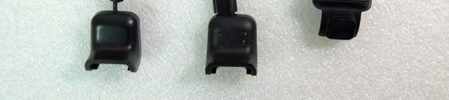

40 Page: 40 of 51 All View of EUT Front View of EUT

41 Page: 41 of 51 Back View of EUT Side View of EUT 1


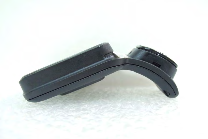
42 Page: 42 of 51 Side View of EUT 2 Side View of EUT 3


")
43 Page: 43 of 51 Side View of EUT 4 USB Dock 1(1.0mm)

")


44 Page: 44 of 51 USB Dock 2(1.5mm) Battery


45 Page: 45 of 51 Open View of EUT 1 Open View of EUT 2


46 Page: 46 of 51 Open View of EUT 3 Open View of EUT 4


47 Page: 47 of 51 Internal View of EUT 1 Internal View of EUT 2


48 Page: 48 of 51 Internal View of EUT 3 Internal View of EUT 4

49 Page: 49 of 51 Internal View of EUT 5 Internal View of EUT 6

50 Page: 50 of 51 Internal View of EUT 7 Internal View of EUT 8


51 Page: 51 of 51 Antenna-BT4.0 Antenna-GPS ~ End of Report ~
CE Test Report. : Microchip Technology Inc. 2355 West Chandler Blvd., Chandler, Arizona 85224-6199, USA
 CE Test Report Equipment : IEEE 802.11b/g Wireless LAN module Brand Name : MICROCHIP Model No. : MRF24WG0MA/MB Standard : EN 300 328 V1.8.1 (2012-06) Operating Band : 2400 MHz 2483.5 MHz Applicant Manufacturer
ETSI EN 300 328-1 V1.2.2 (2000-07)
") EN 300 328-1 V1.2.2 (2000-07) European Standard (Telecommunications series) Electromagnetic compatibility and Radio spectrum Matters (ERM); Wideband Transmission systems; data transmission equipment operating
EN 300 328-1 V1.2.2 (2000-07) European Standard (Telecommunications series) Electromagnetic compatibility and Radio spectrum Matters (ERM); Wideband Transmission systems; data transmission equipment operating
TEST REPORT FROM RFI GLOBAL SERVICES LTD
 FROM RFI GLOBAL SERVICES LTD Partial Test of: BTM411 To: EN 300 328 V1.7.1 (2006-10) Test Report Serial No: RFI/RPT1/RP76018JD01A This Test Report Is Issued Under The Authority Of Brian Watson, Operations
CE Test Report. : BL600 Series Bluetooth Low Energy Module
 CE Test Report Equipment Brand Name Model No. : BL600 Series Bluetooth Low Energy Module : Laird Technologies : BL600-SA, BL600-SC, BL600-ST Additional Model No. : BL620-SA, BL620-SC, BL620-ST Standard
RADIO TEST REPORT. EN 300 440-2 SRD radio equipment to be used in the 1 GHz to 40 GHz frequency range. DAkkS - Registration number : D-PL-12092-01-01
 RADIO TEST REPORT SRD radio equipment to be used in the 1 GHz to 40 GHz frequency range Report Reference No.... : G0M-1206-2043-TEU440G-V01 Testing Laboratory... : Eurofins Product Service GmbH Address...
ETSI EN 300 328 V1.8.1 (2012-06)
") EN 300 328 V1.8.1 (2012-06) Harmonized European Standard Electromagnetic compatibility and Radio spectrum Matters (ERM); Wideband transmission systems; Data transmission equipment operating in the 2,4
EN 300 328 V1.8.1 (2012-06) Harmonized European Standard Electromagnetic compatibility and Radio spectrum Matters (ERM); Wideband transmission systems; Data transmission equipment operating in the 2,4
AN1200.04. Application Note: FCC Regulations for ISM Band Devices: 902-928 MHz. FCC Regulations for ISM Band Devices: 902-928 MHz
 AN1200.04 Application Note: FCC Regulations for ISM Band Devices: Copyright Semtech 2006 1 of 15 www.semtech.com 1 Table of Contents 1 Table of Contents...2 1.1 Index of Figures...2 1.2 Index of Tables...2
ETSI EN 300 328 V1.7.1 (2006-10)
") EN 300 328 V1.7.1 (2006-10) Harmonized European Standard (Telecommunications series) Electromagnetic compatibility and Radio spectrum Matters (ERM); Wideband transmission systems; Data transmission equipment
EN 300 328 V1.7.1 (2006-10) Harmonized European Standard (Telecommunications series) Electromagnetic compatibility and Radio spectrum Matters (ERM); Wideband transmission systems; Data transmission equipment
Application Note AN-00126
 Considerations for Operation within the 902-928MHz Band Application Note AN-00126 Introduction This application note is designed to give the reader a basic understanding of the legal and technical considerations
ETSI EN 302 774 V1.2.1 (2012-02)
") EN 302 774 V1.2.1 (2012-02) Harmonized European Standard Broadband Wireless Access Systems (BWA) in the 3 400 MHz to 3 800 MHz frequency band; Base Stations; Harmonized EN covering the essential requirements
EN 302 774 V1.2.1 (2012-02) Harmonized European Standard Broadband Wireless Access Systems (BWA) in the 3 400 MHz to 3 800 MHz frequency band; Base Stations; Harmonized EN covering the essential requirements
ETSI EN 300 328-2 V1.1.1 (2000-07)
") EN 300 328-2 V1.1.1 (2000-07) Candidate Harmonized European Standard (Telecommunications series) Electromagnetic compatibility and Radio spectrum Matters (ERM); Wideband Transmission systems; data transmission
EN 300 328-2 V1.1.1 (2000-07) Candidate Harmonized European Standard (Telecommunications series) Electromagnetic compatibility and Radio spectrum Matters (ERM); Wideband Transmission systems; data transmission
TCB Workshop. Unlicensed National Information Infrastructure Devices (U-NII)/Dynamic Frequency Selection (DFS)
/Dynamic Frequency Selection (DFS)") 1 TCB Workshop Unlicensed National Information Infrastructure Devices (U-NII)/Dynamic Frequency Selection (DFS) Andrew Leimer Office of Engineering and Technology/Equipment Authorization Branch FCC Laboratory
1 TCB Workshop Unlicensed National Information Infrastructure Devices (U-NII)/Dynamic Frequency Selection (DFS) Andrew Leimer Office of Engineering and Technology/Equipment Authorization Branch FCC Laboratory
RF Exposure Evaluation Report
 RF Exposure Evaluation Report APPLICANT EQUIPMENT BRAND NAME MODEL NAME FCC ID FILING TYPE : TomTom International BV : GPS Navigation System : TomTom : 4CR51 : S4L4CR51 : Certification STANDARD : OET Bulletin
TEST REPORT EN 55014-2 (1997) +A1 (2001)
 +A1 (2001)") Page 1 of 23 TEST REPORT EN 55014-2 (1997) +A1 (2001) Electromagnetic compatibility - Requirements for household appliances, electric tools and similar apparatus Part 2: Immunity Report Reference No....
Page 1 of 23 TEST REPORT EN 55014-2 (1997) +A1 (2001) Electromagnetic compatibility - Requirements for household appliances, electric tools and similar apparatus Part 2: Immunity Report Reference No....
EN 301 489-17 v1.2.1 TEST REPORT FOR. 802.11ag/Draft 802.11n WLAN PCI-E Mini Card MODEL NUMBER: BCM94322MC REPORT NUMBER: 07U11529-5
 EN 301 489-17 v1.2.1 TEST REPORT FOR 802.11ag/Draft 802.11n WLAN PCI-E Mini Card MODEL NUMBER: BCM94322MC REPORT NUMBER: 07U11529-5 ISSUE DATE: JANUARY 29, 2008 Prepared for BROADCOM CORPORATION 190 MATHILDA
Electromagnetic Compatibility Test Report Test results of Floww equipment
 Electromagnetic Compatibility Test Report Test results of Floww equipment Reference number Status test report Brand Model number : 10C00357RPT01.doc : Final : Floww : mobilefloww screenfloww pocketfloww
FCC PART 15B CLASS A MEASUREMENT AND TEST REPORT
 FCC PART 15B CLASS A MEASUREMENT AND TEST REPORT For SAMBO HI TECH CO., LTD. 616-15, GANSUK4-DONG, NAMDONG-GU, INCHUN 405-810, KOREA Model: LSR700, SCI545HV1EF, SCI545HVEF This Report Concerns: Original
Dynamic Frequency Selection (DFS) and the 5GHz Unlicensed Band
 and the 5GHz Unlicensed Band") Dynamic Frequency Selection (DFS) and the 5GHz Unlicensed Band by Mark Briggs, Principal Engineer, Elliott Laboratories- An NTS Company Note: This article combines the content from several papers released
Dynamic Frequency Selection (DFS) and the 5GHz Unlicensed Band by Mark Briggs, Principal Engineer, Elliott Laboratories- An NTS Company Note: This article combines the content from several papers released
AN437. Si4432 RF PERFORMANCE AND FCC COMPLIANCE TEST RESULTS. 1. Introduction. 2. Relevant Measurements to comply with FCC
 Si4432 RF PERFORMANCE AND FCC COMPLIANCE TEST RESULTS 1. Introduction This document provides measurement results and FCC compliance results for the Si4432B when operated from 902 928 MHz. The measurement
FCC PART 15 SUBPART C EMI MEASUREMENT AND TEST REPORT
 FCC PART 15 SUBPART C EMI MEASUREMENT AND TEST REPORT For AeroComm, Inc. 10981 Eicher Drive Lenexa, KS 66219 2003-05-22 This Report Concerns: Original Report Equipment Type: 900MHz Transceiver Test Engineer:
Application Note AN-00125
 Considerations for Operation within the 260 470MHz Band Introduction This application note is designed to give the reader a basic understanding of the legal and technical considerations for operation of
WIRELESS MAGNETIC CONTACT
 WIRELESS MAGNETIC CONTACT The magnetic contact wireless MAG HCS is a sensor able to detect opening or closing doors or windows and transmits via radio a alarm signal. It is composed of two distinct elements:
Rated Power(W) 8W 2. EG-LED0840-01 8W 3. EG-LED1027-01 10W
 8W 2. EG-LED0840-01 8W 3. EG-LED1027-01 10W") 14713221 001 Seite 2 von 37 Page 2 of 37 Model List: No Model Rated Voltage(V) 1. EG-LED0827-01 Rated Power(W) 8W 2. EG-LED0840-01 8W 3. EG-LED1027-01 10W 4. EG-LED1040-01 AC 100-240V, 10W 5. EG-LED1027-02
14713221 001 Seite 2 von 37 Page 2 of 37 Model List: No Model Rated Voltage(V) 1. EG-LED0827-01 Rated Power(W) 8W 2. EG-LED0840-01 8W 3. EG-LED1027-01 10W 4. EG-LED1040-01 AC 100-240V, 10W 5. EG-LED1027-02
Final draft ETSI EN 300 220-1 V2.4.1 (2012-01)
") Final draft EN 300 220-1 V2.4.1 (2012-01) European Standard Electromagnetic compatibility and Radio spectrum Matters (ERM); Short Range Devices (SRD); Radio equipment to be used in the 25 MHz to 1 000
Final draft EN 300 220-1 V2.4.1 (2012-01) European Standard Electromagnetic compatibility and Radio spectrum Matters (ERM); Short Range Devices (SRD); Radio equipment to be used in the 25 MHz to 1 000
Test result: SHENZHEN TIMEWAY TECHNOLOGY CONSULTING CO LTD. ISO/IEC17025Accredited Lab. Report No: FCC 1106180 File reference No: 2011-07-18
 Report No: FCC 1106180 File reference No: 2011-07-18 ISO/IEC17025Accredited Lab. Applicant: FUJIAN NAN AN BAOFENG ELECTRONICS CO., LTD Product: Model No: Trademark: Two Way Radio UV-3R BAOFENG Test Standards:
Nigerian Communications Commission
 Nigerian Communications Commission REGULATORY GUIDELINES FOR THE USE OF 2.4 GHz ISM BAND FOR COMMERCIAL TELECOM SERVICES Introduction The use of broadband for last mile access or for final distribution
TECHNICAL SPECIFICATION FOR CORDLESS TELEPHONE SYSTEMS
 TECHNICAL SPECIFICATION FOR CORDLESS TELEPHONE SYSTEMS Suruhanjaya Komunikasi dan Multimedia Malaysia Off Pesiaran Multimedia, 63000 Cyberjaya, Selangor Darul Ehsan, Malaysia Copyright of SKMM, 2007 FOREWORD
Measurement of RF Emissions from a Final Coat Electronics Corrosion Module
 Engineering Test Report No. 37802-02 Rev. A Measurement of RF Emissions from a Final Coat Electronics Corrosion Module For : Canadian Auto Preservation, Inc. 390 Bradwick Drive Concord, Ontario CANADA
Dynamic Frequency Selection Requirements
 Elliott Laboratories Presents Dynamic Frequency Selection Requirements An overview of radar detection requirements for wireless devices operating in the 5 GHz band (with emphasis on the new FCC rules)
FCC Test Report. FCC Part 22, 24 / RSS 132, 133 FOR: GSM Cellular Telephone with Bluetooth and WiFi. Model #: A1203
 FCC Test Report FCC Part 22, 24 / RSS 132, 133 FOR: GSM Cellular Telephone with Bluetooth and WiFi Model #: A1203 Apple Inc. 1 Infinite Loop Mail Stop26A Cupertino, California 95014 U.S.A FCC ID: BCGA1203
ETSI EN 301 893 V1.7.1 (2012-06)
") EN 301 893 V1.7.1 (2012-06) Harmonized European Standard Broadband Radio Access Networks (BRAN); 5 GHz high performance RLAN; Harmonized EN covering the essential requirements of article 3.2 of the R&TTE
EN 301 893 V1.7.1 (2012-06) Harmonized European Standard Broadband Radio Access Networks (BRAN); 5 GHz high performance RLAN; Harmonized EN covering the essential requirements of article 3.2 of the R&TTE
User manual BETSO WTCS. 16 channel wireless digital TC slate. 1 Copyright BETSO ELECTRONICS Ltd.
 16 channel wireless digital TC slate 1 Copyright BETSO ELECTRONICS Ltd. Contents 1. Product description...3 2. Top features...3 3. Control elements...4 4. Insertion of batteries / accumulators...6 5. External
Regulatory requirements - USA
 Regulatory requirements - USA FCC CFR 47 Part 2 & 15 Radiospectrum and EMF Test on qualified laboratory Test methods different from EU Certification required TCB or FCC Grant Regulatory EMC requirements
USB Plus+ RFID Reader Setup Guide
 875-0042-03 RevA USB Plus+ RFID Reader Setup Guide 1 Government Limited Rights Notice: All documentation and manuals were developed at private expense and no part of it was developed using Government funds.
Design and Certification of ASH Radio Systems for Japan
 Design and Certification of ASH Radio Systems for Japan RFM s second-generation ASH radio hybrids are being used in a wide variety of applications in Japan, operating under the Japanese BIJAKU radio regulations.
MYRICOM, INC. TEST REPORT FOR THE SERVER RACK, 10G-PCIE2-8B2-2S & 10G-PCIE2-8B2-2QP FCC PART 15 SUBPART B SECTIONS 15.107 AND 15.109 CLASS A TESTING
 TESTING CERT #803.01, 803.02, 803.05, 803.06 MYRICOM, INC. TEST REPORT FOR THE SERVER RACK, 10G-PCIE2-8B2-2S & 10G-PCIE2-8B2-2QP FCC PART 15 SUBPART B SECTIONS 15.107 AND 15.109 CLASS A TESTING DATE OF
Report Of. Shielding Effectiveness Test For. SafeSleeve Radiation Shielding Technology. Test Date(s): June 07 June 09, 2015
: June 07 June 09, 2015") Report Of Shielding Effectiveness Test For SafeSleeve Radiation Shielding Technology Test Date(s): June 07 June 09, 2015 Issue Date: June 10, 2015 UST Project No: 15-0137 Total Number of Pages Contained
Report Of Shielding Effectiveness Test For SafeSleeve Radiation Shielding Technology Test Date(s): June 07 June 09, 2015 Issue Date: June 10, 2015 UST Project No: 15-0137 Total Number of Pages Contained
NI USB-5681 RF Power Meter Specifications
 NI USB-568 RF Power Meter Specifications General This document lists specifications for the NI USB-568 RF power meter. Minimum or maximum specifications are warranted under the following conditions: hour
Partial GSM TEST - REPORT
 EUROFINS PRODUCT SERVICE GMBH Partial GSM TEST - REPORT EN 301 511 GSM/GPRS/GPS tracking unit FOX-LT-IP Test report no.: G0M20904-2307-T-51 Eurofins Product Service GmbH Storkower Str. 38c, 15526 Reichenwalde,
ELETRONIC COMMUNICATIONS COMMITTEE
 ELETRONIC COMMUNICATIONS COMMITTEE ECC Decision of 19 March 2004 on harmonised frequencies, technical characteristics and exemption from individual licensing of Non-specific Short Range Devices operating
TECHNICAL SPECIFICATION FOR GSM MOBILE TERMINALS
 TECHNICAL SPECIFICATION FOR GSM MOBILE TERMINALS Suruhanjaya Komunikasi dan Multimedia Malaysia Off Pesiaran Multimedia, 63000 Cyberjaya, Selangor Darul Ehsan, Malaysia Copyright of SKMM, 2007 FOREWORD
Field Calibration Software
 SIGNAL HOUND Field Calibration Software User s Manual Version 1.1.0 7/8/2016 This information is being released into the public domain in accordance with the Export Administration Regulations 15 CFR 734
UK Radio Licence Interface Requirement 2036 For Mobile Asset Tracking Services
 UK Radio Licence Interface Requirement 2036 For Mobile Asset Tracking Services (Version 1.0) 98/34/EC Notification Number: 2000/393/UK Published 15 December 2000 Page 1 File name: ir2036.doc Blank Page
Draft ETSI EN 301 783-1 V1.2.1 (2009-07)
") Draft EN 301 783-1 V1.2.1 (2009-07) European Standard (Telecommunications series) Electromagnetic compatibility and Radio spectrum Matters (ERM); Land Mobile Service; Commercially available amateur radio
Draft EN 301 783-1 V1.2.1 (2009-07) European Standard (Telecommunications series) Electromagnetic compatibility and Radio spectrum Matters (ERM); Land Mobile Service; Commercially available amateur radio
RX-AM4SF Receiver. Pin-out. Connections
 RX-AM4SF Receiver The super-heterodyne receiver RX-AM4SF can provide a RSSI output indicating the amplitude of the received signal: this output can be used to create a field-strength meter capable to indicate
SmartDiagnostics Application Note Wireless Interference
 SmartDiagnostics Application Note Wireless Interference Publication Date: May 27, 2015 KCF Technologies, Inc. Background The SmartDiagnostics wireless network is an easy to install, end-to-end machine
Test Report. DAB+ Automotive OEM Receiver. Nasjonal kommunikasjonsmyndighet Nygård 1, Postboks 93 4791 Lillesand, Norway
 Report No. 298328-3 Test Report Product Name and address of the applicant Name and address of the manufacturer DAB+ Automotive OEM Receiver Nasjonal kommunikasjonsmyndighet Nygård 1, Postboks 93 4791 Lillesand,
GSM Voice Auto Dialer & SMS Sender JC-999
 GSM Voice Auto Dialer & SMS Sender JC-999 Main features: () Large LCD display,integrated integrated keypad, human-friendly programming; (2) Support 2 alarm receiving numbers; (3) Triggering means: N.C
Characteristics of terrestrial IMT-Advanced systems for frequency sharing/ interference analyses
 Report ITU-R M.2292-0 (12/2013) Characteristics of terrestrial IMT-Advanced systems for frequency sharing/ interference analyses M Series Mobile, radiodetermination, amateur and related satellite services
EMC Basics. Speaker : Alain Lafuente. [email protected]
 EMC Basics Speaker : lain Lafuente [email protected] WHT IS EMC? 2 CE Marking With the formation of the single European market, standardization was required to remove technical barriers to trade.
ETSI EN 301 893 V1.8.1 (2015-03)
") EN 301 893 V1.8.1 (2015-03) HARMONIZED EUROPEAN STANDARD Broadband Radio Access Networks (BRAN); 5 GHz high performance RLAN; Harmonized EN covering the essential requirements of article 3.2 of the R&TTE
EN 301 893 V1.8.1 (2015-03) HARMONIZED EUROPEAN STANDARD Broadband Radio Access Networks (BRAN); 5 GHz high performance RLAN; Harmonized EN covering the essential requirements of article 3.2 of the R&TTE
FCC RF Exposure Report
 FCC RF Exposure Report FCC ID Equipment Model No. Brand Name Applicant : SQGBT800 : BTv4.0 Dual Mode USB Dongle : BT820 : Laird Technologies : Laird Technologies Address : 11160 Thompson Ave. / Lenexa,
Application Note AN001
 AN001 SRD regulations for licence free transceiver operation By P. M. Evjen Keywords CEPT recommendations ETSI standards R&TTE directive Part 15 devices Type approval Equipment testing Operating frequency
How To Write An En 302 245-1 V1.1.2
 EN 302 245-1 V1.1.1 (2005-01) European Standard (Telecommunications series) Electromagnetic compatibility and Radio spectrum Matters (ERM); Transmitting equipment for the Digital Radio Mondiale (DRM) broadcasting
Small Entity Compliance Guide
 Federal Communications Commission Washington, D.C. 20554 April 18, 2013 DA 13-791 Small Entity Compliance Guide Operation of Unlicensed Personal Communications Service Devices in the 1920-1930 MHz Band
MSAN-001 X-Band Microwave Motion Sensor Module Application Note
 1. Introduction HB Series of microwave motion sensor module are X-Band Mono-static DRO Doppler transceiver front-end module. These modules are designed for movement detection, like intruder alarms, occupancy
II. Radio equipment which transmits only under the control of electronic communications networks
 LIST of radio equipment using frequency bands harmonised throughout the EU and electronic communications terminal equipment I. Electronic communications terminal equipment intended for connection to the
Bluetooth to Serial Adapter
 Bluetooth to Serial Adapter Third Edition, Oct 2007 Version 3.0 771-BTS1009C3-001 Contents 1.0 Features....P.2 2.0 Package Content....P.2 3.0 Hard Drives Requirement.P.2 4.0 Specifications.P.3 5.0 Pin
Monitores Equipos Móviles Especificaciones de Producto
 EquipManager -4 F/-20 C to +140 F/+60 C (optional heater available for cold room applications) 0 100% noncondensing User-adjustable threshold 0.3G to 7G 10G (nondestructive)/100g (destructive) Piezoelectric
ETSI EN 301 489-17 V2.1.1 (2009-05) Harmonized European Standard (Telecommunications series)
 Harmonized European Standard (Telecommunications series)") EN 301 489-17 V2.1.1 (2009-05) Harmonized European Standard (Telecommunications series) Electromagnetic compatibility and Radio spectrum Matters (ERM); ElectroMagnetic Compatibility (EMC) standard for
EN 301 489-17 V2.1.1 (2009-05) Harmonized European Standard (Telecommunications series) Electromagnetic compatibility and Radio spectrum Matters (ERM); ElectroMagnetic Compatibility (EMC) standard for
Safety Warnings and Guidelines
 Safety Warnings and Guidelines Thank you for purchasing this Wireless Speaker Amplifier! For best results, please thoroughly read this manual and carefully follow the instructions. Please pay extra attention
MOBILE PHONE REPEATERS
 Group of Administrative Co-operation Under the R&TTE Directive 6 th R&TTE Market Surveillance Campaign on Mobile Phone Repeaters REPORT ON THE 6 TH JOINT CROSS-BORDER R&TTE MARKET SURVEILLANCE CAMPAIGN
FM TRANSMITTER & RECEIVER HYBRID MODULES. FM-RTFQ SERIES FM-RRFQ SERIES. Transmitter. Receiver. Applications
 FM Radio Transmitter & Receivers Available as or or 868MHz Transmit Range up to 20m Miniature Packages Data Rate up to 9.6Kbps No Adjustable Components Very Stable Operating Frequency Operates from 20
ES-3305P V2 / ES-3308P V2. Quick Installation Guide. 09-2013 / v1.0
 ES-3305P V2 / ES-3308P V2 Quick Installation Guide 09-2013 / v1.0 1 COPYRIGHT Copyright Edimax Technology Co., Ltd. all rights reserved. No part of this publication may be reproduced, transmitted, transcribed,
FM TRANSMITTER & RECEIVER HYBRID MODULES. FM-RRFQ SERIES. Transmitter. Receiver. Applications
 FM Radio Transmitter & Receivers Available As or or 88MHz Transmit Range Up To 0m Miniature Packages Data Rate upto 9.Kbps No Adjustable Components Very Stable Operating Frequency Operates from 0 to +8
LTE Evolution for Cellular IoT Ericsson & NSN
 LTE Evolution for Cellular IoT Ericsson & NSN LTE Evolution for Cellular IoT Overview and introduction White Paper on M2M is geared towards low cost M2M applications Utility (electricity/gas/water) metering
Ultra Wideband Signal Impact on IEEE802.11b Network Performance
 Ultra Wideband Signal Impact on IEEE802.11b Network Performance Matti Hämäläinen 1, Jani Saloranta 1, Juha-Pekka Mäkelä 1, Tero Patana 2, Ian Oppermann 1 1 Centre for Wireless Communications (CWC), University
RECOMMENDATION ITU-R SM.1792. Measuring sideband emissions of T-DAB and DVB-T transmitters for monitoring purposes
 Rec. ITU-R SM.1792 1 RECOMMENDATION ITU-R SM.1792 Measuring sideband emissions of T-DAB and DVB-T transmitters for monitoring purposes (2007) Scope This Recommendation provides guidance to measurement
Remarkable achievements
 Remarkable achievements 149.2 km link over water providing 8E1 throughput with 99,99% annual availability Radio link transmitting data from 25km height in Stratosphere to 149km ground station Largest MW
SR450 RECEIVER OPERATING INSTRUCTIONS 1892 1128
 SR450 RECEIVER OPERATING INSTRUCTIONS 1892 1128 These operating instructions are intended to provide the user with sufficient information to install and operate the module correctly. The Wood & Douglas
802.11ac Power Measurement and Timing Analysis
 802.11ac Power Measurement and Timing Analysis Using the 8990B Peak Power Analyzer Application Note Introduction There are a number of challenges to anticipate when testing WLAN 802.11ac [1] power amplifier
WIRELESS INSTRUMENTATION TECHNOLOGY
 BS&B WIRELESS, L.L.C. BS&B WIRELESS, L.L.C. WIRELESS INSTRUMENTATION TECHNOLOGY Printed February 2004 BS&B WIRELESS, L.L.C. 7422-B East 46th Place, Tulsa, OK74145 Phone: 918-622-5950 Fax: 918-665-3904
Guangzhou HC Information Technology Co., Ltd. Product Data Sheet
 Guangzhou HC Information Technology Co., Ltd. Product Data Sheet Module Data Sheet Rev 1 1.0 1.01 2010/5/15 2011/4/6 DRAWN BY : Ling Xin MODEL : HC-05 CHECKED BY : Eric Huang Description: BC04 has external
Guangzhou HC Information Technology Co., Ltd. Product Data Sheet
 Guangzhou HC Information Technology Co., Ltd. Product Data Sheet Module Data Sheet Rev 1 1.0 1.01 2010/5/15 2011/4/6 DRAWN BY : Ling Xin MODEL : HC-05 CHECKED BY : Eric Huang Description: BC04 has external
98/34/EC Notification Number: 2001/0326/UK
 UK Radio Interface Requirement 2041 for Broadband Fixed Wireless Access Point--Point Radio Systems in the 28 GHz Frequency Band Administered by the Radiocommunications Agency (Version 4.0) 98/34/EC Notification
Quick Start Guide. MRB-KW01 Development Platform Radio Utility Application Demo MODULAR REFERENCE BOARD
 Quick Start Guide MRB-KW01 Development Platform Radio Utility Application Demo MODULAR REFERENCE BOARD Quick Start Guide Get to Know the MRB-KW01x Module UART Selector ANT 1 RFIO (TX/RX) USB 2.0 Serial
Impedance 50 (75 connectors via adapters)
") VECTOR NETWORK ANALYZER PLANAR TR1300/1 DATA SHEET Frequency range: 300 khz to 1.3 GHz Measured parameters: S11, S21 Dynamic range of transmission measurement magnitude: 130 db Measurement time per point:
VECTOR NETWORK ANALYZER PLANAR TR1300/1 DATA SHEET Frequency range: 300 khz to 1.3 GHz Measured parameters: S11, S21 Dynamic range of transmission measurement magnitude: 130 db Measurement time per point:
OpenWay Radio Frequency FAQ
 OpenWay Radio Frequency FAQ March 10, 2010 2010, Itron Inc. All rights reserved. 1 Overview This document provides general information about radiofrequency (RF) electromagnetic fields from OpenWay wireless
STANDARDS TO ACCESS AND OPERATE SATELLITE SERVICES
 STANDARDS TO ACCESS AND OPERATE SATELLITE SERVICES INDEX I. Scope... 3 II. Bandwidth and Power Standards... 3 A. Bandwidth (BW) Allocation and Measurement... 3 1. Bandwidth of a digital carrier per customer....
FCC RF Exposure Report
 FCC RF Exposure Report FCC ID Equipment Model No. Brand Name Applicant : SQGBT900 : Bluetooth Dual Mode UART AT featuring smartbasic : BT900-SA, BT900-SC (please refer to 1.1.1 for more details.) : Laird
Test Report. Prepared for: Technologic Systems, Inc. Model: TS-8820
 Test Report Prepared for: Technologic Systems, Inc. Model: TS-8820 Description: Single Board Computer with Analog and Digital Inputs and Outputs, Relays, and RS-232/485 Ports To IEC 61000-6-1 (2005-03)
Wharf T&T Limited Report of Wireless LAN Technology Trial Version: 1.0 Date: 26 Jan 2004. Wharf T&T Limited. Version: 1.0 Date: 26 January 2004
 Wharf T&T Limited Version: 1.0 Date: 26 January 2004 This document is the property of Wharf T&T Limited who owns the copyright therein. Without the written consent of Wharf T&T Limited given by contract
iva Cable & Antenna Analyzer
 iva Cable & Antenna Analyzer VSWR, Return Loss Measurement & Distance to Fault The iva Series Cable & Antenna Analyzer is an exciting new product from Kaelus that enables users to accurately measure VSWR/return
Features. Applications. Description. Blockdiagram. K-LC1a RADAR TRANSCEIVER. Datasheet
 Features 24 GHz K-band miniature transceiver 180MHz sweep FM input (n.a. for K-LC1a_V2) Dual 4 patch antenna Single balanced mixer with 50MHz bandwidth Beam aperture 80 /34 15dBm EIRP output power 25x25mm
RECOMMENDATION ITU-R S.524-5. (Questions ITU-R 48/4 and ITU-R 70/4)
") Rec. ITU-R S.524-5 1 RECOMMENDATION ITU-R S.524-5 MAXIMUM PERMISSIBLE LEVELS OF OFF-AXIS e.i.r.p. DENSITY FROM EARTH STATIONS IN THE FIXED-SATELLITE SERVICE TRANSMITTING IN THE 6 AND 14 GHz FREQUENCY BANDS
Rec. ITU-R S.524-5 1 RECOMMENDATION ITU-R S.524-5 MAXIMUM PERMISSIBLE LEVELS OF OFF-AXIS e.i.r.p. DENSITY FROM EARTH STATIONS IN THE FIXED-SATELLITE SERVICE TRANSMITTING IN THE 6 AND 14 GHz FREQUENCY BANDS
TECHNICAL SPECIFICATION FOR BROADBAND WIRELESS ACCESS (BWA) EQUIPMENT
 EQUIPMENT") TECHNICAL SPECIFICATION FOR BROADBAND WIRELESS ACCESS (BWA) EQUIPMENT Suruhanjaya Komunikasi dan Multimedia Malaysia Off Pesiaran Multimedia, 63000 Cyberjaya, Selangor Darul Ehsan, Malaysia Copyright of
TECHNICAL SPECIFICATION FOR BROADBAND WIRELESS ACCESS (BWA) EQUIPMENT Suruhanjaya Komunikasi dan Multimedia Malaysia Off Pesiaran Multimedia, 63000 Cyberjaya, Selangor Darul Ehsan, Malaysia Copyright of
COMMON REGULATORY OBJECTIVES FOR WIRELESS LOCAL AREA NETWORK (WLAN) EQUIPMENT PART 2 SPECIFIC ASPECTS OF WLAN EQUIPMENT
 EQUIPMENT PART 2 SPECIFIC ASPECTS OF WLAN EQUIPMENT") COMMON REGULATORY OBJECTIVES FOR WIRELESS LOCAL AREA NETWORK (WLAN) EQUIPMENT PART 2 SPECIFIC ASPECTS OF WLAN EQUIPMENT 1. SCOPE This Common Regulatory Objective, CRO, is applicable to Wireless Local Area
COMMON REGULATORY OBJECTIVES FOR WIRELESS LOCAL AREA NETWORK (WLAN) EQUIPMENT PART 2 SPECIFIC ASPECTS OF WLAN EQUIPMENT 1. SCOPE This Common Regulatory Objective, CRO, is applicable to Wireless Local Area
iva Cable & Antenna Analyzer
 iva Cable & Antenna Analyzer VSWR, Return Loss Measurement & Distance to Fault The iva Series Cable & Antenna Analyzer is an exciting new product from Kaelus that enables users to accurately measure VSWR/return
ETSI EN 302 567 V1.2.1 (2012-01)
") EN 302 567 V1.2.1 (2012-01) Harmonized European Standard Broadband Radio Access Networks (BRAN); 60 GHz Multiple-Gigabit WAS/RLAN Systems; Harmonized EN covering the essential requirements of article 3.2
EN 302 567 V1.2.1 (2012-01) Harmonized European Standard Broadband Radio Access Networks (BRAN); 60 GHz Multiple-Gigabit WAS/RLAN Systems; Harmonized EN covering the essential requirements of article 3.2
R&S R-Line Compact Test Chamber Precise measurements of radiated emissions of wireless terminals 800 MHz to 18 GHz
 Test & Measurement Data Sheet 02.00 R&S R-Line Compact Test Chamber Precise measurements of radiated emissions of wireless terminals 800 MHz to 18 GHz R&S R-Line Compact Test Chamber At a glance The R-Line
Chapter 6 Bandwidth Utilization: Multiplexing and Spreading 6.1
 Chapter 6 Bandwidth Utilization: Multiplexing and Spreading 6.1 Copyright The McGraw-Hill Companies, Inc. Permission required for reproduction or display. Note Bandwidth utilization is the wise use of
INTRODUCTION TO COMMUNICATION SYSTEMS AND TRANSMISSION MEDIA
 COMM.ENG INTRODUCTION TO COMMUNICATION SYSTEMS AND TRANSMISSION MEDIA 9/6/2014 LECTURES 1 Objectives To give a background on Communication system components and channels (media) A distinction between analogue
R&S ZNC Vector Network Analyzer Specifications
 ZNC3_dat-sw_en_5214-5610-22_v0300_cover.indd 1 Data Sheet 03.00 Test & Measurement R&S ZNC Vector Network Analyzer Specifications 04.09.2012 13:39:47 CONTENTS Definitions... 3 Measurement range... 4 Measurement
RECOMMENDATION ITU-R M.1453-1 * Transport information and control systems Dedicated short range communications at 5.8 GHz
 Rec. ITU-R M.1453-1 1 RECOMMENDATION ITU-R M.1453-1 * Transport and control systems Dedicated short range communications at 5.8 GHz (Question ITU-R 205/8) (2000-2002) The ITU Radiocommunication Assembly,
ECC/DEC/(04)08 ELECTRONIC COMMUNICATIONS COMMITTEE
08 ELECTRONIC COMMUNICATIONS COMMITTEE") ELECTRONIC COMMUNICATIONS COMMITTEE ECC Decision of 09 July 2004 on the harmonised use of the 5 GHz frequency bands for the implementation of Wireless Access Systems including Radio Local Area Networks
ELECTRONIC COMMUNICATIONS COMMITTEE ECC Decision of 09 July 2004 on the harmonised use of the 5 GHz frequency bands for the implementation of Wireless Access Systems including Radio Local Area Networks
'Possibilities and Limitations in Software Defined Radio Design.
 'Possibilities and Limitations in Software Defined Radio Design. or Die Eierlegende Wollmilchsau Peter E. Chadwick Chairman, ETSI ERM_TG30, co-ordinated by ETSI ERM_RM Software Defined Radio or the answer
Radio Frequency Exposure Test Report
 Radio Frequency Exposure EN 62311 January 2008 Assessment of electronic and electrical equipment related to human exposure restrictions for electromagnetic fields (0Hz 300GHz) (IEC 62311:2007, modified)