USER S M MANUAL. Variable LED Hemispherical Imager. RIT Multidisciplinary Senior Design. May, 2011
|
|
|
- Melanie McBride
- 7 years ago
- Views:
Transcription

1 U USER S M MANUAL Variable LED Hemispherical Imager RIT Multidisciplinary Senior Design May, 2011
2 Revision Sheet Revision Sheet Release No. Date Revision Description Rev. 0 5/01/11 User s Manual User s Manual
3 USER'S MANUAL TABLE OF CONTENTS Page # 1.0 GENERAL INFORMATION System Overview Project References Organization of the Manual Acronyms and Abbreviations USING THE SYSTEM (MAC) Arduino Configuration Driver Installation MAC OS X Board/Serial Port Selection MATLAB IO Package Upload USING THE SYSTEM (PC) Arduino Configuration Driver Installation MAC OS X Board/Serial Port Selection MATLAB IO Package Upload MATLAB ARDUINO USAGE Arduino Configuration DomeInit DomeSet DomeClose
4 1.0 General Information 1.0 GENERAL INFORMATION User s Manual
5 1.0 General Information 1.0 GENERAL INFORMATION 1.1 System Overview The many forms of LEDs are the emerging technology for illumination. Fundamental evaluation and quantification of image appearance as a function of illumination spectrum, intensity, and. incident angles require a tunable light source. An illumination cavity consisting of a 1 meter diameter hemisphere is required. The design of the hemisphere enables repeatable positioning of LED clusters. The LED cluster consist of 1-7 LEDs mounted in a repeatable manner to maximize additivity of output. The microcontroller being used in this project is the Arduino Duemilanove. It interfaces with MATLAB to control the outer 6 LEDs of the cluster with an 8-bit output allowing the user to alter the intensity of a desired LED as needed. The 7th LED, usually white and positioned in the middle, can be controlled through a digital pin for an on/off position. Only 6 out of the 7 LEDs have an 8-bit control because each Arduino has 6 PWM outputs. The Arduino also has an additional 8 digital outputs, which allows the white LED to be digitally controlled. As such, a separate microcontroller is needed for each LED cluster. 1.2 Project References Primary Control Designer: Alexander Usachev ( axu1402@rit.edu) Project Team Leader: Nicholas Liotta (nol4939@rit.edu) 1.3 Organization of the Manual General Information MAC Arduino Configuration PC Arduino Configuration MATLAB Arduino Usage 1.4 Acronyms and Abbreviations LED - light emitting diode PWM - pulse-width-modulation User s Manual
6 2.0 Using the System (Online) 2.0 USING THE SYSTEM (MacOSX) User s Manual
7 6.0 Cluster Assembly 2.0 USING THE SYSTEM (MAC) 2.1 Arduino Configuration In order for the MAC to be able to communicate with the Arduino, a FTDI driver needs to be installed. Due to the fact that the Mac OS X operating system assigns a different port name for each Arduino, this driver has to be installed each time a new Arduino is connected to the computer Driver Installation Mac OS X After connecting the Arduino to a desired USB port, copy the attached "arduino-0022.dmg" file to the computer. Double click on this file and you should see the following screen: Open the FTDI driver file and continue through the installation process. This should look something very similar to the process shown below.

8
9 To verify that the driver was installed correctly, type in ls /dev/tty.* or ls /dev/cu.* in the Terminal window. This should give the following responses:
 should go on. Double click the Arduino application.")
10 Make sure you see a line with the text /dev/tty.usbserial-xxxxx where the xxx's can be anything. Same for /dev/cu.usbserial-xxxxx. This indicates that the driver installed properly and that the Arduino was found Board/Serial Port Selection Connect the Arduino board to your computer using the USB cable. The green power LED (labelled PWR) should go on. Double click the Arduino application. You'll need to select the correct board and serial port prior to uploading the MATLAB IO package. To select the board, go to Tools > Board. In a window similar to the one shown below, select Arduino Duemilanove or Nano w/ ATmega328.

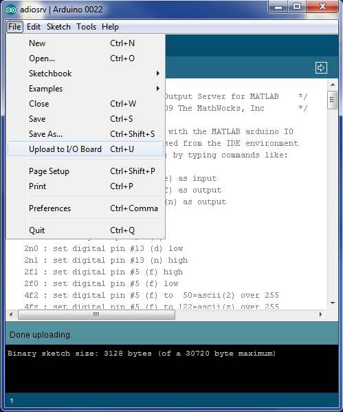
11 To select the serial port, go to Tools > Serial Port, and select the port you saw in the Terminal window after installing the FTDI driver. The window should look similar to the one shown below MATLAB IO Package Upload Go to File > Open, and select the "adiosrv.pde" file included in this package. Now go to File > Upload to I/O Board. Wait a few seconds - you should see the RX and TX LEDs on the board flashing. If the upload is successful, the message "Done uploading." will appear in the status bar. The process is shown in the image below.

12
13 3.0 USING THE SYSTEM (PC)

14 3.0 USING THE SYSTEM (PC) 3.1 Arduino Configuration In order for the PC to be able to communicate with the Arduino, a driver needs to be installed. The driver should only need to be installed once, no matter how many Arduinos are connected Driver Installation Mac OS X After connecting the Arduino to a desired USB port, the driver should be installed automatically on Windows Vista and Windows 7. On Windows XP, and in the case where the driver is not installed, the Add New Hardware wizard will open. If the wizard does not open, go to Start > Settings > Control Panel, and open the wizard manually. When asked Can Windows connect to Windows Update to search for software? select No, not this time. Click next. At the next screen, select Install from a list or specific location.
15 At the next screen make sure Include this location is selected and browse to the arduino-0022/drivers/ location included in this package. It should copy some files and then come up with the window below. Almost immediately, another window will pop up, this time it will say USB Serial Port. As before, click Install from a list or specific location.
16 Browse to the arduino-0022/drivers/ again. The installation should complete successfully. The computer might need to reboot. After it is done rebooting, make sure the Arduino is plugged in (and the green light is lit). Go to the Device Manager (From the Start Menu, select Settings->Control Panel. Double click on System and select the Hardware tab. Then click on the Device Manager button).

17 Look for an entry under Ports (COM & LPT) that says USB Serial Port (COM) the COM number may vary but it should be something like COM3 or COM4. The COM stands for "communication", and each one has a unique number, known as the COM Port number. In this case the COM Port number is COM3. If you don't see the COM port verify the Arduino is plugged in, and check that you installed the VCP FTDI driver Board/Serial Port Selection Connect the Arduino board to your computer using the USB cable. The green power LED (labelled PWR) should go on. Double click the Arduino application. You'll need to select the correct board and serial port prior to uploading the MATLAB IO package. To select the board, go to Tools > Board. In a window similar to the one shown below, select Arduino Duemilanove or Nano w/ ATmega328

18 To select the serial port, go to Tools > Serial Port, and select the port you saw in the Device Manager window after installing the driver. The window should look similar to the one shown below.

19 3.1.3 MATLAB IO Package Upload Go to File > Open, and select the "adiosrv.pde" file included in this package. Now go to File > Upload to I/O Board. Wait a few seconds - you should see the RX and TX LEDs on the board flashing. If the upload is successful, the message "Done uploading." will appear in the status bar. The process is shown in the image below.
20
21 4.0 MATLAB ARDUINO USAGE
22 4.0 MATLAB ARDUINO USAGE 4.1 Arduino Configuration In order for MATLAB to be able to communicate with the Arduino, the "arduino.m" file included in the package must be in the working MATLAB folder. The three functions used to control the Arduino, "DomeInit.m", "DomeSet.m", "DomeClose.m" should also be included in the working folder DomeInit The purpose of the DomeInit function is to instantiate all the Arduinos that will be controlled by MATLAB. The following code shows the DomeInit function for two Arduinos. This code snippet is used in the windows environment. If a MAC OS was used, instead of 'COM4', the code would be something along the lines of '/dev/tty.usbserial-a4001ncf'.
23 The function is called using the syntax "DomeInit([1,2])". The completed code contains all 7 microcontrollers which can be called together or separately using their assigned index. The 'pinmode' commands prepare the associated pins to be used as outputs. Pin 12 is the lone digital output, while 11, 10, 9, 6, 5 and 3 are the PWM outputs. When this command is entered into MATLAB, the user should see this on the screen: DomeSet The DomeSet function sets the intensities of the LEDs of a cluster to the values given. The function takes two parameters, the cluster number, and the array of intensities. The array of intensities contains 7 values, where the first is the on/off switch for the white LED, and 2-6 are the intensities for the 8-bit controlled LEDs. The code below shows the DomeSet function for a system with 2 LED clusters.
24 The value of 'b' differentiates between clusters. 'digitalwrite' is used to control the digital LED while 'analogwrite' is used for the 8-bit controlled LEDs. The following image shows what this command looks like in MATLAB when setting both clusters to the brightest values of all LEDs: DomeClose The DomeClose function disconnects the Arduino from MATLAB. As seen in the code below, which is used for the system with two LED clusters, this function contains one parameter which identifies which LED cluster needs to be closed.
25 The 'delete' method is what disconnects the Arduino from the port it was instantiated with in DomeInit. The DomeClose function is called using a similar syntax to DomeInit, "DomeClose([1,2])", where the parameters specify which clusters to disconnect. This is what it looks like in MATLAB:
26 5.0 4V GEODESIC DOME ASSEMBLY
 iii. Type C (Quantity: 60 units) iv. Type D (Quantity: 70 units) v. Type E (Quantity: 30 units) vi. Type F (Quantity: 30 units) 2. Bolts and corresponding nuts i.")
27 5.0 4V GEODESIC DOME ASSEMBLY 5.1 Required Materials The following materials are required for proper assembly of the 4V geodesic dome: 1. Struts i. Type A (Quantity: 30 units) ii. Type B (Quantity: 30 units) iii. Type C (Quantity: 60 units) iv. Type D (Quantity: 70 units) v. Type E (Quantity: 30 units) vi. Type F (Quantity: 30 units) 2. Bolts and corresponding nuts i. ¼-20 (Quantity: 90 each) 3. Hex key or power drill with driver of appropriate size 4. Wrench of appropriate size 5.2 Assembly Instructions Assemble the structure as per the construction map provided below. It is recommended to either build the dome up from the bottom or down from the top. The dome will not be rigid until each bolt is securely tightened.
28 6.0 CLUSTER ASSEMBLY
29 6.0 Cluster Assembly 6.0 CLUSTER ASSEMBLY 6.1 Machining Turn Cluster Housing Turn the O.D. (outside dimension) of the housing to 1.5 inches and the face length to 1 inch. Drill a halfon top of the cluster inch through-hole. Bore 1 inch hole 0.75 inches deep. Then drill and tap hole pattern housing to hold the reflector (see Drawing). Drill a hole on the side for the cable Turn Reflector Turn the O.D. to 1.5 inches and face length to inches. Drill a hole pattern on the mill and counter- bore a 1-inch hole on one side inches deep.
30 6.0 0 Cluster Assembly Cut PCB Rough cut the PCB on a band saw. Then cut on a mill with a hole saw. Afterwards, grind down the PCB to fit the cluster housing. 6.2 Electrical Assembly Soldering PCB Connectors The PCB connectors must be soldered into the board and this process is performed in two steps. For ease of assembly, the connectors for the ground pat path should be soldered in first. This is done by placing a connector into one of the holes on the PCB, flipping the board over while holding the connector in place, and soldering dering the connector in place. This process is repeated until all paths to ground have a connector attached. The second step of this assembly is to solder the co connectors nnectors for each signal path to the PCB. This can easily be done by placing the connectors into the remaining holes and soldering each in place on the top of the PCB Cable Assembly The cable for this cluster must then be assembled. First, the cable must be cut to the desired length. All current clusters are constructed with a 12 ft long cable, but any cable length can be used as long as it has

31 eight conductors (wires). Each end of the cable should be stripped to expose three to four inches of wires. At one end of the cable, the wires should be individually stripped and the male pins should be crimped in place. To increase durability and reliability, each crimp should be soldered to the wire it is attached to. The connector backing can then be placed onto the cable, to be screwed in place later. The connector can now be attached to the cable. This is performed by inserting the crimped wires into the CPC connector. This can be done one at a time by pushing the crimped wire into the connector pin until a "clicking" sound is heard. This signals that the crimp is inserted far enough to create a secure electrical connection. Each cable contains 8 different colored wires, which were assigned a number that corresponds to a pin number on the connector and a location number on the PCB. The one exception to this convention is that the grey wire is placed in position 8 of the connector and corresponds to the ground connection on the PCB. The combination used in the current clusters is as follows: Connector Pin Number Color of Wire PCB Number 1 Red 1 2 Yellow 2 3 Green 3 4 Brown 4 5 Purple 5 6 Orange 6 7 Blue 7 8 Grey GND Male Connector Female Connector Cable/Cluster Integration Once all crimped wires are inserted into the correct connector pins, the connector backing can be screwed in place, and the strain relief insert can be added. The last step is to solder the cable wires to the PCB. The convention explained above is used to determine which wire is attached to each signal line on the
32 PCB. When all of the wires are soldered in place, the remaining wire slack can be carefully twisted and kept inside the cluster housing to provide additional strain relief. At this point, the PCB can be mounted to the cluster by inserting the three 4-40 screws into every other hole on the cluster. 6.3 Final Cluster Assembly Cable Harness LED Placement The desired LEDs are then chosen and placed into each location on the PCB. Each LED is first marked with a sharpie or paint marker on the cathode (the flat side of the LED casing, with the shorter lead). This is done to denote which side should always be placed onto the ground path of the PCB. If a LED is not oriented in this manner, damage to the LED and/or microcontroller may occur. The leads of the LED are then trimmed to an appropriate length, and are placed onto the PCB in their desired position. The clusters were provided with a standard set of LEDs, with the order provided in the list below: PCB Number LED Color 1 White 2 Orange 3 White 4 Red 5 Green 6 Blue 7 Yellow Reflector Attachment The reflector can then be attached to the cluster housing. This is done by orienting the reflector to tightly fit over the bolts used to attach the PCB, and pressing it in place. Three 4-40 bolts are then used to firmly hold the reflector in place.
, and then all LEDs at once. If everything was properly soldered and assembled, this should occur with no problems.")
33 6.3.3 Testing Once a full assembly of the cluster housing is completed, the cluster must be tested. This can quickly be done by turning each LED on separately (to full intensity), and then all LEDs at once. If everything was properly soldered and assembled, this should occur with no problems. If any LED does not turn on, a few simple steps of basic troubleshooting can be performed. 1. Slightly loosen the bolts connecting the reflector to the cluster housing and perform the test again. Occasionally, too much strain on the cluster will cause a short. 2. Remove the reflector and ensure that all LEDs are placed in the proper orientation. Also ensure that the LED leads are not too short for the PCB connector. 3. If the problem is still present, a digital multimeter can be used to check if there are any shorts on the PCB or within the system Epoxy Work When the cluster passes the fully assembled test, certain components must be epoxied to the cluster housing. Magnets should be epoxied in place on the backside of the cluster housing. The cable entering the side of the cluster housing should also be epoxied in place.
Bluetooth + USB 16 Servo Controller [RKI-1005 & RKI-1205]
![Bluetooth + USB 16 Servo Controller [RKI-1005 & RKI-1205]](/thumbs/40/21161302.jpg "Bluetooth + USB 16 Servo Controller [RKI-1005 & RKI-1205]") Bluetooth + USB 16 Servo Controller [RKI-1005 & RKI-1205] Users Manual Robokits India info@robokits.co.in http://www.robokitsworld.com Page 1 Bluetooth + USB 16 Servo Controller is used to control up to
Bluetooth + USB 16 Servo Controller [RKI-1005 & RKI-1205] Users Manual Robokits India info@robokits.co.in http://www.robokitsworld.com Page 1 Bluetooth + USB 16 Servo Controller is used to control up to
INDEX. Trademarks All name and product s trademarks mentioned below are the property of their respective companies.
 USB2.0 EASY IDE ADAPTER INDEX Trademarks ---------------------------------------------------------------------------- Introduction ---------------------------------------------------------------------------
EPSON Stylus. Start Here
 EPSON Stylus C84 EPSON Stylus Start Here C84 CPD-16675R1 4043482-00 XXX 1 Unpack 1 Remove everything from the box. Paper support Printer Manual Power cord Ink cartridges CD-ROM 2 Remove all the blue tape
IMMS-CCC. IMMS-CCC Hardwire Central Interface. Installation Instructions
 IMMS-CCC IMMS-CCC Hardwire Central Interface Installation Instructions TABLE OF CONTENTS... Choose a Location... 1 Connections... 2 Operations... 3 Software Configuration... 4 Troubleshooting... 5 Loopback
INTRODUCTION TO SERIAL ARM
 INTRODUCTION TO SERIAL ARM A robot manipulator consists of links connected by joints. The links of the manipulator can be considered to form a kinematic chain. The business end of the kinematic chain of
User manual DinaSys DTC/DTS and DTC/DTZ
 PiCommIT has developed the DinaSys DTC/DTS and DinaSys DTC/DTZ turntable controller for the Fleischmann / Marklin Turntables in scale H0, H0m, TT, N and Z. One of the most important starting point was
XBee USB Adapter Board (#32400)
") Web Site: www.parallax.com Forums: forums.parallax.com Sales: sales@parallax.com Technical: support@parallax.com Office: (916) 624-8333 Fax: (916) 624-8003 Sales: (888) 512-1024 Tech Support: (888) 997-8267
Web Site: www.parallax.com Forums: forums.parallax.com Sales: sales@parallax.com Technical: support@parallax.com Office: (916) 624-8333 Fax: (916) 624-8003 Sales: (888) 512-1024 Tech Support: (888) 997-8267
STIM202 Evaluation Kit
 Table of contents: 1 FEATURES... 2 2 GENERAL DESCRIPTIONS AND SYSTEM CONTENTS... 2 3 SYSTEM REQUIREMENTS... 2 4 GETTING STARTED... 3 4.1 INSTALLATION OF NI-SERIAL CABLE ASSEMBLY DRIVER... 3 4.2 INSTALLATION
Installing Global Logger USB Drivers
 Installing Global Logger USB Drivers For 32-bit Windows 8, skip to the section labeled, Continue with Driver Installation. For 64-bit Windows 8, start the process here. At the time of this writing, the
Digital Photo Bank / Portable HDD Pan Ocean E350 User Manual
 Digital Photo Bank / Portable HDD Pan Ocean E350 User Manual Installing a hard disk 1. Power off the unit. 2. Remove the bottom cover from the unit by removing four screws. 3. Insert the 2.5 HDD to the
iloq P10S.10/20 Programming device User's Guide
 iloq P10S.10/20 Programming device User's Guide CONTENTS CONTENTS... 2 GENERAL... 3 USING THE PROGRAMMING DEVICE... 5 Starting the programming device... 5 Programming of locks... 5 Programming of keys...
Part Name/Description Part Number Quantity. Power Cable 4000950-5 1
 Note: Indented items indicate parts included in an assembly listed above Part Name/Description Part Number Quantity Power Cable 4000950-5 1 Raven Harness Adapter Kit 4100525 1 Installation Instructions
20000068 WIRELESS REMOTE ASSEMBLY, 24VDC, 1 TRANS,1 REC
 20000068 WIRELESS REMOTE ASSEMBLY, 24VDC, 1 TRANS,1 REC Fitment to MP-25 620 CR 4841, Haslet, TX 76052 Ph 817.439.1108 Fax 817.636.5675 www.machine-technologies.com Kit contents 1 Transmitter 2 button,
Your Multimeter. The Arduino Uno 10/1/2012. Using Your Arduino, Breadboard and Multimeter. EAS 199A Fall 2012. Work in teams of two!
 Using Your Arduino, Breadboard and Multimeter Work in teams of two! EAS 199A Fall 2012 pincer clips good for working with breadboard wiring (push these onto probes) Your Multimeter probes leads Turn knob
Animated Lighting Software Overview
 Animated Lighting Software Revision 1.0 August 29, 2003 Table of Contents SOFTWARE OVERVIEW 1) Dasher Pro and Animation Director overviews 2) Installing the software 3) Help 4) Configuring the software
How to setup a serial Bluetooth adapter Master Guide
 How to setup a serial Bluetooth adapter Master Guide Nordfield.com Our serial Bluetooth adapters part UCBT232B and UCBT232EXA can be setup and paired using a Bluetooth management software called BlueSoleil
PRODUCTIVITY THROUGH INNOVATION 600 CONTROL DIRECT DRIVE TECHNICAL/OPERATION MANUAL
 Rev. D PRODUCTIVITY THROUGH INNOVATION 600 CONTROL DIRECT DRIVE TECHNICAL/OPERATION MANUAL 10 BORIGHT AVENUE, KENILWORTH NEW JERSEY 07033 TELEPHONE: 800-524-0273 FAX: 908-686-9317 TABLE OF CONTENTS Page
USB Driver Installation for Windows XP
 USB Driver Installation for Windows XP USB Serial Converter Driver Installation for Windows XP CAUTION: You must use the drivers on the CD-ROM supplied with your USB Device. DO NOT download drivers from
DN1600 MEGA SPIN Installation Guide INNOVATIVE CONCEPTS IN ENTERTAINMENT INC. 10123 MAIN STREET, CLARENCE, NY 14031 SERVICE: 1-716-759-0360 FAX:
 DN600 MEGA SPIN Installation Guide INNOVATIVE CONCEPTS IN ENTERTAINMENT INC. 0 MAIN STREET, CLARENCE, NY 40 SERVICE: -76-759-060 FAX: -76-759-0884 EMAIL: service@icegame.com WEBSITE: www.icegame.com Your
PUSH BUTTON START INSTALLATION MANUAL
 PUSH BUTTON START INSTALLATION MANUAL ALTHOUGH THIS PRODUCT HAS BEEN THOROUGHLY TESTED KPIERSON TECHNOLOGIES ASSUMES NO RESPONSIBILITY FOR ANY DAMAGE THAT MAY RESULT BY THE INSTALLATION OF THIS PRODUCT.
2M IR Mini Dome Quick Installation Guide
 2M IR Mini Dome 2M IR Mini Dome Quick Installation Guide Please follow the installation steps below to set up 2M IR Mini Dome IP Camera. Check the package contents against the list below. See P.1 Physical
RS232/DB9 An RS232 to TTL Level Converter
 RS232/DB9 An RS232 to TTL Level Converter The RS232/DB9 is designed to convert TTL level signals into RS232 level signals. This cable allows you to connect a TTL level device, such as the serial port on
In-System Programmer USER MANUAL RN-ISP-UM RN-WIFLYCR-UM-.01. www.rovingnetworks.com 1
 RN-WIFLYCR-UM-.01 RN-ISP-UM In-System Programmer 2012 Roving Networks. All rights reserved. Version 1.1 1/19/2012 USER MANUAL www.rovingnetworks.com 1 OVERVIEW You use Roving Networks In-System-Programmer
PM1122 INT DIGITAL INTERFACE REMOTE
 PM1122 INT DIGITAL INTERFACE REMOTE PM1122 INT front panel description: 1. Clear wireless remotes knob: push this button for more than 2 seconds to clear the list of all assigned wireless remote settings
Communication with BushingGard using computer USB port
 Communication with BushingGard using computer USB port There are two ways of communication with BushingGard through computer USB port: Direct communication between computer USB port and BushingGard USB
Select Correct USB Driver
 Select Correct USB Driver Windows often installs updated drivers automatically, and defaults to this latest version. Not all of these drivers are compatible with our software. If you are experiencing communications
Using a Laptop Computer with a USB or Serial Port Adapter to Communicate With the Eagle System
 Using a Laptop Computer with a USB or Serial Port Adapter to Communicate With the Eagle System ECU DB9 USB 20-060_A.DOC Page 1 of 18 9/15/2009 2009 Precision Airmotive LLC This publication may not be copied
Configuring the Siemens TC35 modems for use with the MI2292
 Configuring the Siemens TC35 modems for use with the MI2292 The following instruction describe how to set up GSM communication between an MI2292 Power Quality Analyser Plus and a computer 1. Equipment
The Wireless LAN (Local Area Network) USB adapter can be operated in one of the two following networking configurations :
 USB adapter can be operated in one of the two following networking configurations :") SAGEM Wi-Fi 11g USB ADAPTER Quick Start Guide About this guide This Quick Start Guide describes how to install and operate your SAGEM Wi-Fi 11g USB ADAPTER. Please read this manual before you install the
SAGEM Wi-Fi 11g USB ADAPTER Quick Start Guide About this guide This Quick Start Guide describes how to install and operate your SAGEM Wi-Fi 11g USB ADAPTER. Please read this manual before you install the
USB PC Adapter V4 Configuration
 Programming PC adapter V4 USB PC Adapter V4 Configuration PC adapter with USB cable Flat Ribbon Cable Power Supply Unit Device Driver General The USB PC adapter V4 is used for communication between a PC
OWNERS MANUAL. WattsVIEW. Power Monitor Model: DC-10000. http://wattsview.com. WattsVIEWTM. Models: DC-10000 Serial DC-1000 USB DC-25000
 WattsVIEW Power Monitor Model: DC-10000 DC Power Monitoring Made Easy Models: DC-10000 Serial DC-1000 USB DC-25000 OWNERS MANUAL PAGE 1 of 23 Table of Contents WattsVIEW Power Monitor Model: DC-10000...1
Warnings: This manual is intended to guide a technicians or customers who would like to repair DBL's
 DBL's Service Manual Warnings: This manual is intended to guide a technicians or customers who would like to repair DBL's devices (GoIP, SIM Bank, FXS/FXO gateways) at his/her own risk. DBL SHALL NOT be
K128. USB PICmicro Programmer. DIY Electronics (HK) Ltd PO Box 88458, Sham Shui Po, Hong Kong. http://www.kitsrus.com mailto: peter@kitsrus.
 Ltd PO Box 88458, Sham Shui Po, Hong Kong. http://www.kitsrus.com mailto: peter@kitsrus.") K128 USB PICmicro Programmer DIY Electronics (HK) Ltd PO Box 88458, Sham Shui Po, Hong Kong http://www.kitsrus.com mailto: peter@kitsrus.com Last Modified March 31 2003 Board Construction The board is
K128 USB PICmicro Programmer DIY Electronics (HK) Ltd PO Box 88458, Sham Shui Po, Hong Kong http://www.kitsrus.com mailto: peter@kitsrus.com Last Modified March 31 2003 Board Construction The board is
Back-Up Camera Installation Guide
 Hz Hz In This Guide: Back-up camera installation requires connecting power wiring to the existing reverse lighting circuit and adding a chassis ground, as well as routing a video signal cable to the front
How to connect to a Class II router using a mobile-phone data cable specifically for Solwise & Safecom routers
 USB to router s serial port How to connect to a Class II router using a mobile-phone data cable specifically for Solwise & Safecom routers by Neo at RouterTech.Org Introduction Routers based on the AR7RD/AR7WRD
PN 100-06843L, Revision B, October 2013. Epic 950 TM. Master Programmer User s Guide
 PN 100-06843L, Revision B, October 2013 Epic 950 TM Master Programmer User s Guide This page intentionally left blank Change History Rev A Initial release Feb 2007 Rev B Update Oct 2013 100-06843L Rev
Getting started guide 3G Turbo Stick. 3G Novatel Wireless U760 USB modem
 Getting started guide 3G Turbo Stick 3G Novatel Wireless U760 USB modem Welcome Thank you for purchasing the 3G Novatel Wireless U760 USB modem from Bell. This two-in-one Turbo Stick with memory storage
FTDI VCP DRIVER (free) (WIN/MAC/LINUX) http://www.ftdichip.com/drivers/vcp.htm
 (WIN/MAC/LINUX) http://www.ftdichip.com/drivers/vcp.htm") 002 - CONNECTING THE PRINTER Now that you have an idea what 3D printing entails, we can continue and connect the printer to your computer. First make sure you have a computer with a decent amount of RAM
002 - CONNECTING THE PRINTER Now that you have an idea what 3D printing entails, we can continue and connect the printer to your computer. First make sure you have a computer with a decent amount of RAM
COPYRIGHT TOP NOTCH TABLETS LLC. 2012. HOW TO: Install the Drivers to your PC so you can Flash Firmware to your RK3066 Powered Tablet.
 HOW TO: Install the Drivers to your PC so you can Flash Firmware to your RK3066 Powered Tablet. 1. Inside the RKBatchTool1.5en folder you will see a sub folder called Driver 2. Inside of that folder are
Connecting to the Internet
 Connecting to the Internet Connecting the Gateway to the Internet Configuration of TCP/IP Protocol Installing the USB Drivers Connecting Ethernet Network Devices Connecting USB Network Devices Connecting
USB TO SERIAL CONVERTER
 USB TO SERIAL CONVERTER User Manual (DA-70155-1) Index: A. Windows Driver B. MAC Driver C. Linux Driver A. Windows Driver 1. Product Features 2. System Requirements 3. Driver Installation (Win2000) 4.
User s Manual. BNC Mini-High Res, 75 Ohm Termination Kit Connector Installation Guide (60-073-01)
") User s Manual BNC Mini-High Res, 75 Ohm Termination Kit Connector Installation Guide (60-073-01) BNC Termination Kit Instructions This document is a compilation of Extron s instructions, together with
User s Manual BNC Mini-High Res, 75 Ohm Termination Kit Connector Installation Guide (60-073-01) BNC Termination Kit Instructions This document is a compilation of Extron s instructions, together with
FUSION R400 RAID USB 3.0
 FUSION R400 RAID USB 3.0 1U Rackmount 4-Drive Hardware RAID 5 SATA Storage System with USB 3.0 Interface User s Guide For Windows Contents 1 Fusion R400 RAID USB 3.0 Features 1 2 Drive Installation and
2002-2003 Kawasaki Vulcan 1500 Mean Streak Installation Instructions
 Parts List 1 Power Commander 1 CD-ROM 1 Installation Guide 1 Wire Tap Connector 2 Power Commander Decals 2 Dynojet Decals 1 Velcro Strip 1 Alcohol Swab 2002-2003 Kawasaki Vulcan 1500 Mean Streak Installation
How to read this guide
 How to read this guide The following shows the symbols used in this Quick start guide with descriptions and examples. Symbol Description Example P oint Reference Caution [ ] This symbol explains information
Work with Arduino Hardware
 1 Work with Arduino Hardware Install Support for Arduino Hardware on page 1-2 Open Block Libraries for Arduino Hardware on page 1-9 Run Model on Arduino Hardware on page 1-12 Tune and Monitor Models Running
RN-XV-RD2 Evaluation Board
 RN-XV-RD2 Evaluation Board 2012 Roving Networks. All rights reserved. -1.01Version 1.0 9/28/2012 USER MANUAL OVERVIEW This document describes the hardware and software setup for Roving Networks RN-XV-RD2
Installing PowerLink on Windows 7 64-bit
 Instruction Manual Version 1.0, Code No. 20 751 806 1 Introduction... 3 2 Installing Virtual PC... 3 3 Configuring Windows XP Mode... 5 4 Installing Powerlink to Virtual XP... 8 5 Run PowerLink software
Universal Vehicle Power Supply 9007AX01. Installation Instructions
 Universal Vehicle Power Supply 9007AX01 Installation Instructions Disclaimer Honeywell International Inc. ( HII ) reserves the right to make changes in specifications and other information contained in
USA MOBILITY CABLE CONNECTION AND SOFTWARE DRIVER INSTALLATION INSTRUCTIONS. For. Unication M90 Device USB To RS232 Adapter TABLE OF CONTENTS
 USA MOBILITY CABLE CONNECTION AND SOFTWARE DRIVER INSTALLATION INSTRUCTIONS For Unication M90 Device USB To RS232 Adapter TABLE OF CONTENTS SECTION 1: ADAPTER CABLE CONNECTION INSTRUCTIONS... 2 SECTION
ENGINEERING DOCUMENT. Subject: Hardware Installation Procedure for Ultinet Networking Option.
 ENGINEERING DOCUMENT 757-4002-140 CAD# D8538 Subject: Hardware Installation Procedure for Ultinet Networking Option. Responsible Reviewed/Approved Originator Date Mgr. Control Systems Engineering Date
Install Device Drivers and Toolkit for Windows 7
 Install Device Drivers and Toolkit for Windows 7 The USB driver is required for all installations to assure that the computer communicates with the digitizer. Note: Installation instructions for Windows
Table of Contents. 1. Overview... 3. 1.1 Materials Required. 3 1.2 System Requirements. 3 1.3 User Mode 3. 2. Installation Instructions..
 Table of Contents 1. Overview..... 3 1.1 Materials Required. 3 1.2 System Requirements. 3 1.3 User Mode 3 2. Installation Instructions.. 4 2.1 Installing the On Call Diabetes Management Software. 4 2.2
Installing S500 Power Monitor Software and LabVIEW Run-time Engine
 EigenLight S500 Power Monitor Software Manual Software Installation... 1 Installing S500 Power Monitor Software and LabVIEW Run-time Engine... 1 Install Drivers for Windows XP... 4 Install VISA run-time...
Bluetooth Installation
 Overview Why Bluetooth? There were good reasons to use Bluetooth for this application. First, we've had customer requests for a way to locate the computer farther from the firearm, on the other side of
SAPIP GUI INSTALLATION. Table of Contents
 QUICK START GUIDE SAPIP GUI INSTALLATION Table of Contents 1. Install CSU cable driver for SapIP..2-3 2. Check for pre-requisite for SAPIP GUI install......2 3. Check for pre-requisite for SAPIP GUI install...2-6
Table of Contents Getting Started... 3 The Motors... 4 The Control Board... 5 Setting up the Computer with Mach3... 6 Starting up the Equipment...
 User Manual Table of Contents Getting Started... 3 The Motors... 4 The Control Board... 5 Setting up the Computer with Mach3... 6 Starting up the Equipment... 12 G-Code Example... 13 2 Getting Started
USB to RS-422/485 Serial Adapter
 USB to RS-422/485 Serial Adapter User Manual Ver. 2.00 All brand names and trademarks are properties of their respective owners. Contents: Chapter 1: Introduction... 3 1.1 Product Introduction... 3 1.2
Using the Communication Ports on the DG-700 and DG-500 Digital Pressure Gauges
 Using the Communication Ports on the DG-700 and DG-500 Digital Pressure Gauges 1. USB and Serial Communication Ports: Newer DG-700 and DG-500 gauges contain both a USB and a DB-9 Serial Communication Port,
Transmitter Interface Program
 Transmitter Interface Program Operational Manual Version 3.0.4 1 Overview The transmitter interface software allows you to adjust configuration settings of your Max solid state transmitters. The following
User Manual (DA-70155)
") USB TO SERIAL CONVERTER User Manual (DA-70155) Index: A. USB-Serial Cable B. USB-Serial Converter C. How driver works with Modem on Linux RedHat 7.3 A. USB-Serial Cable 1. Product Features 2. System Requirements
USB TO SERIAL CONVERTER User Manual (DA-70155) Index: A. USB-Serial Cable B. USB-Serial Converter C. How driver works with Modem on Linux RedHat 7.3 A. USB-Serial Cable 1. Product Features 2. System Requirements
RS485 Adapters. User Manual October 26, 2008 V1.02 Copyright Light O Rama, Inc. 2006, 2007, 2008 SC485 USB485B USB485 USB485-ISO
 SC485 USB485B USB485 USB485-ISO User Manual October 26, 2008 V1.02 Copyright Light O Rama, Inc. 2006, 2007, 2008 This page intentionally blank Table of Contents Introduction... 4 What s in the Box... 5
PRINTER DRIVER GUIDE (KODAK 305 Photo Printer)
") PRINTER DRIVER GUIDE () Microsoft, Windows, Windows XP, Windows Vista and Windows 7 are registered trademarks of Microsoft Corporation in the United States and/or other countries. Adobe, Adobe Photoshop
PRINTER DRIVER GUIDE () Microsoft, Windows, Windows XP, Windows Vista and Windows 7 are registered trademarks of Microsoft Corporation in the United States and/or other countries. Adobe, Adobe Photoshop
USB to Serial Quick Installation Guide
 Introduction USB to Serial Quick Installation Guide SIIG's USB to Serial is designed to instantly add an additional RS232 9-pin serial port to your computer via an available USB port. Key Features and
1978-83 Malibu 1978-87 Monte Carlo 1978-87 El Camino
 Important facts about this kit. 1. The dash panel used in this picture is used by permission of Covan's Classic. 2. This kit requires some modification to your original under dash wiring harness. It is
LMU-5000. Hardware and Installation Guide
 LMU-5000 Hardware and Installation Guide Plan The Installation Verify Power, Ground and Ignition. Be sure to check each source (power, ground and ignition) to ensure that the proper signaling exists. This
16-Port RS232 to USB2.0 High Speed Multi Serial Adapter (w/ Metal Case) Installation Guide
 Installation Guide") 16-Port RS232 to USB2.0 High Speed Multi Serial Adapter (w/ Metal Case) Installation Guide 1. Introduction Thank you for purchasing this 16-Port RS232 to USB2.0 High Speed Multi Serial Adapter. It is an
16-Port RS232 to USB2.0 High Speed Multi Serial Adapter (w/ Metal Case) Installation Guide 1. Introduction Thank you for purchasing this 16-Port RS232 to USB2.0 High Speed Multi Serial Adapter. It is an
Config software for D2 systems USER S MANUAL
 DT-CONFIG SOFTWARE Config software for D2 systems USER S MANUAL CONTENTS 1. Introductions ------------------------------------------------------------------- 3 2. System Requirement and Connection ----------------------------------------
ipdatatel Wi-Fi BAT Installation and Configuration Guide
 ipdatatel Wi-Fi BAT Installation and Configuration Guide This guide is for customers who want install the ipdatatel equipment before their programming appointment. This guide covers installing the IPD-Wifi-BAT
RN-WIFLY-EVAL-UM. WiFly Evaluation Kit. 2012 Roving Networks. All rights reserved. RN-WIFLY-EVAL-UM Version 1.32r 10/9/2012 USER MANUAL
 WiFly Evaluation Kit 2012 Roving Networks. All rights reserved. Version 1.32r 10/9/2012 USER MANUAL OVERVIEW This document describes the hardware and software setup for Roving Networks evaluation kits,
GV- RK1352 Card Reader
 GV- RK1352 Card Reader The GV-RK1352 is a card reader with keypad, designed to recognize PIN codes, identification cards or both. Featured with the Wiegand and RS-485 outputs, the unit can be connected
ELECTRONIC LOGGING DEVICE. User Manual
 ELECTRONIC LOGGING DEVICE User Manual Installing Your HD 100 > Installation Instructions Installing your HD 100 can take as little as 10 minutes. Installation instructions are provided here, as well as
SCREENLOGIC INTERFACE WIRELESS CONNECTION KIT
 SCREENLOGIC INTERFACE WIRELESS CONNECTION KIT FOR INTELLITOUCH AND EASYTOUCH CONTROL SYSTEMS INSTALLATION GUIDE IMPORTANT SAFETY INSTRUCTIONS READ AND FOLLOW ALL INSTRUCTIONS SAVE THESE INSTRUCTIONS Technical
Blastmate III and Minimate Plus USB to PC Cable (Part No. 716A3401)
") Purpose This technical bulletin describes the installation of the Blastmate III and Minimate Plus USB to PC Cable (Part No. 716A3401). Refer to Image A. This cable allows the Blastmate III and Minimate
Purpose This technical bulletin describes the installation of the Blastmate III and Minimate Plus USB to PC Cable (Part No. 716A3401). Refer to Image A. This cable allows the Blastmate III and Minimate
ILISC515-A Shift Interlock (Manual Lift Door) 2015 Ford Transit, 3.7L and 3.5L
 2015 Ford Transit, 3.7L and 3.5L") An ISO 9001:2008 Registered Company ILISC515-A Shift Interlock (Manual Lift Door) 2015 Ford Transit, 3.7L and 3.5L Introduction The ILISC515-A is a microprocessor driven system for controlling wheelchair
An ISO 9001:2008 Registered Company ILISC515-A Shift Interlock (Manual Lift Door) 2015 Ford Transit, 3.7L and 3.5L Introduction The ILISC515-A is a microprocessor driven system for controlling wheelchair
How To: Upload a Custom Tune to Your Predator or Trinity PREP:
 How To: Upload a Custom Tune to Your Predator or Trinity NOTE to Ford Owners: If you have a Predator number U7146/U7142/U7153, you must use the instructions titled U7146/U7142/U7153 Custom tune installation
CLEARONE DOCUMENT 801-000-002 (REVISION 1.0) October, 2008. with Converge Pro Units
 October, 2008. with Converge Pro Units") APPLICATION NOTES Converge Pro Products CLEARONE DOCUMENT 801-000-002 (REVISION 1.0) October, 2008. Troubleshooting USB Connections with Converge Pro Units Description This document explains how to connect
APPLICATION NOTES Converge Pro Products CLEARONE DOCUMENT 801-000-002 (REVISION 1.0) October, 2008. Troubleshooting USB Connections with Converge Pro Units Description This document explains how to connect
FX-BTCVT Bluetooth Commissioning Converter Commissioning Guide
 FX-BTCVT Bluetooth Commissioning Converter Commissioning Guide FX-BTCVT-1 (Bluetooth Commissioning Converter) Code No. LIT-12011665 Issued December 5, 2014 Refer to the QuickLIT website for the most up-to-date
USB Driver. Installation Manual
 USB Driver Installation Manual Issue 1.00 Detailed guide for the installation of Actisense USB Drivers under the following operating systems: Windows XP / 2000 Windows Vista USB Driver Installation Manual
ScreenLogic Wireless Connection Kit. Installation Guide. pool/spa control system
 pool/spa control system ScreenLogic Wireless Connection Kit Installation Guide P/N 520663 - Rev B 8 Technical Support Contact Technical Support at: Sanford, North Carolina (8 A.M. to 5 P.M.) Phone: (800)
RECOMMENDED TOOLS PERSONAL & VEHICLE PROTECTION SAFETY GLASSES
 PART NUMBER: 250-9612 GENERAL APPLICABILITY THIS CRUISE WAS TESTED AND VERIFIED ON: FORD FOCUS SE & S MODELS (AT/MT) FORD TRANSIT ALL MODELS RECOMMENDED TOOLS PERSONAL & VEHICLE PROTECTION SAFETY GLASSES
ISP Engineering Kit Model 300
 TM ISP Engineering Kit Model 300 December 2013 Model 300 Overview The Model 300 programmer supports JTAG programming of all Lattice devices that feature non-volatile configuration elements. The Model 300
i ChatterBox! Motorcycle Security
 i Before you Start the Installation * Please read this manual to become familiar with the requirements necessary to complete the installation. * Use a high quality multi-meter to test all wires before
Model 201 Wiegand Touchpad Reader Installation Guide
 Model 201 Wiegand Touchpad Reader Installation Guide P/N 460353001C 15AUG11 2011 UTC Fire & Security. All rights reserved. This document may not be copied in whole or in part or otherwise reproduced without
Belkin High Speed Cable Modem with USB and Ethernet. User Manual
 Belkin High Speed Cable Modem User Manual P74206 F5D5530-W Introduction Congratulations on your purchase of this quality Belkin product. The Belkin High-Speed Cable Modem allows you to enjoy the Internet
ROTOPOD PERISCOPE LIGHTING KIT (for MCWHLR & Daniel D/Xeno Periscopes)
") ROTOPOD PERISCOPE LIGHTING KIT (for MCWHLR & Daniel D/Xeno Periscopes) 14-APR-2012_rev 1.2 I designed the Periscope Lighting Kit to be as flexible as possible. Every LED is individually controllable. I
ROTOPOD PERISCOPE LIGHTING KIT (for MCWHLR & Daniel D/Xeno Periscopes) 14-APR-2012_rev 1.2 I designed the Periscope Lighting Kit to be as flexible as possible. Every LED is individually controllable. I
BUILDING INSTRUCTIONS
 etap2hw 38 mm I2C to LCD Interface BUILDING INSTRUCTIONS October 2013 P. Verbruggen Rev 1.01 15-Oct-13 Page 1 Table of Contents Chapter 1 General Information 1.1 ESD Precautions 1.2 Further Supplies 1.3
Installing the IF-NMEASC & SC30 Windows XP Drivers & Software
 Installing the IF-NMEASC & SC30 Windows XP Drivers & Software The following document will outline the installation and use of the IF-NMEASC and SC-30 USB drivers and SC-30Tool software in three parts:
Machine Edition USB Hardware License Key did not get recognize inside Virtual Machine
 Machine Edition USB Hardware License Key did not get recognize inside Virtual Machine A virtual machine (VM) is a software implementation of a machine (i.e. a computer) that executes programs like a physical
3.5'' SATA to USB 3.0 & esata External Hard Drive Enclosure U SER S MANUA L
 3.5'' SATA to USB 3.0 & esata External Hard Drive Enclosure U SER S MANUA L Package Contents: 3.5'' SATA to USB 3.0 & esata External Hard Drive Enclosure 1 3.5" HDD Enclosure 2 Power Adapter 3 USB 3.0
USB 2.0 4-Port Extender Kit
 USB 2.0 4-Port Extender Kit 500072 MuxLab Inc. 2014 94-000760-A / SE-000760-A Table of Contents 1. Introduction... 2 2. Features... 2 3. Specifications... 2 4. Package Contents... 3 5. Physical Diagram...
Assembly and User Guide
 1 Amp Adjustable Electronic Load 30V Max, 1 Amp, 20 Watts Powered by: 9V Battery Assembly and User Guide Pico Load is a convenient constant current load for testing batteries and power supplies. The digital
POINTS POSITION INDICATOR PPI4
 POINTS POSITION INDICATOR PPI4 Advanced PPI with Adjustable Brightness & Simplified Wiring Monitors the brief positive operating voltage across points motors when they are switched Lights a corresponding
Table of Contents. Use. Troubleshooting. Setup. Welcome. 11 How to arm/disarm system/camera(s) 19 Sync Module setup issues. 3 Installing the Blink app
 19 Sync Module setup issues. 3 Installing the Blink app") User Guide Table of Contents Welcome Setup Use Troubleshooting 2 What s in the box 2 What you need 3 Installing the Blink app 4 Setting up the Sync Module 5 Connecting the Sync Module to Your Wi-Fi 7 Adding
User Guide Table of Contents Welcome Setup Use Troubleshooting 2 What s in the box 2 What you need 3 Installing the Blink app 4 Setting up the Sync Module 5 Connecting the Sync Module to Your Wi-Fi 7 Adding
Iridium Extreme TM Satellite Phone. Data Services Manual
 Iridium Extreme TM Satellite Phone Data Services Manual Table of Contents 1 OVERVIEW... 1 2 HOW IT WORKS... 1 3 BEFORE INSTALLING... 2 4 USB DRIVER INSTALLATION... 3 5 MODEM INSTALLATION AND CONFIGURATION...
NetDisk & NetDisk Mini
 HANTZ + PARTNER The Upgrade Company! www.hantz.com Quick Install Guide For Windows 2000 / XP Software Version 2.3 NetDisk & NetDisk Mini Powered by Technology www.ximeta.de HANTZ + PARTNER The Upgrade
Bluetooth to Serial Adapter
 Bluetooth to Serial Adapter Third Edition, Oct 2007 Version 3.0 771-BTS1009C3-001 Contents 1.0 Features....P.2 2.0 Package Content....P.2 3.0 Hard Drives Requirement.P.2 4.0 Specifications.P.3 5.0 Pin
How To Use A 1232 On A 1236 On A Computer Or A Cell Phone
 12-36-1000 Autodialler and Relay Telephone Interface 1.0 INTRODUCTION 12-36-1000 I/O Telephone Interface with AutoDialer The 12-36-1000 is a autodialer and telephone interface that can be used autonomously
Business Plus Accounting Hardware Setup Guide For Windows XP
 Business Plus Accounting Hardware Setup Guide For Windows XP 1 Contents Chapter 1 - Description of Computer Ports...3 Chapter 2 - Connecting Your Touch Screen...4 Chapter 3 Setting Up Your Printers In