INDEX 1. INTRODUCTION 2. FEATURES AND FUNCTIONS INSTALLATION... 7
|
|
|
- Myles Hodge
- 9 years ago
- Views:
Transcription

1
2
3 INDEX 1. INTRODUCTION FEATURES AND FUNCTIONS Reporting Options Interfaces Programming Indicators and Controls INSTALLATION TX Cellular Plus Wiring Power Supply Check AC Dry Contact Inputs Contact ID Inputs Serial Port Relay Outputs TX Cellular Plus Installation GSM Connection and Signal Strength Changing the Default SIM Card Selecting the Alarm Panel Serial Port Format Indicators and Controls... 14
4 4. PROGRAMMING On-Board Push Button PC based Programmer SMS Programming Appendix A SMS Commands and Programming Appendix B Texecom Serial Interface Appendix C Paradox Serial Interface Appendix D Pima Serial Interface Appendix E Programming Cable and Software... 34
5 TX CELLULAR PLUS INSTALLATION AND OPERATION MANUAL 1. Introduction The FSK TX Cellular Plus (TXC+) is a highly featured GSM based unit which is used for the transmission of Security and Telemetry messages over the GSM network. The TXC+ can communicate via both GPRS and SMS messages and includes the universal Contact ID interface to Alarm Control Panels as well as serial interfacing into some leading panels. It also has seven dry contact input triggers. In addition, the TXC+ has two outputs which can be used to command Alarm Panels and other devices. This manual is applicable to the TXC+ with software versions 1.48 and higher (see section 2 to determine which software is in your unit). 2. Features & Functions 2.1 Reporting Options Option of Single or Dual SIM card operation for enhanced security GPRS reporting to a control room Option of back-off to SMS (to control room) if GPRS is not available SMS directly to cell-phones (up to 10 cell phone numbers) SMS reporting to cell phones includes full user, zone and partition identification in plain text TXC Plus Installation and Operations Guide (v1.1) 5
6 2.2 Interfaces 7 Hardwired inputs with positive trip, negative trip or both Dedicated AC Supply monitoring input 2 on-board relay outputs which can controlled by SMS, missed call or via the remote control Optional Relay output expansion board (8 relays per board, giving a total of 10 outputs). Contact ID Tip and Ring Telephone interface to all leading control panels Serial alarm interface to leading control panels Over-the-air Panel Uploading and Downloading on the Texecom Premier control panels via the serial interface 2.3 Programming Full programming and software updating via a computer serial port User function programming via SMS 2.4 Indicators and Controls Status and error indication via a seven segment display Serial port selection and SIM Card swapping (dual SIM unit only) via the on-board push-button 6 TXC Plus Installation and Operations Guide (v1.1)

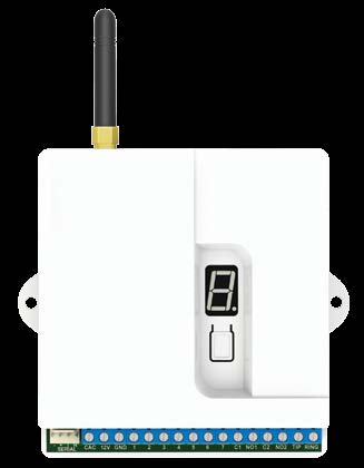
7 3. Installation 3.1 TX Cellular Plus Wiring Connections to the TXC+ are shown below: PROGRAMMING / COMMUNICATION SERIAL PORT AC MONITOR 12V DC FROM BATTERY INPUTS RELAY 1 RELAY 2 RING TIP CONTACT ID DTMF TELEPHONE CONNECTIONS TXC Plus Installation and Operations Guide (v1.1) 7
8 3.1.1 Power Supply The TXC+ must be connected to a stable 12V DC (nominal 13.2V) power supply. If a battery is available in the alarm panel, it must preferably be powered directly from the battery Check AC The Check AC (CAC) input detects the presence of the AC supply and is used to check for power failure. The CAC line should be connected to one of the transformer s SECONDARY terminals. Do NOT connect this line to the mains. The CAC line will detect AC voltages between 10 and 24V. If the CAC line is not connected, the TXC+ should not be programmed to send AC Failure or Restoral Signals. The AC Failure and AC Restore signals have a 10 minute delay in order to prevent false triggers. 8 TXC Plus Installation and Operations Guide (v1.1)
9 3.1.3 Dry Contact Inputs The dry contact inputs can be used to detect alarms generated from the outputs of the alarm panel or from other sources. If the external device generates the alarm by pulling the input to ground (negative trigger), the pull-up jumper should be inserted on the input of the TXC Contact ID Inputs The TXC+ can intercept signals sent by the alarm panel on its telephone line (Contact ID) interface. If the Contact ID interface is to be used, the alarm panel s TIP and RING lines should be connected to the TIP and RING lines on the TXC+. The alarm panel must be programmed to use its dialler, and the option for reporting must be set to Contact ID. Refer to the programming manual of the applicable alarm panel. The TXC+ can be programmed to use its own account code or the account code of the alarm panel when sending alarms received via the Contact ID interface Serial Port The TXC+ can receive alarms from the following alarm panels on its serial port: TXC Plus Installation and Operations Guide (v1.1) 9
10 Texecom premier range (panel uploads and downloads can also be done) Paradox E65, SP6000 and MG5050 Pima Relay Outputs Two dry-contact relay outputs are available on the TXC+. These outputs can be commanded to turn on and off via the GSM network or by using the option of the on-board remote control receiver. The outputs are rated to 24V AC or DC, up to a maximum of 5A. 3.2 TX Cellular Plus Installation Software Version Connect the TXC+ to the 12V supply, observing polarity. On startup, the TXC+ will display its software and hardware versions, e.g. Example: For the Software Version 1.48 and hardware version C. The software version is only displayed for version 1.40 and above. 10 TXC Plus Installation and Operations Guide (v1.1)
11 3.3 GSM Connection and Signal Strength The performance of the TXC+ depends on the quality of its connection to the GSM network. The TXC+ will send alarms more quickly and reliably if it has a strong connection to the GSM service provider. When the TXC+ has powered up, it will start connecting to the network, displaying its status as it initialises and connects (see section 3 Indicators and Controls). When the TXC+ has connected to the GSM network, it will display the SIM Card Number which it is using and the signal strength of the connection. Example: 8888 Connected on SIM Card 1 Signal Strength 6 The minimum signal strength required is 5. If an adequate signal strength is not obtained Move the TXC+ to a more suitable location Fit the TXC+ with a higher gain antenna (available from FSK) TXC Plus Installation and Operations Guide (v1.1) 11
12 3.4 Changing the Default SIM Card The TXC+ units which have been fitted with two SIM cards (Dual SIM unit) have the option of changing the default SIM card to be used. The default SIM card should be changed to the one with the highest signal strength. Press and hold-down the push-button until the TXC+ swaps SIM cards and restarts using the new SIM card (section 3 describes what is displayed). Wait until the TXC+ has re-connected to the GSM network on the new SIM card and displays the signal strength. If the TXC+ displays an error message (E1 or E4), the selected SIM card is not working and the other one should be selected. Do NOT change the SIM card on Single SIM units (TXC+ with only one SIM card fitted) as it will not be able to connect to the GSM network and send alarms. The minimum signal strength required is 5. Lower than this signal strength will make it difficult to access the TXC+ remotely. 12 TXC Plus Installation and Operations Guide (v1.1)
13 3.5 Selecting the Alarm Panel Serial Port Format The alarm panel serial port can be selected via the on-board push button (as well as the PC based programming software). The following serial port formats are available: Texecom Premier (programming required) Appendix B Paradox (MG5050, SP6000, SP65) Appendix C Pima Appendix D RhinoBus (FSK) FSK 9600 (For expansion boards) To change the serial port format: Remove the power from the TXC+ Hold down the push-button and re-apply the power Push the button to cycle through the panel serial port settings until the correct serial port is displayed. Leave the button for 15 seconds. The TXC+ will reset and remember the new serial port format TXC Plus Installation and Operations Guide (v1.1) 13
14 DISPLAY SERIAL FORMAT F Pima Hunter Pro and FSK 6 Zone Panel t Texecom Premier P Paradox 9 FSK 9600 (for expander boards) r Rhino Bus 3.6 Indicators and Controls The TXC+ has a seven segment display which indicates the current operating status TXC+ Status: 14 TXC Plus Installation and Operations Guide (v1.1)
15 CHARACTER FLASHED STATUS DESCRIPTION i r c (lower case) Initialising Restarting Connecting C (upper case) Connected C S d S F 2 Connecting to server Disconnecting from server Send SMS The TXC+ is starting the GSM modem The TXC+ is re-starting the GSM modem The TXC+ is connecting to the GSM network The TXC+ is connected to the GSM network and is ready to send alarms Sending GPRS alarms All alarms sent, disconnecting from the server Sending an SMS to the control room or a cellphone TXC Plus Installation and Operations Guide (v1.1) 15
16 TXC+ Errors - If the TXC+ detects an error, it will flash the error code on the seven segement display. CHARACTER FLASHED STATUS DESCRIPTION 88 The TXC+ has been stunned E0 Stunned and will not send messages The TXC+ has 88 not detected a SIM card not E1 SIM card which found it has been programmed to use E2 E3 E4 Reserved SMS Sending has failed Connection to Server has failed The TXC+ cannot send the message via SMS The TXC+ cannot connect to the server to send the alarms 16 TXC Plus Installation and Operations Guide (v1.1)
17 Diagnostics of Error Codes: ERROR STATE Stunned No SIM card CAUSE The TXC+ has been sent a stun message via SMS and will no longer send any alarms. Or The TXC+ has sent too many SMS messages in a period of time and is stopping a run-away SMS condition (250 SMS messages in an hour) There is no SIM card inserted in a SIM holder and the TXC+ has been programmed to use that SIM card Or The SIM card is damaged CORRECTIVE ACTION Send the TXC+ the Un-stun SMS Make sure that a SIM card is correctly inserted in the holder If there is only one SIM card installed, make sure that the TXC+ is not programmed to use the open SIM holder (no SMS or GPRS capabilities on the SIM card) TXC Plus Installation and Operations Guide (v1.1) 17
18 SMS fail The TXC+ cannot send the SMS Or The network has returned an error in response to the TXC+ sending the SMS Make sure that the SIM card is capable of sending SMS messages If it is a pay as you go SIM card, make sure that it has available funds loaded onto the SIM card Make sure that the SIM card is capable of connecting to the GPRS network Server Connection Fail The TXC+ cannot connect to the FSK server to route the GPRS message to the control room Make sure that the programming of the Server GPRS settings are correct If it is a pay as you go SIM card, make sure that it has available funds loaded onto the SIM card The GSM network may be experiencing technical problems. Contact the GSM provider 18 TXC Plus Installation and Operations Guide (v1.1)
19 4. Programming 4.1 On-Board Push Button The on-board push-button can be used to: Change the operation of the serial port (select the alarm panel) Change the default SIM card to be used (dual SIM units only) Refer to section PC based Programmer The FSK TX Cellular+ Setup utility is a Windows based programmer which is used as the primary means of programming the TXC+. The TXC+ programmer requires a PC running Windows XP or Windows 7 with an available COM Port (a USB to Serial Adapter can also be used). The FSK USB programming cable is required to program the TXC+ (see Appendix E). 4.3 SMS Programming Many of the settings on the TXC+ can be changed by sending a SMS to the unit. The SMS commands are shown in Appendix A. TXC Plus Installation and Operations Guide (v1.1) 19
20 Appendix A SMS COMMANDS AND PROGRAMMING The TXC+ has a number of SMS commands and programming commands which can be used to: Activate the outputs Request the unit status Change programming information and request current programming information If the TXC+ is to reply to any of these commands and programming updates, the SMS function has to be enabled on the SIM card. FSK supplied SIM cards cannot send SMS s, but they can receive SMS s for control commands. SMS Commands Activate the outputs on the TXC+. The default Keywords are shown. The Keywords can be changed via the programming software. 20 TXC Plus Installation and Operations Guide (v1.1)
21 KEYWORD DESCRIPTION NOTES 1On Turn output 1 on (Relay 1) 1Off Turn output 1 off (Relay 1) 2On Turn output 2 on (Relay 2) 2Off Turn output 2 off (Relay 2) 3On. Turn outputs 3 10 on the 10On expansion module on 3Off. 10Off Turn outputs 3 10 on the expansion module off Format is output number (3-10) and output state (on/off) Change the default SIM card to be used (for TXC+ units fitted with two SIM cards). Use this command with care as it will stop the TXC+ from functioning if a SIM card is selected which is not installed or activated. KEYWORD SELECT SIM 1 SELECT SIM 2 DESCRIPTION Select the first SIM card as the default Select the second SIM card as the default SMS Status Requests KEYWORD DESCRIPTION NOTES Status? Get full unit status Case sensitive. No spaces Balance? Get account balance Case sensitive. No spaces Note: the balance request works with pre-paid SIM cards only. TXC Plus Installation and Operations Guide (v1.1) 21
22 SMS Programming SMS programming allows some of the parameters in the unit to be changed without having to physically go to the unit with a programming computer. NOTE: BE VERY CAREFUL WHEN PROGRAMMING THE TXC+ USING SMS s AS YOU CAN STOP THE UNIT FROM FUNCTIONING CORRECTLY. Unit Description and Phone Numbers Change the description of the TXC+ (which it uses to refer to itself in SMS s) and the phone numbers which it reports to. To change the value, send the KEYWORD followed a space, followed by the new value (shown in Italics). E.g. to change phone number 1, send 1 Phonenumber (where Phonenumber is the cell phone number) To retrieve the value, send the KEYWORD followed by? (no space), e.g. 1? (to request the phone number) Note: When requesting the phone number, the TXC+ will respond with all the stored phone numbers. 22 TXC Plus Installation and Operations Guide (v1.1)
23 KEYWORD DESCRIPTION TO CHANGE 0 Unit description 0 Name 1 Phone number 1 1 Phonenumber 2 Phone number 2 2 Phonenumber 3 Phone number 3 3 Phonenumber 4 Phone number 4 4 Phonenumber 5 Phone number 5 5 Phonenumber 6 Phone number 6 6 Phonenumber 7 Phone number 7 7 Phonenumber 8 Phone number 8 8 Phonenumber 9 Phone number 9 9 Phonenumber 10 Phone number Phonenumber 11 GPRS fallback num 11 Phonenumber 12 Sim 1 SMS Centre number (MTN) 13 Sim 2 SMS Centre number (Vodacom) Timers KEYWORD DESCRIPTION VALUE 58 AC fail/restore 1 to 60. (e.g. 60 = 60 mins = 1hr) delay (minutes) 59 Battery fail restore delay 1 to 60. (e.g. 60 = 60 mins = 1hr) TXC Plus Installation and Operations Guide (v1.1) 23
24 1179 SMS self test interval 1180 GPRS test interval 10 to (10 min to 100 hrs) 10 to (10 min to 100 hrs) SMS Text - Inputs KEYWORD DESCRIPTION 256 AC OK (AC Restored) SMS Text 257 Battery OK SMS Text 322 AC Failed SMS Text 323 Battery low SMS Text 258 Input 1 High SMS Text 259 Input 2 High SMS Text 260 Input 3 High SMS Text 261 Input 4 High SMS Text 262 Input 5 High SMS Text 263 Input 6 High SMS Text 264 Input 7 High SMS Text 324 Input 1 Low SMS Text 325 Input 2 Low SMS Text 326 Input 3 Low SMS Text 327 Input 4 Low SMS Text 328 Input 5 Low SMS Text 329 Input 6 Low SMS Text 330 Input 7 Low SMS Text 24 TXC Plus Installation and Operations Guide (v1.1)
25 SMS Text Missed Call KEYWORD DESCRIPTION 398 Missed Call SMS text TXC Plus Installation and Operations Guide (v1.1) 25
26 Appendix B TEXECOM SERIAL INTERFACE The TXC+ can receive alarms from the Texecom Premier range of alarm panels. Using a modem connected to a computer, the TXC+ can also be used to remotely upload and download the Texecom premier alarm panels. TXC+ to Texecom Premier Serial Interface Cable TEXECOM PANEL MOLEX WAY GREEN BLUE BLACK WIRE 1m FSK TX CELLULAR MOLEX WAY (OPEN) 4 (12V) 5 DATA PANEL - RADIO DATA PANEL - PANEL GND GREEN BLUE BLACK TXC Plus Installation and Operations Guide (v1.1)
27 Programming of the Texecom Premier two COM Port Alarm Panel Program the TXC+ to use the Texecom Serial Alarm Interface (DTMF Serial Interface Tab) The TXC+ is connected to COM1 on the Alarm Panel The following programming is required on the Texecom panel: MENU 71 MENU 70 MENU TEL NO 22 (YES) 1 - ACC CODE 3456 (YES) 2 - PROTOCOL TYPE = 4 (CONTACT ID) 3 - DIALLER ATTEMPTS = PARTITION (SELECT PARTITIONS 1 AND 2) 5 - SELECT REPORTING OPTIONS 1,2,5,8 ON (ENABLE COMMUNICATOR) OPTION 5 COM 1 DEVICE TYPE ENTER 3 ComIP PROTOCOL OPTION 6 COM IP ADDRESS/PORT ENTER (spaces for readability) OPTION 8 COM IP SUBNET MASK ENTER 8 Uploading and Downloading the Texecom Premier Alarm Panel The Texecom premier alarm panel can be uploaded and downloaded using the Texecom WinTex software (available at TXC Plus Installation and Operations Guide (v1.1) 27
28 Please contact the local Texecom agent for more details. Software is available from FSK Electronics which can be used to connect to the Alarm Panel (via the TXC+). Please refer the FSK APN USER GUIDE. 28 TXC Plus Installation and Operations Guide (v1.1)
29 Appendix C PARADOX SERIAL INTERFACE The TXC+ can send alarms received from the serial port of the Paradox E65, MG5050 and SP6000 alarm panels. TXC+ TO PARADOX E65/SP6000/MG5050 SERIAL CABLE Marked T T MOLEX GREEN NOT USED BLUE NOT USED BLACK DATA PANEL - TXC+ GND NOT USED NOT USED 1 P MOLEX 2510 Marked P Events Sent By the Paradox Alarm Panel The table below shows the Contact ID codes which will be sent in response to the messages received from the Paradox E65/MG5050 and SP6000 alarm panel serial ports. TXC Plus Installation and Operations Guide (v1.1) 29
30 EVENT GROUP NO 06 = Non Reportable Event PARADOX SUB-GROUP NO CONTACT ID CODE CONTACT ID EVENT (1) RESTORE (3) ZONE/ USER 00 = Telephone Line Trouble = Arming with User = User Number USER 30 = Special Arming 31 = Disarming with User 32 = Disarming after Alarm with user 34 = Special Disarming 36 = Zone In Alarm 37 = Fire Alarm 01 to 32 = Zone Number 38 = Zone Alarm Restore 40 = Special Alarm 42 = Zone Tampered 03 = Partial Arming = Arm Keyswitch = Arm Keyswitch = User Number USER = User Number USER N/A USER 05 = Disarming with Keyswitch USER 01 to 32 = Zone Number ZONE ZONE 01 to 32 = Zone Number ZONE 00 = Panic nonmedical emergency = Panic medical = Panic Fire = Duress Alarm = Zone Number ZONE 30 TXC Plus Installation and Operations Guide (v1.1)
31 EVENT GROUP NO 44 = New Trouble 45= Trouble Restore 46 = Bus/ wireless module new trouble 48 = Special (Partition 1 only) PARADOX SUB-GROUP NO 01 = AC Failure CONTACT ID CODE CONTACT ID EVENT (1) RESTORE (3) ZONE/ USER = Batt Fail = Bell Current Overload = Bell disconnected = Fail To Communicate Tel = Fail to Communicate Tel = fail to Communicate Pager = fail to communicate voice = AC Failure Restore = Batt Fail restore = Bell Current Overload Rest = tamper Trouble = Reporting Test = Installer Entered Prog Mode = Installer Exited Prog Mode = Maintenance Exited Prog Mode TXC Plus Installation and Operations Guide (v1.1) 31
32 49 = Low Battery on Zone 50 = Low Battery on Zone Restore 51 = Zone supervision trouble 52 = Zone Supervision restore 53 = Wireless Module Sup Trbl 54 = Wireless Module Sup Rest 55 = Wireless Module Tamper Trbl 56 = Wireless Module Tamper Rest = Zone Number = Zone Number = Zone Number ZONE ZONE ZONE 01 to 32 = Zone Number ZONE ZONE ZONE ZONE ZONE 32 TXC Plus Installation and Operations Guide (v1.1)
33 Appendix D PIMA SERIAL INTERFACE PIMA ALARM PANEL MOLEX WAY WIRE 1m MOLEX WAY FSK TXC DATA PANEL - RECEIVER DATA PANEL - PANEL GND GREEN BLUE BLACK The Pima serial interface will send the standard FSK Contact ID alarm codes. TXC Plus Installation and Operations Guide (v1.1) 33
. 34 TXC Plus Installation and Operations Guide (v1.")
34 Appendix E PROGRAMMING CABLE AND SOFTWARE The TXC+ is programmed using the FSK USB Programming Cable and FSK DVD which contains the programming software (FSK Item Code 40027). 34 TXC Plus Installation and Operations Guide (v1.1)

35 Installing the Drivers for the FSK USB to UART Programmer Install the drivers before plugging the USB Programmer into the computer s USB port In the FSK DVD, navigate to the following directory: \FUSA FSK USB Serial Adapter Drivers Click on Intall_Fusa_Drivers Follow the instructions on the driver software. TXC Plus Installation and Operations Guide (v1.1) 35

36 Installing the TXC+ Programming Software On the FSK DVD, navigate to the following directory: \TX Cellular Plus GSM Transceiver\TXC+ V1.23 Prog Software Setup (All PC s) Double click on the setup.exe application Follow the instructions on the setup application NOTE: THE TXC+ PROGRAMMING SOFTWARE HAS TO BE SET UP TO USE THE COM PORT WHICH HAS BEEN ASSIGNED TO THE USB PROGRAMMER In the TXC+ programming software, click on SETTINGS 36 TXC Plus Installation and Operations Guide (v1.1)
 37")
37 Select the correct COM Port Number TXC Plus Installation and Operations Guide (v1.1) 37
38 TROUBLESHOOTING 14 Richard Road, Industria North, Johannesburg, South Africa T: +27 (0) E: CALL CENTER: TXC Plus Installation and Operations Guide (v1.1)
39
40 INNOVATORS IN WIRELESS TECHNOLOGY
IRIS Touch 600 Range Dialler Installation Manual. Version 1.3
 IRIS Touch 600 Range Dialler Installation Manual Version 1.3 The information contained is supplied without liability for any errors or omissions. No part may be reproduced or used except as authorised
PRT3 Printer Module: ASCII Protocol Programming Instructions
 PRT3 Printer Module: ASCII Protocol Programming Instructions We hope this product performs to your complete satisfaction. Should you have any questions or comments, please visit www.paradox.com and send
Firmware version: 1.10 Issue: 7 AUTODIALER GD30.2. Instruction Manual
 Firmware version: 1.10 Issue: 7 AUTODIALER GD30.2 Instruction Manual Firmware version: 2.0.1 Issue: 0.6 Version of the GPRS transmitters configurator: 1.3.6.3 Date of issue: 07.03.2012 TABLE OF CONTENTS
Magellan All-in-one Wireless Security System
 Magellan All-in-one Wireless Security System MG6250 Console Version 1.0 Menu Programming Guide Introduction The MG6250 All-in-one Wireless Console is a two-partition, 64-zone wireless console, offering
APR-PRT3 Printer Module: C-Bus Programming Instructions
 APR-PRT3 Printer Module: C-Bus Programming Instructions We hope this product performs to your complete satisfaction. Should you have any questions or comments, please visit www.paradox.com and send us
Elvey is a leading distributor of electronic security equipment in Africa. Our vision is to assist in the protection of people and property by
 Elvey is a leading distributor of electronic security equipment in Africa. Our vision is to assist in the protection of people and property by providing quality, innovative products and solutions to the
Installation Manual Premier Elite ComIP
 Installation Manual Premier Elite ComIP INS273-5 Overview Introduction The ComIP module allows the Premier & Premier Elite control panels to be connected to either a Local Area Network (LAN) or Wide Area
Security module CG2 User manual
 Security module CG2 User manual TRIKDIS, JSC Draugystes str. 17, LT-51229 Kaunas LITHUANIA E-mail [email protected] Web http://www.trikdis.lt This manual is furnished to help You understand Your security
INS580. Apps for Android. Android is a trademark of Google Inc.
 INS580 Apps for Android Android is a trademark of Google Inc. The Android robot is reproduced or modified from work created and shared by Google and used according to terms described in the Creative Commons
Rev 06 1211. GSM base station. Installation instructions
 Rev 06 1211 GSM base station Installation instructions Output string format Baud rate 115200 bps Parity none Data bits 8 Stop bits 1 Flow control none The output string is a modified version of the Sureguard
GSM Autodialer Professional GJD700 Speech & Text Autodialer
 Text Edit message GSM Autodialer Professional GJD700 Speech & Text Autodialer Introduction The GSM Autodialer Professional works in conjunction with standard alarm systems and makes use of your preferred
User Guide Wintex Software
 User Guide Wintex Software INS549 Contents Contents... 2 Tool Bar Commands... 40 Introduction... 3 Panel Language Editor Premier 412/816/ & 832. 41 Installation... 3 Introduction... 41 Starting Wintex...
Ademco Vista-20P/First Alert FA-168C Basic Commands
 Zones 64 total Ademco Vista-20P/First Alert FA-168C Basic Commands Wireless Yes, Zones 09 to 48 + 16 Keyfob Zones (Zones 49 to 64) Batteries Downloadable Partitions 2 12 volt Rechargable inside main Panel,
User s Information Guide R1A
 HSC505-R Home Security Controller - User Manual Release R1a Pi HSC505 and Pi HSC505R Home Security Controller User s Information Guide R1A Page 1 QD Dynamics (Pty) Ltd reserves the right to make changes
CA60 Plus Software Version 3.1 User Manual May 2000
 TeleT eletek ek CA60 Plus Software Version 3.1 User Manual May 2000 CONTENTS 1. CA60Plus Keypad... 3 1.1. LED display... 3 1.2. Keys... 4 1.3. Combinations of Keys... 4 1.4. Audible Indication... 4 2.
ON-GUARD. Guard Management System. Table of contents : Introduction Page 2. Programming Guide Page 5. Frequently asked questions Page 25 - 1 -
 ON-GUARD Guard Management System Table of contents : Introduction Page 2 Programming Guide Page 5 Frequently asked questions Page 25-1 - Introduction On Guard tm is designed to exceed all the requirements
ABUS WIRELESS ALARM SYSTEM
 ABUS WIRELESS ALARM SYSTEM These installation instructions are published by Security-Center GmbH & Co. KG, Linker Kreuthweg 5, D-86444 Affing/Mühlhausen. All rights including translation reserved. Reproductions
Arduino Wifi shield And reciever. 5V adapter. Connecting wifi module on shield: Make sure the wifi unit is connected the following way on the shield:
 the following parts are needed to test the unit: Arduino UNO R3 Arduino Wifi shield And reciever 5V adapter Connecting wifi module on shield: Make sure the wifi unit is connected the following way on the
SMS Alarm Messenger. Setup Software Guide. SMSPro_Setup. Revision 090210 [Version 2.2]
![SMS Alarm Messenger. Setup Software Guide. SMSPro_Setup. Revision 090210 [Version 2.2]](/thumbs/29/13662687.jpg "SMS Alarm Messenger. Setup Software Guide. SMSPro_Setup. Revision 090210 [Version 2.2]") SMS Alarm Messenger SMSPro_Setup Revision 090210 [Version 2.2] ~ 1 ~ Contents 1. How to setup SMS Alarm Messenger?... 3 2. Install the SMSPro_Setup software... 5 3. Connection Type... 6 4. Connection Port
SMS Alarm Messenger SMSPro_Setup Revision 090210 [Version 2.2] ~ 1 ~ Contents 1. How to setup SMS Alarm Messenger?... 3 2. Install the SMSPro_Setup software... 5 3. Connection Type... 6 4. Connection Port
New GSM Alarm System. User s Manual. Profile For a better understanding of this product, please read this user manual thoroughly before using it.
 New GSM Alarm System User s Manual Profile For a better understanding of this product, please read this user manual thoroughly before using it. Chapter 1. Features Chapter 2. Alarm Host Introduction Chapter
Control/Communicator Installation Manual
 DAS NETWORX NX-8 Control/Communicator Installation Manual Page General Description... 2 Ordering Information... 2 Option Definitions... 2 Programming the LED Code Pads... 4 Programming the NX-8... 8 Types
PM1122 INT DIGITAL INTERFACE REMOTE
 PM1122 INT DIGITAL INTERFACE REMOTE PM1122 INT front panel description: 1. Clear wireless remotes knob: push this button for more than 2 seconds to clear the list of all assigned wireless remote settings
Apps for Android. Apps for iphone & ipad INS584-3
 Apps for iphone & ipad INS584-3 Apps for Android Android is a trademark of Google Inc. iphone is a trademark of Apple Inc., registered in the U.S. and other countries. ipad is a trademark of Apple Inc.,
SNMP Web Management. User s Manual For SNMP Web Card/Box
 SNMP Web Management User s Manual For SNMP Web Card/Box Management Software for Off-Grid Inverter Version: 1.2 Table of Contents 1. Overview... 1 1.1 Introduction... 1 1.2 Features... 1 1.3 Overlook...
Andover Continuum Remote Communication Configuration Guide
 Andover Continuum Remote Communication Configuration Guide 2010, Schneider Electric All Rights Reserved No part of this publication may be reproduced, read or stored in a retrieval system, or transmitted,
200 Range Dialer Installation Manual. Version 1.0
 200 Range Dialer Installation Manual Version 1.0 The information contained is supplied without liability for any errors or omissions. No part may be reproduced or used except as authorised by contract
NStar Build 648. Release Notes. Page 1 of 17
 NStar Build 648 Release Notes Page 1 of 17 This page is left blank intentionally Page 2 of 17 NStar Build 648 Release Notes Release notes NStar Build 648 Overview These release
Quick Start Guide Vodafone Mobile Broadband USB Stick. Designed for Vodafone
 Quick Start Guide Vodafone Mobile Broadband USB Stick Designed for Vodafone Welcome to the world of mobile communications 1 Welcome 2 Set up your USB Stick 3 Start the software 4 Software overview (Microsoft
Business/Home GSM Alarm System. Installation and User Manual
 Business/Home GSM Alarm System Installation and User Manual Brief Introduction: GSM 900/1800/1900 bands, can be used in most parts of the world Full duplex communication with the host Monitor the scene
GSM Communicator Module PCS100 V1.1
 GSM Communicator Module PCS100 V1.1 Installation and User Manual Warranty Paradox Security Systems Ltd. ( Seller ) warrants its products to be free from defects in materials and workmanship under normal
GSM Alarm System User Manual
 GSM Alarm System User Manual For a better understanding of this product, please read this user manual thoroughly before using it. Quick Guider After getting this alarm system, you need to do the following
Quick Installation Guide LCD GSM ALARM SYSTEM LH http://www.usmartbuy.com
 A. Manipulation Specification Quick Installation Guide 1. Arming Arming means all-around guarded when there is no person at home. All detectors are working. Once something triggers any of the detectors,
Crow Limited Warranty. Print Version 017
 Crow Limited Warranty (Crow) warrants this product to be free from defects in materials and workmanship under normal use and service for a period of one year from the last day of the week and year whose
32-Zone Wireless Transceiver Security Systems MG5000 V3.2 MG5050 V3.2. 5- to 32-Zone Expandable Security Systems SP5500 V3.2 SP6000 V3.2 SP7000 V3.
 32-Zone Wireless Transceiver Security Systems MG5000 V3.2 MG5050 V3.2 5- to 32-Zone Expandable Security Systems SP5500 V3.2 SP6000 V3.2 SP7000 V3.2 Always Armed, Never Disarmed Programming Guide PARADOX.COM
ICP-CC488 ICP-CC488 EN. Control Panel. Quick Reference Guide
 ICP-CC488 EN Quick Reference Guide ICP-CC488 Control Panel ICP-CC488 Quick Reference Guide Notices EN 2 Copyright Notice Unless otherwise indicated, this publication is the copyright of Bosch Security
Intelligent GSM Auto-dial Alarm System User s Manual
 Intelligent GSM Auto-dial Alarm System User s Manual Profile For a better understanding of this product, please read this user manual thoroughly before using it. [Function Instruction] [Control Panel Introduction]
TCP/IP MODULE CA-ETHR-A INSTALLATION MANUAL
 TCP/IP MODULE CA-ETHR-A INSTALLATION MANUAL w w w. c d v g r o u p. c o m CA-ETHR-A: TCP/IP Module Installation Manual Page Table of Contents Introduction...5 Hardware Components... 6 Technical Specifications...
CCTR-805-V2 3G Car GPS Tracker-201604
 CCTR-805-V2 3G Car GPS Tracker-201604 Welcome to use this real time car GPS tracker CCTR-805G.This product is with GPS module and 2G GSM / 3G WCDMA module (with LBS locate without GPS), that has many new
TECHNICAL BULLETIN. Configuring Wireless Settings in an i-stat 1 Wireless Analyzer
 i-stat TECHNICAL BULLETIN Configuring Wireless Settings in an i-stat 1 Wireless Analyzer Before configuring wireless settings, please enable the wireless functionality by referring to the Technical Bulletin
A L ERT. Quick Start With
 A L ERT Quick Start With I NSTAL L ATION To launch the installation of Micromedia Solution, insert the installation CD-ROM in the CD/DVD drive. If the installation program does not start automatically
WA Manager Alarming System Management Software Windows 98, NT, XP, 2000 User Guide
 WA Manager Alarming System Management Software Windows 98, NT, XP, 2000 User Guide Version 2.1, 4/2010 Disclaimer While every effort has been made to ensure that the information in this guide is accurate
Information Manual. Ricochet Monitor INS550-2
 Information Manual Ricochet Monitor INS550-2 Contents Ricochet Monitor Help & Information Contents... 2 Introduction... 3 Installation... 4 Language Selection... 4 Connect/Disconnect... 4 USB Connection...
Configuration Programme
 Configuration Programme Handbook Version 4.0 Index Introduction...3 Software Installation...4 The Configuration Programme...6 Options Menu...6 The Configurator... 8 General Settings...8 Telephone book...10
COMPLETE SETUP AND PROGRAMMING MANUAL FOR XT600i GPRS PANEL
 COMPLETE SETUP AND PROGRAMMING MANUAL FOR XT600i GPRS PANEL *A Videofied CMA601 Alphanumeric Keypad or Frontel TMTi is required for programming and maintenance CMA601 4455 White Bear Parkway 877-206-5800
Sierra Wireless AirCard Watcher Help for Mac OS X
 Sierra Wireless AirCard Watcher Help for Mac OS X Sierra Wireless AirCard Watcher allows you to manage and monitor the connection between your modem and the network. With Watcher, you can: Determine signal
STATUS POWER MONITOR ALARM SOS DISARM
 STATUS POWER MONITOR ALARM SOS DISARM I. Features II. Preparation before use III. Host 1.LED status explanation 2. Host panel IV. System Settings 1. Coding of wireless sensors 2. Exit coding 3. Settings
F2103 GPRS DTU USER MANUAL
 F2103 GPRS DTU USER MANUAL Add:J1-J2,3rd Floor,No.44,GuanRi Road,SoftWare Park,XiaMen,China 1 Zip Code:361008 Contents Chapter 1 Brief Introduction of Product... 3 1.1 General... 3 1.2 Product Features...
Application Note Connect to a Rockwell PLC over Netbiter Remote Access
 Application Note Connect to a Rockwell PLC over Netbiter Remote Access Doc: HMSI 27-239 Rev: 1.0 Connecting Devices TM HALMSTAD CHICAGO KARLSRUHE TOKYO BEIJING MILANO MULHOUSE COVENTRY PUNE COPENHAGEN
PCS250 - GPRS/GSM Communicator Module V1.0 Reference and Installation Manual
 PCS250 - GPRS/GSM Communicator Module V1.0 Reference and Installation Manual PARADOX.COM Printed in Canada - 07/2012 PCS250-EI00 Table of Contents Introduction... 4 Features... 4 Overview... 6 System
USB GSM 3G modem RMS-U-GSM-3G. Manual (PDF) Version 1.0, 2014.8.1
 Version 1.0, 2014.8.1") USB GSM 3G modem RMS-U-GSM-3G Manual (PDF) Version 1.0, 2014.8.1 2014 CONTEG, spol. s r.o. All rights reserved. No part of this publication may be used, reproduced, photocopied, transmitted or stored in
USB GSM 3G modem RMS-U-GSM-3G Manual (PDF) Version 1.0, 2014.8.1 2014 CONTEG, spol. s r.o. All rights reserved. No part of this publication may be used, reproduced, photocopied, transmitted or stored in
AMPS Information. The keypad pictures listed here may vary from your panel type.
 AMPS Information General Notes: The communication of your ADT Alarm System may be impacted as a result of the recent FCC ruling allowing phone / cellular service providers to switch to a digital only format.
Solution-16 Operators Manual ISSUE 1.60
 Solution-16 Operators Manual ISSUE 1.60 !"#$%&"'()*+ Operators Manual Copyright 2002 by, SYDNEY, AUSTRALIA Document Part Number MA880O DOCUMENT ISSUE 1.60 Printed 22 March 2002 This documentation is provided
Ethernet Radio Configuration Guide
 Ethernet Radio Configuration Guide for Gateway, Endpoint, and Repeater Radio Units April 20, 2015 Customer Service 1-866-294-5847 Baseline Inc. www.baselinesystems.com Phone 208-323-1634 FAX 208-323-1834
DIRECT INTERNET DATA. User s Guide
 DIRECT INTERNET DATA User s Guide Iridium Satellite LLC Rev. 2; June 15, 2001 DIRECT INTERNET DATA ------------------------------------------------------------------------------------- TABLE OF CONTENTS
Business/Home. GSM Alarm system
 Business/Home GSM Alarm system Installation and Users guide Profile For a better understanding of this product, please read this user manual thoroughly before using it. I. General information: GSM 900/1800/1900
GSM HOME SECURITY SYSTEM
 Cell /Mobile phone home security system GSM HOME SECURITY SYSTEM Model : GSM-120 TABLE OF CONTENTS 1. FEATURES... 1 2. APPLICATION... 2 3. SPECIFICATIONS... 3 4. FRONT PANEL & LAYOUT DESCRIPTION...6 5.
CAPTAIN 6. USER GUIDE System ver. 6.0. 6 Zones Intruder Alarm System. PIMA Electronic Systems Ltd. www.pima-alarms.com
 CAPTAIN 6 6 Zones Intruder Alarm System USER GUIDE System ver. 6.0 PIMA Electronic Systems Ltd. www.pima-alarms.com P/N 4410049, G2 XX en, Jan. 2010 2 CAPTAIN 6 User Guide SAFETY INSTRUCTIONS Your CAPTAIN-i
CMP-102U. Quick Installation Guide
 CMP-102U Quick Installation Guide V1.0 http://www.cnet.com.tw 1 CMP-102U Supports One High-speed USB2.0 Port MFP Server Supports 10/100Mbps Fast Ethernet Network Quick Installation Guide 1 Package Contents:
Installing the IF-NMEASC & SC30 Windows XP Drivers & Software
 Installing the IF-NMEASC & SC30 Windows XP Drivers & Software The following document will outline the installation and use of the IF-NMEASC and SC-30 USB drivers and SC-30Tool software in three parts:
Bluetooth + USB 16 Servo Controller [RKI-1005 & RKI-1205]
![Bluetooth + USB 16 Servo Controller [RKI-1005 & RKI-1205]](/thumbs/40/21161302.jpg "Bluetooth + USB 16 Servo Controller [RKI-1005 & RKI-1205]") Bluetooth + USB 16 Servo Controller [RKI-1005 & RKI-1205] Users Manual Robokits India [email protected] http://www.robokitsworld.com Page 1 Bluetooth + USB 16 Servo Controller is used to control up to
Bluetooth + USB 16 Servo Controller [RKI-1005 & RKI-1205] Users Manual Robokits India [email protected] http://www.robokitsworld.com Page 1 Bluetooth + USB 16 Servo Controller is used to control up to
TX GSM SMS Auto-dial Alarm System. Installation and User Manual
 TX GSM SMS Auto-dial Alarm System Installation and User Manual Product Features: 1. 16 wireless zones, 3 wired zones alarm system, suitable for small to medium size offices and homes. 2. The system uses
for Windows Media Center User's Guide
 for Windows Media Center User's Guide Table of Contents Introduction System Requirements Installation Running HAI Home Control Using HAI Home Control Product Support Introduction Thank you for purchasing
Business/Home GSM. Alarm System(III) Installation and Users guide
 Installation and Users guide") Business/Home GSM Alarm System(III) Installation and Users guide I. General information: GSM 900/1800/1900 bands, can be used all over the world. Full duplex communication with the base. Monitor environment
Business/Home GSM Alarm System(III) Installation and Users guide I. General information: GSM 900/1800/1900 bands, can be used all over the world. Full duplex communication with the base. Monitor environment
To perform Ethernet setup and communication verification, first perform RS232 setup and communication verification:
 PURPOSE Verify that communication is established for the following products programming option (488.2 compliant, SCPI only): DCS - M9C & DCS M130, DLM M9E & DLM-M9G & DLM M130, DHP - M9D, P series, SG,
Keep it Simple Timing
 Keep it Simple Timing Support... 1 Introduction... 2 Turn On and Go... 3 Start Clock for Orienteering... 3 Pre Start Clock for Orienteering... 3 Real Time / Finish Clock... 3 Timer Clock... 4 Configuring
Connecting your Omega/BetaPAT PLUS to a PC via a USB
 Connecting your Omega/BetaPAT PLUS to a PC via a USB Install software Windows XP and below Insert the disc into your computers disc drive and run through the setup wizard. Windows Vista & 7 1. Insert the
Table Of Contents. System Monitoring... 14 System Monitoring Display...14 Monitoring Zones...15 About Areas (partitions)...15 Area Status Display...
...15 Area Status Display...") Quick Start Table Of Contents Getting Started... 2 NEware Editions...2 Installing NEware...3 Installing Languages...3 Connecting to NEware...3 Changing Your IP100 Password...4 User Codes... 5 Master Feature...5
Quick Start Table Of Contents Getting Started... 2 NEware Editions...2 Installing NEware...3 Installing Languages...3 Connecting to NEware...3 Changing Your IP100 Password...4 User Codes... 5 Master Feature...5
Rapid Assessment Key User Manual
 Rapid Assessment Key User Manual Table of Contents Getting Started with the Rapid Assessment Key... 1 Welcome to the Print Audit Rapid Assessment Key...1 System Requirements...1 Network Requirements...1
CONTENTS QUICK SETUP & INSTALLATION USER MANUAL. SUPA8 Quick Setup & User Manual
 SUPA8 Quick Setup & User Manual QUICK SETUP & INSTALLATION CONTENTS FACTORY DEFAULTS... 1 INSTALLATION OF THE SECURITY SYSTEM... 2 COMMISSIONING THE DIALLER PANEL... 5 ZONE INPUT CONNECTIONS... 7 PANEL
TELL AMR-08. Monitoring Receiver. Programming Manual
 TELL AMR-08 Monitoring Receiver Programming Manual 28 / 01 / 2014 CONTENT 1. INTRODUCTION...3 2. SYSTEM STRUCTURE...3 2.1 CPM card...3 2.2 LC telephone line card (optional)...4 2.3 PWR power supply card...4
IRIS Touch 400 Range Dialler Installation Manual. Version 1.4
 IRIS Touch 400 Range Dialler Installation Manual Version 1.4 The information contained is supplied without liability for any errors or omissions. No part may be reproduced or used except as authorised
WIRELESS INTERNET TROUBLESHOOTING GUIDE. 320.834.5151 888.236.3574 www.gctel.com. Help Desk 320.834.5155
 WIRELESS INTERNET TROUBLESHOOTING GUIDE 320.834.5151 888.236.3574 www.gctel.com Help Desk 320.834.5155 Table of Contents Check Physical Connection Connection Diagram - Page 1 Power Inserter - Page 2 Identify
SECTION 13850 DETECTION AND ALARM
 SECTION 13850 DETECTION AND ALARM PART 1 GENERAL 1.01 SUMMARY A. Section Includes 1. Control Panel 2 Associated Equipment B. Products Installed But Not Supplied Under This Section 1. Section 16140 - Wiring
D8X / D16X IPHONE INTERFACE
 Ness icomms App D8X / D16X IPHONE INTERFACE SETUP GUIDE Revision 1.0.0 Table of Contents Copyright Notice... 3 1. Important Information... 4 2. Wiring Diagram... 5 2.1 RS232 Wiring Setup... 5 2.2 IP232
Voice Over Internet Protocol (VoIP) Configuration
 Configuration") (VoIP) Configuration ENGINEERING REPORT No: 02-003 Introduction This report describes interfacing the IPCS VoIP Gateway Model EGW-902 to an ESTeem Model 192E Wireless Ethernet radio modem in a demonstration
(VoIP) Configuration ENGINEERING REPORT No: 02-003 Introduction This report describes interfacing the IPCS VoIP Gateway Model EGW-902 to an ESTeem Model 192E Wireless Ethernet radio modem in a demonstration
Quick Start Guide Vodafone Mobile Broadband USB Modem Stick. Designed for Vodafone
 Quick Start Guide Vodafone Mobile Broadband USB Modem Stick Designed for Vodafone Welcome to the world of mobile communications 1 Welcome 2 Set up your USB Modem Stick 3 Start the software 4 Software overview
Car Alarm Tracker Manual-20150814
 CCTR-922 Car Alarm Tracker Manual-20150814 Welcome to use this GSM car alarm with tracker function CCTR-922. this product use 2G GSM network (LBS locate) to locate the car, it has many new and unique functions,
Temperature & Humidity SMS Alert Controller
 Temperature & Humidity Alert Controller METERS 3 simple steps starting the unit: Insert the SIM card Plug in the sensors connectors Connect the AC power cord. Specifications: AC 90~260V Auto Select Internal
1. Make sure that no client accounts are open. 2. Click on Setup, then click Modem. The Modem Setup window will appear.
 SECURITY SYSTEM MANAGEMENT SOFTWARE FOR WINDOWS WINLOAD MODEM SETUP The modem setup is a very important step in the connection process. If the modem setup is not properly completed communication between
About This Guide SolarEdge Configuration Tool Software Guide. About This Guide
 About This Guide 3 About This Guide This user guide is intended for Photovoltaic (PV) system owners, installers, technicians, maintainers, administrators and integrators who are authorized to configure
ICP-CC488. Installation Guide ICP-CC488 Control Panel
 ICP-CC488 EN Installation Guide ICP-CC488 Control Panel ICP-CC488 Installation Guide Notices EN 2 Copyright Notice Unless otherwise indicated, this publication is the copyright of Bosch Security Systems,
Movie Cube. User s Guide to Wireless Function
 Movie Cube User s Guide to Wireless Function Table of Contents 1. WLAN USB Adapter Connection...3 2. Wireless Setup...4 2.1 Infrastructure (AP)...5 2.2 Peer to Peer (Ad Hoc)...7 2.3 Settings for PC...8
Sprint 3G/4G Plug-in-Connect USB Web Browser Interface User Guide
 Sprint 3G/4G Plug-in-Connect USB Web Browser Interface User Guide 2012 Sprint. Sprint and the logo are trademarks of Sprint. Other marks are trademarks of their respective owners. Table of Contents Table
AlarmNet Direct enables checking status, control, and configuration of devices from a Remote Location.
 AlarmNet Direct User Guide GSM Network GPRS data SMS data AlarmNet Central Station Protected Premises with 7845GSMR/i-GSM AlarmNet Radio Internet Control Panel AlarmNet Direct enables checking status,
For business, corporate and public sector security. Protected premises, protected network
 For business, corporate and public sector security Reduce costs, not security Protected premises, protected network Remove the cost of annual PSTN line rentals Future proofed, using digital IP technology
SECURITY SYSTEM MANAGEMENT SOFTWARE FOR WINDOWS. Quick Start Instructions
 TM SECURITY SYSTEM MANAGEMENT SOFTWARE FOR WINDOWS Quick Start Instructions Introduction WinLoad for Windows was developed to simplify and speed up the task of programming Paradox control panels. Remote
Iphone & Android App Smart GSM Home Alarm System
 Iphone & Android App Smart GSM Home Alarm System PST-GA242Q User Guide Version V14.3 Dear User, Thanks for selecting the intelligent alarm system. Please read through this guide before installation so
Web'n'walk. Manager. for Windows USER MANUAL
 Web'n'walk Manager for Windows USER MANUAL Content 03 Introduction 04 Hardware and Software Requirements 04 Connecting Your Device to the Computer 05 User Interface 05 Selecting Network 06 Connecting to
PRORAE REMOTE HOST CONTROLLER: COMMUNICATION TROUBLESHOOTING GUIDE
 PRORAE REMOTE HOST CONTROLLER: COMMUNICATION TROUBLESHOOTING GUIDE INTRODUCTION This technical note provides simple procedures that can be performed in the field to help identify and correct the cause
DIGICLIENT 8.0 Remote Agent Software
 DIGICLIENT 8.0 Remote Agent Software MODEL: D17800 Series Instruction Manual English Version 1.0 Copyright 2007 Digimerge Technologies Inc Table of Contents Table of Contents About the DigiClient 8.0...
LW-2000-3A. Wireless Auto Dial Alarm System. Sentry Plus User Manual By Global Gadgets
 LW-2000-3A Wireless Auto Dial Alarm System Sentry Plus User Manual By Global Gadgets Main Features Simple to use keypad for operation and control. The system can store up to 9 telephone numbers: positions
WUA-0605 300Mbps Wireless USB Network Adapter
 WUA-0605 300Mbps Wireless USB Network Adapter User Manual V1.0 Certification FCC CE FCC Statement This equipment has been tested and found to comply with the limits for a Class B digital device, pursuant
1-Port Wireless USB 2.0 Print Server Model # APSUSB201W. Quick Installation Guide. Ver. 2A
 1-Port Wireless USB 2.0 Print Server Model # APSUSB201W Quick Installation Guide Ver. 2A Section 1 Step 1Connect one end of the Ethernet cable to the RJ-45 port of the Print Server and attach the other
Wireless LAN 802.11g USB Adapter
 Wireless LAN 802.11g USB Adapter User s Guide Version 1.0 User s Guide 0 Copyright statement No part of this publication may be reproduced, stored in a retrieval system, or transmitted in any form or by
Operating Instructions
 Operating Instructions Kühn Controls AG, Gräfenhäuser Str. 14, D-75305 Neuenbürg, Germany Tel. +49 (0)7082-94 00 00 www.kuehn-controls.de [email protected] Fax +49 (0)7082-94 00 01 Content 1. SMS
OWNERS MANUAL. Status Monitor. for Windows 95, 98, ME, NT 4, 2000 & XP. SIGNALCRAFTERS TECH, INC. www.signalcrafters.com
 OWNERS MANUAL Status Monitor for Windows 95, 98, ME, NT 4, 2000 & XP SIGNALCRAFTERS TECH, INC. www.signalcrafters.com 57 Eagle Rock Avenue, East Hanover, NJ 07936 Tel: 973-781-0880 or 800-523-5815 Fax:
IX Support Tool Setting Manual
 IX System IP network-compatible intercom IX Support Tool Setting Manual Software version 2.0.0.0 or later Before configuring and using the system, read Setting Manual and Operation Manual (PDF) carefully.
RS232 Programming and Troubleshooting Guide for Turbo Controls
 RS232 Programming and Troubleshooting Guide for Turbo Controls This Troubleshooting guide is intended for the set up and troubleshooting of the control panels onboard RS232 output. Refer to the Installation
RouteFinder SOHO. Quick Start Guide. SOHO Security Appliance. EDGE Models RF825-E, RF825-E-AP CDMA Models RF825-C-Nx, RF825-C-Nx-AP
 RouteFinder SOHO SOHO Security Appliance EDGE Models RF825-E, RF825-E-AP CDMA Models RF825-C-Nx, RF825-C-Nx-AP Quick Start Guide RouteFinder RF825 Series Quick Start Guide RouteFinder SOHO Security Appliance
User Manual GSM Alarm System. www.deltasecurity.cn. All rights reserved by Delta Security Co., Ltd
 User Manual GSM Alarm System All rights reserved by Delta Security Co., Ltd Dear Clients, Thank you for using our GSM Alarm System. We are committed to giving you the best home security available today