Simple sensor actuator connection [ Mahalik, 2003]
|
|
|
- Luke Kelly
- 9 years ago
- Views:
Transcription
1 Robot Actuators
2
3
4 Introduction Actuators Actuation is the process of conversion of energy to mechanical form. A device that accomplishes this conversion is called actuator. Actuator plays a very important role while implementing control. The controller provides command signal to the actuator for actuation. The control codes aims at deriving the actuator when an event has occurred Simple sensor actuator connection [ Mahalik, 2003]
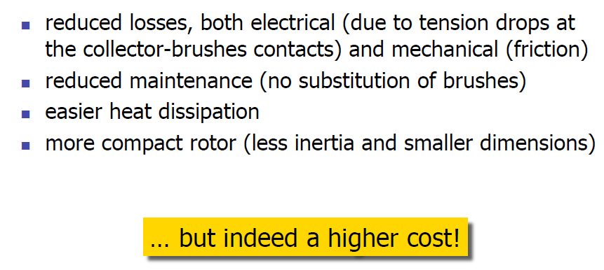
5 Introduction Actuators are the muscles of robots. There are many types of actuators available depending on the load involved. The term load is associated with many factors including force, torque, speed of operation, accuracy, precision and power consumption: 1- Electric Motors Servomotors Stepper motors Direct-drive electric motors 2- Hydraulic actuators 3- Pneumatic actuators 4-Shape memory metal actuators 5- Magnetostrictive actuators. Electromechanical actuators convert electrical energy into mechanical energy. Magnetism is the basis of their principle of operation. They are DC, AC and stepper motors. DC motors require a direct current or voltage source as the input signals. AC motors require an alternating current or voltage source
6 Introduction Stepper motors have capability of achieving precision angular rotation in both directions and are commonly employed to accommodate digital control technology. Hydraulic and pneumatic actuators are under fluid power actuators. Fluid power refers to energy that is transmitted via a fluid under pressure. When a pressure is applied to a confined chamber containing a piston, the piston will exert a force causing a motion. The piston will move if the difference in force across the piston is larger than the total load plus the friction forces. Materials which undergo some sort of transformations through physical interaction, are referred to as active materials. Piezoelectric (voltage-load), shape-memory alloys (react to heat), magnetostrictive are examples of these materials.
7 Introduction Characteristics of actuating systems 1- Weight, Power-to-weight Ratio, Operating pressure Stepper motors are generally heavier than servomotors for the same power. The high the voltage of electric motors, the better power-to-weight ratio. Pneumatic systems delivers the lowest power-to-weight ratio ( psi) Hydraulic systems have the highest power-to-weight ratio ( psi). In these systems, the weight is actually composed of two portions. One is the hydraulic actuators, and the other is the hydraulic power unit (pump, cylinders, rams, reservoirs, filter, and electric motor). If the power unit must also move with the robot, the total power-to-weight ratio will be much less. 2- Stiffness versus Compliance Stiffness is the resistance of a material against deformation. The stiffer the system, the larger the load that is needed to deform it. Conversely, the more compliant the system the easier it deforms under the load. Stiffness is directly related to the modulus of elasticity of the material. Hydraulic systems are very stiff and non-compliant while pneumatic systems are easily compressed and thus are compliant. Stiff systems have a more rapid response to changing loads and pressures and are more accurate. Although stiffness causes a more responsive and more accurate systems, it also creates a danger if all things are not always perfect.
8 Introduction 3- Use of Reduction Gears Hydraulic devices produce very large forces with short stroke. This means that the hydraulic arm may be moved very slightly while delivering its full force. As a result, there is no need to use reduction gear trains to increase the torque and to slow it down to manageable speeds. Electric motors rotate at high speeds (up to many thousands of revolution per minute) and must be used in conjunction with reduction gears to increase torque and reduce rotation speed. This will increase the cost, number of parts, backlash, and inertia of the rotating body.
9 Introduction Now suppose that, through a set of reduction gears with ratio of N, a load with inertia, is connected to a motor with Inertia (including inertia of reduction gears), as shown in Figure (6.1). The torque and speed ratio between the motor and the load will be: Inertia and torque relationship between a motor and a load
10 Introduction

11

12

13
14

15
16

17
18

19
20
21
22

23
24
25 Hydraulic Actuators A hydraulic system generally consists of the following parts: 1. Hydraulic linear or rotary cylinders and rams to provide the force or torque needed to move the joints and are controlled by servo valve or manual valve. 2. A hydraulic pump to provide high pressure fluid to the system 3. Electric motor to operate the hydraulic pump. 4. Cooling system to get rid of heat (cooling fans, radiators, and cooled air). 5. Reservoir to keep fluid supply available to the system. 6. Servo valve which is a very sensitive valve that controls the amount and the rate of the fluid to the cylinders. The servo valve is generally driven by a hydraulic servomotor. 7. Sensors to control the motion of the cylinders (position, velocity, magnetic, touch,..) 8. Connecting hoses to transport the pressurized fluid. 9. Safety check valves, holding valves.
26
27 Hydraulic Actuators Spool Valve Spool valve or pilot valve is a balanced valve, which means that the pressure on the two sides of the spool is equal so a little force can move it, even though it may be under high pressure. When a servomotor is attached to the spool valve to operate it, a servo valve is created. The servo valve and the cylinder together form a hydraulic servomotor. As the spool moves up and down, it opens the supply and return ports through which the fluid travels to the cylinders or is returned to the reservoir. Velocity of the cylinder can be controlled based on the size of the opening of the port. The total travel of the cylinder is controlled based on the length of the time that the port is kept open. Schematic diagram of a spool valve in neutral position
28 Hydraulic Actuators The controller sets the current to the servomotor, as well as the duration the current is applied, to control the position of the spool. The controlling procedure is as follows: Position and velocity should be calculated by the controller. Set the amount of current and its duration to the servomotor. Controlling the position and rate of movement of the spool valve. Controlling the flow and its rate to the cylinder. The cylinder moves the joint. The sensors provide feedback to the controller for accurate and continued control. Schematic diagram of a spool valve in open position. Depending on which ports is open, the direction of motion of the piston will change
29 Hydraulic Actuators Mechanical Feedback Strategy As the desired position for the load is set by the set point lever, say up, the spool valve is opened which will operate the cylinder. This will provide error signal (fluid pressure) to the cylinder. The error signal is integrated by the integrator and the error approaches zero. Schematic diagram of a simple control device with proportional feedback
Thermodynamic efficiency of an actuator that provides the mechanical movement for the driven equipments:
 1. Introduction 1.1. Industry Automation Industry automation is the term that describes a vital development programme of a production community where the project engineers build up automated manufacturing
Sensors Collecting Manufacturing Process Data
 Sensors & Actuators Sensors Collecting Manufacturing Process Data Data must be collected from the manufacturing process Data (commands and instructions) must be communicated to the process Data are of
Schematic Symbols Chart (Design Hydraulic and Pneumatic circits)
") Page 1 of 6 (Home) Symbols / Visit us on: Fluid Power, Automation and Motion Control for all Industries About Us Products Services Catalogs Place an Order Training & Information Contact Us Employee Access
Page 1 of 6 (Home) Symbols / Visit us on: Fluid Power, Automation and Motion Control for all Industries About Us Products Services Catalogs Place an Order Training & Information Contact Us Employee Access
Choosing Between Electromechanical and Fluid Power Linear Actuators in Industrial Systems Design
 Choosing Between Electromechanical and Fluid Power Linear Actuators in Industrial Systems Design James Marek, Business Unit Director, Thomson Systems Thomson Industries, Inc. 540-633-3549 www.thomsonlinear.com
UNIT II Robots Drive Systems and End Effectors Part-A Questions
 UNIT II Robots Drive Systems and End Effectors Part-A Questions 1. Define End effector. End effector is a device that is attached to the end of the wrist arm to perform specific task. 2. Give some examples
Introduction to Process Control Actuators
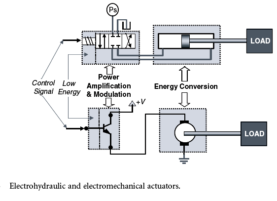
 1 Introduction to Process Control Actuators Actuators are the final elements in a control system. They receive a low power command signal and energy input to amplify the command signal as appropriate to
Chapter 11 SERVO VALVES. Fluid Power Circuits and Controls, John S.Cundiff, 2001
 Chapter 11 SERVO VALVES Fluid Power Circuits and Controls, John S.Cundiff, 2001 Servo valves were developed to facilitate the adjustment of fluid flow based on the changes in the load motion. 1 Typical
Design Aspects of Robot Manipulators
 Design Aspects of Robot Manipulators Dr. Rohan Munasinghe Dept of Electronic and Telecommunication Engineering University of Moratuwa System elements Manipulator (+ proprioceptive sensors) End-effector
Material taken from Fluid Power Circuits and Controls, John S. Cundiff, 2001
 Pressure Control Chapter 3 Material taken from Fluid Power Circuits and Controls, John S. Cundiff, 2001 Introduction Pressure control is a key element in the design of any circuit. Used correctly, it can
Unit 24: Applications of Pneumatics and Hydraulics
 Unit 24: Applications of Pneumatics and Hydraulics Unit code: J/601/1496 QCF level: 4 Credit value: 15 OUTCOME 2 TUTORIAL 4 DIRECTIONAL CONTROL VALVES The material needed for outcome 2 is very extensive
Recognizing and understanding schematic symbols will enable you to comprehend a circuit s function.
 Schematic symbols are used to identify and graphically depict the function of fluid power components. Recognizing and understanding schematic symbols will enable you to comprehend a circuit s function.
Example. Fluid Power. Circuits
 Example Fluid Power Circuits To Enhance Symbol Reading Skills To Work On Circuit Reading Skills With Answers HI LO Pump Circuit 18 A1 B1 17 16 15 13 Set 14 2,000 PSI PG2 Set 500 PSI 12 11 7 8 10 PG1 9
The Secret of Hydraulic Schematics. BTPHydraulics www.iranfluidpower.com
 The Secret of Hydraulic Schematics BTPHydraulics www.iranfluidpower.com www.iranfluidpower.com Table of Contents The Secret to Reading and Interpreting Hydraulic Schematics... 1 Hydraulic System Schematics...
CNC HARDWARE & TOOLING BASICS
 Computer Aided Manufacturing (CAM) CNC HARDWARE & TOOLING BASICS Assoc. Prof. Dr. Tamer S. Mahmoud 1. Parts of CNC Machine Tools Any CNC machine tool essentially consists of the following parts: Part Program,
LINEAR ACTUATORS. Linear Actuators. Linear Actuators. Linear Actuators are Actuators that creates motion in a straight line, as contrasted
 LINEAR ACTUATORS Linear Actuators Linear Actuators Linear Actuators are Actuators that creates motion in a straight line, as contrasted with circular motion of a conventional electric motor. Linear actuators
Manufacturing Equipment Modeling
 QUESTION 1 For a linear axis actuated by an electric motor complete the following: a. Derive a differential equation for the linear axis velocity assuming viscous friction acts on the DC motor shaft, leadscrew,
Robot coined by Karel Capek in a 1921 science-fiction Czech play
 Robotics Robot coined by Karel Capek in a 1921 science-fiction Czech play Definition: A robot is a reprogrammable, multifunctional manipulator designed to move material, parts, tools, or specialized devices
Basic Symbols. Lines. Circular. Square. Diamond. Miscellaneous Symbols. -continuous line - flow line. -dashed line - pilot, drain
 Airline Hydraulic's Main Page Basic Symbols Lines continuous line flow line dashed line pilot, drain envelope long and short dashes around two or more component symbols. Circular Square Diamond large circle
10. CNC Hardware Basics
 CAD/CAM Principles and Applications 10 CNC Hardware Basics 10-1/10-20 by P.N.Rao 10. CNC Hardware Basics 10.1 Structure of CNC machine tools Table 10.1 Some design criteria for CNC machine tool design
Proportional and Servo Valve Technology
 The ability to achieve automated stepless control of pressure and flow rate in fluid power systems has undergone major development in the past twenty-five years. Electrohydraulic servo valves were invented
Unit 24: Applications of Pneumatics and Hydraulics
 Unit 24: Applications of Pneumatics and Hydraulics Unit code: J/601/1496 QCF level: 4 Credit value: 15 OUTCOME 2 TUTORIAL 1 HYDRAULIC PUMPS The material needed for outcome 2 is very extensive so there
Unit 24: Applications of Pneumatics and Hydraulics
 Unit 24: Applications of Pneumatics and Hydraulics Unit code: J/601/1496 QCF level: 4 Credit value: 15 OUTCOME 2 TUTORIAL 3 HYDRAULIC AND PNEUMATIC MOTORS The material needed for outcome 2 is very extensive
Robotics & Automation
 Robotics & Automation Levels: Grades 10-12 Units of Credit: 1.0 CIP Code: 21.0117 Core Code: 38-01-00-00-130 Prerequisite: None Skill Test: 612 COURSE DESCRIPTION Robotics & Automation is a lab-based,
INSTRUMENTATION AND CONTROL TUTORIAL 2 ELECTRIC ACTUATORS
 INSTRUMENTATION AND CONTROL TUTORIAL 2 ELECTRIC ACTUATORS This is a stand alone tutorial on electric motors and actuators. The tutorial is of interest to any student studying control systems and in particular
CIM Computer Integrated Manufacturing
 INDEX CIM IN BASIC CONFIGURATION CIM IN ADVANCED CONFIGURATION CIM IN COMPLETE CONFIGURATION DL CIM A DL CIM B DL CIM C DL CIM C DL CIM B DL CIM A Computer Integrated Manufacturing (CIM) is a method of
HYDRAULIC ARM MODELING VIA MATLAB SIMHYDRAULICS
 Engineering MECHANICS, Vol. 16, 2009, No. 4, p. 287 296 287 HYDRAULIC ARM MODELING VIA MATLAB SIMHYDRAULICS Stanislav Věchet, Jiří Krejsa* System modeling is a vital tool for cost reduction and design
A descriptive definition of valve actuators
 A descriptive definition of valve actuators Abstract A valve actuator is any device that utilizes a source of power to operate a valve. This source of power can be a human being working a manual gearbox
COUNTERBALANCE VALVES
 COUNTERBALANCE VALVES Introduction They are modulating valves which allow free flow into the actuator and then block the reverse flow until they feel a pilot pressure inversely proportional to the load
Hydraulic Control Technology for Wind Turbine Generators
 Industrial Hydraulics Electric Drives and Controls Linear Motion and Assembly Technologies Pneumatics Service Automation Mobile Hydraulics Hydraulic Control Technology for Wind Turbine Generators Extra
AMESim = Advanced Modeling Environment for performing Simulations of engineering systems.
 AMESim AMESim = Advanced Modeling Environment for performing Simulations of engineering systems. AMESim is a 1D lumped parameter time domain simulation platform. AMESim uses symbols to represent individual
Closed-Loop Motion Control Simplifies Non-Destructive Testing
 Closed-Loop Motion Control Simplifies Non-Destructive Testing Repetitive non-destructive testing (NDT) applications abound, and designers should consider using programmable motion controllers to power
Unit 24: Applications of Pneumatics and Hydraulics
 Unit 24: Applications of Pneumatics and Hydraulics Unit code: J/601/1496 QCF level: 4 Credit value: 15 OUTCOME 2 TUTORIAL 2 HYDRAULIC AND PNEUMATIC CYLINDERS The material needed for outcome 2 is very extensive
TECHNICAL INFORMATION Bulletin
 Peerless Pump Company 2005 Dr. M.L. King Jr. Street, P.O. Box 7026, Indianapolis, IN 46207-7026, USA Telephone: (317) 925-9661 Fax: (317) 924-7338 www.peerlesspump.com www.epumpdoctor.com TECHNICAL INFORMATION
Pneumatic control for robotics and industrial automation Author: Naresh Raghavan
 Pneumatic control for robotics and industrial automation Author: Naresh Raghavan Introduction Pneumatic systems form the most primitive and distinct class of mechanical control engineering. They are classified
Frequently Asked Questions
 Frequently Asked Questions System and Valve Basics: 1. Q: What is good cooling coil performance? A: The temperature range is controlled within +/- 0.5 F (0.28 C) off the cooling coil at set point or below.
Quiz On Information Learned From Chapter 1
 Quiz On Information Learned From Chapter 1 1. Most hydraulic circuits are designed by: A. mechanical engineers. B. fluid power engineers. C. fluid power distributor salesmen. 2. Atmospheric pressure at
UNIT 1 INTRODUCTION TO NC MACHINE TOOLS
 UNIT 1 INTRODUCTION TO NC MACHINE TOOLS Structure 1.1 Introduction Objectives 1.2 NC Machines 1.2.1 Types of NC Machine 1.2.2 Controlled Axes 1.2.3 Basic Components of NC Machines 1.2.4 Problems with Conventional
Daniel. Liquid Control Valves Technical Guide. Technical Guide DAN-LIQ-TG-44-rev0813. DAN-LIQ-TG-44-rev0208. February 2008.
 DAN-LIQ-TG-44-rev0208 February 2008 Daniel Liquid Control Valves Technical Guide www.daniel.com Daniel Measurement and Control Theory, Principle of Operation and Applications This brochure has been prepared
THE STRAIN GAGE PRESSURE TRANSDUCER
 THE STRAIN GAGE PRESSURE TRANSDUCER Pressure transducers use a variety of sensing devices to provide an electrical output proportional to applied pressure. The sensing device employed in the transducers
MONO BLOCK DIRECTIONAL CONTROL VALVE TS1120TSLB
 MONO BLOCK DIRECTIONAL CONTROL VALVE TS112TSLB TS TS212TSTSJB P T TS312TSDTSTKJ TS112TSJB FEATURES: O RG PORTS to eliminate leakage. POWER BEYOND CAPABILITY to fit your multi valve circuits. BUILT ANTI-DROP
The Assembly Automation Industry
 System Solutions For The Assembly Automation Industry Your Resource For Motion Control Components, Systems and Solutions Assembly Automation Industry: A Focus Parker means components, systems and partnerships
hance the application of specific components, such as pumps, motors, accumulators, filters, and airline lubricators.
 Basic circuits Using schematic symbols as building blocks, you can construct a functional diagram showing piping arragnements and operation of any hydraulic or pneumatic circuit. hance the application
What Is an Electric Motor? How Does a Rotation Sensor Work?
 What Is an Electric Motor? How Does a Rotation Sensor Work? Electric Motors Pre-Quiz 1. What is an electric motor? 2. Name two applications (things) you use every day that use electric motors. 3. How does
Mechanical Systems. Grade 8 Unit 4 Test. 1. A wheelbarrow is an example of what simple machine? Class 1 lever. Class 2 lever.
 Mechanical Systems Grade 8 Unit 4 Test Student Class 1. A wheelbarrow is an example of what simple machine? D Wheel and Axle 2. A hockey stick is an example of what simple machine? D Inclined plane 3.
Introduction to Robotics Analysis, Systems, Applications
 Introduction to Robotics Analysis, Systems, Applications Saeed B. Niku Mechanical Engineering Department California Polytechnic State University San Luis Obispo Technische Urw/carsMt Darmstadt FACHBEREfCH
SERVOMECH Linear Actuators
 . SERVOMECH Linear actuators SERVOMECH mechanical linear actuators are motorised mechanical cylinders able to transform the rotary motion of a motor into the linear motion of a push rod. They are designed
Chapter 5. Components, Symbols, and Circuitry of Air-Conditioning Wiring Diagrams
 Chapter 5 Components, Symbols, and Circuitry of Air-Conditioning Wiring Diagrams Objectives Upon completion of this course, you will be able to: Explain what electrical loads are and their general purpose
Pump ED 101. Positive Displacement Pumps. Part I Reciprocating Pumps
 Pump ED 101 Positive Displacement Pumps Part I Reciprocating Pumps Joe Evans, Ph.D http://www.pumped101.com There are many pump designs that fall into the positive displacement category but, for the most
Why and How we Use Capacity Control
 Why and How we Use Capacity Control On refrigeration and air conditioning applications where the load may vary over a wide range, due to lighting, occupancy, product loading, ambient weather variations,
BRAKE SYSTEM DESIGN AND THEORY
 RAKE SYSTEM DESIGN AND THEORY Aircraft brake systems perform multiple functions. They must be able to hold the aircraft back at full static engine run-up, provide adequate control during ground taxi operations,
Alternative Linear Motion Systems. Iron Core Linear Motors
 Alternative Linear Motion Systems ME EN 7960 Precision Machine Design Topic 5 ME EN 7960 Precision Machine Design Alternative Linear Motion Systems 5-1 Iron Core Linear Motors Provide actuation forces
Chapter 19 - Common Rail High Pressure Fuel Injection Systems
 Chapter 19 - Common Rail High Pressure Fuel Injection Systems Diesel Engine Technology For Automotive Technicians Understanding & Servicing Contemporary Clean Diesel Technology What is Common Rail? Common
1115 4G SERIES GOVERNOR. 4-20 ma ANALOGUE DIGITAL SPEED SETTING
 1115 4G SERIES GOVERNOR with 4-20 ma ANALOGUE & DIGITAL SPEED SETTING PO Box 28, 9300AA Roden, The Netherlands Tel: +31 505019888 Fax: +31 505013618 E-mail: [email protected] 1115 4G
Index 11.1. Page. Pumping Systems...11.2-11.4 Intensifiers...11.5 Gas Boosters...11.6-11.7 High Pressure Generators...11.8-11.9
 Pumping Systems, Intensifiers, Gas Boosters and High Pressure Generators High Pressure Equipment Company produces a number of components and systems for general industrial, elevated pressure applications.
Learning Systems Software Simulation
 Learning Systems Software Simulation EasyVeep PLC controls and technology training FluidSIM Fluid Power training aid for instructors and design tool for engineers COSIMIR PLC 3D simulation tool for practical
Flow Charts and Servomotors (background to Lab #2) Things to learn about: flow charts for design. MECH452 2014 Lecture #2 flow charts & servos rev2
 Things to learn about: flow charts for design. MECH452 2014 Lecture #2 flow charts & servos rev2") MECH 452 Lecture #2 Flow Charts and Servomotors (background to Lab #2) 1 2 Handout #2 (highlights, questions) Things to learn about: flow charts for design Only 5 symbols (subroutine not shown) Flow charts
MECH 452 Lecture #2 Flow Charts and Servomotors (background to Lab #2) 1 2 Handout #2 (highlights, questions) Things to learn about: flow charts for design Only 5 symbols (subroutine not shown) Flow charts
PART 2 FORKLIFT HYDRAULIC SYSTEM
 PART 2 FORKLIFT HYDRAULIC SYSTEM Chapter 1 Description and Operation Component Locations & Circuit Layouts 1 Hydraulic Pump 11 Control Valve 14 Valve Section Oil Flows 15 Anti-Cavitation Valve 22 Velocity
Motor Selection and Sizing
 Motor Selection and Sizing Motor Selection With each application, the drive system requirements greatly vary. In order to accommodate this variety of needs, Aerotech offers five types of motors. Motors
F output. F input. F = Force in Newtons ( N ) d output. d = distance ( m )
 d output. d = distance ( m )") Mechanical Advantage, Speed Ratio, Work and Efficiency Machines Make Work Easier Machines help people do things that they normally couldn t do on their own. Mechanical Advantage A machine makes work easier
Mechanical Advantage, Speed Ratio, Work and Efficiency Machines Make Work Easier Machines help people do things that they normally couldn t do on their own. Mechanical Advantage A machine makes work easier
10 tips for servos and steppers a simple guide
 10 tips for servos and steppers a simple guide What are the basic application differences between servos and steppers? Where would you choose one over the other? This short 10 point guide, offers a simple
Pure Efficiency. C.C.I.A.A.: N REA. 0195268 Cod. Fiscale e P. IVA: 00483230173 Capitale Sociale versato 100.000,00
 Pure Efficiency. The need to significantly reduce the production costs to remain competitive on the global market and the requirement to control and lessen the environmental impact of all activities are
Tiguan Haldex All-Wheel Drive
 Service Training Self Study Program 861803 Tiguan Haldex All-Wheel Drive Volkswagen of America, Inc. Volkswagen Academy Printed in U.S.A. Printed 3/2008 Course Number 861803 2008 Volkswagen of America,
EDUMECH Mechatronic Instructional Systems. Ball on Beam System
 EDUMECH Mechatronic Instructional Systems Ball on Beam System Product of Shandor Motion Systems Written by Robert Hirsch Ph.D. 998-9 All Rights Reserved. 999 Shandor Motion Systems, Ball on Beam Instructional
TOYOTA ELECTRONIC CONTROL TRANSMISSION
 Electronic Control Transmission (ECT) The Electronic Control Transmission is an automatic transmission which uses modern electronic control technologies to control the transmission. The transmission itself,
MONO BLOCK DIRECTIONAL CONTROL VALVE TS
 SHIPPING: 2332 S 25TH STREET (ZIP 6815) MAILING: P.O. BOX #669 OMAHA, NE 6816 PHONE: (42) 344-4434 FAX: (42) 341-5419 HTTP://WWW.BRAND-HYD.COM MONO BLOCK DIRECTIONAL CONTROL VALVE TS TS312TSDTSTKJB TS2
ELECTROMECHANICAL ACTUATION FOR LAUNCH VECHICLES
 ELECTROMECHANICAL ACTUATION FOR LAUNCH VECHICLES Presented By: Mark A. Davis Moog Inc. 37th AIAA/ASME/SAE/ASEE Joint Propulsion Conference Salt Lake City, Utah July 10, 2001 Introduction This paper describes
INSTRUMENTATION AND CONTROL TUTORIAL 3 SIGNAL PROCESSORS AND RECEIVERS
 INSTRUMENTATION AND CONTROL TUTORIAL 3 SIGNAL PROCESSORS AND RECEIVERS This tutorial provides an overview of signal processing and conditioning for use in instrumentation and automatic control systems.
McCAULEY CONSTANT SPEED PROPELLER GOVERNING SYSTEM
 Professor Von Kliptip Answers Your Questions About The McCAULEY CONSTANT SPEED PROPELLER GOVERNING SYSTEM FOR NON-COUNTERWEIGHTED PRESSURE TO INCREASE PITCH PROPELLERS ON TYPICAL SINGLE ENGINE AIRCRAFT
Suspension and Steering Systems Operation. The Steering/Suspension System (Overview)
") Suspension and Steering Systems Operation Below is an overview of the suspension and steering systems The Steering/Suspension System (Overview) "Suspension," when discussing cars, refers to the use of
Suspension and Steering Systems Operation Below is an overview of the suspension and steering systems The Steering/Suspension System (Overview) "Suspension," when discussing cars, refers to the use of
Hydraulic Troubleshooting PRESENTED BY
 Hydraulic Troubleshooting PRESENTED BY NORMAN KRONOWITZ Introduction Welcome to the CMA/Flodyne/Hydradyne s Hydraulic Troubleshooting presentation. We will introduce many aspects of troubleshooting hydraulic
Industrial Steam System Process Control Schemes
 Industrial Steam System Process Control Schemes This paper was developed to provide a basic understanding of the different process control schemes used in a typical steam system. This is however a fundamental
Plastic Injection Molding
 Training Objective After watching this video and reviewing the printed material, the student/trainee will understand the principles and physical operations of the plastic injection molding process. An
When looking at machine tools, the details of the installed drive technology usually
 Multiple Solutions: Different Drive Concepts for Machine Tools When looking at machine tools, the details of the installed drive technology usually remain concealed. There are, in principle, various possibilities
MASTER CYLINDER. Section 2. Master Cylinder. Tandem Master Cylinder. Master Cylinder
 MASTER CYLINDER Master Cylinder The master cylinder converts the motion of the brake pedal into hydraulic pressure. It consists of the reservoir tank, which contains the brake fluid; and the piston and
Extremely compact in size to allow direct flange-mounting on vehicle engine or gearbox PTOs.
 TXV - Presentation pumps with Load Sensing control variable displacement piston pumps ADVANTAGES pumps are variable displacement with pressure-flow control called Load Sensing. They self-regulate to give
Test Code: 8094 / Version 1
 Blueprint Electromechanical Engineering Technology PA Test Code: 8094 / Version 1 Copyright 2014. All Rights Reserved. General Assessment Information Electromechanical Engineering Technology PA Blueprint
Chapter 2 Fundamentals of Robotics
 This sample chapter is for review purposes only. Copyright The Goodheart-Willcox Co., Inc. All rights reserved. Chapter 2 Fundamentals of Robotics Chapter Topics 2.1 Parts of a Robot 2.2 Degrees of Freedom
Steering unit. Table of contents. Features RE 11872/05.06. Type LAGL. Frame sizes 500 to 1000 Component series 1X Maximum flow 80 l/min
 Steering unit RE 11872/05.06 /10 Type LAGL Frame sizes 500 to 1000 Component series 1X Maximum flow 80 l/min H7375 Table of contents Contents Page Features 1 Ordering code 2 Function, section 3 Device
Synchronous motor. Type. Non-excited motors
 Synchronous motor A synchronous electric motor is an AC motor in which the rotation rate of the shaft is synchronized with the frequency of the AC supply current; the rotation period is exactly equal to
Fig 1 Power Transmission system of Tractor
 POWER TRANSMISSION SYSTEM Transmission is a speed reducing mechanism, equipped with several gears (Fig. 1). It may be called a sequence of gears and shafts, through which the engine power is transmitted
A/C refrigerant system, overview
 Page 1 of 19 87-18 A/C refrigerant system, overview A/C refrigerant system, identification Typical A/C refrigerant system with expansion valve and receiver drier 1 - Evaporator 2 - Expansion valve 3 -
Cane Creek Double Barrel Instructions
 Cane Creek Double Barrel Instructions Congratulations on your purchase of the Cane Creek Double Barrel (CCDB) rear shock. Developed in partnership with Öhlins Racing, the Double Barrel brings revolutionary
Hydraulic Control Solutions
 Hydraulic Control Solutions Vexve s Hydrox hydraulic control solutions are suitable for even the most challenging installation sites and conditions. Specifically designed for district heating and district
Centrifugal Fans and Pumps are sized to meet the maximum
 Fans and Pumps are sized to meet the maximum flow rate required by the system. System conditions frequently require reducing the flow rate. Throttling and bypass devices dampers and valves are installed
Introduction to Linear Actuators: Precision Linear Motion Accomplished Easily and Economically
 Introduction to Linear Actuators: Precision Linear Motion Accomplished Easily and Economically Part 1 of 2 When students are trained in classic mechanical engineering, they are taught to construct a system
MOTION CONTROL. Special issue on. A helping hand from robotics, page 56 PIEZO-DRIVEN STAGE MAKES MOVES IN MICROMETERS, PAGE 18
 PIEZO-DRIVEN STAGE MAKES MOVES IN MICROMETERS, PAGE 18 Special issue on MOTION CONTROL A helping hand from robotics, page 56 Thwarting the time bandits: How to overcome actuator delays, page 64 THE BASICS
How to Turn an AC Induction Motor Into a DC Motor (A Matter of Perspective) Steve Bowling Application Segments Engineer Microchip Technology, Inc.
 Steve Bowling Application Segments Engineer Microchip Technology, Inc.") 1 How to Turn an AC Induction Motor Into a DC Motor (A Matter of Perspective) Steve Bowling Application Segments Engineer Microchip Technology, Inc. The territory of high-performance motor control has
1 How to Turn an AC Induction Motor Into a DC Motor (A Matter of Perspective) Steve Bowling Application Segments Engineer Microchip Technology, Inc. The territory of high-performance motor control has
The Electrical Properties of Materials: Resistivity
 The Electrical Properties of Materials: Resistivity 1 Objectives 1. To understand the properties of resistance and resistivity in conductors, 2. To measure the resistivity and temperature coefficient of
Simple Machines. Figure 2: Basic design for a mousetrap vehicle
 Mousetrap Vehicles Figure 1: This sample mousetrap-powered vehicle has a large drive wheel and a small axle. The vehicle will move slowly and travel a long distance for each turn of the wheel. 1 People
ENERGY TRANSFER SYSTEMS AND THEIR DYNAMIC ANALYSIS
 ENERGY TRANSFER SYSTEMS AND THEIR DYNAMIC ANALYSIS Many mechanical energy systems are devoted to transfer of energy between two points: the source or prime mover (input) and the load (output). For chemical
WHITE PAPER. DC Motors Explained. DC Motors Explained: White Paper, Title Page
 DC Motors Explained: White Paper, Title Page DC Motors Explained By Joe Kimbrell, Product Manager, Drives, Motors & Motion, AutomationDirect DC Motors Explained: White Paper, pg. 2 How many types of DC
Selecting and Sizing Ball Screw Drives
 Selecting and Sizing Ball Screw Drives Jeff G. Johnson, Product Engineer Thomson Industries, Inc. Wood Dale, IL 540-633-3549 www.thomsonlinear.com [email protected] Fig 1: Ball screw drive is a
Fault codes DM1. Industrial engines DC09, DC13, DC16. Marine engines DI09, DI13, DI16 INSTALLATION MANUAL. 03:10 Issue 5.0 en-gb 1
 Fault codes DM1 Industrial engines DC09, DC13, DC16 Marine engines DI09, DI13, DI16 03:10 Issue 5.0 en-gb 1 DM1...3 Abbreviations...3 Fault type identifier...3...4 03:10 Issue 5.0 en-gb 2 DM1 DM1 Fault
WHAT YOU DON T KNOW ABOUT ACCUMULATORS CAN KILL YOU!
 WHAT YOU DON T KNOW ABOUT ACCUMULATORS CAN KILL YOU! Atlanta (Monroe) GA 770-267-3787 [email protected] www.gpmhydraulic.com What You Don t Know About Hydraulic Accumulators Can Kill You TABLE OF CONTENTS
Pneumatically Driven Robot System with Force Perception for Minimally Invasive Surgery
 Pneumatically Driven Robot System with Force Perception for Minimally Invasive Surgery Tokyo Institute of Technology Kotaro Tadano Daisuke Haraguchi Kenji Kawashima Research Overview on Surgical Robots
Motors and Inverters for Environmentally Friendly Industrial Equipment
 Motors and Inverters for Environmentally Friendly Industrial Equipment 238 Motors and Inverters for Environmentally Friendly Industrial Equipment Takatoshi Sakai Hideharu Tanaka Yuji Tanaka Katsuyuki Utatsu
SOLID MECHANICS TUTORIAL MECHANISMS KINEMATICS - VELOCITY AND ACCELERATION DIAGRAMS
 SOLID MECHANICS TUTORIAL MECHANISMS KINEMATICS - VELOCITY AND ACCELERATION DIAGRAMS This work covers elements of the syllabus for the Engineering Council exams C105 Mechanical and Structural Engineering
PSA-G Precision Gearheads
 Zero Backlash High Torque PSA-G Precision Gearheads High Precision When your applications require accurate positioning and precise motion control, Harmonic Drive Technologies offers the perfect solution.
Servo Info and Centering
 Info and Centering A servo is a mechanical motorized device that can be instructed to move the output shaft attached to a servo wheel or arm to a specified position. Inside the servo box is a DC motor
dspace DSP DS-1104 based State Observer Design for Position Control of DC Servo Motor
 dspace DSP DS-1104 based State Observer Design for Position Control of DC Servo Motor Jaswandi Sawant, Divyesh Ginoya Department of Instrumentation and control, College of Engineering, Pune. ABSTRACT This