POST HOLE DIGGER. Operation, Service & Parts Manual For Models D20 & D40. FORM: D20_40DigRev.QXD
|
|
|
- Shanon James
- 7 years ago
- Views:
Transcription
1 POST HOLE DIGGER Operation, Service & Parts Manual For Models D20 & D40 FORM: D20_40DigRev.QXD September 2006 Revised August 2009

2 TABLE OF CONTENTS Introduction Preparation Safety Information Assembly Instructions Point Hitch Adjustments Operating Digger Lubrication & General Maintenance Components D Components D Gearbox Breakdown Driveline Breakdown Eurocardan Driveline Breakdown ITG Limited Warranty

3 INTRODUCTION Thank you for purchasing a Gearmore Digger. In order to be able to safely and properly operate this digger, it will be necessary for you to familiarize yourself with the contents of the entire manual before you attempt to assemble and operate your digger. Please read all safety and assembly instructions before attempting to operate digger. Date of Purchase: Model Number: Serial Number Page 1

4 PREPARATION WARNING To prevent possible personal injury or death during assembly, installation, operation, adjustment, or removal of implement: DO NOT wear loose clothing, always wear gloves and safety glasses or face shield. Keep other persons a minimum of twenty-five feet (25') away from any unit under power. READ THIS BEFORE OPERATING DIGGER TRAINING: Know your controls. Read this operator's manual and the manual provided with your tractor. Learn how to stop the tractor, engine and digger quickly, in case of an emergency. DO NOT allow children to operate machine, or adults to operate it without proper instructions. PREPARATION: Clear area of debris. Never permit any person other than the operator to ride on board the tractor at any time. DO NOT allow riders on digger at any time. Operate only in daylight or good artificial light. Ensure all safety shielding is properly installed. Always wear relatively tight and belted clothing when operating digger. Loose clothing should not be worn, as it could get caught in the moving parts or controls. Page 2

5 SAFETY INFORMATION OPERATIONAL SAFETY: Guards and safety shields are for your protection. DO NOT operate equipment unless they are in place. Always operate tractor PTO (power take-off) at recommended RPM (revolutions per minute). Disengage tractor PTO and shift into neutral before attempting to start engine. Read and observe all safety decals on the tractor and digger. NEVER allow anyone within 25' of machine while it is in operation. Do not stop or start suddenly when going uphill or downhill. Avoid operation on steep slopes. Be alert for holes in terrain and other hidden hazards. Always drive slowly over rough ground. Reduce speed on slopes and in sharp turns to prevent tipping or loss of control. Be careful when changing direction on slopes. Stop digger and tractor immediately upon striking an obstruction. Turn off engine, inspect digger, and repair any damage before resuming operation. Disengage power to digger and stop engine before dismounting from tractor, making any repairs or adjustments, transporting, or unclogging digger. Take all possible precautions when leaving tractor unattended. Disengage PTO, lower digger, shift into neutral, set parking brake, stop engine, and remove key from ignition. Front tractor weights or front tire ballast should be used to enhance front end stability on small tractors. Check to make sure PTO is properly connected and that the driveline is correct to prevent bottoming out or pulling apart during the full lift range of the hitch. This implement is designed for a one-man operation. It is the responsibility of the tractor operator to see that no one is in the proximity of the implement when it is started. DO NOT operate the implement with another person within 25' of the implement, PTO drive, or auger. Page 3

6 ASSEMBLY INSTRUCTIONS The Gearmore Diggers are shipped disassembled in four (4) pieces. 1. Gearbox and auger assembly. 2. Driveshaft assembly with pins and operating instructions packet. 3. The yoke assembly. 4. The boom assembly. Please assemble in the following manner: 1. Attach end of boom to upper 3-point link bracket of the tractor. 2. Attach yoke lift pins into bottom lift arms of tractor. Attach with lynch pins (not supplied). 3. Bolt yoke to boom with 5/8" x 2 1/2" grade 5 bolt (supplied). 4. Raise gearbox assembly up and attach it to the boom with the supplied pin, fasten into place with two cotter pins. 5. Slide driveshaft onto input shaft of gearbox and secure with 3/8" x 2 1/4" grade 2 shear bolt. 6. Install safety roll pin on implement yoke. This will prevent driveshaft from coming off input shaft if shear bolt shears. 7. Install input shaft shield onto gearbox. 8. Install other end of driveshaft to tractor PTO. Raise and lower digger assembly to verify driveshaft is not bottoming out or pulling apart during the full lift range of the hitch. 9. Slide auger adapter shield onto auger to be used. 10. Attach auger to output shaft using 1/2" x 3" grade 2 bolt. 11. Make sure all bolts and pins are in place and secure before operating digger. Page 4

7 3-POINT HITCH ADJUSTMENTS The average operating range of the digger should be between 5" and 65" above the ground level. It is recommended that the 3-point hitch be adjusted toward the minimum required operating range, due to the fact that the greater the operating range, the less force there is available for raising the auger in difficult soil conditions. CAUTION Any time an adjustment is made to the 3-point hitch, reference should be made to the 3-point hitch section of the tractor operator's manual. After any adjustments, the digger should be carefully raised and lowered through its operating range and checked for interference. To change vertical limits of the digger (transport height and digging depth). 1. Attach front end of boom to a hole in the upper link bracket. Upper holes will lower the digger; lower holes will raise the digger. 2. Attach yoke to one of the other existing holes on the boom. Front holes usually increase range; rear holes decrease range. 3. Check tractor hydraulic system to be sure it is raising and lowering to its maximum and minimum recommended heights. Transport height and digging depth can be limited by adjusting lift control handle limit stops. 4. If the front end of the boom strikes some part of the tractor when digger is raised or lowered: a. Make adjustments under Ref. #1. b. If at all possible, relocate or adjust the part of the tractor that is causing the interference. 5. If the tractor has difficulty raising the digger, decrease the lift range. 6. If the tractor hitch raises or lowers rapidly during hydraulic functions, refer to hydraulic adjustment section of the tractor manual. Page 5

8 OPERATING DIGGER WARNING Never operate digger without gloves and eye protection. Keep other persons a minimum of twenty-five feet (25') away from the digger operation. TO OPERATE DIGGER: 1. With your digger correctly assembled and attached to the tractor, engage the tractor PTO at idling speed to give the digger a test run. Then disengage tractor PTO. 2. Place the auger at a vertical position at the desired location of the first hole. 3. Set tractor brake to hold the tractor at the correct position and to prevent damage to the digger. 4. Make sure gloves are on, eye protection is in place, and that nobody is within twenty-five feet (25') of the operation. Engage PTO with the engine at a little more than idle (this speed will depend on soil conditions and experience will help determine proper speed). 5. Slowly lower digger to the ground. After the auger goes a foot or so into the ground, raise auger almost out of the hole, this allows the auger to clean itself of loose soil. Then drill deeper and raise the auger again. Repeat this procedure until the desired hole depth is reached. 6. When desired hole depth is reached, disengage PTO and raise auger from the hole. For tractors that require PTO engagement to produce lifting power, allow auger to turn at idle while raising it from the hole. 7. If shear bolt breaks: a. Shut off tractor engine and allow PTO shaft to come to a complete stop. b. Remove broken shear bolt. c. Install new shear bolt (part #600518), then tighten the shear bolt nut securely. 8. If auger becomes lodged on an obstruction under ground, shut off PTO and tractor engine. Turn the auger several revolutions in reverse. Never attempt to use hydraulic lift of tractor to dislodge auger. Page 6
 of the operation.")
9 LUBRICATION GEARBOX - Fill gearbox with gear oil. Use SAE #140 multigear lubricant or equivalent. Gear oil should be changed after 500 hours of use. DRIVESHAFT - Grease both cross & bearing and shear pin yoke. After that grease every 8 hours of use. It is also necessary, from time to time, to untelescope the driveshaft to clean and re-grease tubing. GENERAL MAINTENANCE Carefully follow all instructions as stated in this operator's manual, this includes safety, assembly, 3-point hitch adjustments, operation, lubrication, and maintenance of the digger. 1. Check bolts, nuts, cotter pins, etc. for tightness. 2. Check auger daily for loose, worn or broken teeth or points. 3. Replace, immediately, any damaged or worn parts. 4. Check lubrication - see lubrication section. IMPORTANT NOTICE: Due to the exceptionally long travel of the hitch arms on some tractors, extreme caution should be taken that you do not lift and operate the digger at too high of an angle. Also, do not have PTO engaged when moving from hole to hole. Failure to follow these procedures can damage the digger and/or tractor. Page 7

10 COMPONENTS FOR D20 DIGGER Page 8

11 COMPONENTS FOR D20 DIGGER REF# QTY. PART NO. DESCRIPTION Gearbox, Complete - Comer Gearbox, Complete - ITG Boom Lift Bracket Pin w/cotter Pin, Gearbox to Boom (7/8" x 6") Lift Bracket Bolt 5/8" x 2 1/2" Auger Adapter Shield Gearbox Shield, Input Shaft Driveline Bolt 3/8" x 2 1/4" Grade Auger Bolt 1/2" x 3" 620, 920, & 1220 Augers 10 As Req'd Tooth For 620, 920 & As Req'd Tooth, Hardfaced for 920 & Point, Auger 12 As Req'd 620 6" Auger 13 As Req'd 920 9" Auger 14 As Req'd " Auger Page 9

12 COMPONENTS FOR D40 DIGGER Page 10
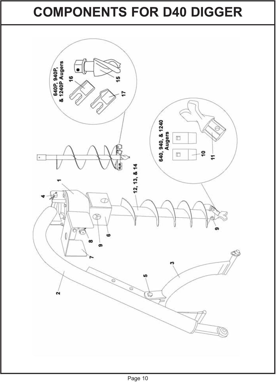
13 COMPONENTS FOR D40 DIGGER REF# QTY. PART NO. DESCRIPTION Gearbox, Complete - Comer Gearbox, Complete - ITG Boom Lift Bracket Pin w/cotter Pin, Gearbox to Boom (7/8" x 7") Lift Bracket Bolt 5/8" x 2 1/2" Auger Adapter Shield Gearbox Shield, Input Shaft /8" x 2 1/4" Grade 2 Bolt Auger Bolt 1/2" x 3" 640, 940, & 1240 Augers 10 As Req'd Tooth For 640, 940 & As Req'd Tooth, Hardfaced for 940 & Point, Auger 12 As Req'd 640 6" Auger 13 As Req'd 940 9" Auger 14 As Req'd " Auger 640P, 940P, & 1240P Augers Point, Auger 16 As Req'd 35 Tooth, Dirt 17 As Req'd 37 Tooth, Gage 18 As Req'd 640P 6" Pengo Auger 19 As Req'd 940P 9" Pengo Auger 20 As Req'd 1240P 12" Pengo Auger Page 11

14 GEARBOX BREAKDOWN REF # QTY. PART NUMBER DESCRIPTION Housing (18-013) Lockwasher (07-001) Cap Screw M10 x 30 x 1.75 (06-003) Pipe Plug 1/2" (09-002) Pin, Hinge 7/8" x 8" Cotter Pin Top Cap (20-014) 8 As Req'd Top Gasket.30 (08-021) 9 As Req'd Top Gasket.25 (08-022) 10 As Req'd Top Gasket.40 (08-023) Bearing Spacer (10-008) Retaining Ring (21-004) Input Seal (05-010) Pinion 11T w/shaft (03-033) Bearing 207 (04-004) Retaining Ring (21-006) Output Seal 50 x 70 x 10 (05-008) Output Shaft (02-029) Taper Bearing Assembly 7210 (04-011) Outer Bearing Spacer (10-011) Retaining Ring (21-001) 22 As Req'd Gear Adj. Shim.30 (17-002) 23 As Req'd Gear Adj. Shim.50 (17-003) Ring Gear 33T (03-032) Set Collar 7/8" Page 12
 11 1 682-111 Bearing Spacer (10-008) 12 1 682-112 Retaining Ring (21-004) 13 1 682-113 Input Seal (05-010) 14 1 682-114 Pinion 11T w/shaft (03-033) 15 2 682-115 Bearing 207 (04-004) 16 1")
15 DRIVELINE BREAKDOWN - (EUROCARDAN) (Yellow Shield) REF # QTY. PART NO. DESCRIPTION Driveline Complete (Eurocardan) Yoke Assembly 1 3/8" x 6 Sp Tractor End Repair Kit #4 Metric Decal, Warning Yoke 1 1/4" Rnd Implement End Tube Bearing Lock Outer Tube Rigid Cone Cone, Standard Stop Rotation Pin Anti-Rotation Chain Soft Cone Inner Tube Rigid Cone Tube Bearing Complete Shield Page 13

16 DRIVELINE BREAKDOWN - (ITG) (Black Shield) REF # QTY. PART NO. DESCRIPTION Driveline Complete (ITG) Yoke Assembly 1 3/8" x 6 Sp Tractor End Grease Zerk M6 x Yoke 1 1/4" Round Bore Imp. End Cross Kit Inner Tube & Yoke Collar Kit Warning Label Outer Tube & Yoke Complete Shield Shear Bolt 2 1/4" (not shown) /4-20x1/2 Set Screw (not shown) Outer Tube Bearing Lock Outer Tube Rigid Cone Cone, Standard Locking Pin Anti-Rotation Chain Soft Cone Inner Tube Rigid Cone Inner Tube Bearing Lock Page 14
 11 1 1/4-20x1/2 Set Screw (not shown) 12 1 612180 Outer Tube Bearing Lock - 04-043 13 1 612174 Outer Tube Rigid Cone - 24-014 14 1 612178")
17 LIMITED WARRANTY GEARMORE, INC., warrants each new Gearmore product to be free from defects in material and workmanship for a period of twelve (12) months from date of purchase to the original purchaser. This warranty shall not apply to implements or parts that have been subject to misuse, negligence, accident, or that have been altered in any way. Our obligation shall be limited to repairing or replacement of any part, provided that such part is returned within thirty (30) days from date of failure to Gearmore through the dealer from whom the purchase was made, transportation charges prepaid. This warranty shall not be interpreted to render us liable for injury or damages of any kind or nature, direct, consequential or contingent, to person or property. This warranty does not extend to loss of crops, loss because of delay in harvesting or any other expenses, for any other reasons. Gearmore in no way warranties engines, tires, or other trade accessories, since these items are warranted separately by these respective manufacturers. Gearmore reserves the right to make improvements in design or changes in specification at any time, without incurring any obligations to owners or units previously sold. GEARMORE, INC Benson Ave. Chino, CA Always refer to and heed machine operating warning decals on machine. The serial number of this product is stored in our computer database, thus submitting a warranty registration card is not required. Page 15
 days from date of failure to Gearmore through the dealer from whom the")
TRACTOR QUICK HITCH CATEGORY I
 TRACTOR QUICK HITCH CATEGORY I Assembly, Operation & Parts Manual January 2005 Form: Quickhitch.PM7 SAFETY INFORMATION To avoid accident or injury, do not allow anyone to operate this equipment without
Operator s Manual POST HOLE DIGGER ACCESSORIES DOWN FORCE KIT. 5BPPHD002 (fits models PHD300 & 400) 5BPPHD005 (fits model PHD200) HOOKUP STAND
 5BPPHD005 (fits model PHD200) HOOKUP STAND") olqljb`= =rp^ Operator s Manual POST HOLE DIGGER ACCESSORIES DOWN FORCE KIT 5BPPHD00 (fits models PHD300 & 400) 5BPPHD005 (fits model PHD00) HOOKUP STAND 5BP009985 (fits models PHD00, 00, 300 & 400) POSITIONING
olqljb`= =rp^ Operator s Manual POST HOLE DIGGER ACCESSORIES DOWN FORCE KIT 5BPPHD00 (fits models PHD300 & 400) 5BPPHD005 (fits model PHD00) HOOKUP STAND 5BP009985 (fits models PHD00, 00, 300 & 400) POSITIONING
1000-LB. TRAILER JACK OWNER S MANUAL
 1000-LB. TRAILER JACK OWNER S MANUAL WARNING: Read carefully and understand all INSTRUCTIONS before operating. Failure to follow the safety rules and other basic safety precautions may result in serious
Model 854/856. Operating and Assembly Manual. Palmor Products Inc. 5225 Serum Plant Road Thorntown, IN 46071
 Model 854/856 Operating and Assembly Manual Palmor Products Inc. 55 Serum Plant Road Thorntown, IN 46071 3/31/2015 SAFETY RULES Remember, any power equipment can cause injury if operated improperly or
Table of Contents WARNING SYMBOLS AND DEFINITIONS
 Table of Contents SAFETY INSTALLATION OPERATION MAINTENANCE Safety... 2 Specifications... 4 Installation... 5 Operation... 8 WARNING SYMBOLS AND DEFINITIONS Maintenance... 9 Parts List and Assembly Diagram...
SE-100-1, SE-200-1, SE-500-1, and SE-1000-1 AIR CHAMP PRODUCTS. User Manual SE BRAKE MODELS: (i) MTY (81) 83 54 10 18 ventas@industrialmagza.
 MTY (81) 83 54 10 18 ventas@industrialmagza.") AIR CHAMP PRODUCTS User Manual SE BRAKE MODELS: SE-00-, SE-200-, SE-500-, and SE-000- (i) FORM NO. L-20084-E-040 In accordance with Nexen s established policy of constant product improvement, the specifications
AIR CHAMP PRODUCTS User Manual SE BRAKE MODELS: SE-00-, SE-200-, SE-500-, and SE-000- (i) FORM NO. L-20084-E-040 In accordance with Nexen s established policy of constant product improvement, the specifications
EXCAVATOR SAFETY TRAINING
 EXCAVATOR SAFETY TRAINING INSPECTION CHECKLIST INSPECTION AREA INSPECTION RESULTS Sat. Unsat. N/A Comments Carrier & Car Body Rotation system Tracks Rollers Frame, welds, bolts Drive system Upper Structure
2
 10 MECHANICAL DRIVE SWING AWAY AUGER PARTS LIST SERIAL NOS. 70000-74773 1 2 # PART # DESCRIPTION 1 B198362 Boot Access Cover 2 B030500 Side Wind Jack 3 B003049 PTO Shaft - Constant Velocity 4 B027504 Boot
1 Ton Telescoping Gantry Crane
 1 Ton Telescoping Gantry Crane 41188 Gantry Crane Read this material before using this product. Failure to do so can result in serious injury. SAVE THIS MANUAL. When unpacking, make sure that the product
MODEL 2400 RAISED BED PLASTIC MULCH LAYER OPERATING MANUAL
 MODEL 2400 RAISED BED PLASTIC MULCH LAYER OPERATING MANUAL Rain-Flo Irrigation 929 Reading Road East Earl, Pa 17519 PH: 717-445-3000 Table Of Contents Bed Height...............................7 Cover Disk...............................9
TITAN 13 x 2 ½ BRAKES
 INSTALLATION INSTRUCTION AND SERVICE MANUAL Actuator/Trailer Dealer - Please provide these instructions to the consumer. Consumer - Read and follow these instructions. Keep them with the trailer for future
OWNER'S MANUAL P O L Y C A R T, 1 7 C U B I C F O O T M O D E L : P C T - 1 7 B H. Assembly Installation Operation Repair Parts
 OWNER'S MANUAL P O L Y C A R T, 7 C U B I C F O O T M O D E L : P C T - 7 B H Assembly Installation Operation Repair Parts For use with Lawn/Garden Tractors For the latest product updates and setup tips:
FOREWORD. Right and left as used throughout this manual are determined by facing the direction the machine will travel when in use.
 FOREWORD The purpose of this manual is to assist you in operating and maintaining your Flail mower. Read it carefully before operating and maintaining the Flail mower, it furnishes the specifications,
HC-3000 SERIES RAKE Parts Breakdown DURABILT INDUSTRIES, LLC - 1810 AIRPORT ROAD POCAHONTAS ARKANSAS 72455
 HC-3000 SERIES RAKE Parts Breakdown 1 SPRING TOWER PARTS PAGE 4 RAKE WHEEL AND ARM PARTS PAGE 8 PIVOT PARTS PAGE 6 6 2,3,4 23 21 7 22 24 HUB & SPINDLE PARTS 8 THRU 20 HYDRAULIC PARTS PAGES 10 AND 12 1
INSTRUCTIONS AND PARTS LIST FOR MODEL 70H & 75H HAND-OPERATED HYDRAULIC PRESS
 INSTRUCTIONS AND PARTS LIST FOR MODEL 70H & 75H HAND-OPERATED HYDRAULIC PRESS SETTING UP THE PRESS FOR OPERATION For shipping convenience, the gauge, pump handle, hoist crank, screw nose and base angles
OWNERS/OPERATOR S MANUAL ROTARY TILLER RT04 RT06 RT10 RT10GE RT12 RT14 RT18 RT19 RT20 RT22
 OWNERS/OPERATOR S MANUAL ROTARY TILLER RT04 RT06 RT10 RT10GE RT12 RT14 RT18 RT19 RT20 RT22 Read the Operator s Manual entirely. When you see this symbol, be aware that the subsequent instructions and warnings
Instructions and precautions. Fork Height. Visit our website at: http://www.harborfreight.com
 Pallet Jack Item 68760 / 68761 Instructions and precautions Specifications Capacity Control Lever Fork Height Fork Length Fork Width Maximum Minimum Width over Forks Steering Wheel Dia. 2-1/2 Ton (5,000
Flat Bottom Long Ram Hydraulic Jack
 Flat Bottom Long Ram Hydraulic Jack 3 Ton 8 Ton 36468 36469 ASSEMBLY & OPERATING INSTRUCTIONS 349 Mission Oaks Blvd., Camarillo, CA 930 Visit our Web site at http://www.harborfreight.com TO PREVENT SERIOUS
HYDRAULIC TABLE CART 500-LB.
 HYDRAULIC TABLE CART 500-LB. OWNER S MANUAL WARNING: Read carefully and understand all MACHINE ADJUSTMENT AND OPERATION INSTRUCTIONS before operating. Failure to follow the safety rules and other basic
HYDRAULIC TABLE CART
 Owner s Manual & Safety Instructions Save This Manual Keep this manual for the safety warnings and precautions, assembly, operating, inspection, maintenance and cleaning procedures. Write the product s
HYDRAULIC LIFT TABLE CART 2200-LB.
 HYDRAULIC LIFT TABLE CART 2200-LB. OWNER S MANUAL WARNING: Read carefully and understand all MACHINE ADJUSTMENT AND OPERATION INSTRUCTIONS before operating. Failure to follow the safety rules and other
Hydraulic Transmission Jacks Operating Instructions & Parts Manual
 Blackhawk Automotive is a Licensed Trade Mark Made by SFA Companies, Kansas City, MO Hydraulic Transmission Jacks Operating Instructions & Parts Manual Model BH7011 BH7210 Capacity 1/2 Ton 1 Ton SFA Companies
IMPORTANT INFORMATION - PLEASE READ. Table of Contents. Introduction. General Information
 IMPORTANT INFORMATION - PLEASE READ Introduction Congratulations! Welcome to the world of the ELLIPTICAL CROSS TRAINER. The ELLIPTICAL CROSS TRAINER is one of the finest and most comprehensive pieces of
FJ2. 2 Ton Trolley Floor Jack Assembly & Operating Instructions
 FJ2 2 Ton Trolley Floor Jack Assembly & Operating Instructions READ ALL INSTRUCTIONS AND WARNINGS BEFORE USING THIS PRODUCT. This manual provides important information on proper operation & maintenance.
CHAPTER 65 TAIL ROTOR DRIVE SYSTEM. Section Title Page
 CHAPTER 65 TAIL ROTOR DRIVE SYSTEM Section Title Page 65-00 Description........................................ 65.1 65-10 Tail Rotor Drive Fan Shaft.............................. 65.1 65-20 Tail Rotor
6001-602 NOTCHED MARKER DISCS/HUBS BOX
 6001-602 NOTCHED MARKER DISCS/HUBS BOX YETTER MANUFACTURING CO. FOUNDED 1930 Colchester, IL 62326-0358 Toll free: 800/447-5777 309/776-3222 (Fax) Website: www.yetterco.com Email: info@yetterco.com 1 6001-602
LEWIS WINDROWER OWNER / OPERATOR MANUAL
 LEWIS WINDROWER OWNER / OPERATOR MANUAL MODEL # WR-1 WINDROWER Manufactured by: LEWIS BROTHERS MANUFACTURING, INC. Post Office Box 146 Baxley, GA 31513 Tel: (912) 367-4651 Fax: (912) 367-3958 2-21-14 1
TABLE OF CONTENTS. Section 1 - Assembling your new pit bike.
 Orion Pit Bike Sales Owners Manual (All information and content is the property of Orion Pit Bike Sales. Any attempt to copy or resell is a direct violation of our copyright. All violators will be prosecuted)
10 TON HYDRAULIC PRESS
 10 TON HYDRAULIC PRESS Model Nos. CSA10F and CSA10B OPERATING & MAINTENANCE INSTRUCTIONS 0200 SPARE PARTS and SERVICING Please contact your nearest dealer, or CLARKE International, on one of the following
MODEL T-4 TRENCHER. Operators Manual
 DO NOT THROW AWAY IMPORTANT MANUAL MODEL TRENCHER Operators Manual P.O.BOX 290 San Bernardino, CA. 92402 Phone (909) 478-5700 (800) 922-4680 Fax (909) 478-5710 E-mail: sales@groundhoginc.com www.groundhoginc.com
cbperformance.com Please read this entire brochure prior to installing your CB Performance Products MAGNASPARK II distributor.
 - Easy -wire installation with no external spark box necessary, but can be used with one. - Precision CNC machining and hand assembled construction. This is a premium product. - Accurate super hot spark
PALLET JACK - 2.5 TON
 PALLET JACK - 2.5 TON 39939 SET UP AND OPERATING INSTRUCTIONS Visit our website at: http://www.harborfreight.com Read this material before using this product. Failure to do so can result in serious injury.
Mini Pallet Jack OWNER S MANUAL
 Mini Pallet Jack OWNER S MANUAL WARNING: Read carefully and understand all ASSEMBLY AND OPERATION INSTRUCTIONS before operating. Failure to follow the safety rules and other basic safety precautions may
Owner s Manual Read and keep this manual. Patents World Wide
 Owner s Manual Read and keep this manual. Patents World Wide S & S Industries, Inc., Sarasota, FL, USA www.trail-gator.com Copyright 2008 All Rights Reserved The following manual is provided to assist
Triple Threat 3-in-1 Game Table 3 IN 1 GAME TABLE
 NG0M Triple Threat 3-in- Game Table 3 IN GAME TABLE Thank 3 in Y Game Table Thank you for your purchase of our product. We work around the clock and around the globe to ensure that our products maintain
SKILL ATTACK PITCHING MACHINE PATENTS APPLIED FOR INSTRUCTION MANUAL. Includes: OPERATION SETUP USE & CARE SERVICE
 VOLLEYBALL SKILL ATTACK PITCHING MACHINE PATENTS APPLIED FOR INSTRUCTION MANUAL Includes: OPERATION SETUP USE & CARE SERVICE REV032813 SPORTS ATTACK, LLC. 800-717-4251 sportsattack.com WARRANTY STATEMENT
PNEUMATIC PLANISHING HAMMER
 PNEUMATIC PLANISHING HAMMER 94847 ASSEMBLY AND OPERATING INSTRUCTIONS Due to continuing improvements, actual product may differ slightly from the product described herein. Distributed Exclusively by Harbor
TC 170 & TC 170 PD TRANSFER CASE
 Automotive Corporation TC 170 & TC 170 PD TRANSFER CASE PARTS MANUAL Fabco Automotive Corporation, Livermore, CA Ph:(925) 454-9500 Fax:(925) 454-9501 1-(800) 967-8838 www.fabcoautomotive.com VII. PARTS
OPERATION AND MAINTENANCE MANUAL WASP, Inc. Bag Cart Model No. A01154D Drawing No. A02022D
 OPERATION AND MAINTENANCE MANUAL WASP, Inc. Bag Cart Model No. A01154D Drawing No. A02022D WASP RECORD OF REVISIONS REV. ISSUE DATE BY REV. ISSUE DATE BY NO. DATE INSERTED NO. DATE INSERTED Original 001
LANDSCAPE RAKE BOX SCRAPER
 OWNER S/ OPERATOR S MANUAL MODEL NO. s PLR-48 PLR-72 PLR-60 PBX-42 CAUTION For Safe Operation Read Rules And Instructions Carefully SINO LEEINGLES, PIDA AYUDA A AIGUIEN QUE SI LO LEA PARA QUE LE TRADUZCA
ROUTER TABLE INSERT ASSEMBLY AND OPERATING INSTRUCTIONS
 ROUTER TABLE INSERT 94331 ASSEMBLY AND OPERATING INSTRUCTIONS 3491 Mission Oaks Blvd., Camarillo, CA 93011 Visit our Web site at http://www.harborfreight.com Copyright 2006 by Harbor Freight Tools. All
Tube-Line Accumul8/+2/+4
 Tube-Line Accumul8/+2/+4 Operator's Manual 28545 (20/4/11) 2 TO THE OWNER This manual contains information concerning the adjustment, assembly and maintenance of your Tube-Line Accumulator. You have purchased
758 Heavy-duty Ratchet Guy Wire Cutter
 INSTRUCTION MANUAL 758 Heavy-duty Ratchet Guy Wire Cutter Read and understand all of the instructions and safety information in this manual before operating or servicing this tool. Register this product
Owner s Manual & Safety Instructions
 Owner s Manual & Safety Instructions Save This Manual Keep this manual for the safety warnings and precautions, assembly, operating, inspection, maintenance and cleaning procedures. Write the product s
staple gun with 5/16 Long staples
 staple gun with 5/16 Long staples Model 95718 Assembly And Operation Instructions Due to continuing improvements, actual product may differ slightly from the product described herein. 3491 Mission Oaks
SELF-STEERING AXLE TABLE OF CONTENTS
 SELF-STEERING AXLE TABLE OF CONTENTS Section 1 - Introduction Section 2 - Pre-Installation Check List Section 3 - Ride Height Adjustments Section 4 - Suspension Mount Section 5 - Axle Mount Section 6 -
Hydraulic Punch Driver Kit
 Hydraulic Punch Driver Kit Item 96718 Instructions and precautions Visit our website at: http://www.harborfreight.com Read this material before using this product. Failure to do so can result in serious
DM-PD0001-00. (English) Dealer's Manual PD-MX80
 Dealer's Manual PD-MX80") (English) DM-PD0001-00 PD-MX80 Dealer's Manual IMPORTANT NOTICE This dealer s manual is intended primarily for use by professional bicycle mechanics. Users who are not professionally trained for bicycle
(English) DM-PD0001-00 PD-MX80 Dealer's Manual IMPORTANT NOTICE This dealer s manual is intended primarily for use by professional bicycle mechanics. Users who are not professionally trained for bicycle
Digital Fingerprint safe
 Digital Fingerprint safe Model 96846 Operation Instructions Diagrams within this manual may not be drawn proportionally. Due to continuing improvements, actual product may differ slightly from the product
PEDAL CAR - GO CART ASSEMBLY & OPERATING INSTRUCTIONS
 PEDAL CAR - GO CART 42822 ASSEMBLY & OPERATING INSTRUCTIONS 3491 Mission Oaks Blvd., Camarillo, CA 93011 Visit our Web site at: http://www.harborfreight.com Copyright 2000 by Harbor Freight Tools. All
SAFETY & OPERATING INSTRUCTIONS
 SAFETY & OPERATING INSTRUCTIONS EDLUND TOMATO LASER, Models ETL -316, -140 & -380 READ AND UNDERSTAND THIS MANUAL AND ALL INSTRUCTIONS BEFORE OPERATING THIS SLICER. 159 Industrial Parkway, Burlington,
Installation Instructions GOOSENECK MOUNTING KIT Chevrolet/GMC 1500/2500/3500 All except 4-door Crew-Cab
 GOOSENECK MOUNTING KIT Equipment Required: Fastener Kit: F Wrenches: 3/4, 7/8, 15/16 Drill Bits: 1/4 Other Tools: Drill WARNING: Under no circumstances do we recommend exceeding the towing vehicle manufacturers
Multi-Pitch Pitching Machine USER MANUAL
 Multi-Pitch Pitching Machine USER MANUAL TABLE OF CONTENTS Thank you for purchasing the Cimarron Multi-Pitch Pitching Machine. The Cimarron Multi-Pitch Pitching Machine is a high performance pitching machine
OWNER S/OPERATOR S - PARTS MANUAL CEMENT MIXER MODEL MX-80
 OWNER S/OPERATOR S - PARTS MANUAL CEMENT MIXER MODEL MX-80 Read the Operator s Manual entirely. When you see this symbol, be aware that the subsequent instructions and warnings are serious - follow without
ROTARY RAKE RR2211 5PQ990105 (08/28/2012)
") O P E R A T O R ' S M A N U A L ROTARY RAKE RR2211 5PQ990105 (08/28/2012) To the Owner; Thank-You for choosing a quality product from Frontier Equipment. We strive to give you the best equipment and the
O P E R A T O R ' S M A N U A L ROTARY RAKE RR2211 5PQ990105 (08/28/2012) To the Owner; Thank-You for choosing a quality product from Frontier Equipment. We strive to give you the best equipment and the
PENDULAR SPREADERS SS1079P-576 SS1079P-820. (serial #XF...309291 & above)
") O P E R A T O R S M A N U A L PENDULAR SPREADERS SS1079P-76 SS1079P-820 (serial #XF...309291 & above) Manual BP971413B Date 09/02/2014 SAFETY Take note! This safety alert symbol found throughout this manual
O P E R A T O R S M A N U A L PENDULAR SPREADERS SS1079P-76 SS1079P-820 (serial #XF...309291 & above) Manual BP971413B Date 09/02/2014 SAFETY Take note! This safety alert symbol found throughout this manual
DYNA RIDER FOOTBOARD KIT
 -J0 REV. 0-0-0 DYNA RIDER FOOTBOARD KIT GENERAL Kit Number 000 Models For model fitment information, see the P&A Retail Catalog or the Parts and Accessories section of www.harley-davidson.com (English
Installation manual. 1.75 front leveling kit. 2011 Dodge Durango 2011-2014 Jeep Grand Cherokee. Part # 42006. Part # 42006
 Installation manual 1.75 front leveling kit 2011 Dodge Durango 2011-2014 Jeep Grand Cherokee Part # 42006 sj02282011rev.01 Part # 42006 2011-2014 Dodge Durango 2011 Jeep Grand Cherokee 1.75 front leveling
REPAIR PARTS MANUAL MODEL NO. PR160Y21RDP (MFG. ID. NO. 96142004500) Rotary Lawn Mower
 Rotary Lawn Mower") REPAIR PARTS MANUAL MODEL NO. PR160Y21RDP (MFG. ID. NO. 96142004500) Rotary Lawn Mower For Parts and Service, contact our authorized distributor: call 1-800-849-1297 For Technical Assistance: call 1-800-829-5886
REPAIR PARTS MANUAL MODEL NO. PR160Y21RDP (MFG. ID. NO. 96142004500) Rotary Lawn Mower For Parts and Service, contact our authorized distributor: call 1-800-849-1297 For Technical Assistance: call 1-800-829-5886
MSA Saddle Machine Parts & Operating Manual
 Machine Model Serial# Register product online @ www.mathey.com PO Box 472110 Tulsa, OK 74147 USA Toll Free: 800-725-7311 918-447-1288 office 918-447-0188 fax www.mathey.com MSA
Thank You For Choosing. INSTALLATION INSTRUCTIONS Portal Gear Hubs Polaris RZR 800. (installation performed on 60 Model) (Right) (Left)
 (Right) (Left)") 740B Clifty Drive Madison, Indiana 47250 812-574-7777 INSTALLATION INSTRUCTIONS Portal Gear Hubs Polaris RZR 800 A (installation performed on 60 Model) Item Description Qty A Rotor 4 B Gear Box, L 2 C
740B Clifty Drive Madison, Indiana 47250 812-574-7777 INSTALLATION INSTRUCTIONS Portal Gear Hubs Polaris RZR 800 A (installation performed on 60 Model) Item Description Qty A Rotor 4 B Gear Box, L 2 C
DANGER DANGER. General Information. Safety Is Your Responsibility. Ordering Parts. Contact Information
 Safety Safety Is Your Responsibility DANGER To avoid personal injury or death, carefully read and understand all instructions pertaining to the Anthony Liftgates product. Do not attempt to install, operate,
Auto-belay Cable Replacement Process
 Auto-belay Cable Replacement Process Version 2.00 WARNING: The air pressure in the auto-belay system is what causes the cable to be retracted when releasing the cable or climbing the wall with the cable
SERVICE PARTS LIST PAGE 1 OF 6 BASE ASSEMBLY SPECIFY CATALOG NO. AND SERIAL NO. WHEN ORDERING PARTS 12" DUAL BEVEL COMPOUND MITER SAW B27A
 PAGE 1 OF 6 BASE ASSEMBLY 00 0 EXAMPLE: Component Parts (Small #) Are Included When Ordering The Assembly (Large #). SPECIFY CATALOG NO. AND NO. WHEN ORDERING PARTS 1 02-80-0050 Thrust Bearing (1) 2 05-80-0510
PTO OWNER S MANUAL ALLISON FAMILY CODE. pag.1
 PTO OWNER S MANUAL FAMILY CODE ALLISON pag.1 CONTENTS GENERAL INFORMATION Safety information...3 OMFB P.T.O. Safety Label Instructions...6 Foreword...7 INSTALLATION INSTRUCTIONS Mounting the PTO on the
Operation Manual. 15 Front Tine Tiller MODEL # 101571
 15 Front Tine Tiller MODEL # 101571 Operation Manual This safety alert symbol identifies important safety messages in this manual. Failure to follow this important safety information may result in serious
LIFT N RACK PRO OPERATING & INSTALLATION GUIDE 5500 Lb. LIFT CAPACITY
 LIFT N RACK PRO OPERATING & INSTALLATION GUIDE 5500 Lb. LIFT CAPACITY IMPORTANT: READ THIS MANUAL BEFORE IN-STALLING, OPERATING OR MAINTAINING YOUR LIFT. Chassis Liner Company Sales Office Toll Free: 800-242-2448
Thank You For Choosing. INSTALLATION INSTRUCTIONS Portal Gear Hubs Polaris RZR XP 900 Crew. (Right) (Left)
 (Left)") 740B Clifty Drive Madison, Indiana 47250 812-574-7777 INSTALLATION INSTRUCTIONS Portal Gear Hubs Polaris RZR XP 900 Crew A Item Description Qty A Rotor 4 B Gear Box, L 2 C Gear Box, R 2 D Gasket 4 E Cap
740B Clifty Drive Madison, Indiana 47250 812-574-7777 INSTALLATION INSTRUCTIONS Portal Gear Hubs Polaris RZR XP 900 Crew A Item Description Qty A Rotor 4 B Gear Box, L 2 C Gear Box, R 2 D Gasket 4 E Cap
Owner s Manual & Safety Instructions
 Owner s Manual & Safety Instructions Save This Manual Keep this manual for the safety warnings and precautions, assembly, operating, inspection, maintenance and cleaning procedures. Write the product s
MODEL G300 BRAKE BLEEDER
 MODEL G300 BRAKE BLEEDER Installation, Operation & Repair Parts Information Branick Industries, Inc. 4245 Main Avenue P.O. Box 1937 Fargo, North Dakota 58103 REV060616 P/N: 81-0035G 1 THIS PAGE INTENTIONALLY
To The Owner Carton Contents Assembly Parts Lists Warranty. Models OEM-190-182 IMPORTANT
 To The Owner Carton Contents Assembly Parts Lists Warranty Form No. 3357-363 Rev. A OPERATOR S MANUAL Twin Rear Bagger Kit For FastAttach Garden Tractors with 46 Deck Models OEM-190-182 IMPORTANT READ
tire inflator with pressure gauge
 tire inflator with pressure gauge Model 95583 Assembly And Operation Instructions Due to continuing improvements, actual product may differ slightly from the product described herein. 3491 Mission Oaks
15GAL STEEL OIL DRAIN WITH 110V PUMP
 15GAL STEEL OIL DRAIN WITH 110V PUMP OWNER S MANUAL WARNING: Read carefully and understand all ASSEMBLY AND OPERATION INSTRUCTIONS before operating. Failure to follow the safety rules and other basic safety
Owner s Manual & Safety Instructions
 Owner s Manual & Safety Instructions Save This Manual Keep this manual for the safety warnings and precautions, assembly, operating, inspection, maintenance and cleaning procedures. Write the product s
READ CAREFULLY - FAILURE TO FOLLOW INSTRUCTIONS AND SAFETY RULES MAY RESULT IN SERIOUS INJURY
 Owner s Manual LSP16H LS3001 LS3002H LS3003 LSP21H LS3101 LS3102H LS3103 LSP24H LS3201 LS3102H LS3103 LSP28H LS3301 LS3302H LS3303 mainframe bundle H-unit bundle accessory box mainframe bundle H-unit bundle
BEFCO. Operator s Manual. TURBO-HOP Pendular Spreaders. Series 301 & 303
 BEFCO Operator s Manual TURBO-HOP Pendular Spreaders Series 30 & 303 The operator's manual is a technical service guide and must always accompany the machine. Manual 960-35B August 008 SAFETY Take note!
Rebuild Instructions for 70001 and 70010 Transmission
 Rebuild Instructions for 70001 and 70010 Transmission Brinn, Incorporated 1615 Tech Drive Bay City, MI 48706 Telephone 989.686.8920 Fax 989.686.6520 www.brinninc.com Notice Read all instructions before
4 in 1 Strength Station
 Revision 0 September 2010 4 in 1 Strength Station Owner s Manual Record Serial Number Here Platinum by Tunturi www.tunturi.com Date www.tunturi.com of Purchase 4 in 1 Strength Station Owner s Manual Instructions
OAK WORKBENCH WITH 2 DRAWERS
 OAK WORKBENCH WITH 2 DRAWERS Model 93991 ASSEMBLY Instructions Visit our website at: http://www.harborfreight.com Read this material before using this product. Failure to do so can result in serious injury.
PAINT SPRAY GUN WASHER
 PAINT SPRAY GUN WASHER 94996 ASSEMBLY AND OPERATING INSTRUCTIONS Visit our website at: http://www.harborfreight.com Read this material before using this product. Failure to do so can result in serious
DIAMOND Gear Company, LTD. an ERIKS Company. Installation, Maintenance, & Operation Manual Declutchable Worm Gear
 DIAMOND Gear Company, LTD. an ERIKS Company Installation, Maintenance, & Operation Manual Declutchable Worm Gear 2016 DECLUTCHABLE WORM GEAR INSTRUCTIONS This is an instructional manual which provides
Infant Car Seat Adapter Instructions
 Infant Car Seat Adapter Instructions Congratulations on your purchase of the BOB Infant Car Seat Adapter (ICSA). It is designed to allow the attachment of an Infant Car Seat to your BOB Stroller. Please
8 ton air/hydraulic long ram jack
 8 ton air/hydraulic long ram jack Model 94562 Set up and Operating Instructions Visit our website at: http://www.harborfreight.com Read this material before using this product. Failure to do so can result
INSTRUCTION MANUAL AND PARTS LIST MODEL 14-10
 VERTICAL BAND SAWS INSTRUCTION MANUAL AND PARTS LIST MODEL 1-10 DAKE/PARMA WHEN ORDERING PARTS GIVE COMPLETE SERIAL NUMBER OF MACHINE GIVE PART NUMBER AND NAME GIVE AMOUNT REQUIRED Unless the above data
3000, 4000, 4100, 7500, 7700
 3000, 4000, 4100, 7500, 7700 Drum & Disc Brake Lathes s Identification READ these instructions before placing unit in service. KEEP these and other materials delivered with the unit in a binder near the
AIR CHAMP PRODUCTS. User Manual SE BRAKE MODELS: SE-100-1, SE-200-1, SE-500-1, and SE-1000-1 1 FORM NO. L-20084-H-0814
 AIR CHAMP PRODUCTS User Manual SE BRAKE MODELS: SE-100-1, SE-200-1, SE-500-1, and SE-1000-1 1 FORM NO. L-20084-H-0814 In accordance with Nexen s established policy of constant product improvement, the
Strut Spring Compressor
 Strut Spring Compressor Item 43753 Read this material before using this product. Failure to do so can result in serious injury. SAVE THIS MANUAL. When unpacking, make sure that the product is intact and
MODEL T200-F18 MODEL T125-F18 Finish Nailers
 P MODEL T200-F18 MODEL T125-F18 Finish Nailers IMPORTANT! DO NOT DESTROY It is the customer s responsibility to have all operators and service personnel read and understand this manual. OPERATING MANUAL
Deluxe Welding Tool Chest
 Item# 164782 OPERATOR S MANUAL Read carefully and understand RULES FOR SAFE OPERATION and instructions before operating. Failure to follow the safety rules and other basic safety precautions may result
Please Do Not Return This Product to the Store!
 MODEL NO. B400W GS60 BASKETBALL SYSTEM O W N E R ' S M A N U A L 1. Read this manual carefully before starting assembly. Read each step completely before beginning each step.. Some smaller parts may be
OWNER S MANUAL Table Tennis Table Patent Pending
 OWNER S MANUAL Table Tennis Table Patent Pending Be sure to write your model number and serial number here for future reference. You can find these numbers printed on the bottom of the table. MODEL # T8179
INTRODUCTION KINGPIN REPLACEMENT
 KINGPIN REPLACEMENT Author: Randy Baumann All information, illustrations and specifications are based on the best information available at the time of publication. The author cannot guarantee the accuracy
STEADYfast Stabilizer Installation Notes Fifth Wheel and Travel Trailers 11/23/13
 STEADYfast Stabilizer Installation Notes Fifth Wheel and Travel Trailers 11/23/13 (See Supplemental Instructions for trailers with heavy duty round footplates and/or Power Leveling Systems) PHONE SUPPORT
Operating Instructions and Parts Manual Arbor Press ½-, 1-, 2-, 3-, 5-Ton Model No. AP0-M, AP1-M, AP2-M, AP3-M, AP5-M
 Operating Instructions and Parts Manual Arbor Press ½-, 1-, 2-, 3-, 5-Ton Model No. AP0-M, AP1-M, AP2-M, AP3-M, AP5-M WALTER MEIER (Manufacturing) Inc. 427 New Sanford Road LaVergne, Tennessee 37086 Part
Assembly and Usage Instructions
 Assembly and Usage Instructions A Product 5885 West Van Horn Tavern Road Columbia, MO 65203 www.caldwellshooting.com Instruction #1001667 Limited Warranty Every Caldwell product is warrantied to be free
MBSAW. Meat Cutting Band Saw With Meat Grinder Assembly & Operating Instructions
 06/2011 MBSAW Meat Cutting Band Saw With Meat Grinder Assembly & Operating Instructions READ ALL INSTRUCTIONS AND WARNINGS BEFORE USING THIS PRODUCT. This manual provides important information on proper
SUBJECT: Special Offset Ball Joint - Allows Adjustment To Caster And Camber Angles
 NUMBER: 02-001-02 GROUP: Suspension DATE: Jun. 10, 2002 This bulletin is supplied as technical information only and is not an authorization for repair. No part of this publication may be reproduced, stored
Sport Ice Elektro 124
 Sport Ice Elektro 124 Operation Manual 2007/4 V2.1 Introduction The Sport Ice Elektro 124 is an ice resurfacing machine designed to be used on small ice surfaces. The machine has been designed to produce
CONGRATULATIONS! TABLE OF CONTENTS. 1 Safety Warnings 2 About Your Wheels 3 Setting Up Your Wheels 7 Care and Cleaning 8 Warranty
 WHEEL MANUAL CONGRATULATIONS! Congratulations on your purchase of Oval Concepts Wheels. Developed to perform at a high level, it is important that you follow the operation and maintenance instructions
Operator and Parts Manual
 Operator and Parts Manual Grain Cleaner Model 360 092010 FK327 Table of Contents - 360 Grain Cleaner Table of Contents Introduction...4 Safety...5 Safety Instruction...5 General Safety...6 Start-up Safety...6