Geotech Bladder Pumps
|
|
|
- Emma Bryant
- 7 years ago
- Views:
Transcription
1 Geotech Bladder Pumps Installation and Operation Manual Rev. 2 3/12/02 Part #

2 TABLE OF CONTENTS Chapter 1: System Description... p. 03 Function and Theory... p. 03 System Components... p. 04 Bladder Cartridge Assembly... p. 04 Housing... p. 04 Intake screen... p. 04 Chapter 2: System Installation... p. 06 Bladder Pump... p. 06 Reverse Coil Method... p. 06 Chapter 3: System Operation... p. 08 Bladder Pump Operation... p. 08 Selecting an Air Source... p. 08 Determining PSI... p. 08 Flowrates... p. 09 Chapter 4: System Maintenance... p. 16 Bladder Pump... p. 16 Bladder Cartridge... p. 16 Chapter 5: System Troubleshooting... p. 18 Chapter 6: System Specifications... p. 20 Chapter 7: System Schematic... p. 22 Chapter 8: Replacement Parts List... p. 24 Warranty and Repair... p. 28 1

3 DOCUMENTATION CONVENTIONS This manual uses the following conventions to present information: WARNING An exclamation point icon indicates a WARNING of a situation or condition that could lead to personal injury or death. You should not proceed until you read and thoroughly understand the WARNING message. CAUTION A raised hand icon indicates CAUTION information that relates to a situation or condition that could lead to equipment malfunction or damage. You should not proceed until you read and thoroughly understand the CAUTION message. A note icon indicates NOTE information. Notes provide additional or supplementary information about an activity or concept. NOTE 2

4 Chapter 1: System Description Function and Theory Geotech s pneumatic Bladder Pumps operate with a unique action, ideal for both, gentle low-flow sampling and high flow rate purging. Timed on/off cycles of compressed air alternately squeeze the flexible bladder to displace water out of the pump to the surface and exhaust allowing the pump to refill. Fluid enters the pump through the fluid inlet check valve at the bottom of the pump body, via hydrostatic pressure (automatically by submergence). The bladder then fills with fluid. Compressed air enters the space between the bladder and the interior of the pump wall housing. The intake check valve closes and the discharge check valve opens. The compressed air squeezes the bladder, pushing the fluid to the surface. The discharge check valve prevents back flow from the discharge tubing. Driven by the GEOCONTROLLER 2, this cycle automatically repeats. Compressed air does not contact the sample! The bladder prevents contact between the pump drive air and the sample. 3

5 System Components The GEOTECH Bladder Pump consists of three parts. The Bladder Cartridge Assembly, the Pump Housing, and the Intake Screen. Bladder Cartridge Assembly Geotech s bladder cartridge assembly is factory assembled and tested, and is designed to be field replaceable (see figure 1). The cartridge assembly components consist of an upper and lower head constructed of virgin grade PTFE, (for bladder pump models GEO1.66PVC36 and GEO1.66PVC18 the upper and lower heads are constructed of NSF-grade PVC, extruded with no markings or lubricants). The internal flow tubes are constructed of electro polished 316 stainless steel, or NSF-grade PVC. The bladder material is constructed of inert virgin grade polymer resins, (proprietary resin grade PTFE G303). The bladder tube is assembled using a 316 stainless steel clamp, providing a true zero leak seal. Housing The bladder pump housing is constructed of electro polished 316 Stainless Steel. The housing components consist of threaded top and bottom caps, and the housing tube. For bladder pump models GEO1.66PVC36 and GEO1.66PVC18 the housing is constructed of NSF-grade PVC. Viton O-rings provide the high pressure seals between the end caps and the housing tube. Intake screen The intake filter screen is constructed of 316 Stainless Steel and is easily removable for field maintenance. For models Geo 1.66 PVC36 and Geo 1.66 PVC18, the intake screen is constructed of NSF-Grade PVC. The intake filter screen is intended to protect and extend the life of the bladder material (see warranty). 4
.")
6 Figure 1 SS Bladder Pump Assembly Figure 2 PVC Bladder Pump Assembly 5

7 Chapter 2: System Installation Bladder Pump Geotech s Bladder Pumps are engineered for easy installation and use. Dedicated Bladder Pumps are shipped from GEOTECH with the tubing attached. Well identifications (supplied by customer) are located on tags connected to the tubing, and on the tubing bags. Upon reaching the well head, connect the air line tubing to air line connection at the top of the Bladder Pump (see figure 3). The air line is smaller than the sample line. Next attach the sample line to the sample line connection at the top of pump (see figure 3). The optional Bladder Pump Hanger is attached to the Quick Link on the safety cable and to the Pump Hanger. Carefully lower the Bladder Pump into the well using the reverse coil method to avoid kinking, until the well cap seats. Reverse Coil Method (see figure 4) When lowering the pump into the well it is important to reverse the natural bend of the coiled tubing so that the tubing will straighten out as it is lowered. As the pump and tubing are lowered down into the well, the direction of the bend should be reversed from the direction in which it is coiled up. If the tubing is allowed to uncoil naturally and the natural bend not interrupted, the tubing will continue its coil into the well. Using the reverse coil method will avoid hangups or difficulty in lowering the pump into the well, especially when the well is not completely vertical, or has come out of alignment for any reason. 6
. The optional Bladder Pump Hanger is attached to the Quick Link on the safety cable and to the Pump Hanger.")
8 Figure 3 Figure 4 Reverse Coil Method 7

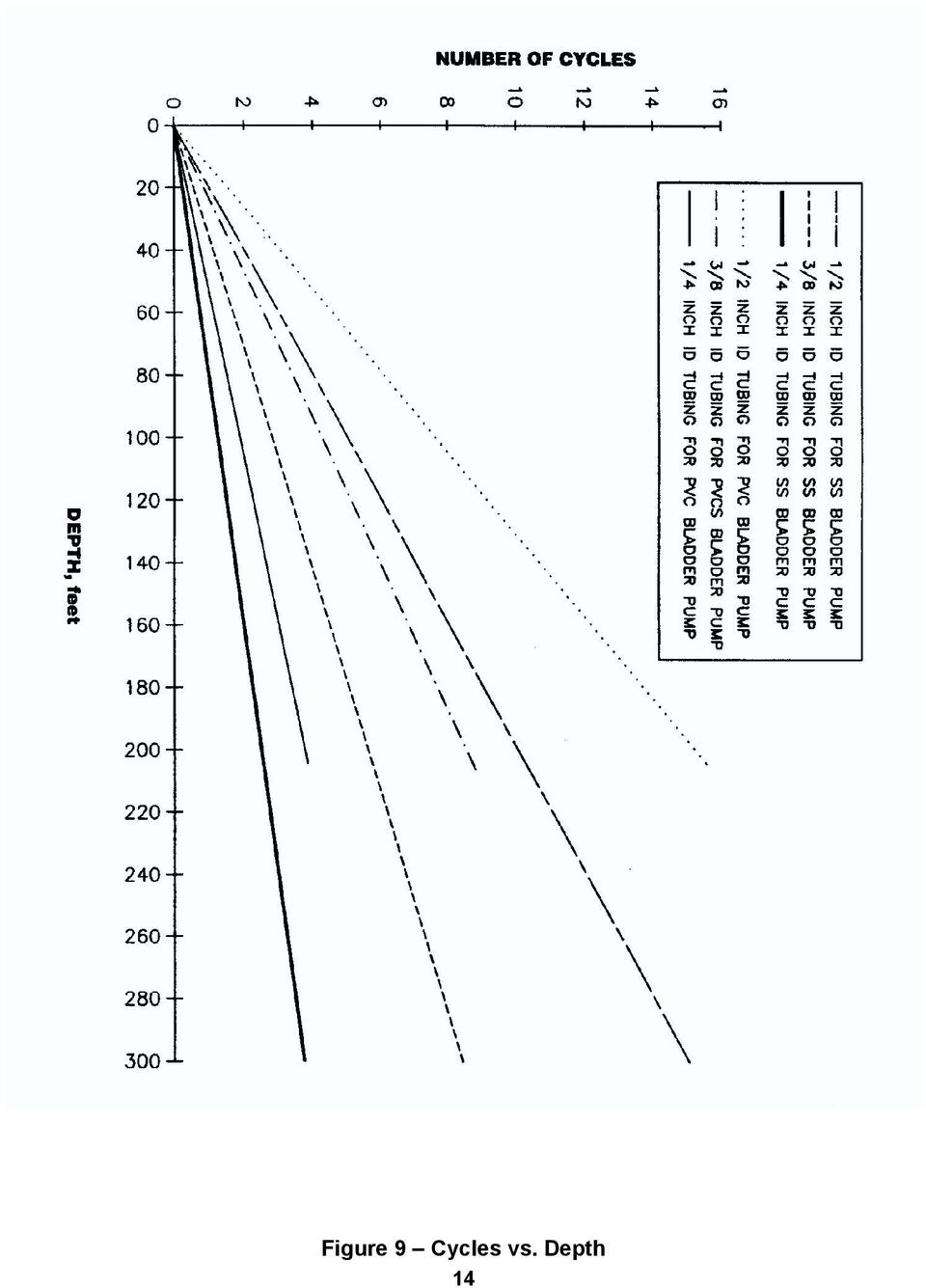
9 Chapter 3: System Operation Bladder Pump Operation Fluid enters the pump through the fluid inlet check valve at the bottom of the pump body, and the bladder fills with fluid. Compressed air enters the space between the bladder and the interior of the pump wall housing, the inlet check valve closes and the discharge check valve opens. The compressed air squeezes the bladder pushing the fluid to the surface. The discharge check valve prevents backflow from the discharge tubing. Selecting an Air Source The following explanation is based on the Model GEO1.66SS36 with a.170 ID air supply tubing. To determine the required capacity of the air source used, calculate the air consumption as follows. With 100 ft. of air line tubing in or out of the well, the air consumption is 125 cubic inches per cycle, with 6 cycles per minute (average). Example: For 100 ft. of tubing you will need 125 cu. in. x 6 per min. which equals 750 cu. in. / min. or 45,000 cu. in. / hr. For each additional 100 ft. add 59 cu. in. If you plan to use an air compressor we advise that you use one with a reserve tank to insure proper air supply to the pump. If you plan to use a Nitrogen Tank, see figure 9 for Nitrogen Tank Volume vs. Bladder Pump consumption. Determining PSI Determine the air pressure needed to operate the Bladder Pump based on the length of the air supply line to the pump (well depth). Use the simplified formula of (1/2 PSI per foot) + 10 PSI for friction. Example: For a pump 100 ft. away from the air source, uses 100 ft. divided by 2 then add 10. This equals 60 PSI (100' / = 60 PSI). The additional 10 PSI is to account for the pump itself and friction loss along the air line tubing. When the length of the air line to the Bladder Pump is 50 ft. or less, the additional 10 PSI need not be added. To determine minimum operating pressures for the specific Bladder Pump model you are using, consult pumps specifications. Typically the minimum operating pressure will be 5 PSI above static head. Example: Bladder Pump depth is 50 ft. 50 / 2 = = 30 PSI. 8

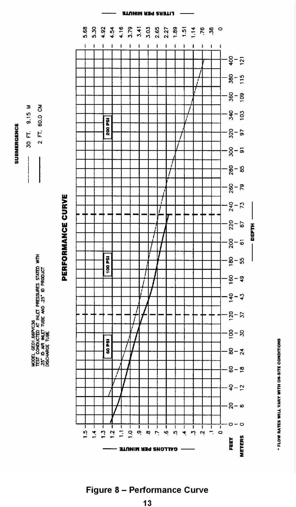
10 The formulas stated above are not absolute, and are meant to provide baseline information. Flowrates Flow rates are based on Geotech s models GEO1.66ss36 Stainless Steel Bladder Pump, and GEO1.66PVC36 PVC Bladder Pumps PERFORMANCE CURVE (see figures 5, 6, 7, & 8). For determining the number of cycles it will take to receive sample fluid at the well head, see figure 9 CYCLES vs. DEPTH. If using a nitrogen tank as an air source, see figure 10 NITROGEN TANK VOLUME vs. BLADDER PUMP CONSUMPTION. 9

11 Figure 5 Performance Curve 10

12 Figure 6 Performance Curve 11

13 Figure 7 Performance Curve 12

14 Figure 8 Performance Curve 13
15 Figure 9 Cycles vs. Depth 14
16 Figure 10 Nitrogen Tank vs. Bladder Pump Consumption 15

17 Chapter 4: System Maintenance Bladder Pump As with any pump, scheduled or periodic maintenance should be performed, according to your sampling program and specific site conditions. Generally, the more turbid or sandy your water, the more often you should maintain and clean your pumps. (See System components, Bladder Cartridge Assembly). Disassemble Bladder Pump per instructions, decontaminate or replace as needed, then reassemble. Inspect all check balls for wear and replace as necessary. Inspect all O-rings for splits or cracks and replace as necessary. Bladder Cartridge When installing a new bladder cartridge, or performing maintenance on an existing cartridge use the following instructions: Pull pump from the well, it is not necessary to remove the air and sample lines from the pump. (Models w/screens) Using an Allen head tool, remove the shoulder bolts from the intake screen cap (see figure 1). Using the Spanner tool, while holding pump body, with your hand or with a strap wrench, use a spanner tool to turn lower head in a counter clockwise direction and remove. Pump head will be very snug due to the high pressure O-ring seal. Once the seal is broken, the lower head will turn very easily (see figure 12). The internal bladder cartridge can now be removed for maintenance or replacement. Gently tap the tube housing on a firm wood like surface until the cartridge drops from the upper head seal. Reach into the tube with one or two fingers and pull the cartridge free. Before replacing lower pump head, always check o-rings for rips or cracks and replace as necessary. For models without intake screens, use the Spanner tool provided for lower head removal (see figure 12). 16

18 Figure 11 17

19 Chapter 5: System Troubleshooting Bladder Pump: Troubleshooting Problem: Solutions: Air is cycling thru controller, but will not pump 1) Charge and exhaust times are not set correctly. Check and adjust charge and exhaust cycle times (i.e. if charge time is too long or if exhaust and charge time is too short). 2) Possible compromise in air line tubing. Check air line pump for leaks. If needed, repair using compression union or replace tubing. 3) Check pump intake screen for blockage and clean as needed. Controller is cycling but the pump stops producing water 1) Check drawdown level of water in the well. Ensure the pump is fully submerged and off of the bottom of the well. 2) Check psi at the regulator and adjust as necessary (see page 8). 3) Check for kinks in the discharge line. 4) Check pump intake screen for obstructions. 5) Charge time is too long or exhaust time is too short; causes pressure build up in pump, causing the pump not to fill. 6) Check power source, assure a strong reliable power supply. If using and old or weak battery, the control valves may not operate properly. 18
 Check drawdown level of water in the well. Ensure the pump is fully submerged and off of the bottom of the well.")
20 System Troubleshooting cont... Getting air bubbles in sample line 1) Over charging pump. Reduce charge cycle time so that charge cycle ends as fluid discharge trails off. Inspect pump for compromised bladder or o- rings. 2) Pump is being over pressurized (PVC pump). Reduce psi to what is necessary to overcome pumping head (see page 8 for determining psi). 3) Check discharge line for holes or kinks. Repair using compression union or replace tubing. Discharge line drains back into pump 1) Remove Hosebarb on pump discharge outlet. Check the check ball seat for debris. Clean and re-install. 19
 Check discharge line for holes or kinks. Repair using compression union or replace tubing.")
21 Chapter 6: System Specifications GEO1.66SS36 GEO1.66SS18 GEO1.66PVC36 Pump Housing SS, 316 SS, 316 PVC Pump Ends Virgin PTFE Virgin PTFE PVC Bladder Matl. Virgin PTFE Proprietary resin Grade (G303) Virgin PTFE Proprietary resin grade (G303) Virgin PTFE (Proprietary resin grade G303) O.D.: 1.66 /4.2cm 1.66 /4.2cm 1.66 /4.2cm Length: w/o screen Length: w/screen 36 /91.4cm 18 /45.7cm 36 /91.4cm 38 /96.5cm 20 /51cm Weight 5lb/1.9Kg. 2.5lb/0.93Kg 3.6lb/1.3Kg Volume/Cycle 21.1oz./625ml 10.5oz./313ml 13.8oz.408ml Max. Flowrate* 1.25gpm/4.7lpm.65gpm/2.4lpm.97gpm/3.7lpm Min. Well I.D. 2 /50mm 2 /50mm 2 /50mm Operating Press psi/.7-31 bar psi/.7-31bar psi/ bar Min. Operating Range 5psi/.34bar above static head 5psi/.34bar above static head 5psi/.34bar above static head Maximum Depth ** 1000 /305m 1000 /305m 250 /76.2M * Flow rate 2ft/60cm submergence ** With the use of a drop tube, maximum depth is increased 20
22 System Specifications GEO1.66PVC18 GEO850.SS24 GEO675.SS18 Pump Housing PVC SS, 316 SS, 316 Pump Ends PVC Virgin PTFE Electropolished SS 316 Bladder Matl. Virgin PTFE (Proprietary resin grade G303) Virgin PTFE (Proprietary resin grade G303) Virgin PTFE (Proprietary resin grade G303) O.D.: 1.66 /4.2cm.850 /2.2cm.675 /1.7cm Length: w/o screen Length: w/screen 18 /45.7cm 24 /61cm N/A 22 /55.9cm 25 /63.5cm 18 Weight 1.8lb/.67Kg 1.6/.60Kg.83lb/.38Kg Volume/Cycle 6.9oz./204ml 2.1oz./59.6ml 1.35oz./38.4ml Max. Flowrate*.53gpm/2.0lpm.10gpm/.36lpm.05gpm/.19lpm Min. Well I.D. 2 /25mm 1.00 /25mm.75 /19mm Operating Press psi/.7-7.5bar psi/.7-7.5bar psi/.7-7.5bar Min. Operating Range 5psi/.34bar above static head 5psi/.34bar above static head 5psi/.34bar above static head Maximum Depth ** 250 /76.2m 250 /76.2m 250 /76.2m 21
23 Chapter 7: System Schematic GEO1.66SS36 GEO1.66SS18 GEO1.66PVC36 22
24 GEO1.66PVC18 GEO850.SS24 GEO675.SS18 23
25 Chapter 8: Replacement Parts List Model GEO1.66SS36 QTY/ASSY DESCRIPTION PART # 1 Bladder Cartridge Cap, Upper Cap, Lower Screen, Intake Bolts, Shoulder Hose barb, Sample out Hose barb, Air in Check ball, Upper Check ball, Lower O-Ring Viton cap/upper lower O-Ring Viton cap/upper head interface O-Ring Viton cap/lower head interface MODEL GEO1.66SS18 QTY/ASSY DESCRIPTION PART # 1 Bladder Cartridge Cap, Upper Cap, Lower Screen, Intake Bolts, Shoulder Hose barb, Sample out Hose barb, Air in Check ball Upper Check ball Lower O-Ring Viton cap/upper lower O-Ring Viton cap/upper head interface O-Ring Viton cap/lower head interface
26 Model GEO1.66PVC36 QTY/ASSY DESCRIPTION PART # 1 Bladder Cartridge Cap, Upper Cap, Lower Screen, Intake Cap Screen Intake Hose barb, Sample out Hose barb, Air in Check ball, PVC Upper/lower O-Ring, Viton cap/upper/lower O-Ring Viton cap/head interface MODEL GEO1.66PVC18 QTY/ASSY DESCRIPTION PART # 1 Bladder Cartridge Cap, Upper Cap, Lower Screen, Intake Cap, screen intake Hose barb, Sample out Hose barb, Air in Check, PVC Upper/lower O-Ring Viton cap/upper lower O-Ring Viton cap/head interface
27 Model GEO850.SS24 QTY/ASSY DESCRIPTION PART # 1 Bladder Cartridge Cap, Upper Cap, Lower Screen, Intake Screw 4-40 x Hose barb, Sample out Hose barb, Air in Check ball O-Ring, Viton cap/upper/lower O-Ring Viton cap/upper head interface O-Ring Viton cap/lower head interface MODEL GEO.675SS18 QTY/ASSY DESCRIPTION PART # 1 Bladder Cartridge Cap, Upper Cap, Lower Hose barb, air sample Check ball, upper ppm Check ball, lower Disc Teflon Snapring O-Ring, Bladder Cap, Upper O-Ring, Bladder Cap, Lower O-Ring, cap housing
28 Notes 27
29 The Warranty For a period of one (1) year from date of first sale, product is warranted to be free from defects in materials and workmanship. Geotech agrees to repair or replace, at Geotech s option, the portion proving defective, or at our option to refund the purchase price thereof. Geotech will have no warranty obligation if the product is subjected to abuse, misuse, or inability to use this product. User assumes all other risk, if any, including the risk of injury, loss, or damage, direct or consequential, arising out of the use, misuse, or inability to use this product. User agrees to use, maintain and install product in accordance with recommendations and instructions. User is responsible for transportation charges connected to the repair or replacement of product under this warranty. Equipment Return Policy A Return Material Authorization number (RMA #) is required prior to return of any equipment to our facilities, please call 800 number for appropriate location. An RMA # will be issued upon receipt of your request to return equipment, which should include reasons for the return. Your return shipment to us must have this RMA # clearly marked on the outside of the package. Proof of date of purchase is required for processing of all warranty requests. This policy applies to both equipment sales and repair orders. FOR A RETURN MATERIAL AUTHORIZATION, PLEASE CALL OUR SERVICE DEPARTMENT AT OR Model Number: Serial Number: Date: Equipment Decontamination Prior to return, all equipment must be thoroughly cleaned and decontaminated. Please make note on RMA form, the use of equipment, contaminants equipment was exposed to, and decontamination solutions/methods used. Geotech reserves the right to refuse any equipment not properly decontaminated. Geotech may also choose to decontaminate equipment for a fee, which will be applied to the repair order invoice. 28
30 Geotech Environmental Equipment, Inc 8035 East 40 th Avenue Denver, Colorado (303) (800) FAX (303) website:
Geocontrol PRO INSTALLATION AND OPERATION MANUAL. Rev. 1 03/18/04 Part # 11150263
 Geocontrol PRO INSTALLATION AND OPERATION MANUAL Rev. 1 03/18/04 Part # 11150263 TABLE OF CONTENTS Chapter 1: System Description... p. 05 Function and Theory...p. 05 Chapter 2: System Installation... p.
Signal Manager Installation and Operation Manual
 Signal Manager Installation and Operation Manual Rev.11/28/2008 Part # 26550007 Table of Contents CHAPTER 1: SYSTEM DESCRIPTION... 3 FUNCTION AND THEORY... 3 CHAPTER 2: SYSTEM INSTALLATION... 4 HARDWARE
Failure to comply with the following cautions and warnings could cause equipment damage and personal injury.
 1.0 IMPORTANT RECEIVING INSTRUCTIONS Visually inspect all components for shipping damage. Shipping Damage is not covered by warranty. If shipping damage is found, notify carrier at once. The carrier is
Installation and Operating Instructions Installation Instructions for SS EPE-316L Series
 INSTR3010 0406 Installation and Operating Instructions Installation Instructions for SS EPE-316L Series Congratulations on your purchase of this Aqua-Pure high flow, single housing filtration system. This
Overview PARTS LIST. B. Lever mounting base C. Flush handle assembly D. Grey/Blue float stop E. Grey float (Full Flush) F. Flush valve washer
 F. Flush valve washer") Overview READ ENTIRE INSTRUCTIONS BEFORE STARTING INSTALLATION PARTS LIST A. Flush valve B. Lever mounting base C. Flush handle assembly D. Grey/Blue float stop E. Grey float (Full Flush) F. Flush valve
Overview READ ENTIRE INSTRUCTIONS BEFORE STARTING INSTALLATION PARTS LIST A. Flush valve B. Lever mounting base C. Flush handle assembly D. Grey/Blue float stop E. Grey float (Full Flush) F. Flush valve
MODEL G300 BRAKE BLEEDER
 MODEL G300 BRAKE BLEEDER Installation, Operation & Repair Parts Information Branick Industries, Inc. 4245 Main Avenue P.O. Box 1937 Fargo, North Dakota 58103 REV060616 P/N: 81-0035G 1 THIS PAGE INTENTIONALLY
Failure to comply with the following cautions and warnings could cause equipment damage and personal injury.
 1.0 IMPORTANT RECEIVING INSTRUCTIONS Visually inspect all components for shipping damage. Shipping Damage is not covered by warranty. If shipping damage is found, notify carrier at once. The carrier is
FLUSHOMETER - TANK SYSTEM
 Owner s Service Manual 501-A Series FLUSHOMETER - TANK SYSTEM 501-A Series FLUSHMATE 501-A SERIES (D) (E) (C) 2 3 (B) 1 4 (F) (A) 6 5 List of Components for 501-A Series*: 1. Lower Supply Group w/hose
Tech. Services: (800) 477-8326 Fax: (800) 765-8326 Order Entry: (800) 541-1418 Fax: (800) 288-7031 Internet Address: http://www.powerteam.
 477-8326 Fax: (800) 765-8326 Order Entry: (800) 541-1418 Fax: (800) 288-7031 Internet Address: http://www.powerteam.") ORIGINAL INSTRUCTIONS Form No.102842 5 SPX Hydraulic Technologies 5885 11th Street Rockford, IL 61109-3699 USA Tech. Services: (800) 477-8326 Fax: (800) 765-8326 Order Entry: (800) 541-1418 Fax: (800)
ORIGINAL INSTRUCTIONS Form No.102842 5 SPX Hydraulic Technologies 5885 11th Street Rockford, IL 61109-3699 USA Tech. Services: (800) 477-8326 Fax: (800) 765-8326 Order Entry: (800) 541-1418 Fax: (800)
Stainless Steel Valves For the Sanitary Industries
 www.swagelok.com Stainless Steel Valves For the Sanitary Industries Sanitary ball valves Manual and pneumatically actuated butterfly valves Disk and ball check valves ir blow check valves ir relief valves
DeZURIK 3-20" BAW AWWA BUTTERFLY VALVES WITH TRANSFER MOLDED SEAT
 3-20" BAW AWWA BUTTERFLY VALVES WITH TRANSFER MOLDED SEAT Instruction D10386 August 2013 Instructions These instructions provide installation, operation and maintenance information for BAW Butterfly Valves.
MAINTENANCE MANUAL INDEX DOUBLE CHECK ASSEMBLIES MODELS 850 & 850U 1/2" - 2"
 MAINTENANCE MANUAL INDEX DOUBLE CHECK ASSEMBLIES MODELS 850 & 850U 1/2" - 2" FEATURES AND OPERATING PROCEDURES VANDALISM GENERAL SERVICE PROCEDURES CUT-A-WAY DRAWING TROUBLE SHOOTING PROCEDURES CHECK MODULE
Important: Please read these instructions carefully and completely before starting the installation. TITAN Fuel Tanks
 TITAN pt. no.: 03 0000 0120 Important: Please read these instructions carefully and completely before starting the installation. TITAN Fuel Tanks INSTALLATION INSTRUCTIONS G e n e r a t i o n V Extended
PNEUMATIC PLANISHING HAMMER
 PNEUMATIC PLANISHING HAMMER 94847 ASSEMBLY AND OPERATING INSTRUCTIONS Due to continuing improvements, actual product may differ slightly from the product described herein. Distributed Exclusively by Harbor
PALLET JACK - 2.5 TON
 PALLET JACK - 2.5 TON 39939 SET UP AND OPERATING INSTRUCTIONS Visit our website at: http://www.harborfreight.com Read this material before using this product. Failure to do so can result in serious injury.
INSPECTION, MAINTENANCE AND RECHARGE SERVICE MANUAL P/N 16303
 WATER MIST HAND PORTABLE FIRE EXTINGUISHERS Model B270 ¾ Gallon Model B272 2 ½ Gallon INSPECTION, MAINTENANCE AND RECHARGE SERVICE MANUAL P/N 6303 All fire extinguishers should be installed, inspected
Operator s Manual. Pressure Injection Cell Model PC8500. Congratulations! Contents
 Operator s Manual Pressure Injection Cell Model PC8500 Congratulations! Congratulations on your purchase of a Next Advance Pressure Injection Cell. Please read this operator s manual which explains proper
System Saver 318 Air Compressor for Mack E-Tech and ASET Engines
 Maintenance Manual 31 System Saver 318 Air Compressor for Mack E-Tech and ASET Engines Revised 08-05 NON-THROUGH DRIVE THROUGH DRIVE Service Notes About This Manual This manual provides service and repair
DANGER DANGER. General Information. Safety Is Your Responsibility. Ordering Parts. Contact Information
 Safety Safety Is Your Responsibility DANGER To avoid personal injury or death, carefully read and understand all instructions pertaining to the Anthony Liftgates product. Do not attempt to install, operate,
HPU14M-DS 2013 Daniels Manufacturing Corp., All Rights Reserved Page 1 of 17 REV. C 7/2013
 The DMC HPU14M is a robust, 110V electrically powered hydraulic pump, designed to provide a hydraulic system pressure of 10,000psi. This pump can be used with compatible heads and hoses, designed for a
Dive Rite 200 & 300 Bar Isolator Manifold Service Manual
 Dive Rite 200 & 300 Bar Isolator Manifold Service Manual Principal Photography and Text by Pete Nawrocky Copyright 2003 Lamartek Inc. D/B/A Dive Rite 0 Warning This manual is only to be used as a guide
el-720 Carbon Dioxide Gas Leak Detector User s Guide
 el-720 Carbon Dioxide Gas Leak Detector User s Guide Congratulations on the purchase of the AccuTools el-720 Carbon Dioxide Gas Leak Detector, the most technologically advanced instrument of its kind.
BACKPACK SPRAYERS. MODEL NOS: KSP16 & KSP20 Part Nos: 3402270 & 3402275 OPERATING & MAINTENANCE INSTRUCTIONS GC04/12
 BACKPACK SPRAYERS MODEL NOS: KSP16 & KSP20 Part Nos: 3402270 & 3402275 OPERATING & MAINTENANCE INSTRUCTIONS GC04/12 INTRODUCTION Thank you for purchasing this CLARKE Sprayer, designed for use only with
Installation Instructions 4508 4508S
 SYMPHONY Spread Lavatory Faucet with Speed Connect Drain Congratulations on purchasing your American Standard faucet with Speed Connect drain, a feature found only on American Standard faucets. Speed Connect
OPERATING MANUAL CONTRACTOR STYLE AXIAL FANS
 Manual No. BLWR043 Rev. 4 September 2012 OPERATING MANUAL CONTRACTOR STYLE AXIAL FANS CVF-8AC CVF-8AC50 CVF-6ACAN CVF-15ACAN CVF-25ACAN CVF-8A15KIT CVF-8A25KIT MODELS: CVF-8DC CVF-6DCAN CVF-15DCAN CVF-25DCAN
STORED PRESSURE STAINLESS STEEL
 STORED PRESSURE STAINLESS STEEL WATER FIRE EXTINGUISHERS Model 240-2-1/2 Gallon OWNER'S SERVICE MANUAL NO. 05601 INSPECTION, MAINTENANCE AND RECHARGE All fire extinguishers should be installed, inspected
product manual 08.09 H-4210A PORTABLE STATIC CONE PENETROMETER
 08.09 product manual H-4210A PORTABLE STATIC CONE PENETROMETER PORTABLE STATIC CONE PENETROMETER GENERAL INFORMATION The H-4210A Static Cone Penetrometer is an unparalleled device for measuring soil consistency.
BUILT-IN DISHWASHER INSTALLATION INSTRUCTIONS
 BUILT-IN DISHWASHER INSTALLATION INSTRUCTIONS PLEASE READ COMPLETE INSTRUCTIONS BEFORE YOU BEGIN LEAVE INSTALLATION INSTRUCTIONS AND USER'S GUIDE WITH OWNER ALL ELECTRIC WIRING AND PLUMBING MUST BE DONE
- Do not immerse cords, pump or any electrical wire or device in water or other liquid.
 TRANSFER PUMP INSTRUCTIONS FOR THE SUPER TRANSFER PUMP 1. Pump (water may be present in the pump and lines due to testing at factory) 2. Instructions. 3. Inlet thicker wall hose (1), outlet hose (1) 4.
TITAN Fuel Tanks. INSTALLATION INSTRUCTIONS G e n e r a t i o n V
 TITAN pt. no.: 02 0000 0143 Important: Please read these instructions carefully and completely before starting the installation. TITAN Fuel Tanks INSTALLATION INSTRUCTIONS G e n e r a t i o n V Extended
USE &CARE GUIDE. Remote Faucet Pump System. See Important Safeguards on page 2
 Remote Faucet Pump System USE &CARE GUIDE See Important Safeguards on page 2 An exclamation point within an equilateral triangle is intended to alert user to the presence of important operating and maintenance
Failure to comply with the following cautions and warnings could cause equipment damage and personal injury.
 1.0 IMPPORTANT RECEIVING INSTRUCTIONS Visually inspect all components for shipping damage. Shipping Damage is not covered by warranty. If shipping damage is found, notify carrier at once. The carrier is
TECHNICAL ASSISTANCE TOLL FREE TELEPHONE NUMBER 1.800.591.9360 TECHNICAL ASSISTANCE FAX: 1.626.855.4894
 ACORN SAFETY P.O. BOX 3527 CITY OF INDUSTRY, CA 9744-0527 UNITED STATES OF AMERICA WWW.ACORNSAFETY.COM INSTALLATION, OPERATION AND MAINTENANCE INSTRUCTIONS FREEZE RESISTANT WALL MOUNTED EMERGENCY EYEWASH
BOWIE PUMPS OPERATION - MAINTENANCE
 BOWIE PUMPS OPERATION - MAINTENANCE PUMPING PRINCIPLE: The meshing owieeof the gears cause a slight depression, with the resulting enmeshing of the gears causing a vacuum drawing the fluid being pumped
FLUSHMATE FLUSHMATE FLUSHOMETER - TANK SYSTEM. Owner s Service Manual 503 and 504 Series
 Owner s Service Manual 503 and 504 Series FLUSHMATE FLUSHOMETER - TANK SYSTEM 503 504 FLUSHMATE A Division of Sloan Valve Company 30075 Research Drive New Hudson, MI 48165 800-533-3460 248-446-5300 http://www.flushmate.com
http://waterheatertimer.org/troubleshoot-rheem-tankless-water-heater.html
 http://waterheatertimer.org/troubleshoot-rheem-tankless-water-heater.html TECHNICAL SERVICE DEPARTMENT Removal, Cleaning, & Reinstallation of the Burner Assembly For models 74 & GT199 Required tools -
3M Water Filtration Products. CFS01 Series, CFS02 Series, CFS11 Series, and CFS12 Series Housings. Installation and Instruction Manual For:
 3M Water Filtration Products Installation and Instruction Manual For: CFS01 Series, CFS02 Series, CFS11 Series, and CFS12 Series Housings Installer: Please leave this manual with owner/operator. Owner/Operator:
Tipping Bucket Rain Gauge Models 6011-A 6011-B
 Tipping Bucket Rain Gauge Models 6011-A 6011-B User s Manual 1165 National Drive Sacramento, CA 95834 800.824.5873 Table of Contents General Information... 1 Introduction... 1 Installation General... 2
OP300S / OP350 2:1 RATIO TRANSFER PUMP
 OP300S / OP350 2:1 RATIO TRANSFER PUMP OPERATING MANUAL WITH PARTS IDENTIFICATION Copyright 2013 International Pump Manufacturing, Inc. This manual contains IMPORTANT WARNINGS and INSTRUCTIONS. Read and
CLEAN AND CLEAR PLUS CARTRIDGE FILTER
 CLEAN AND CLEAR PLUS CARTRIDGE FILTER INSTALLATION AND USER S GUIDE IMPORTANT SAFETY INSTRUCTIONS READ AND FOLLOW ALL INSTRUCTIONS SAVE THESE INSTRUCTIONS i CUSTOMER SERVICE / TECHNICAL SUPPORT If you
This kit may void factory warranty please check with manufacturer.
 Thank you for purchasing a Sinister Manufacturing Company EGR delete kit. Precision manufactured using the highest grade 304 stainless steel and 6061 billet aluminum; this EGR kit is designed to endure
Hydraulic Transmission Jacks Operating Instructions & Parts Manual
 Blackhawk Automotive is a Licensed Trade Mark Made by SFA Companies, Kansas City, MO Hydraulic Transmission Jacks Operating Instructions & Parts Manual Model BH7011 BH7210 Capacity 1/2 Ton 1 Ton SFA Companies
ENGINE FUEL FUEL FILTER... FUEL HEATER... INJECTOR... SUPPLY PUMP... COMMON RAIL... FUEL PRESSURE LIMITTER...
 FUEL FILTER............................ FUEL HEATER.......................... INJECTOR.............................. SUPPLY PUMP.......................... COMMON RAIL.......................... FUEL PRESSURE
SE-100-1, SE-200-1, SE-500-1, and SE-1000-1 AIR CHAMP PRODUCTS. User Manual SE BRAKE MODELS: (i) MTY (81) 83 54 10 18 ventas@industrialmagza.
 MTY (81) 83 54 10 18 ventas@industrialmagza.") AIR CHAMP PRODUCTS User Manual SE BRAKE MODELS: SE-00-, SE-200-, SE-500-, and SE-000- (i) FORM NO. L-20084-E-040 In accordance with Nexen s established policy of constant product improvement, the specifications
AIR CHAMP PRODUCTS User Manual SE BRAKE MODELS: SE-00-, SE-200-, SE-500-, and SE-000- (i) FORM NO. L-20084-E-040 In accordance with Nexen s established policy of constant product improvement, the specifications
300 SERIES 331, 332, 333, 344, 356 AND 367 MODELS
 Section: MOYNO 500 PUMPS Page: 1 of 8 Date: March 1, 1998 SERVICE MANUAL MOYNO 500 PUMPS 300 SERIES 331, 332, 333, 344, 356 AND 367 MODELS Mechanical Seal Models Packing Gland Models MODELS DESIGN FEATURES
Stainless Steel Single and Dual Circulation Kits
 Instruction Sheet P/N 160780 01 Stainless Steel Single and Dual Circulation Kits Introduction The single and dual high-pressure circulation kits allow you to vary and control the circulation rate of coating
STATFlow. Direct-to-Drain System. For use with STATIM 2000 and STATIM 5000 Autoclaves. Installation Guide and Operator s Manual
 STATFlow Direct-to-Drain System For use with STATIM 2000 and STATIM 5000 Autoclaves Installation Guide and Operator s Manual STATFlow Installation Guide and Operator s Manual 95-113193 Rev 2.0. Copyright
Float and Thermostatic Traps Series H, C and X
 Hoffman Specialty Installation & Maintenance Instructions HS-(E) and Thermostatic Traps Series H, C and X Series C & NPT Series C NPT Series X NPT Series C NPT Series H Ratings Maximum Max. Operating NPT
Line to Refrigerator Ice/Water Dispenser
 Standard 18 Line to Refrigerator Ice/Water Dispenser Pump Module Bottled Water How The System Works The FLOJET Bottled Water Dispensing System was designed to pump water from a commercially available 5-gallon
Installation, Maintenance, & Repair Series 4000B/LF4000B
 Installation, Maintenance, & Repair Series 4000B/LF4000B Reduced Pressure Zone Assemblies Sizes: 1 2" 2" (15 50mm) RP/IS-A-4000B 4000B/LF4000B Size: 3 /4"! WARNING Testing Read this Manual BEFORE using
Instruction Manual. Alfa Laval SB Membrane Sample Valve ESE02963-EN1 2015-10. www.sks-online.com www.sks-webshop.com.
 Instruction Manual Alfa Laval SB Membrane Sample Valve ESE02963-EN1 2015-10 Original manual Table of contents The information herein is correct at the time of issue but may be subject to change without
2006 HEADSHOK Service Video #1
 LEFTY SPEED DLR DAMPING CARTRIDGE This document explains how to properly remove, disassemble, inspect, reassemble and reinstall the Lefty Speed DLR2 damping cartridge. It is a document to be used in conjunction
FJ2. 2 Ton Trolley Floor Jack Assembly & Operating Instructions
 FJ2 2 Ton Trolley Floor Jack Assembly & Operating Instructions READ ALL INSTRUCTIONS AND WARNINGS BEFORE USING THIS PRODUCT. This manual provides important information on proper operation & maintenance.
8 ton air/hydraulic long ram jack
 8 ton air/hydraulic long ram jack Model 94562 Set up and Operating Instructions Visit our website at: http://www.harborfreight.com Read this material before using this product. Failure to do so can result
OPERATING INSTRUCTION MANUAL FOR S-240 HYDRAULIC CUTTERS WITH PARTS LIST
 HUSKIE TOOLS, INC. OPERATING INSTRUCTION MANUAL FOR S-240 HYDRAULIC CUTTERS WITH PARTS LIST GENERAL INFORMATION GUIDE FOR S-240 CUTTER The following steps are guidelines for safe operation of the Huskie
tire inflator with pressure gauge
 tire inflator with pressure gauge Model 95583 Assembly And Operation Instructions Due to continuing improvements, actual product may differ slightly from the product described herein. 3491 Mission Oaks
Operating Instruction Manual For S-40B Hydraulic Cutters With Parts List
 HUSKIE TOOLS, INC. Operating Instruction Manual For S-40B Hydraulic Cutters With Parts List GENERAL INFORMATION GUIDE FOR S-40B CUTTER The following steps are guidelines for safe operation of the Huskie
Before repairing your toilet, you must determine
 Before repairing your toilet, you must determine which type of toilet you have. Pressurized Toilets If you have a pressurized toilet, it is recommended that you call a licensed plumbing contractor to repair
Tri-Homo Style Operation and Maintenance Instructions
 Tri-Homo Style Operation and Maintenance Instructions One Research Drive Stratford, CT 06615 (203) 375-0063 www.sonicmixing.com 1 Installation and Start-up Do not perform following adjustments without
SDX Submersible Depth Transmitter User Manual
 SDX Submersible Depth Transmitter User Manual January 2011 USER INFORMATION Stevens makes no warranty as to the information furnished in these instructions and the reader assumes all risk in the use thereof.
Submersion/Insertion Toroidal Sensor
 Instruction Sheet PN 51A-228/rev.P December 2010 Model 228 Submersion/Insertion Toroidal Sensor For additional information, please visit our website at www.emersonprocess.com/raihome/liquid/. CAUTION SENSOR/PROCESS
TABLE OF CONTENTS. SECTION 1 General Information: Pg 2 Description of Operation
 GTRDD SERIES HEATLESS DRYER INSTALLATION, OPERATION & MAINTENANCE MANUAL TABLE OF CONTENTS SECTION 1 General Information: Pg 2 Description of Operation SECTION 2 Safety Instructions: Pg 3 Installation
SERVICE PARTS INSTRUCTIONS
 WACO MERITOR SERVICE PARTS INSTRUCTIONS Installing the Meritor WABCO System Saver 1000 and 1200 Series Air Dryers For Use on Tractors, Trucks and Buses with Air Brakes Installation Requirements 5 P/N 434
Cleaning Instructions, Pilot Replacement and Valve Change. Model No.: 233010 Natural Gas
 Cleaning Instructions, Pilot Replacement and Valve Change Model No.: 233010 Natural Gas 8mm open-end wrench 9mm open-end wrench 10mm open-end wrench 12mm open-end wrench 13mm open-end wrench Phillips screw
Oil and Coolant Circulating Heating System. Model - OCSM
 Oil and Coolant Circulating Heating System Model - OCSM Installation & Operation Manual 216280-000 REV 2 Identifying Your System The HOTSTART heating system is designed to heat fluids for use in marine
IMPORTANT DOCUMENTATION DO NOT DISCARD!
 PART NO.: 6441-263C SERIES GRT 3 JAW PARALLEL GRIPPERS INFORMATION SHEET IMPORTANT DOCUMENTATION DO NOT DISCARD! Use this information sheet to assist with gripper installation and setup. File with maintenance
Extrusion Flo-Valve INSTRUCTIONS-PARTS LIST. 3000 psi (210 bar) Maximum Working Pressure. Model 204 355, Series K. Rev.
 Maximum Working Pressure. Model 204 355, Series K. Rev.") INSTRUCTIONS-PARTS LIST INSTRUCTIONS This manual contains important warnings and information. READ AND KEEP FOR REFERENCE. 306 586 Rev. D Supercedes B Extrusion Flo-Valve Model 204 355, Series K 3000 psi
INSTRUCTIONS-PARTS LIST INSTRUCTIONS This manual contains important warnings and information. READ AND KEEP FOR REFERENCE. 306 586 Rev. D Supercedes B Extrusion Flo-Valve Model 204 355, Series K 3000 psi
Fiberstars Mini Lighted Laminar Flow Fountains
 Fiberstars Mini Lighted Laminar Flow Fountains SAVE THESE DIRECTIONS! These directions are provided to ensure the proper installation and operation of Fiberstars Mini Lighted Laminar Flow Fountain. The
Assembly and instructions
 Assembly and instructions Franke Minerva 3-in-1 Kettle Tap Retain for reference NB: For use only with Franke Heating Tank INTRODUCTION The Kettle Tap is suitable for dispensing boiling water (100 C) and
Round Housing with Side Ports
 Power Steering Steering Control Unit (SCU) Parts and Repair Information 5 Series Steering Control Units 001 Square Housing with Side Ports Round Housing with Side Ports T E L RP Round Housing with End
81000 Series Aluminum Gate Valve Installation and Repair Manual
 High Vacuum Valves Leader in Quality and Value 81000 Series Aluminum Gate Valve Installation and Repair Manual Dear Customer, Thank you for choosing HVA as your vacuum valve supplier. Your valve will give
REPAIR AND MAINTENANCE MANUAL
 REPAIR AND MAINTENANCE MANUAL Professional Pest Control Application Equipment Prime Line Sprayers B&G Equipment Company 135 Region South Drive, Jackson, GA 30233 800.544.8811 Phone 678.688.5601 Fax 678.688.5633
Back Pack Sprayer. Operator's Manual MODELS MS - 40 MS - 50
 Back Pack Sprayer Operator's Manual MODELS MS - 40 MS - 50 WARNING DANGER Read rules for safe operation and all instructions carefully. ECHO provides this Operator's Manual which must be read and understood
INSTALLATION & OPERATING INSTRUCTIONS
 INSTALLATION & OPERATING INSTRUCTIONS WARNING RISK OF ELECTRIC SHOCK. CONNECT ONLY TO A CIRCUIT PROTECTED BY A GROUND-FAULT CIRCUIT-INTERRUPTER. THE UNIT SHOULD BE INSTALLED BY A QUALIFIED SERVICE REPRESENTATIVE.
ClearView 100. Instruction Manual
 ClearView 100 Instruction Manual Important Safeguards This appliance is not intended for use by children or infirm persons without supervision. Young children should be supervised to ensure that they do
DTM04 TANK MONITOR DTM08 TANK MONITOR Dtm12 TANK MONITOR. Installation and Operation Manual
 DTM04 TANK MONITOR DTM08 TANK MONITOR Dtm12 TANK MONITOR Installation and Operation Manual 1 ENGLISH Safety Instructions 2 Features 2-3 Specifications 3 Installation 4-5 Wiring Diagrams 6-7 Warranty 8
TECHNICAL BULLETIN. Meritor WABCO Cab Leveling Valves and Chassis Leveling Valves. How the Cab Leveling and Chassis Leveling Valves Work
 Revised 02-00 TECHNICAL BULLETIN Meritor WABCO Cab Leveling Valves and Chassis Leveling Valves This technical bulletin covers both cab and chassis leveling valves manufactured by Meritor WABCO. While the
Global Water Instrumentation, Inc.
 Global Water Instrumentation, Inc. 11390 Amalgam Way Gold River, CA 95670 T: 800-876-1172 Int l: (916) 638-3429, F: (916) 638-3270 Water Level Sensor: WL400 00-997 11/30/09-1 - Congratulations on your
MAC FAUCETS. Owner s Manual. Models: FA444
 MAC FAUCETS Owner s Manual Models: FA444 Installation procedure: 1. Take a moment to view drawings and read special Installation note on page 3 of this manual before proceeding with installation. Connect
Installation and Troubleshooting Instructions for Electric Tankless Residential Water Heaters.
 Model Number: Serial Number: Information Manual Installation and Troubleshooting Instructions for Electric Tankless Residential Water Heaters. ATTENTION: IF YOU ARE NOT A LICENSED PLUMBER OR A LICENSED
Hydraulic Air Riveter. Operation Manual RC197 RC198. Recommend for mass production line industrial area. Page 1
 Hydraulic Air Riveter Recommend for mass production line industrial area Operation Manual RC197 RC198 Page 1 CONTENTS 1 Important Safety Rules 2 Tool Specification 2.1 Nomenclature 2.2 Technical Data 3
SHOT BLAST CABINET MODEL NO: CSB20B
 SHOT BLAST CABINET MODEL NO: CSB20B PART NO: 7640110 USER INSTRUCTIONS GC0216 INTRODUCTION Thank you for purchasing this CLARKE Shot Blast Cabinet which is designed for professional workshop use. Before
123 Industrial Loop Road Paynesville, MN 56362 Phone: 1-800-864-1649 www.master-mfg.com MASTER MANUFACTURING MASTER GARDNER
 123 Industrial Loop Road Paynesville, MN 56362 Phone: 1-800-864-1649 www.master-mfg.com MASTER MANUFACTURING MASTER GARDNER Part Number PCD E3 009B MM Rev 1 Nov. 2010 INTRODUCTION The purpose of this manual
Watts Pure Water Systems
 Watts Pure Water Systems WM-120-PT Installation and Operation Manual Premier Water Systems Do not use with water that is microbiologically unsafe or of unknown quality without adequate disinfection before
FOAM CHAMBER MODEL - FC
 FOAM CHAMBER MODEL - FC TECHNICAL DATA : MODEL SIZE WORKING PRESSURE FC 50, 65, 80, 100 &150 NB inlet Minimum 2.8 Kg. / sq. cm. (40 PSI) Maximum 7 Kg. / sq.cm. (100 PSI) FLANGE CONNECTION ANSI B16.5 Class
Compressor Service & Maintenance Manual
 Compressor Service & Maintenance Manual C Series COMPRESSOR (D)C1103 (D)C1203 (D)C2106 (D)C2206 (D)C3210 Copyright 2006 DCI. All Rights Reserved. 92311, Rev. C, 08/13 1 C1000 Series Service & Maintenance
GATE VALVES ASAHI AV VALVES. Type P (Standard: Plug) Type S (Soft Seal) Contents. (1) Be sure to read the following warranty clauses of our product 1
 Type S (Soft Seal) Contents. (1) Be sure to read the following warranty clauses of our product 1") Serial No. H-V011-E-11 GATE VALVES Type P (Standard: Plug) Type S (Soft Seal) Contents (1) Be sure to read the following warranty clauses of our product 1 User s Manual (2) General operating instructions
Serial No. H-V011-E-11 GATE VALVES Type P (Standard: Plug) Type S (Soft Seal) Contents (1) Be sure to read the following warranty clauses of our product 1 User s Manual (2) General operating instructions
SureSite Magnetic Liquid Level Indicator
 SureSite Magnetic Liquid Level Indicator Instruction Bulletin No. 177664-1 (Rev. E) Section 1: Weldments Thank you for purchasing the GEMS SureSite Magnetic Level Indicator. Please read this document prior
Auxiliary Rams USERS MANUAL
 Auxiliary Rams 2007 Chief Automotive Technologies, Inc. Chief s Limited One-Year Warranty & Liability CHIEF'S LIMITED ONE-YEAR WARRANTY & LIABILITY Chief Automotive Technologies, Inc. warrants for one
TITAN 13 x 2 ½ BRAKES
 INSTALLATION INSTRUCTION AND SERVICE MANUAL Actuator/Trailer Dealer - Please provide these instructions to the consumer. Consumer - Read and follow these instructions. Keep them with the trailer for future
INSTRUCTION MANUAL IM042. Slide Rail Systems - Series A10 INSTALLATION, OPERATION AND MAINTENANCE INSTRUCTIONS
 INSTRUCTION MANUAL IM042 Slide Rail Systems - Series A10 INSTALLATION, OPERATION AND MAINTENANCE INSTRUCTIONS TABLE OF CONTENTS SUBJECT PAGE Safety Instructions... 3 Descriptions and Specifications...
ROUGHNECK II Pumpless Drain
 SERVICE BULLETIN SB4027 Rev. I 1/11 For Used Oil Only ROUGHNECK II Pumpless Drain Model #4110-022 FOR USED OIL ONLY (Black) For Antifreeze Only Model #4110-023 FOR USED ANTIFREEZE ONLY (Green) Patent #
Name of Equipment Silver King Model SKMCD1P/C1. This equipment chapter is to be inserted in the appropriate section of the Equipment Manual.
 Name of Equipment Silver King Model SKMCD1P/C1 This equipment chapter is to be inserted in the appropriate section of the Equipment Manual. Manufactured exclusively for McDonald s By Silver King Refrigeration,
Installation Instructions 6028.801
 DAZZLE Installation Instructions 08.80 Spread Lavatory Faucet with Speed Connect Drain* Congratulations on purchasing your American Standard faucet with Speed Connect drain, a feature found only on American
SINGLE STAGE INLINE FIRE PUMP
 MODEL 383 SINGLE STAGE INLINE FIRE PUMP INSTRUCTION AND REPAIR MANUAL NOTE! To the installer: Please make sure you provide this manual to the owner of the equip ment or to the responsible party who maintains
WARNING WARNING TABLE 1.
 Clean & Clear Cartridge Filter Owners Manual IMPORTANT SAFETY INSTRUCTIONS READ AND FOLLOW ALL INSTRUCTIONS SAVE THESE INSTRUCTIONS Table of Contents SECTION I. FILTER INSTALLATION... 1 SECTION II. FILTER
Select Radiators Installation Guide
 Select Radiators Installation Guide Table of Contents Informational Symbols...3 Before You Begin...4 Select Rough-In... 5 Connection Installation...6 Optional Piping Arrangements...7 Conventional Wall
UNIVERSAL LUMBAR INSTALLATION INSTRUCTIONS
 UNIVERSAL LUMBAR INSTALLATION INSTRUCTIONS CONTENTS Parts List... 2 Parts Diagram... 2 Helpful Hints... 3 Installation... 4 Operation and Troubleshooting Guide... 6 Warranty Information... 8 Form #3132,
SELF-STEERING AXLE TABLE OF CONTENTS
 SELF-STEERING AXLE TABLE OF CONTENTS Section 1 - Introduction Section 2 - Pre-Installation Check List Section 3 - Ride Height Adjustments Section 4 - Suspension Mount Section 5 - Axle Mount Section 6 -
INSTRUCTIONS AND PARTS LIST FOR MODEL 70H & 75H HAND-OPERATED HYDRAULIC PRESS
 INSTRUCTIONS AND PARTS LIST FOR MODEL 70H & 75H HAND-OPERATED HYDRAULIC PRESS SETTING UP THE PRESS FOR OPERATION For shipping convenience, the gauge, pump handle, hoist crank, screw nose and base angles