OPERATING INSTRUCTIONS
|
|
|
- Philippa Liliana Fisher
- 7 years ago
- Views:
Transcription
1 Manual No 4159 OPERATING INSTRUCTIONS OPERATING INSTRUCTIONS NAVY BATTERY CHARGER / ANALYZER P/N 4159 MODEL CA-1550 NSN: Issued By: Power Products Inc. 27 Pamaron Way, Suite E Novato, CA Cage Code 3C8X4 Tel: Fax: Paul@power-products.com

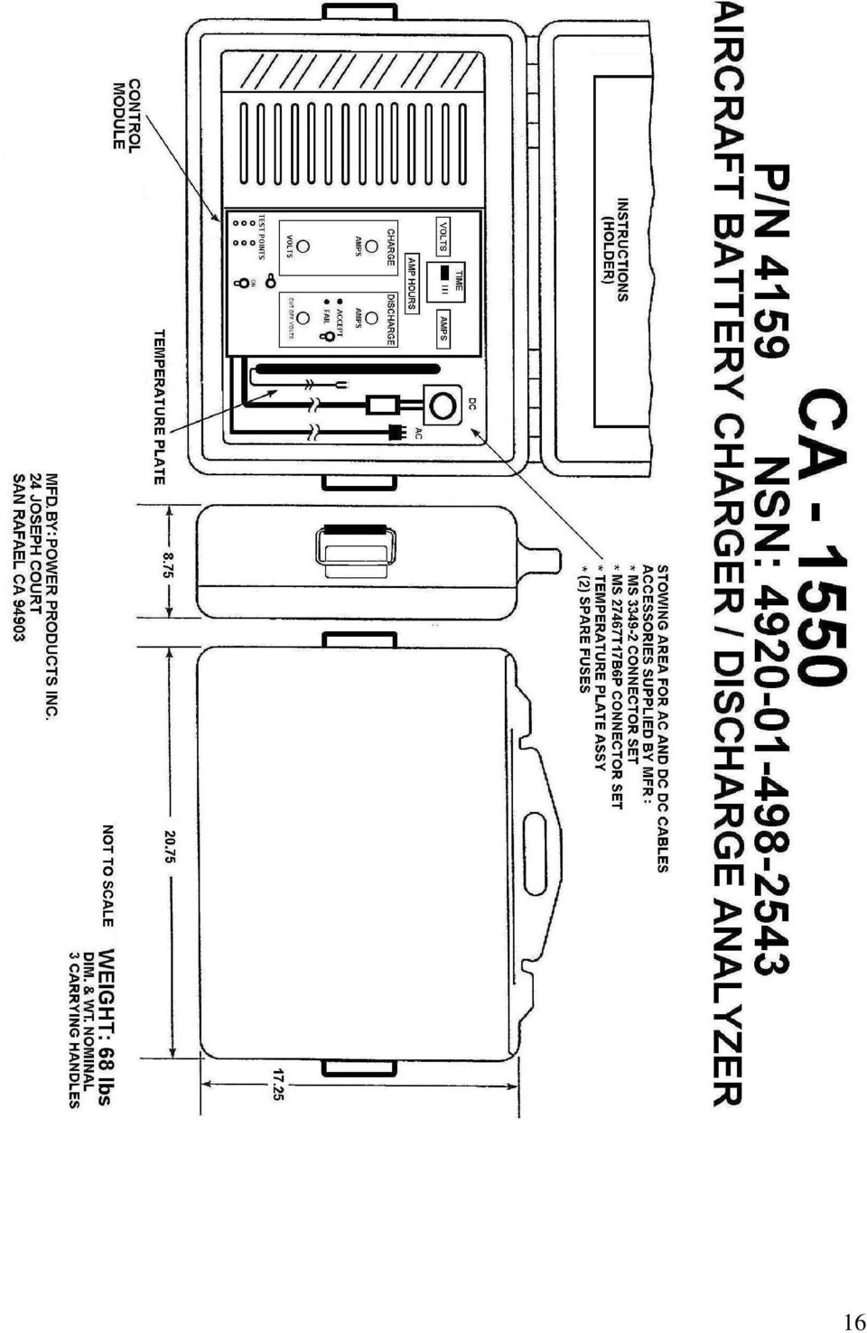
2 TABLE OF CONTENTS SECTION HEADING PAGE I GENERAL / QUICK INSTRUCTIONS 3-4 II CHARGING 4-8 III DISCHARGE 8-10 IV CONDITIONING CHARGE V SPECIFICATIONS VI CHANGING AC LINE VII VERIFYING METER READING FIG. CONTROL BOX 15 FIG. OUTLINE DRAWING 16 CERTIFICATION OF VERIFICATION 17 ACCESSORIES INCLUDED WITH UNIT 18 PPF18AB ADAPTER DRAWING 19 2

3 COVER MUST BE FULLY OPEN WHEN IN USE! OPERATING INSTRUCTIONS P/N 4159 Navy Battery Charger / Analyzer MODEL CA 1550 Charger Input, AC 115 V 50/60 HZ 15A Max. (For 230 V Input- See VI AC Line Change) Battery Charging Current 0-25 amperes, Discharge Current 0-50 amperes Follow NAVAIR 17-15BAD-1 for Detailed Instructions and Battery Specs Refer to Illustrations. Callouts are referred to in these instructions. e.g. (2 is the timer) I. GENERAL / QUICK INSTRUCTIONS Note: Other voltage or chemistry batteries than 24 or 12 Volt SLAB or NiCads may be charged and discharged with the Time, Current & Voltage Settings may be changed as required. 1. CHARGING: 24 Volt SLAB or Nicads a) Set Timer (2) to 180 minutes. b) Set Charge Voltage (6) to 28.5 Volts. c) Set Charge Current (5) to maximum. Battery is charged when current is tapered to low value and remains low as timer times-out. If not tapered, timer may be set to more time. 2. TOPPING: SLAB (Balancing / Equalizing Cells) a) Set Charge Voltage to Maximum b) Set Charge Current to C/10 Battery is equalized when charge voltage remains the same until timer is timed-out. 3. TOPPING NiCads (to 1.55 Volts / Cell) Same as SLAB, except charge may be set to C/3. Battery is topped when each cell reaches 1.55 Volts VOLT BATTERY CHARGING: Same as above, except set charge voltage to 14.7 Volts. 3

4 5. DISCHARGE / CAPACITY TEST 24 VOLT SLAB a) Set Timer to 60 minutes. b) Set low cutoff Voltage (12) to 18.0 Volts. c) Set Constant Current Discharge (15) to the C Rate (e.g. 30 amp-hr battery set to 30.0 amps). d) Accept If the Timer times-out before the battery voltage lowers to cutoff occurs before the timer times-out. e) Fail If cutoff occurs before the timer times-out. 24 VOLT NiCads Same as SLAB, except Set Voltage Cutoff to 1.0 Volt / Cell. 12 VOLT BATTERIES Same, except Set Cutoff to 9.6 Volts. II. CHARGING, GENERAL: The voltage and current adjustments will provide the voltage and currents for Ni- Cad or Vented or Sealed Lead Acid batteries and other battery chemistries and voltages. The 4159 unit will charge all 12 and 24 volt batteries including starting batteries, single cells, emergency batteries such as Inertial Navigation, Inertial Reference (24 cell NiCad). The 4159 will charge in either the Constant Potential (voltage) or Constant Current (amperes) mode depending on the setting of the Charge Voltage Adjust (6) or Charge Current Adjust (5). A. OPERATION: 24 VOLT SEALED LEAD-ACID BATTERIES (SLAB) Set-Up and Procedure (with battery disconnected) Note 1: Potentiometer knobs have knob locks. The settings will remain for any subsequent operations. Note 2: The 4 potentiometer adjustments on the panel are multi-turn (10 turns). 1. Remove the temperature plate from the cable well, plug the cable from the temperature plate into the panel jacks Overtemp Cutoff Thermostat (9), place the battery on the plate. 2. Set On / Start Off / Reset Switch (10) to Off Position. 4

5 3. Plug 4159 into a 115 V outlet - max AC current draw is 15 Amps. For 230 Volt operation, internal jumper connection are changed (See VI for diagram). Do Not Connect Battery 4. Set Charge / Discharge switch (11) to Charge (center position). 5. Set Charge Current Adjust potentiometer (5) completely CCW to minimum. 6. Set Timer (2) to 180 Min (3 hrs). Time may be increased, even during operation (Also decreased, if it is not at or below the led time displayed). 7. Set On/Off Switch (10) to On, (Meter LED s, Digital Time and Ampere hour Meter Displays Illuminate). 8. Set Charge / Discharge Switch (11) to the left View Charge Voltage Setting position and hold it there (this is a momentary position and will snap back to Charge when released). While holding it set Charge Voltage Adjust potentiometer (6) to 28.5 Volts. 9. Release the Charge / Discharge Switch (11), the toggle will return to center charge. 10. Switch On / Off Switch (10) to Off. Connect Battery. 11. Switch On / Off Switch (10) to On. Voltmeter (3) will now read the open circuit battery voltage. 12. Adjust the Charge Current Adjust Knob (5) CW to maximum, or to the current required, per NAVAIR BAD-1. When set to maximum, the Ammeter (17) reads charge current to a maximum of approximately 25 amps or to lesser amperes that the battery accepts due to its capacity/size, state of charge and condition. The Ampere hour meter (16) records Amp- Hours of charge into the battery. 13. As time progresses charge voltage climbs to 28.5 volts. The Voltage holds Constant at 28.5 volts, Current begins to lower (taper). This is a Constant Potential Charge. When charge current tapers to a low level (typically 1-3 amps for larger batteries (20-60 AH) or under 1 amp for smaller, charge is complete. Usually 2-3 hours. Charge stops at end of timing. 5
 to On, (Meter LED s, Digital Time and Ampere hour Meter Displays Illuminate). 8.")
6 Note: Charging old batteries or batteries that have been in a very low state of charge 4, 6, or 8 volts and/or batteries that have been dead in excess of 24 hours to 30 days or more, should be observed for a possible temperature rise during charge. See conditioning section IV. 14. Ampere Hour Meter (16): This provides the precise ampere hours of charge into the battery, and is an indicator of acceptance of charge. When used with the tapered current level and time, it is also an indicator of battery condition. If time, tapered current and ampere hours of charge do not all approximately coincide, there is a problem with the battery, such as sulfation, shorted cell or the end of battery life. With tapered battery (fully charged), ampere hours should be about % of the ampere hour rating of the battery, if the battery was initially completely discharged. See NAVAIR BAD-1 manual for details. B. 12 VOLT LEAD ACID BATTERIES Procedure is exactly the same as for 24 Volt Batteries, except set voltage to 14.7 Volts. C. CELL BALANCING Battery voltage is the average of the sum of the individual cells. There are 12 cells in a 24 volt L-A battery, 6 cells in a 12 volt L-A. The internal cells of the lead acid battery may be imbalanced after charge but it is not possible to verify this as there is no access to individual cells. Therefore, a balancing mode procedure for 12 or 24 volt lead acid batteries should be performed in a Constant Current mode as follows: a. At completion of charge at 28.5 volts (or 14.7 V), when the battery has tapered to low amperes, the battery is charged even though the time is less than as set. b. Note the ampere hours. They should be more than the ampere hour rating of the battery if the battery was completely discharged when placed on charge. If the amp hr reading is not higher than the battery amp hr rating, leave on charge until the end of the time setting. Note: To reset (extend) the time setting for the same time period as set on the timer without losing the amp hr reading, quickly toggle the on/off switch to off/reset,then back to on, one time.( The amp hr meter has a built-in time delay of approx. 2 seconds). Time may be increased during operation, but not decreased. 6

7 c. Switch unit off (10). d. Set Charge Current Adjust (5) to Minimum, CCW e. Switch Unit On (10) f. Set Charge / Discharge Switch (11) to View Voltage Setting. Hold this position while setting the Charge Voltage Adjust knob (5) to approx Volts (or V). g. Set Timer (2) to 120 minutes. h. Switch to On (10) and set Charge Current Adjust knob (5) to C/10 amperes (e.g.: 30 amp hr battery, set to 3.0 amperes, 10 amp hr battery set to 1.0 ampere). i. Voltage will soon rise above 28.5 V (or 14.7 V for 12 volt batteries). The voltage may continue to rise to the maximum of the previously set Volts (or V) or may remain at a lower voltage such as 30 or 31 volts, but the current will remain constant as set. j. At end of the set time or if the Voltage holds constant for three ½ hours periods, set unit to off (10) and remove battery, which is completely charged, cell- balanced, and Ready For Issue. D. CHARGING NICKEL CADMIUM BATTERIES Note 1: A Digital Multimeter (Fluke 77/AN) is required, set to DC Volts scale to read each cell voltage. 1. Perform All Steps as for Charging Lead Acid except as below. a. Set Timer to at least 120 Minutes. b. Set Voltage to 29.5 Volts (19 Cell) or 31.0 Volts (20 Cell). c. Charge the same as the SLAB. d. Near the end of timing, if battery is not fully charged as verified with the AH meter and all cells are not above 1.5 Volts, the 4159 charger can be used as a constant current charger to top the battery as follows: 1) If the timer (2) was timed-out, to check the cell voltages, set On -Off / Reset Switch (10) quickly 1 time so as not to lose the ampere hour reading and to return the timer (2) to zero timing. 2) Adjust the voltage adjust potentiometer (6) to volts (approx. max CW on voltage adjust knob). 3) Adjust the Charge Current potentiometer (5) as desired, 1, 3, 5, amps etc. (C/3, C/10, etc). The C/3 rate will bring the battery to full topping faster 7
.")
8 than C/10. For a 40 amp-hr battery C/3 would be 13.3 amperes, C/10 would be 4.0 amperes. 4) During this topping charge, check the voltage of each cell with the Fluke 77/AN meter. When every cell has reached at least 1.5 volts (1.55 optimal), the battery is charged regardless of the time. The battery is now Ready For Issue. Note 2: The ampere hour meter has a time delay of about 2 seconds. For longer time periods resetting the 4159 timer will lose the ampere hour reading. Therefore record ampere hours, then reset. Add the new amp hour reading to the recorded reading. This is optional, as the full charging amp-hrs have been observed. Note 3: For a 30 ampere hour battery, if current is reduced to 10 amps, that's C/3. The charger should now be in a constant current mode "if the voltage was adjusted up to volts." In this mode the battery would charge as long as you have the timer set for. Please study NAVAIR 17-15BAD-1 to become acquainted with the charge/discharge parameters, cell voltages, etc. for the particular battery you are planning to charge on the e. If battery did not fully charge per paragraph 1 a-c you may consider a Constant Current charge discussed in ID, par D. f. Check each cell with the fluke 77/AN multimeter volts per cell is optimum, the range is 1.5 to 1.85 Volts per cell. When all cell voltages are within this range, the battery is considered charged. See NAVAIR 17-15BAD-1 manual for cells out of range. III. DISCHARGE Note 1: Discharging with the 4159 unit determines the ampere hour capacity of the battery and also reconditions the battery by breaking-up sulfation in SLABS and crystalline adhesion in NiCads. Battery must be fully charged before discharge testing. The discharge is constant current, as the current will remain constant as set by the Discharge Current potentiometer (15) from the start of the discharge procedure to the termination by time (Accept), or low voltage cutoff (Fail). 8

9 Note 2: Ammeter reads with a minus sign display in discharge. A. OPERATION a. Set On /Off Switch (10) to Off. b. Connect Battery (battery must be fully charged). c. Discharge Current Adjust knob (15) to min. (CCW) d. Switch Charge / Discharge switch (11) to Discharge.. e. Set Timer (2) to 60 minutes (or other time if required by special instructions). f. Switch (10) to On. Voltmeter reads the battery open circuit voltage. Ammeter reads zero or low decimal. g. Press Cutoff View Switch (13). h. Read Cutoff Voltage on Voltmeter (3). i. Set Cutoff Voltage Adjust knob (12) to 18.0 volts for a 24 volt battery (or other voltage if required by special instructions). j. Switch to Off / Reset (This step may be eliminated if cutoff voltage is as required, and only if a few seconds of time was spent in checking), and proceed to step k. k. Adjust Discharge Current knob (15), Adjust to Required Amperes (Usually C Rate, Same as 1 Hour Capacity of the Battery) e.g.: For a 40 amp-hr battery set discharge current (15) to 40.0 amperes. Ampere Hour Meter reads discharge ampere hours. B. ACCEPT If the Battery Maintains Voltage above the Set Cutoff Voltage for the amount of time set on the Timer, the Accept Led (14 green) illuminates, meters freeze their readings, high frequency buzzer sounds. (Buzzer indicates that meters and timer are frozen.) 9
 to 18.0 volts for a 24 volt battery (or other voltage if required by special instructions). j.")
10 C. FAIL The battery fails the discharge test because of insufficient capacity if the voltage decreases to below the preset voltage cutoff (usually volts below preset cutoff depending on the rate at which battery voltage is falling), before the timer times-out, the Fail (14 Red) Led illuminates, Meters and Timer Hold (Freeze), buzzer sounds. The actual ampere hour capacity of the battery is indicated by Amps x Time divided by 60. Ampere hours are also directly read on the amphour Meter (16). This is the actual ampere hour capacity of the battery. TEMPERATURE CUTOFF A temperature sensing plate is provided which will Cut off the charge or discharge current when the battery reaches 113 degrees F. This is a cautionary indication to observe this battery. Plug the temperature plate into test points marked Overtemp Cutoff Thermostat. If not plugged-in, charge or discharge proceeds without temperature cut-off. Note: If temperature cutoff occurs, the Ampere Hour Meter keeps its reading. The timer continues to run, while the battery is cooling (it may time-out). When the battery cools, the charge or discharge resumes (if its not timed-out). A new time setting may be needed to achieve the required ampere hours. D. SPECIAL ADJUSTMENTS For a battery of higher capacity than 50 ampere hours, set the time of discharge proportionately higher, e.g. for 60 Ampere hours- Set charge to 50 amps, and timer to 72 minutes, which is 50 A x 72 minutes = 3600 amps min. divided by 60 = 60 amp-hours. For 70-ampere hours, set unit to 50 amps, timer to 84 minutes. (Or for a 60 Ampere hour battery you could set the amps at 30 and the timer for 120 minutes. This is discharging at the 2-hour rate. Then the voltage cut-off should be 19 volts instead of 18. See NAVAIR 17-15BAD-1 for special case-by-case situations. IV. CONDITIONING CHARGE Lead acid batteries become sulfated either because they have not been charged for a long period of time (many months) or left discharged for even one or two days. They have virtually no capacity and will not accept a charge, usually going up to full chemical voltage very quickly with little charge current. They can usually be recovered with a conditioning charge procedure as follows: 10

11 a. Place the battery on the temperature plate, plug plate into thermostat jacks on the 4159 panel. b. Set the 4159 charge voltage to approximately volts. (Max V. setting) c. Set timer to 999 minutes d. Set charge current to 1.0 ampere if the battery will accept 1 ampere. Indications: The battery voltage may rise up to the 34 volts immediately or more slowly. However, voltage may eventually begin to reduce, indicating acceptance of charge. When it is approximately volts, set the charge-discharge switch (11) to View Charge Voltage and set Charge Voltage potentiometer (6) to 28.5 Volts. Increase the charge current adjust to maximum until the battery tapers. (If conditioning is unattended, the battery may remain at the volts until current is manually increased). e. After acceptance of charge, allow battery to rest for 2-3 hours, then discharge at the C rate for 1 hour (normal discharge capacity test.) If the battery passes ( Accept ) then recharge. If it fails, recharge normally, then retest. If it fails again, the battery cannot be recovered for its intended use. Note: See BAD 1 Manual for Complete Conditioning Techniques. V. -SPECIFICATIONS P/N 4159 MODEL: CA-1550 NSN: AC INPUT: 50/60 HZ V 15A MAX V 8A MAX DC OUTPUT: 115/230 V AC INPUT * 0-25 Amperes * 0-35 Volts DISCHARGE 0-50 Amperes for 24 V Batteries Less Than 50 Amperes for Lower Voltage Batteries. FUSES: AC LINE 15A 250V TYPE MDA 1.25 x 0.25 DC charge 40A 32V TYPE AGC 1.25 x 0.25 DISCHARGE 70A 32V. MFR: Little fuse MAXI 11
 to View Charge Voltage and set Charge Voltage potentiometer (6) to 28.5 Volts.")
12 DIMENSIONS: 20 ½ L x 16 ¾ W x 8 ½ D WT 67 LBS *Actual Current and Voltage, charge and discharge, start at zero, but Digital Meters may not read to zero. VI. CHANGING THE AC LINE INPUT FROM 115 TO 230 VOLTS. WARNING: Before change-over, the AC line plug must be physically unplugged from any wall outlet or switch box or serious injury or death may result from AC line electrical shock. a. Unless otherwise specified 4159 is shipped connected in the 115 Volt AC position and a standard USA 125 Volt 15 ampere 3 wire grounded plug is connected to the AC line cord. b. To change the AC line input from 115 Volt to 230 Volt perform the following: 1. Remove the large louvered panel on the power section of the unit. Wired to the large main transformer is the terminal strip with two jumpers. The diagram below denotes the jumper arrangement for AC line input of 115 or 230 Volts. The user will have to adapt or change the AC plug to conform to the AC line mains receptacle. For 230 Volt operation the two jumpers may be placed together on the 2 and 3 terminals so that the second jumper is not lost if change over back to 115 Volts is required in the future. 12

13 VII. VERIFYING METER READING (NOT CALIBRATION) 1. GENERAL: The CA 1550 has been factory calibrated prior to shipment and the unit can be checked for verification of readings of the voltmeter and ammeter with a Fluke 77/AN multimeter. The ampere-hour meter and ammeter must be checked with a load. 2. CHECKING THE VOLTMETER WITHOUT THE BATTERY CONNECTED: a) On / Off switch OFF (10). b) Charge / Discharge switch to Charge (11). c) Charge Current Adjust Max. (5). d) Insert external DC Voltmeter leads into the panel volts test points (7). e) On / Off switch to On (10). f) Verify that the panel meter and test meter such as fluke 77/AN on the DC Volts scale read within Volts. g) Adjust Voltage to confirm that the readings coincide over a voltage range e.g.:22-30 Volts. h) Reset Voltage adjust as required when the check is completed e.g.: 28.5 Volts. 3. CHECKING VOLTMETER WITH THE BATTERY CONNECTED: a) Perform as above, except start with the Charge Current Adjust (5) set to minimum. Increase current to increase and check the voltage. (Do not exceed any maximum current requirements). 13
 Charge Current Adjust Max. (5). d) Insert external DC Voltmeter leads into the panel volts test points (7). e) On / Off switch to On (10).")
14 4. CHECKING THE AMMETER: a) In order to check the ammeter, a load is necessary in order to draw current. A battery may be used but if the battery is fully charged or is rapidly tapering, it may be difficult to check the current. A discharged battery with the 4159 unit, when set to charge, or a charged battery with the unit set to discharge is the most convenient. Also, a high wattage load resistor may be used for both voltmeter and ammeter checks. The voltage adjust when the unit is in charge may be used to verify both volts and amperes. A suggested resistor is about 2 Ohms, whereby 24 Volts will draw 12 amperes. Wattage should be 300 Watts or higher, or as rated if fan-cooled. b) Connect the test meter such as fluke 77/AN to the amps (MV) test points. The test meter must be on the DC Millivolt scale. 5. CHECKING THE AMPERE-HOUR METER: a) As with the Ammeter, a load is necessary to check the amp-hr meter. b) If a battery is used, the amp-hr meter reads on Charge or Discharge without a minus sign for discharge. Note: If the 4159 Charge / Discharge Switch (11) is toggled from Charge to Discharge, the Discharge amp-hrs will subtract from the Charge amp-hrs. If the amp-hr meter was reading Discharge, switching to Charge will subtract from the Discharge reading. c) To check the amp-hr meter accuracy, set the timer to 6 minutes. Connect a resistive load in charge, or battery in Discharge for a Constant Current of 10.0 amperes. This will supply 60 ampere minutes or 1 ampere hour. The amp-hr meter should read 1.0 ampere hours at the end of 6 minutes. The accuracy will be affected by any variation in setting-up this procedure, plus the inherent instrument accuracy of + - 2%. 14

15 4159 CHARGER / ANALYZER CONTROL BOX ITEM NO. DESCRIPTION 1. ENCLOSED ALUMINUM WEATHER-PROOF ENCLOSURE DIM: 13L x 7W x 7D 11 LBS 2. TIMER 3. VOLTMETER 4. MS CONNECTOR ( CABLE TO POWER COMPONENTS ) 5. CHARGE CURRENT ADJUST 6. CHARGE VOLTAGE ADJUST 7. VOLTMETER TEST POINTS 8. AMMETER TEST POINTS 9. TEMPERATURE PLATE POINTS 10. ON/OFF SWITCH 11. VIEW CHARGE / CHARGE / DISCHARGE SWITCH 12. CUTOFF VOLTAGE ADJUST 13. VIEW CUT OFF VOLTAGE ( VIEW ON VOLTMETER ) 14. ACCEPT / FAIL LAMPS 15. DISCHARGE CURRENT ADJUST 16. AMPERE HOUR METER 17. AMMETER 15
 14. ACCEPT / FAIL LAMPS 15.")
16 ffff 16
17 CERTIFICATION OF FACTORY VERIFICATION AIRCRAFT BATTERY CHARGER / DISCHARGE TESTER MODEL: CA-1550 MIL P/N: 4159 MIL MFD. BY: POWER PRODUCTS INC. 27 Pamaron Way, Suite E Novato, CA Cage Code #: 3C8X4 Tel: Fax: paul@power-products.com AC INPUT: 50/60 HZ 115 V 14A MAX., 230 V 7A MAX. DC OUTPUT: CHARGE 0-25A DISCHARGE: 0-50A MAX Refer to Operating Instructions for more complete specifications. Standards Used Traceable to National Institute of Standards and Technology (NIST) Calibrated Instruments: a) Digital Multimeter Fluke 8010A b) Digital Multimeter Fluke 73III c) Oscilloscope, Leader model LS1020 Auxiliary Non-Calibratable Equipment Used: Batteries: d) Shunt 100A 100MV EMPRO (OHMIC VALUE = OHMS) NiCad Super Cell Marathon Lead Acid RG380E 24V Concorde Load Bank AMP. Power Products Power Products Factory Test Report / Method No VERIFICATION: AMMETER VOLTMETER AMPERE HOUR METER TIMER WITHIN TOLERANCE WITHIN TOLERANCE WITHIN TOLERANCE WITHIN TOLERANCE SERIAL NO: VERIFIED BY: DATE OF MANUFACTURE: DATE OF VERIFICATION: Power Products Inc. certifies that the above listed P/N 4159 Battery Charger / Discharger meets or exceeds all published specifications and complies with ISO 9000 where applicable. Accuracies of calibration of instruments used are traceable to the National Institute of Standards and Technology. 17
 Calibrated Instruments: a) Digital Multimeter Fluke 8010A b) Digital Multimeter Fluke 73III c) Oscilloscope, Leader")
18 ACCESSORIES INCLUDED WITH CA-1550 UNIT: OPERATING INSTRUCTIONS TEMPERATURE SENSING PLATE SPARE 15A AND 40A FUSES ADAPTOR FOR RING TERMINALS ADAPTOR FOR F18 MODEL A & B BATTERY ADAPTOR FOR BATTERY QUICK DISCONNECT 18

Essential Electrical Concepts
 Essential Electrical Concepts Introduction Modern vehicles incorporate many electrical and electronic components and systems: Audio Lights Navigation Engine control Transmission control Braking and traction
OUTPUT CABLE CONNECTIONS:
 Tender Plus: Models: 12V1.25A and 6V1.25A The Tender Plus 12 Volt, 1.25 Amp 6 Volt, 1.25 Amp GENERAL DESCRIPTION: The Tender Plus battery charger is a desktop, portable, linear power converter that has
Battery Charger For Nickel Cadmium and Nickel-Metal Hydride Rechargeable Batteries Model PSN Series
 Battery Charger For Nickel Cadmium and Nickel-Metal Hydride Rechargeable Batteries Model PSN Series Operating Instructions WARNING CONCERNING THE REMOVAL OF COVER: CAUTION: TO PREVENT THE RISK OF ELECTRIC
TROUBLESHOOTING GUIDE
 TROUBLESHOOTING GUIDE LESTRONIC II BATTERY CHARGER FOR MOTIVE POWER BATTERIES PLEASE SAVE THESE IMPORTANT SAFETY AND OPERATING INSTRUCTIONS For correct operation of the equipment, it is important to read
Match. GE Digital Energy. Uninterruptible Power Supply 500-1500 VA. Technology for the Digital World. Match UPS. GE Digital Energy.
 Match Uninterruptible Power Supply 500-1500 VA Manufactured by: General Electric Company Telephone +41 (0)91 / 850 51 51 CH 6595 Riazzino (Locarno) Fax +41 (0)91 / 850 51 44 Switzerland Website www.gedigitalenergy.com
BC-5000 OPERATIONS MANUAL BATTERY CAPACITY TESTER COFKO LLC.
 BC-5000 BATTERY CAPACITY TESTER OPERATIONS MANUAL COFKO LLC. COPYRIGHT 2010 1 UNPACKING As you unpack your new BC-5000 battery capacity tester, inspect the tester for signs of shipping damage. If shipping
LESTRONIC DV AUTOMATIC 12 OR 24 VOLT DUAL OUTPUT DUAL MODE BATTERY CHARGER MODEL 16350 TYPE 12/24EL40-10ET
 LESTRONIC DV AUTOMATIC 12 OR 2 VOLT DUAL OUTPUT DUAL MODE BATTERY CHARGER MODEL 16350 TYPE 12/2EL0-10ET PLEASE SAVE THESE IMPORTANT SAFETY AND OPERATING INSTRUCTIONS For correct operation of the equipment,
Lab E1: Introduction to Circuits
 E1.1 Lab E1: Introduction to Circuits The purpose of the this lab is to introduce you to some basic instrumentation used in electrical circuits. You will learn to use a DC power supply, a digital multimeter
How To Use A Power Supply Unit (Upu)
") BRAVER UPS (Uninterruptible Power System) User s Manual Safety CAUTION! This UPS utilizes voltages that may be hazardous. Do not attempt to disassemble the unit. The unit contains no user replaceable parts.
BRAVER UPS (Uninterruptible Power System) User s Manual Safety CAUTION! This UPS utilizes voltages that may be hazardous. Do not attempt to disassemble the unit. The unit contains no user replaceable parts.
Battery Chargers. Revised 8/00 Form Number 56041170 FORM NO. 56041170 / BATTERY CHARGER SERVICE MANUAL / PARTS LIST - 45
 Battery Chargers SERVICE MANUAL / PARTS LIST AUTOMATIC Advance MODELS 0980, 098, 797, 8809, 90, 880, 880, 099, 08,, 09788, 098, 7, 097, 70, 790, 889 Lester MODELS 007,, 8, 8, 89, 80, 9, 00, 00, 008 MANUAL
STEALTH I DC MANUAL TECH SUPPORT 1-888-588-4506.WEB www.stealth1charging.com BLACK UNIT IS 24/36 ONLY
 STEALTH I DC MANUAL TECH SUPPORT 1-888-588-4506.WEB www.stealth1charging.com BLACK UNIT IS 24/36 ONLY PLEASE READ AND UNDERSTAND YOUR NEW PRODUCT IMPORTANT MESSAGE: Before installing your newly purchased
Instruction Manual. 2in1 LAN Tester & Multimeter. Model: LA-1011
 Instruction Manual 2in1 LAN Tester & Multimeter Model: LA-1011 1 Contents Introduction... Features... Safety Precautions.. Meter Description... Electrical Specification... Operation.. AutoRanging Multimeter.
Renewable Energy Test Station (RETS) TEST PROCEDURES FOR SOLAR TUKI
 TEST PROCEDURES FOR SOLAR TUKI") Renewable Energy Test Station (RETS) TEST PROCEDURES FOR SOLAR TUKI March 2007 A. Test Procedures for Solar Tuki Lamp S. No. Test Parameters Technical Requirements Instruments Required Test Methods A.
Renewable Energy Test Station (RETS) TEST PROCEDURES FOR SOLAR TUKI March 2007 A. Test Procedures for Solar Tuki Lamp S. No. Test Parameters Technical Requirements Instruments Required Test Methods A.
BATTERY BOX INSTALLATION WARNING WARNING CAUTION ATTENTION AVERTISSEMENT ADVERTENCIA PRECAUCIÓN SOLBBOX12V CARTON INVENTORY COMPLETED OVERVIEW
 WARNING CARTON INVENTORY CAUTION with: Charger, Cable 15', Fuses (2), Battery Strap and Strain Relief (2) Model SOLBBOX 12V Battery Not Included AVERTISSEMENT ATTENTION DC Power Adapter 12Vdc to 32Vdc
SX460. Generator Automatic Voltage Regulator Operation Manual
 SX460 Generator Automatic Voltage Regulator Operation Manual Self Excited Automatic Voltage Regulator Compatible with Newage SX460* * Use for reference purpose only and not a genuine Newage product. 1.
OWNERS MANUAL FOR CORDLESS INFLATOR AIR260
 OWNERS MANUAL FOR CORDLESS INFLATOR AIR260 POWER SUPPLY OUTLET: AIR OUTPUT: BATTERY: RECHARGING TIME: WEIGHT: DIMENSIONS: FUSE: LIGHT BULB: SPECIFICATIONS DC 12V 15 AMP 180W MAX 260 PSI MAX PRESSURE SEALED
DC Electronic Loads 8500 series
 Data Sheet DC Electronic Loads 8500 series 2400W 600 W - 1200 W 300 W Versatile & Economical DC Electronic Loads The 8500 series Programmable DC Electronic Loads can be used for testing and evaluating
Lab 3 - DC Circuits and Ohm s Law
 Lab 3 DC Circuits and Ohm s Law L3-1 Name Date Partners Lab 3 - DC Circuits and Ohm s Law OBJECTIES To learn to apply the concept of potential difference (voltage) to explain the action of a battery in
Troubleshooting Guide, Freedom and Fleet Power Inverter/Chargers
 Technical Note Freedom/Fleet Power 512-0084-01-01 Rev 1 Troubleshooting Guide, Freedom and Fleet Power Inverter/Chargers Overview This document is a guide for troubleshooting inverters, battery chargers,
510 / 511 Cardiorespiratory Monitor Preventative Maintenance Test Procedure
 CAS MEDICAL SYSTEMS, INC. 510 / 511 Cardiorespiratory Monitor Preventative Maintenance Test Procedure using the 2301Multi-Function Tester 44 East Industrial Road Branford, CT 06405 USA www.techsrv@casmed.com
IMPORTANT SAFETY INSTRUCTIONS WARNING READ AND SAVE THESE OPERATING AND SAFETY INSTRUCTIONS BEFORE USING THIS HEATER.
 THERMAWAVE CERAMIC HEATER Model HZ-850 Series Model HZ-860 Series IMPORTANT SAFETY INSTRUCTIONS WARNING READ AND SAVE THESE OPERATING AND SAFETY INSTRUCTIONS BEFORE USING THIS HEATER. Warning Failure to
Installation and Operation Guide for PD4000 Series Power Control Center
 Extended warranties are available for purchase at www.progressivedyn.com Installation and Operation Guide for PD4000 Series Power Control Center Member Thank you for selecting Progressive Dynamics as your
Instructions & Safety Information Models A220-20D and A220-20L Version 2
 Quick 220 Voltage Converting Power Supply Instructions & Safety Information Models A220-20D and A220-20L Version 2 Quick 220 Systems LLC PO Box 47489 Phoenix, Arizona 85068-7489 800-347-0394 602-938-6057
INSTALLATION & SERVICE MANUAL. Display Panel
 INSTALLATION & SERVICE MANUAL Display Panel The PowerLine EMS TM is a specialized power distribution and energy management system intended to be used in recreational vehicles. The Control Module is housed
WHOLESALE DIRECT INC. 5620 WEST 65TH STREET
 Auto Pump V 200 100 0 100 Max Rating Vehicle mount compressor ensures truck air brake system is properly pressurized for immediate dispatch from station Pressure switch regulated operation automatically
Power your CPAP machine no matter where your world takes you!
 Power your CPAP machine no matter where your world takes you! Giving CPAP users the freedom to experience new adventures on the road! Your CPAP machine doesn t have to keep you from enjoying the great
BLOOD COLLECTION MIXER
 USER S MANUAL BLOOD COLLECTION MIXER Model CM735 No. CAT.CM73522Ce Centron Technologies Corporation 319-25 Sadang-4-dong, Dongjak-ku Seoul, Korea 156-823 Tel. +82-2.522.7807 Fax +82-2.522.7806 Table of
Solar Wind Microhydro Water Pumping Inverters Batteries Professional system design and installation
 Solar Wind Microhydro Water Pumping Inverters Batteries Professional system design and installation BATTERY CHARGING GUIDELINES FOR GLOBAL/DAVIDSON TUBULAR PLATE BATTERIES Introduction Your Global/Davidson
INSTRUCTIONS FOR MAGNUM DS TRIP UNIT TESTING USING TEST KIT SYLES 140D481G02R, 140D481G02RR, 140D481G03 AND 140D481G04
 I.L. 32-693 A INSTRUCTIONS FOR MAGNUM DS TRIP UNIT TESTING USING TEST KIT SYLES 140D481G02R, 140D481G02RR, 140D481G03 AND 140D481G04 DANGER DO NOT ATTEMPT TO INSTALL OR PERFORM MAINTE- NANCE ON EQUIPMENT
XPower 1500 Portable Household Power
 by t 1 408-987-6030 f 1 360-925-5143 www.xantrex.com XPower 1500 Portable Household Power 445-0127-01-01 REV. 2 Printed in China Owner's Guide by XPower 1500 Portable Household Power Owner s Guide About
Daker DK 1, 2, 3 kva. Manuel d installation Installation manual. Part. LE05334AC-07/13-01 GF
 Daker DK 1, 2, 3 kva Manuel d installation Installation manual Part. LE05334AC-07/13-01 GF Daker DK 1, 2, 3 kva Index 1 Introduction 24 2 Conditions of use 24 3 LCD Panel 25 4 Installation 28 5 UPS communicator
FIREDEX 2200. Conventional Fire Panels
 68 Flexible, high specification system Choice of 1, 2, 4 or 8 zones Simple one-shot auto-reset user test facility Approved to EN54 Maintenance free poly switch circuit protection, with auto reset Class
Circuit symbol. Each of the cells has a potential difference of 1.5 volts. Figure 1. Use the correct answer from the box to complete the sentence.
 Q.(a) Draw one line from each circuit symbol to its correct name. Circuit symbol Name Diode Light-dependent resistor (LDR) Lamp Light-emitting diode (LED) (3) Figure shows three circuits. The resistors
WB/WBS 3, 4, 5, 7, 8, 11, 14, 30
 INSTRUCTION MANUAL FOR WB/WBS 3, 4, 5, 7, 8, 11, 14, 30 WATER BATH PLEASE READ THIS MANUAL CAREFULLY BEFORE OPERATION 3, Hagavish st. Israel 58817 Tel: 972 3 5595252, Fax: 972 3 5594529 mrc@mrclab.com
BATTERY CHARGER OWNER S MANUAL
 SAVE THESE INSTRUCTIONS This manual contains important safety and operating instructions for the automatic battery charger. Do not expose charger to rain or snow. Do not use and an attachment not recommended
EXPERIMENT 7 OHM S LAW, RESISTORS IN SERIES AND PARALLEL
 260 7- I. THEOY EXPEIMENT 7 OHM S LAW, ESISTOS IN SEIES AND PAALLEL The purposes of this experiment are to test Ohm's Law, to study resistors in series and parallel, and to learn the correct use of ammeters
Power Supplies. Overview. Measuring Electricity. Understanding Electricity. Two Types of Current. Powering the PC
 Overview Power Supplies Chapter 7 In this chapter, you will learn to Explain the basics of electricity Provide proper power and cooling to the PC Troubleshoot electrical problems Measuring Electricity
Manual Ranging MultiMeter
 Owner s Manual Manual Ranging MultiMeter Model 82345 CAUTION: Read, understand and follow Safety Rules and Operating Instructions in this manual before using this product.! Safety! Operation! Maintenance!
Back-UPS 650 VA 120 V with AVR (BX650CI-LM)
") Back-UPS 650 VA 120 V with AVR (BX650CI-LM) Overview Do not install the unit in direct sunlight, in areas of excessive heat or humidity, or in contact with fluids ON/OFF button Battery connector Circuit
Back-UPS 650 VA 120 V with AVR (BX650CI-LM) Overview Do not install the unit in direct sunlight, in areas of excessive heat or humidity, or in contact with fluids ON/OFF button Battery connector Circuit
EASIDEW PORTABLE HYGROMETER INSTALLATION, OPERATION AND MAINTENANCE MANUAL
 EASIDEW PORTABLE HYGROMETER INSTALLATION, OPERATION AND MAINTENANCE MANUAL Issue February 2004 2 TABLE OF CONTENTS SECTION PAGE 1. INTRODUCTION 3 1.1 General 3 1.2 Ceramic Sensing Element 3 1.3 Calibration
Model HPX10 Series Automatic Battery Charger User s Manual Rev. 1.0 October 17, 2006
 B R A N D Model HPX10 Series Automatic Battery Charger User s Manual Rev. 1.0 October 17, 2006 For Sales, Support and Service phone: 407-331-4793 fax: 407-331-4708 website: www.xenotronix.com email: information@xenotronix.com
Solar Home System. User Manual. AEH-SHS01-10W2L Solar Home System 2 Lamps
 Solar Home System User Manual AEHSHS0110W2L Solar Home System 2 Lamps All rights reserved Specifications subject to change without prior notice 2 Dear Customer, Thank you for purchasing Schneider Electric
12 Volt 30 Amp Digital Solar Charge Controller
 12 Volt 30 Amp Digital Solar Charge Controller User s Manual WARNING Read carefully and understand all INSTRUCTIONS before operating. Failure to follow the safety rules and other basic safety precautions
PHYSICS 111 LABORATORY Experiment #3 Current, Voltage and Resistance in Series and Parallel Circuits
 PHYSCS 111 LABORATORY Experiment #3 Current, Voltage and Resistance in Series and Parallel Circuits This experiment is designed to investigate the relationship between current and potential in simple series
Advantium 2 Plus Alarm
 ADI 9510-B Advantium 2 Plus Alarm INSTALLATION AND OPERATING INSTRUCTIONS Carefully Read These Instructions Before Operating Carefully Read These Controls Corporation of America 1501 Harpers Road Virginia
6/14/02 Chapter 14: Use of Electrical Test Equipment 1/20
 USE OF ELECTRICAL TEST EQUIPMENT Test equipment is necessary for determining proper set-up, adjustment, operation, and maintenance of electrical systems and control panels. The following is a general procedure
Installation and Operation Guide for PD4100 Series Power Control Centers
 Installation and Operation Guide for PD4100 Series Power Control Centers Extended warranties are available for purchase at www.progressivedyn.com Member Thank you for selecting Progressive Dynamics as
The table below lists the symbols used on the Clamp and/or in this manual. Important Information. See manual.
 i800 AC Current Clamp Instruction Sheet Introduction The i800 AC Current Clamp, the Clamp, has been designed for use with multimeters, recorders, power analyzers, safety testers, etc., for accurate non-intrusive
Digital echo-charge. Owner s Manual. Xantrex Digital echo-charge Battery Charger
 Digital echo-charge Owner s Manual Xantrex Digital echo-charge Battery Charger Thank you for purchasing a Xantrex Digital echo-charge. Xantrex Technology Inc. takes pride in manufacturing quality products
Automatic taper of charge rate for superior battery life through good equalization of cells and low water use rate.
 *00151* FEATURES Automatic taper of charge rate for superior battery life through good equalization of cells and low water use rate. Silicon diodes with inherent surge protection operated at a conservative
BROOKFIELD MODEL VTE250 ELECTRIC VISCOSEL PROCESS VISCOMETER. Installation, Operation, and Maintenance Instructions. Manual No.
 BROOKFIELD MODEL VTE250 ELECTRIC VISCOSEL PROCESS VISCOMETER Installation, Operation, and Maintenance Instructions Manual No. M06-512 SPECIALISTS IN THE MEASUREMENT AND CONTROL OF VISCOSITY BROOKFIELD
Table of Contents. The Basics of Electricity 2. Using a Digital Multimeter 4. Testing Voltage 8. Testing Current 10. Testing Resistance 12
 Table of Contents The Basics of Electricity 2 Using a Digital Multimeter 4 IDEAL Digital Multimeters An Introduction The Basics of Digital Multimeters is designed to give you a fundamental knowledge of
Technical Update TAA.TU.11093 Rev. 1
 http://www.gambro.com/en/usa_tech/ 800-525-2623 303-222-6500 Technical Update TAA.TU.11093 Rev. 1 Effective: 05 APR 2013 CO# 13084 Product: Subject: From: Phoenix Dialysis System Required Electrical Safety
OEM Manual MODEL 2350 ELECTRONIC DUAL CYLINDER SCALE
 OEM Manual MODEL 2350 ELECTRONIC DUAL CYLINDER SCALE Scaletron Industries, Ltd. Bedminster Industrial Park 53 Apple Tree Lane P.O. Box 365 Plumsteadville, PA 18949 USA Toll Free: 1-800-257-5911 (USA &
AUTO CHARGE 3 STEP AUTOMATIC BATTERY CHARGER
 FILE: IM_091-120-12E-20 Rev A., 05-06-08 INSTRUCTION MANUAL AUTO CHARGE 3 STEP AUTOMATIC BATTERY CHARGER R MODEL #091-120-12E-20 for ODYSSEY AGM BATTERIES CAUTION This charger is calibrated to the ODYSSEY
Series and Parallel Resistive Circuits Physics Lab VIII
 Series and Parallel Resistive Circuits Physics Lab VIII Objective In the set of experiments, the theoretical expressions used to calculate the total resistance in a combination of resistors will be tested
Product Information Sheet UH28CS-12kV Hi Pot Tester
 Product Information Sheet UH28CS-12kV ETL Prüftechnik GmbH Telefon: +49 711 83 99 39-0 E-Mail: info@etl-prueftechnik.de Carl-Peters-Straße 23 D-70825 Korntal-Münchingen Telefax: +49 711 83 99 39-9 Internet:
User s Manual Before using the inverter, you need to read and save the safety instructions.
 User s Manual Before using the inverter, you need to read and save the safety instructions. STI SERIES (STI200, STI300, STI500, STI700, STI1000) Power Frequency Pure Sine Wave Inverter The information
User s Manual AURORA 1.2K/2.2K
 User s Manual AURORA 1.2K/2.2K Uninterruptible Power System Safety CAUTION This UPS utilizes voltages that may be hazardous. Do not attempt to disassemble the unit. The unit contains no user serviceable
Table Of Contents 6 6 6 7 7 8 8 9-11 12 12-13 14 15 16 17 18 19 20-21 22 22 23 24 24 24
 USER S GUIDE Table Of Contents Package Contents Accessories: Sold Separately Product Specifications Intended Use Compatibility ResMed Device Warning Battery Pack Run Times Power Backup Usage Getting Started
Experiment #3, Ohm s Law
 Experiment #3, Ohm s Law 1 Purpose Physics 182 - Summer 2013 - Experiment #3 1 To investigate the -oltage, -, characteristics of a carbon resistor at room temperature and at liquid nitrogen temperature,
46120-F0 Solar Energy Training System
 46120-F0 Solar Energy Training System LabVolt Series Datasheet Festo Didactic en 120 V - 60 Hz 06/2016 Table of Contents General Description 2 List of Equipment 2 List of Manuals 3 Table of Contents of
HM-W536 Install Guide
 HM-W536 Install Guide 9/13/2013 IMPORTANT SAFETY INSTRUCTIONS Warning - When using electrical devices, basic safety precautions should be followed to reduce the risk of fire, electrical shock or injury.
www.ringautomotive.co.uk Instructions: Retain these instructions for future reference SmartChargePro35 RSCPR35-12v, 2 / 8 / 16 / 35A
 SmartChargePro7 RSCPR7-12v, 7A SmartChargePro10 RSCPR10-12v, 10A SmartChargePro15 RSCPR15-12v, 15A SmartChargePro25 RSCPR25-12v, 2 / 6 / 12 / 25A SmartChargePro35 RSCPR35-12v, 2 / 8 / 16 / 35A SmartChargePro50
OWNER'S MANUAL. Model 20-1050CUL AC Power Inverter/Charger System OM/A96283 REV. A
 OWNER'S MANUAL Model 20-1050CUL AC Power Inverter/Charger System OM/A96283 REV. A Table of Contents Section 1 Introduction... 1 Section 2 Installing the 20-1050CUL... 4 Section 3 Installing the IFM1 Interface
VOLTAGE/CURRENT CALIBRATOR ISO-TECH ILC-421
 VOLTAGE/CURRENT CALIBRATOR ISO-TECH ILC-421 TABLE OF CONTENTS 1. FEATURES... 1 2. SPECIFICATIONS... 1 2-1 General Specifications...1 2-2 Electrical Specifications... 2 3. FRONT PANEL DESCRIPTION... 4 3-1
3000W Power Inverter
 3000W Power Inverter OWNER S MANUAL Model number-4573000 TO REDUCE THE RISK OF INJURY, USER MUST READ AND UNDERSTAND THIS INSTRUCTIONAL MANUAL. THIS MANUAL CONTAINS IMPORTANT INFORMATION REGARDING THE
EMERGENCY EGRESS LIGHTING POWER SUPPLY PART NO. 5925-6 COMPONENT MAINTENANCE MANUAL WITH ILLUSTRATED PARTS LIST
 EMERGENCY EGRESS LIGHTING POWER SUPPLY PART NO. WITH ILLUSTRATED PARTS LIST Initial Issue: June 16, 1995 33-51-80Page 1 May 20/2010 RECORD OF REVISIONS REV. NO. ISSUE DATE A 01-26-96 B 09-21-99 C 10-26-09
Quick Start Guide 00825-0100-4764, Rev DA March 2014. Rosemount 8714D (Calibration Standard) Magnetic Flowtube Simulator
 Magnetic Flowtube Simulator") Quick Start Guide 00825-0100-4764, Rev DA Rosemount 8714D (Calibration Standard) Magnetic Flowtube Simulator Quick Start Guide NOTICE This document provides basic guidelines for the Rosemount 8714D. It
Quick Start Guide 00825-0100-4764, Rev DA Rosemount 8714D (Calibration Standard) Magnetic Flowtube Simulator Quick Start Guide NOTICE This document provides basic guidelines for the Rosemount 8714D. It
HP UPS R1500 Generation 3
 HP UPS R1500 Generation 3 Installation Instructions Part Number 650952-001 NOTE: The rating label on the device provides the class (A or B) of the equipment. Class B devices have a Federal Communications
Specification Requirements DBL 700MX and 1000MX Series UPS
 Specification Requirements DBL 700MX and 1000MX Series UPS Theory of Operation Upon loss of utility power, the UPS inverter shall continue to provide seamless pure sine-wave AC from the batteries without
Fig. 1 Analogue Multimeter Fig.2 Digital Multimeter
 ELECTRICAL INSTRUMENT AND MEASUREMENT Electrical measuring instruments are devices used to measure electrical quantities such as electric current, voltage, resistance, electrical power and energy. MULTIMETERS
LG Air Conditioning Multi F(DX) Fault Codes Sheet. Multi Split Units
 Fault Codes Sheet. Multi Split Units") Multi Split Units If there is a fault on any LG Multi unit, an Error mark is indicated on the display window of the indoor unit, wired-remote controller, and LED s of outdoor unit control board. A two
Multi Split Units If there is a fault on any LG Multi unit, an Error mark is indicated on the display window of the indoor unit, wired-remote controller, and LED s of outdoor unit control board. A two
Measuring Electric Phenomena: the Ammeter and Voltmeter
 Measuring Electric Phenomena: the Ammeter and Voltmeter 1 Objectives 1. To understand the use and operation of the Ammeter and Voltmeter in a simple direct current circuit, and 2. To verify Ohm s Law for
Drayton Digistat +2RF/+3RF
 /+3RF Programmable Room Thermostat Wireless Model: RF700/22090 Model: RF701/22092 Power Supply: Battery - Thermostat Mains - Digistat SCR Invensys Controls Europe Customer Service Tel: 0845 130 5522 Customer
3 WATT LED SPOTLIGHT Model No. SLM - 3801
 3 WATT LED SPOTLIGHT Model No. SLM - 3801 OWNER'S MANUAL Customer Service Tel: 1-800-268-3319 Superex Canada Ltd, Toronto,M2H 3B8 Made in China Table of Contents A). Important Safety Instructions B). Charging
Important Safety Instructions
 PR-D7 GB Revision 1 Important Safety Instructions 1. Read these instructions. 2. Keep these instructions. 3. Heed all warnings. 4. Follow all instructions. 5. Do not use this apparatus near water. 6. Clean
Odyssey of the Mind Technology Fair. Simple Electronics
 Simple Electronics 1. Terms volts, amps, ohms, watts, positive, negative, AC, DC 2. Matching voltages a. Series vs. parallel 3. Battery capacity 4. Simple electronic circuit light bulb 5. Chose the right
IDEAL INDUSTRIES, INC. TECHNICAL MANUAL MODELS: 61-763 61-765
 IDEAL INDUSTRIES, INC. TECHNICAL MANUAL MODELS: 61-763 61-765 The Service Information provides the following information: Precautions and safety information Specifications Performance test procedure Calibration
HCS-3300/3302/3304 USB Remote Programmable Laboratory Grade Switching Mode Power Supply
 1. INTRODUCTION HCS-3300/3302/3304 USB Remote Programmable Laboratory Grade Switching Mode Power Supply User Manual This family of efficient, upgraded SMPS with small form factor, auto cross over CV CC,
SYSTEM 4C. C R H Electronics Design
 SYSTEM 4C C R H Electronics Design SYSTEM 4C All in one modular 4 axis CNC drive board By C R Harding Specifications Main PCB & Input PCB Available with up to 4 Axis X, Y, Z, A outputs. Independent 25
Agilent E3633A and E3634A DC Power Supplies
 Service Guide Part Number: E3634-90010 Seventh Edition, April 21, 2014 Copyright Agilent Technologies, Inc. 1998 2014 All Rights Reserved. Agilent E3633A and E3634A DC Power Supplies Agilent Technologies
User Manual for CH-PFC76810
 AA Portable Power Corp www.batteryspace.com, Email: Sales@batteryspace.com User Manual for CH-PFC76810 1. Overview The CH-PFC76810 charger is suitable for charging lithium ion battery packs such as those
Charge Regulator SCR 12 Marine
 Charge Regulator SCR 12 Marine Manual Many thanks for purchasing a superwind product. The SCR 12 Marine is a charge regulator of highest quality and will perfectly and reliably charge your batteries for
Battery Handbook. By: RON SMITH
 Battery Handbook By: RON SMITH Information compiled from the Battery Charger Handbook and the Battery Handbook written by Alvin G. Graham, Chief Engineer, Ratelco Electronics Inc. Introduction The purpose
M 140i. Multifunction Calibrator. Operation Manual
 M 140i Multifunction Calibrator Operation Manual M-140i Multifunction Calibrator MEATEST, s.r.o. 2 Operation Manual v33 MEATEST, s.r.o. M-140i Multifunction Calibrator Content Operation Manual... 1 Basic
SUGGESTED SPECIFICATION for Series 185 Service Entrance Rated Automatic Transfer Switches
 SUGGESTED SPECIFICATION for Series 185 Service Entrance Rated Automatic Transfer Switches PART 1 GENERAL 1.01 Scope Optional Standby Power Generator Systems A. Furnish and install automatic transfer switches
BATTERY SERVICE. This Automotive Series BATTERY SERVICE has been developed by. Kevin R. Sullivan. Professor of Automotive Technology Skyline College
 BATTERY SERVICE This Automotive Series BATTERY SERVICE has been developed by Kevin R. Sullivan Professor of Automotive Technology Skyline College All Rights Reserved v1.1 Visit us on the web at: www.autoshop101.com
Internet Office UPS System Standby UPS for PCs, workstations and more
 Internet Office UPS System Standby UPS for PCs, workstations and more Model #: INTERNETOFFICE500 500VA standby tower UPS system Offers battery-derived AC output during blackouts and brownouts starting
1. Scope This specification is applied to ICR18650. 2. Product Specification Table 1 No. Item Rated Performance Remark
 1. Scope This specification is applied to ICR18650. 2. Product Specification Table 1 No. Item Rated Performance Remark 1 Rated Capacity Typical Minimum 2 Nominal Voltage 3.7V 3 Voltage at end of Discharge
Industrial Battery Charger. Installation and Operation Manual
 Industrial Battery Charger Installation and Operation Manual 1 INDEX Page Section Description 3 - Safety Instructions 4 1.0 Installation 4 1.1 Receiving 4 1.2 Location 4 1.3 Line Voltage Adjustments 6
Manual. Solar Fountain Mobile Phone Charger
 EN Manual Solar Fountain Mobile Phone Charger Copyrights 2008 Victron Energy B.V. All Rights Reserved This publication or parts thereof may not be reproduced in any form, by any method, for any purpose.
SIMPLE ELECTRONIC IGNITION WIRE DIAGRAM THERMOSTAT (3) PV PILOT BURNER/IGNITOR - SENSOR Q345A (9) SPARK (4) GND (BURNER) CHASSIS GND
 PV PILOT BURNER/IGNITOR - SENSOR Q345A (9) SPARK (4) GND (BURNER) CHASSIS GND") Honeywell Electronic Ignition Troubleshooting Tech Tip April 2007 The Honeywell S8610H Intermittent Pilot Module provides the ignition sequencing, pilot spark, pilot flame monitoring, Pilot Valve (PV)
Honeywell Electronic Ignition Troubleshooting Tech Tip April 2007 The Honeywell S8610H Intermittent Pilot Module provides the ignition sequencing, pilot spark, pilot flame monitoring, Pilot Valve (PV)
OWNER S MANUAL 2.5/3.0 ACS PANEL (ADVANCED CONTROL SYSTEM) 7725 Lougheed Highway Burnaby, BC V5A 4V8 Canada
 7725 Lougheed Highway Burnaby, BC V5A 4V8 Canada") 2.5/3.0 ACS PANEL (ADVANCED CONTROL SYSTEM) OWNER S MANUAL 7725 Lougheed Highway Burnaby, BC V5A 4V8 Canada Tel: (604) 420-1585 Fax: (604) 420-1591 http:// www. statpower.com PROsine 2.5/3.0 ACS Panel
2.5/3.0 ACS PANEL (ADVANCED CONTROL SYSTEM) OWNER S MANUAL 7725 Lougheed Highway Burnaby, BC V5A 4V8 Canada Tel: (604) 420-1585 Fax: (604) 420-1591 http:// www. statpower.com PROsine 2.5/3.0 ACS Panel
TECHNICAL DATASHEET #TD1404AX PWM CONTROLLED SOLENOID DRIVER
 TECHNICAL DATASHEET #TD1404AX PWM CONTROLLED SOLENOID DRIVER (PWM Input, 1.2A or 2A Output, Metal Box or PCB) PCB Board - P/N: PWMC-PCB-2A, PWMC-PCB-1.2A Packaged Driver (metal box with 1.5 m (5 ft.) cable)
HERZ-Thermal Actuators
 HERZ-Thermal Actuators Data Sheet 7708-7990, Issue 1011 Dimensions in mm 1 7710 00 1 7710 01 1 7711 18 1 7710 80 1 7710 81 1 7711 80 1 7711 81 1 7990 00 1 7980 00 1 7708 11 1 7708 10 1 7708 23 1 7709 01
DC LOAD TESTING Gian Trento June 18 th, 2004
 DC LOAD TESTING Gian Trento June 18 th, 2004 THIS TECHNICAL NOTE DESCRIBES THE PROCESS OF CONNECTING THE UNIVERSAL VOLTRONICS CORPORATION (UVC) POWER SYSTEM TO THE DC LOAD AS WELL AS OPERATING THE UVC
QUICK START GUIDE FOR DEMONSTRATION CIRCUIT 735 LITHIUM-ION LINEAR BATTERY CHARGER WITH LDO REGULATOR
 DESCRIPTION QUICK START GUIDE FOR DEMONSTRATION CIRCUIT 735 LTC4063EDD Demonstration circuit 735 is a complete constantcurrent, constant-voltage battery charger for one Lithium-Ion cell and includes a
ME-BMK/ME-BMK-NS. Battery Monitor Kit. Owner s Manual
 ME-BMK/ME-BMK-NS Battery Monitor Kit Owner s Manual Disclaimer of Liability The use of this manual and the conditions or methods of installation, operation, use, and maintenance of the ME-BMK is beyond