Delphi Series V48SC, 1/16th Brick 100W DC/DC Power Modules: 48V in, 12V, 8.3A out
|
|
|
- Jennifer Scott
- 7 years ago
- Views:
Transcription


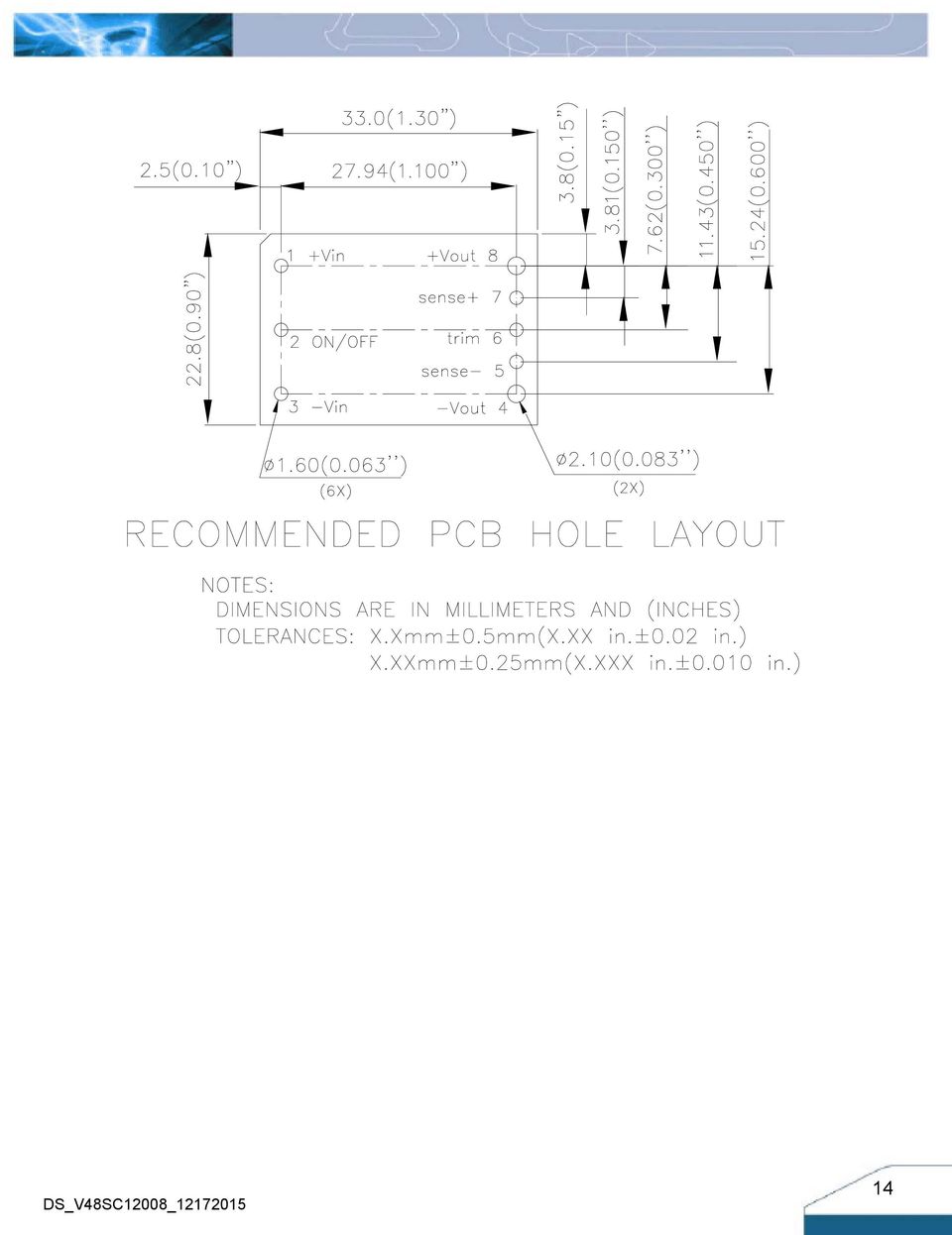
1 Delphi Series V48SC, 1/16th Brick 100W DC/DC Power Modules: 48V in, 12V, 8.3A out The Delphi Series V48SC, 1/16 th Brick, 48V input, single output, isolated DC/DC converters, are the latest offering from a world leader in power systems technology and manufacturing Delta Electronics, Inc. This product family provides up to 100 watts of power or 30A of output current in the 1/16 th brick form factor (1.3 x0.90 ) and pinout. With creative design technology and optimization of component placement, these converters possess outstanding electrical and thermal performance, as well as extremely high reliability under highly stressful operating conditions. Typical efficiency of the 12V/8.3A module is greater than 92.0%. All modules are protected from abnormal input/output voltage, current, and temperature conditions. For lower power needs, but in a similar small form factor, please check out Delta V36SE (50W), S48SP (36W or 10A) and S36SE (17W or 5A) series standard DC/DC modules. FEATURES High efficiency: 12V/8.3A Size: Without heat spreader: 33.0x22.8x9.5mm (1.30 x0.90 x0.37 ) With heat spreader 33.0x22.8x12.7mm (1.30 x0.90 x0.50 ) Industry standard footprint and pinout Fixed frequency operation SMD or through-hole versions Input UVLO OTP and output OCP, OVP Output voltage trim: -20%, +10% Monotonic startup into normal and pre-biased loads 1500V isolation and basic insulation No minimum load required No negative current during power or enable on/off ISO 9001, TL 9000, ISO 14001, QS 9000, OHSAS18001 certified manufacturing facility UL/cUL (US & Canada) OPTIONS SMD pins Short pin lengths available Positive remote On/Off Open frame with heat-spreader APPLICATIONS Optical Transport Data Networking Communications Servers

2 TECHNICAL SPECIFICATIONS (T A=25 C, airflow rate=300 LFM, V in=48vdc, nominal Vout unless otherwise noted.) PARAMETER NOTES and CONDITIONS V48SC12008 (Standard) Min. Typ. Max. Units ABSOLUTE MAXIMUM RATINGS Input Voltage Continuous 80 Vdc Transient (100ms) 100ms 100 Vdc Operating Ambient Temperature C Storage Temperature C Input/Output Isolation Voltage 1500 Vdc INPUT CHARACTERISTICS Operating Input Voltage Vdc Input Under-Voltage Lockout Turn-On Voltage Threshold Vdc Turn-Off Voltage Threshold Vdc Lockout Hysteresis Voltage Vdc Maximum Input Current 100% Load, 36Vin 4 A No-Load Input Current 60 ma Off Converter Input Current 8 12 ma Inrush Current (I 2 t) With 100uF external input capacitor 1 A 2 s Input Reflected-Ripple Current P-P thru 12µH inductor, 5Hz to 20MHz 20 ma Input Voltage Ripple Rejection 120 Hz -60 db OUTPUT CHARACTERISTICS Output Voltage Set Point Vin=48V, Io=Io.max, Tc=25 C Vdc Output Voltage Regulation Over Load Io=Io, min to Io, max ±5 ±12 mv Over Line Vin=36V to 75V ±5 ±12 mv Over Temperature Tc=-40 C to125 C ±180 mv Total Output Voltage Range Over sample load, line and temperature V Output Voltage Ripple and Noise 5Hz to 20MHz bandwidth Peak-to-Peak max load on output, 20MHz bandwidth 10uF tantalum + 1uF ceramic capacitor 100 mv RMS max load on output, 20MHz bandwidth 10uF tantalum + 1uF ceramic capacitor 30 mv Operating Output Current Range A Output Over Current Protection Output Voltage 10% Low % DYNAMIC CHARACTERISTICS Output Voltage Current Transient load capacitor10uf tantalum + 1u ceramic 0.1A/uS Frequency= 250Hz Positive Step Change in Output Current 50% Io.max to 75% Io.max 300 mv Negative Step Change in Output Current 75% Io.max to 50% Io.max 300 mv Settling Time (within 1% Vout nominal) 200 us Turn-On Transient Start-Up Delay Time, From On/Off Control or Input From On/Off Control or Input to 10%Vo 15 ms Start-Up Rise Time, From On/Off Control or Input From 10%Vo to 90% Vo 40 ms Maximum Output Capacitance Full load; 5% overshoot of Vout at startup; µf EFFICIENCY 100% Load Vin=48V 92.0 % 60% Load Vin=48V 92.0 % ISOLATION CHARACTERISTICS Input to Output 1500 Vdc Isolation Resistance 10 MΩ Isolation Capacitance 1000 pf FEATURE CHARACTERISTICS Switching Frequency 420 khz ON/OFF Control, Negative Remote On/Off logic Logic Low (Module On) Von/off V Logic High (Module Off) Von/off V ON/OFF Control, Positive Remote On/Off logic Logic Low (Module Off) Von/off V Logic High (Module On) Von/off V ON/OFF Current (for both remote on/off logic) Ion/off at Von/off=0.0V 1 ma ON/OFF Current (for both remote on/off logic) Ion/off at Von/off=2.4V ua Leakage Current (for both remote on/off logic) Logic High, Von/off=5V ua Output Voltage Trim Range Max rated current guaranteed at full trim range % Output Voltage Remote Sense Range Max rated current guaranteed at full remote sense range 10 % Output Over-Voltage Protection Over full temp range; % of nominal Vout % GENERAL SPECIFICATIONS MTBF Per Telecordia SR-332, 80% load, 25 C, 48Vin, 300LFM 4.9 M hours Weight Open frame 15 grams weight With heat-spreader 24 grams Over-Temperature Shutdown (Open Frame) Refer to Figure 22 for Hot spot1 location (48Vin,80%Io, 200LFM,Airflow from Vout+ to Vin+) 132 C Over-Temperature Shutdown (With Heat Spreader) Refer to Figure 24 for Hot spot2 location (48Vin,80%Io, 200LFM,Airflow from Vout+ to Vin+) 120 C Over-Temperature Shutdown (NTC Resistor) Refer to Figure 22 for NTC resistor location 125 C Note: Please attach thermocouple on NTC resistor to test OTP function, the hot spot s temperature is just for reference. 2

3 ELECTRICAL CHARACTERISTICS CURVES Figure 1: Efficiency vs. load current for minimum, nominal, and maximum input voltage at 25 C Figure 2: Power dissipation vs. load current for minimum, nominal, and maximum input voltage at 25 C. Figure 3: Typical full load input characteristics at room temperature 3

4 ELECTRICAL CHARACTERISTICS CURVES For Negative Remote On/Off Start up Figure 4: Turn-on transient at full rated load current (10 ms/div). Vin=48V. Top Trace: Vout, 5.0V/div; Bottom Trace: ON/OFF input, 5V/div For Input Voltage Start up Figure 5: Turn-on transient at zero load current (10 ms/div). Vin=48V. Top Trace: Vout: 5.0V/div, Bottom Trace: ON/OFF input, 5V/div Figure 6: Turn-on transient at full rated load current (10 ms/div). Vin=48V. Top Trace: Vout, 5.0V/div; Bottom Trace: Vin, 50V/div Figure 7: Turn-on transient at zero load current (10 ms/div). Vin=48V. Top Trace: Vout, 5.0V/div; Bottom Trace: Vin, 50V/div Figure 8: Output voltage response to step-change in load current (75%-50%-75% of Io, max; di/dt = 0.1A/µs). Load cap: 10µF tantalum capacitor and 1µF ceramic capacitor. Top Trace: Vout (0.15V/div, 200us/div), Bottom Trace: Iout (5A/div). Scope measurement should be made using a BNC cable (length shorter than 20 inches). Position the load between 51 mm to 76 mm (2 inches to 3 inches) from the module 4
. Vin=48V. Top Trace: Vout, 5.")
5 ELECTRICAL CHARACTERISTICS CURVES Vin- is ic + + Vin+ Cs: 220uF 100uF, ESR= o C 100KHz Figure 9: Test set-up diagram showing measurement points for Input Terminal Ripple Current and Input Reflected Ripple Current. Note: Measured input reflected-ripple current with a simulated source Inductance (L TEST) of 12 μh. Capacitor Cs offset possible battery impedance. Measure current as shown above Figure 10: Input Terminal Ripple Current, i c, at full rated output current and nominal input voltage with 12µH source impedance and 33µF electrolytic capacitor (200 ma/div, 1us/div) Vo(+) Copper Strip 10u 1u SCOPE RESISTIVE LOAD Vo(-) Figure 11: Input reflected ripple current, i s, through a 12µH source inductor at nominal input voltage and rated load current (20 ma/div, 2us/div) Figure 12: Output voltage noise and ripple measurement test setup Figure 13: Output voltage ripple at nominal input voltage and rated load current (Io=7.5A)(50 mv/div, 1us/div) Load capacitance: 1µF ceramic capacitor and 10µF tantalum capacitor. Bandwidth: 20 MHz. Scope measurements should be made using a BNC cable (length shorter than 20 inches). Position the load between 51 mm to 76 mm (2 inches to 3 inches) from the module. 5

6 DESIGN CONSIDERATIONS Input Source Impedance The impedance of the input source connecting to the DC/DC power modules will interact with the modules and affect the stability. A low ac-impedance input source is recommended. If the source inductance is more than a few μh, we advise adding a 100 μf electrolytic capacitor (ESR < 0.7 Ω at 100 khz) mounted close to the input of the module to improve the stability. Layout and EMC Considerations Delta s DC/DC power modules are designed to operate in a wide variety of systems and applications. For design assistance with EMC compliance and related PWB layout issues, please contact Delta s technical support team. An external input filter module is available for easier EMC compliance design. Below is the reference design for an input filter tested with V48SC120XXX to meet EN55022 (VDE0878) class A(both q. peak and average) Figure 15 - EMI test negative line Schematic and Components List Figure 16 - EMI test positive line Safety Considerations Figure 14 - EMI test schematic C1= 3.3uF/100 V C2= 47uF/100 V C3= 47uF/100 V C4=C5=1nF/250Volt T1=1mH, type P53910(Pulse) Test Result: At T = +25C, Vin = 48 V and full load. Yellow line is quasi peak mode; Blue line is average mode. The power module must be installed in compliance with the spacing and separation requirements of the end-user s safety agency standard, i.e., UL , CSA C22.2 NO nd and IEC nd : 2005 and EN nd: 2006+A11+A1: 2010, if the system in which the power module is to be used must meet safety agency requirements. Basic insulation based on 75 Vdc input is provided between the input and output of the module for the purpose of applying insulation requirements when the input to this DC-to-DC converter is identified as TNV-2 or SELV. An additional evaluation is needed if the source is other than TNV-2 or SELV. When the input source is SELV circuit, the power module meets SELV (safety extra-low voltage) requirements. If the input source is a hazardous voltage which is greater than 60 Vdc and less than or equal to 75 Vdc, for the module s output to meet SELV requirements, all of the following must be met: 6

7 The input source must be insulated from the ac mains by reinforced or double insulation. The input terminals of the module are not operator accessible. A SELV reliability test is conducted on the system where the module is used, in combination with the module, to ensure that under a single fault, hazardous voltage does not appear at the module s output. When installed into a Class II equipment (without grounding), spacing consideration should be given to the end-use installation, as the spacing between the module and mounting surface have not been evaluated. The power module has extra-low voltage (ELV) outputs when all inputs are ELV. This power module is not internally fused. To achieve optimum safety and system protection, an input line fuse is highly recommended. The safety agencies require a Fast-acting fuse with 20A maximum rating to be installed in the ungrounded lead. A lower rated fuse can be used based on the maximum inrush transient energy and maximum input current. Soldering and Cleaning Considerations Post solder cleaning is usually the final board assembly process before the board or system undergoes electrical testing. Inadequate cleaning and/or drying may lower the reliability of a power module and severely affect the finished circuit board assembly test. Adequate cleaning and/or drying is especially important for un-encapsulated and/or open frame type power modules. For assistance on appropriate soldering and cleaning procedures, please contact Delta s technical support team. Over-Current Protection The modules include an internal output over-current protection circuit, which will endure current limiting for an unlimited duration during output overload. If the output current exceeds the OCP set point, the modules will automatically shut down, and enter hiccup mode or latch mode, which is optional, the default is hiccup mode. For hiccup mode, the module will try to restart after shutdown. If the over current condition still exists, the module will shut down again. This restart trial will continue until the over-current condition is corrected. Over-Voltage Protection The modules include an internal output over-voltage protection circuit, which monitors the voltage on the output terminals. If this voltage exceeds the over-voltage set point, the module will shut down, and enter in hiccup mode or latch mode, which is optional, the default is hiccup mode. For hiccup mode, the module will try to restart after shutdown. If the over voltage condition still exists, the module will shut down again. This restart trial will continue until the over-voltage condition is corrected. For latch mode, the module will latch off once it shutdown. The latch is reset by either cycling the input power or by toggling the on/off signal for one second. Over-Temperature Protection The over-temperature protection consists of circuitry that provides protection from thermal damage. If the temperature exceeds the over-temperature threshold the module will shut down, and enter in auto-restart mode or latch mode, which is optional, the default is auto-restart mode. For auto-restart mode, the module will monitor the module temperature after shutdown. Once the temperature is dropped and within the specification, the module will be auto-restart. Remote On/Off The remote on/off feature on the module can be either negative or positive logic. Negative logic turns the module on during a logic low and off during a logic high. Positive logic turns the modules on during a logic high and off during a logic low. Remote on/off can be controlled by an external switch between the on/off terminal and the Vi(-) terminal. The switch can be an open collector or open drain. For negative logic if the remote on/off feature is not used, please short the on/off pin to Vi(-). For positive logic if the remote on/off feature is not used, please leave the on/off pin floating. Vi(+) ON/OFF Vi(-) Vo(+) Sense(+) Sense(-) Vo(-) Figure 17: Remote on/off implementation Remote Sense Remote sense compensates for voltage drops on the output by sensing the actual output voltage at the point of load. The voltage between the remote sense pins and the output terminals must not exceed the output voltage sense range given here: [Vo(+) Vo( )] [SENSE(+) SENSE( )] 10% Vout This limit includes any increase in voltage due to remote sense compensation and output voltage set point adjustment (trim). 7
, spacing consideration should be given to the end-use installation, as the spacing between the module and mounting surface have not been")
8 FEATURES DESCRIPTIONS (CON.) Vi(+) Vo(+) Sense(+) If the external resistor is connected between the TRIM and SENSE (-) pins, the output voltage set point decreases (Fig. 19). The external resistor value required to obtain a percentage of output voltage change % is defined as: Contact Resistance Vi(-) Sense(-) Vo(-) Contact and Distribution Losses 511 Rtrim down K Ex. When Trim-down -10% (12V 0.9=10.8V) Figure 18: Effective circuit configuration for remote sense operation If the remote sense feature is not used to regulate the output at the point of load, please connect SENSE(+) to Vo(+) and SENSE( ) to Vo( ) at the module. 511 Rtrim down K 40. K The output voltage can be increased by both the remote sense and the trim; however, the maximum increase is the larger of either the remote sense or the trim, not the sum of both. When using remote sense and trim, the output voltage of the module is usually increased, which increases the power output of the module with the same output current. Max rated current is guaranteed at full output voltage remote sense range. Output Voltage Adjustment (TRIM) To increase or decrease the output voltage set point, connect an external resistor between the TRIM pin and SENSE(+) or SENSE(-). The TRIM pin should be left open if this feature is not used. Figure 20: Circuit configuration for trim-up (increase output voltage) If the external resistor is connected between the TRIM and SENSE (+) the output voltage set point increases (Fig. 20). The external resistor value required to obtain a percentage output voltage change % is defined as: 5.11Vo (100 ) 511 Rtrim up K Ex. When Trim-up +10% (12V 1.1=13.2V) (100 10) 511 Rtrim up K Trim resistor can also be connected to Vo+ or Vo- but it would introduce a small error voltage than the desired value. Figure 19: Circuit configuration for trim-down (decrease output voltage) The output voltage can be increased by both the remote sense and the trim, however the maximum increase is the larger of either the remote sense or the trim, not the sum of both. When using remote sense and trim, the output voltage of the module is usually increased, which increases the power output of the module with the same output current. Max rated current is guaranteed at full output voltage trim range. 8
 Figure 18: Effective circuit configuration for remote sense operation If the remote sense feature is not used to regulate the output at the point of load, please connect SENSE(+) to Vo(+) and")
9 THERMAL CONSIDERATIONS THERMAL CURVES (OPEN FRAME) Thermal management is an important part of the system design. To ensure proper, reliable operation, sufficient cooling of the power module is needed over the entire temperature range of the module. Convection cooling is usually the dominant mode of heat transfer. Hence, the choice of equipment to characterize the thermal performance of the power module is a wind tunnel. Thermal Testing Setup HOT SPOT AIRFLOW Delta s DC/DC power modules are characterized in heated vertical wind tunnels that simulate the thermal environments encountered in most electronics equipment. This type of equipment commonly uses vertically mounted circuit cards in cabinet racks in which the power modules are mounted. The following figure shows the wind tunnel characterization setup. The power module is mounted on a test PWB and is vertically positioned within the wind tunnel. The space between the neighboring PWB and the top of the power module is constantly kept at 6.35mm (0.25 ). NTC RESISTOR Figure 22: * Hot spot 1& NTC resistor temperature measurement location. The allowed maximum hot spot temperature is defined at V48SC12008(Standard) Output Power vs. Ambient Temperature and Air Velocity Output Power = 48V (Either Orientation) Natural Convection 100LFM 200LFM 300LFM 40 FANCING PWB PWB LFM MODULE LFM LFM AIR VELOCITY AND AMBIENT TEMPERATURE SURED BELOW THE MODULE AIR FLOW 50.8(2.00") Ambient Temperature ( ) Figure 23: Output Power vs. Ambient Temperature and Air Vin=48V (Either Orientation, Open Frame) Note: Wind Tunnel Test Setup Figure Dimensions are in millimeters and (Inches) Figure 21: Wind tunnel test setup Thermal Derating Heat can be removed by increasing airflow over the module. To enhance system reliability, the power module should always be operated below the maximum operating temperature. If the temperature exceeds the maximum module temperature, reliability of the unit may be affected. 9

10 THERMAL CURVES (WITH HEAT SPREADER) AIRFLOW Figure 24: * Hot spot 2 temperature measurement location. The allowed maximum hot spot temperature is defined at 108 V48SC12008(Standard) Output Current vs. Ambient Temperature and Air Velocity Output Power = 48V (Either Orientation,With Heatspreader) Natural Convection 100LFM LFM 300LFM LFM 500LFM LFM Ambient Temperature ( ) Figure 25: Output Power vs. Ambient Temperature and Air Vin=48V (Either Orientation, with heat spreader) 10
 Figure 25: Output Power vs.")

11 LEADED (Sn/Pb) PROCESS RECOMMEND TEMP. PROFILE Note: The temperature refers to the pin of V48SC, measured on the pin +Vout joint. LEAD FREE (SAC) PROCESS RECOMMEND TEMP. PROFILE Temp. Peak Temp. 240 ~ Ramp down max. 4 /sec Ramp up max. 3 /sec. Preheat time 100~140 sec. Time Limited 90 sec. above 217 Time Note: The temperature refers to the pin of V48SC, measured on the pin +Vout joint. 11

12 MECHANICAL DRAWING Surface-mount module Through-hole module 12

13 Through-hole module with heat spreader For modules with through-hole pins and the optional heatspreader, they are intended for wave soldering assembly onto system boards; please do not subject such modules through reflow temperature profile. All pins are copper alloy with Matte tin over Ni plated. 13

14 14
15 PART NUMBERING SYSTEM V 48 S C N R F A Type of Product Input Voltage Number of Outputs Product Series Output Voltage Output Current ON/OFF Logic Pin Length/Type Option Code V - 1/16 Brick 48-36V~75V S - Single C - Serial number V A N - Negative P - Positive R N K M - SMD F - RoHS 6/6 A - Standard Functions (Lead Free) H - With heat spreader Space- RoHS5/6 MODEL LIST MODEL NAME INPUT OUTPUT 100% LOAD V48SC12008NRFA 36~75V 4A 12V 8.3A 92% V48SC12008NRFH 36~75V 4A 12V 8.3A 92% Default remote on/off logic is negative and pin length is For different remote on/off logic and pin length, please refer to part numbering system above or contact your local sales office. CONTACT: USA: Telephone: East Coast: West Coast: Fax: (978) dcdc@deltaww.com Europe: Phone: Fax: Asia & the rest of world: Telephone: Ext 6220~6224 Fax: WARRANTY Delta offers a two (2) year limited warranty. Complete warranty information is listed on our web site or is available upon request from Delta. Information furnished by Delta is believed to be accurate and reliable. However, no responsibility is assumed by Delta for its use, nor for any infringements of patents or other rights of third parties, which may result from its use. No license is granted by implication or otherwise under any patent or patent rights of Delta. Delta reserves the right to revise these specifications at any time, without notice. 15

Delphi Series V48SC, 1/16th Brick 90W DC/DC Power Modules: 48V in, 12V, 7.5A out
 Delphi Series V48SC, 1/16th Brick 90W DC/DC Power Modules: 48V in, 12V, 7.5A out The Delphi Series V48SC, 1/16 th Brick, 48V input, single output, isolated DC/DC converters, are the latest offering from
Delphi Series V48SH, 1/16 th Brick 35W DC/DC Power Modules: 48V in, 1.0V, 35A out
 Delphi Series V48SH, 1/16 th Brick 35W DC/DC Power Modules: 48V in, 1.0V, 35A out The Delphi Series V48SH, 1/16 th Brick, 48V input, single output, isolated DC/DC converter, is the latest offering from
S24SE/S24DE series 20W Single/Dual Output DC/DC Converter
 FEATURES Efficiency up to 88% Wide input range, 9V-36V Package with Industry Standard Pinout Package Dimension: 25.4 x25.4 x10.2mm (1.0 x1.0 x0.40 )(No HSK) Over voltage protection, hiccup mode Over current
S24SE/S24DE series 10W Single/Dual Output DC/DC Converter
 FEATURES Efficiency up to 87% Wide input range, 9V-36V Package with Industry Standard Pinout Package Dimension: 25.4 x25.4 x10.2mm (1.0 x1.0 x0.40 )(No HSK) Over voltage protection, hiccup mode Over current
Maximum Input Current Vin=18V, 100% Load 12.6 13.1 A
 FEATURES Wide input voltage range, 18~60V 200W Output @ 18V~27V Vin range 300W Output @ 27~60V Vin range (Including 27V) Full Load Efficiency up to 88.3% @48Vin Intergrated fuse holder Parallel Connection
Lockout Hysteresis Voltage 1 2 3 VDC Maximum Input Current Vin=18V, 100% Load 13.0 13.5 A Vin=24V 180 220 ma
 FEATURES Ultra wide input voltage range, 18~106V 200W Output @ 18V~27V Vin range 300W Output @ 27~106V Vin range (Including 27V) Full Load Efficiency up to 91.0% @48Vin Intergrated fuse holder Parallel
Application Note TMA Series
 1W, SIP, Single & Dual Output DC/DC Converters Features SIP Package with Industry Standard Pinout Package Dimension: 19.5 x 10.2 x 6.1 mm (0.77 x 0.4 x 0.24 ) 5V&12V Models 19.5 x 10.2 x 7.1 mm (0.77 x
DC/DC Converter 9 to 18Vdc and 18 to 36Vdc and 36 to 75Vdc input, 20 Watt Output Power; 3.3 to 15Vdc Single Output and ±12Vdc to ±15Vdc Dual Output
 THN 20 Series Application Note DC/DC Converter 9 to 18Vdc and 18 to 36Vdc and 36 to 75Vdc input, 20 Watt Output Power; 3.3 to 15Vdc Single Output and ±12Vdc to ±15Vdc Dual Output Pending Applications Wireless
SELECTION GUIDE. Nominal Input
 www.murata-ps.com NKE Series FEATURES RoHS Compliant Sub-Miniature SIP & DIP Styles 3kVDC Isolation UL Recognised Wide Temperature performance at full 1 Watt load, 40 C to 85 C Increased Power Density
LDO03C/LDO06C/LDO10C
 NEW LDO03C/LDO06C/LDO10C A p p l i c a t i o n N o t e 1 8 6 1. Introduction 2 2. Models Features 2 3. General Description Electrical Description 2 Physical Construction 2 4. Features and Functions Wide
CMR Series Isolated 0.75W Single and Dual Output Isolated DC/DC Converters
 www.murata-ps.com CMR Series SELECTION GUIDE FEATURES Single or Dual Isolated Outputs 1kVDC or 3kVDC options Wide temperature performance at full 0.75W load -40 C to 85C Industry Standard Pinouts 5V, 12V
Limited Ericsson Internal
 Limited TABLE PRODUCT OF CONTENTS SPECIFICATION 1 (1) (3) SEC/D Kevin Chen 152-EN/LZT146311 1/131-BMR632 Technical Uen Specification PKL 4 PI series 26-12-4 27-1-11 B D DC/DC converters, Input 36-, Output
DC/DC power modules basics
 DC/DC power modules basics Design Note 024 Ericsson Power Modules General Abstract This design note covers basic considerations for the use of on-board switch mode DC/DC power modules, also commonly known
AVD75-48S1V2. Product Descriptions. Applications. 30 Watts
 30 Watts Sixteenthbrick Converter Page 1 Total Power: 30 Watts Input Voltage: 36 to 75 Vdc # of Outputs: Single Special Features Delivers up to 25A output Ultrahigh efficiency 87% typ. at half load and
TEP 200WIR Series, 180 240 Watt
 TEP 200WIR Series, 180 240 Watt Features Chassis mount with screw terminal block Including EMI filter to meet EN 55022, class A Ultra wide 4:1 input voltage ranges 8.5 36, 16.5 75, 43 160 VDC EN 50155
AVD120-48S12. Product Descriptions. Applications. 120 Watts
 120 Watts Sixthteenthbrick Converter Page 1 Total Power: 120 Watts Input Voltage: 36 to 75 Vdc # of Outputs: Single Special Features Delivering up to 10A output Ultrahigh efficiency 93% typ. at full load
www.murata-ps.com D1U54P-W-1200-12-HxxC Series 54mm 1U Front End AC-DC Power Supply Converter www.murata-ps.com/support PRODUCT OVERVIEW FEATURES
 www.murata-ps.com PRODUCT OVERVIEW D1U54P-W-1200-12-HxxC Series The D1U54P-W-1200-12-HxxC series are 80 PLUS Platinum effi ciency 1200 watt, power factor corrected front end supplies with a 12V main output
LDS8720. 184 WLED Matrix Driver with Boost Converter FEATURES APPLICATION DESCRIPTION TYPICAL APPLICATION CIRCUIT
 184 WLED Matrix Driver with Boost Converter FEATURES High efficiency boost converter with the input voltage range from 2.7 to 5.5 V No external Schottky Required (Internal synchronous rectifier) 250 mv
UMEC International Corporation
 UP1301A SERIES 130 Watt Open Frame Switchers Small Size 3*5*1.2(inches) Universal Input to 264 VAC Low Power Consumption Overvoltage Protection Continuous Short Circuit Protection Over Temperature Protection
AC/DC Power Modules C B. TML Series, 20 & 40 Watt. Features. 20 Watt Models
 TML Series, 0 & 0 Watt Features C B Scheme LVD UL 090- Encapsulated power supplies with increased power density Replaces TML and TML 0 series PCB mount or chassis mount with screw terminals Single, dual
Silvertel. Ag5200. 1 Features. 2 Description. Power-over-Ethernet Plus Module. IEEE802.3at and IEEE802.3af compliant. Maximum 30W output power
 Silvertel V1.1 November 2012 Datasheet Pb 1 Features IEEE802.3at and IEEE802.3af compliant Maximum 30W output power Dual In-Line (DIL) package size 50.6mm (L) x 30mm (W) Overload, short-circuit and thermal
Cool-Power PI33xx-x0. 8 V to 36 V IN Cool-Power ZVS Buck Regulator Family. Product Description. Features & Benefits. Applications. Package Information
 Cool-Power PI33xx-x0 8 V to 36 V IN Cool-Power ZVS Buck Regulator Family Product Description The PI33xx-x0 is a family of high efficiency, wide input range DC-DC ZVS-Buck regulators integrating controller,
Series AMLDL-Z Up to 1000mA LED Driver
 FEATURES: Click on Series name for product info on aimtec.com Series Up to ma LED Driver Models Single output Model Input Voltage (V) Step Down DC/DC LED driver Operating Temperature range 4ºC to 85ºC
APD336.221/.421 3 Outputs 19" DC/DC Converter, 50 Watt
 APD336.221/.421 3 Outputs 19" DC/DC Converter, 50 Watt High efficiency: 79% (@ 48V) DCin wide range: 9...36V or 18...72V DC 8 HP plug in width H15 standard pinout Active inrush current suppression Voltage
OKI-78SR Series Fixed Output 1.5 Amp SIP DC/DC Converters
 OKI-78SR Series Typical unit FEATURES Ultra wide 7 to 36 VDC input range Fixed Outputs of 3.3 or 5 VDC up to 1.5 Amps Vertical SIP-mount, small footprint package No heat sink direct replacement for 3-terminal
28 Volt Input - 40 Watt
 Features Powers 28 volt dc-dc converters during power dropout Input voltage 12 to 40 volts Operating temperature -55 to +125 C Reduces hold-up capacitance by 80% Inhibit function Synchronization function
28 V, 56 m, Load Switch with Programmable Current Limit and Slew Rate Control
 28 V, 56 m, Load Switch with Programmable Current Limit and Slew Rate Control OPERATION DESCRIPTION SiP32419 and SiP32429 are load switches that integrate multiple control features that simplify the design
DC-DC Converter Module
 45 Features DC input range: 250-425V Input surge withstand: 500V for 100ms DC output: 24V Programmable output: 10 to 110% Regulation: ±0.2% no load to full load Efficiency: 88% Maximum operating temperature:
LM2704 Micropower Step-up DC/DC Converter with 550mA Peak Current Limit
 Micropower Step-up DC/DC Converter with 550mA Peak Current Limit General Description The LM2704 is a micropower step-up DC/DC in a small 5-lead SOT-23 package. A current limited, fixed off-time control
LM1084 5A Low Dropout Positive Regulators
 5A Low Dropout Positive Regulators General Description The LM1084 is a series of low dropout voltage positive regulators with a maximum dropout of 1.5 at 5A of load current. It has the same pin-out as
STRATO LED Drivers 70W, Single output
 Features STRATO switch mode driver technology is designed to generate one constant current output from a wide range AC input. The size and performance of these products make them the ideal choice for LED
Instruction Manual PFE300S 500S SERIES. TDK-Lambda PFE300S 500S Series INSTRUCTION MANUAL
 PFE300S 500S SERIES Instruction Manual TDK-Lambda PFE300S 500S Series BEFORE USING THE POWER SUPPLY UNIT Be sure to read this instruction manual thoroughly before using this product. Pay attention to all
AN-8019 Reliable USB Modem Design Using the Combination of an Integrated Load Switch and a Buck Converter
 www.fairchildsemi.com AN-8019 Reliable USB Modem Design Using the Combination of an Integrated Load Switch and a Buck Converter Introduction In the portable electronics market, a wireless network allows
Antec TruePower User's Manual
 User s Manual Antec TruePower User's Manual Antec TruePower ATX12V power supply Models: TRUE330, TRUE380, TRUE430, TRUE480, TRUE550 Antec Low Noise Technology: The Antec TruePower power supply is equipped
Electrical Specification. PKY 2000 PI series DC/DC converters, Input 18-36 V, Output 21.5 A/600 W Ericsson Power Modules AB
 PRODUCT TABLE OF CONTENTS SPECIFICATION 1 (1) (4) SEC/S Kevin Zhou 1/1301-BMR 00152-EN/LZT146385 638/2 Technical Uen Uen Specification PKY 2000 PI series 2011-02-24 2011-03-09 E C Key Features Full-brick
650W Single Output Power Supply 15V 24V. 27V 48V Rated Current. 0 ~ 100A 0 ~ 50A 0 ~ 40A 0 ~ 27A 0 ~ 24A 0 ~ 13.6A Rated Power
 Features: Universal AC input / Full range Programmable output Voltage (0% ~ 05%) Programmable output Current (% ~ 05%) + / 0.5A auxiliary output Forced current sharing at parallel operation Power OK signal
O WA-120U series IP67. 120W Single Output Switching Power Supply. Features. Aplications
 Features UniversalACinput/Fulrange Built-inactivePFCfunction Higheficiencyupto91% Protections:Shortcircuit/Overcurent/ Overvoltage/Overtemperature Fanlesdesign,colingbyfreairconvection Colingbyfreairconvection
Advanced Monolithic Systems
 Advanced Monolithic Systems FEATURES Three Terminal Adjustable or Fixed oltages* 1.5, 1.8, 2.5, 2.85, 3.3 and 5. Output Current of 1A Operates Down to 1 Dropout Line Regulation:.2% Max. Load Regulation:.4%
OKR-T/30-W12-C Adjustable Output 30-Amp SIP-mount DC-DC Converters
 www.murata-ps.com OKR-T/30-W12-C Typical unit FEATURES 700 KHz operation 5.5-13.8 Vdc input voltage range Programmable output voltage from 0.591-6.0 VDC High power conversion effi ciency at 95% Outstanding
OKY-T/3,T/5-D12 Series Adjustable Output 3 and 5-Amp DOSA-SMT DC/DC Converters
 www.murata-ps.com Typical unit PRODUCT OVERVIEW The OKY-T/3 and -T/5 series are miniature non-isolated Point-of-Load (POL) DC/DC power converters for embedded applications. The module is fully compatible
650W Single Output Power Supply
 AK-650 series Features : Universal AC input with active PFC Programmable output Voltage ( 0% ~ 05% ) Programmable output Current ( % ~ 05% ) High efficiency up to 9% + / 0.5A auxiliary output Intelligent
MP2259 1A, 16V, 1.4MHz Step-Down Converter
 MP59 1A, 1V, 1.MHz Step-Down Converter TM The Future of Analog IC Technology DESCRIPTION The MP59 is a monolithic integrated stepdown switch mode converter with an internal power MOSFET. It achieves 1A
FAN5346 Series Boost LED Driver with PWM Dimming Interface
 FAN5346 Series Boost LED Driver with PWM Dimming Interface Features Asynchronous Boost Converter Drives LEDs in Series: FAN5346S20X: 20V Output FAN5346S30X: 30V Output 2.5V to 5.5V Input Voltage Range
1000W Single Output Power Supply 15V 24V. Protection type: Total Power limit, Latch-style (Recovery after reset AC power ON or inhibit)
") 000W Single Output Power Supply AK-000 series Features: Universal AC input / Full range Programmable output Voltage (0% ~ 05%) Programmable output Current (% ~ 05%) + / 0.5A auxiliary output U profile,
000W Single Output Power Supply AK-000 series Features: Universal AC input / Full range Programmable output Voltage (0% ~ 05%) Programmable output Current (% ~ 05%) + / 0.5A auxiliary output U profile,
S112-XHS. Description. Features. Agency Approvals. Applications. Absolute Maximum Ratings. Schematic Diagram. Ordering Information
 Description Features The S112-X is a bi-directional, single-pole, single-throw, normally open multipurpose solid-state relay. The circuit is composed of one input IR LED with a series limiting resistor
Product Family of Capacitor Chargers PS-17XX for 1500J/Sec in the range 500Vac to 1,000Vac PS-22XX for 2200J/Sec in the range 500Vac to 1,000Vac
 Product Description Capacitor charger power supplies from Digital Power are designed to meet the exacting requirements of medical, aesthetic, and industrial pulsed energy systems. The modular design of
UL/ RAILWAYS Certified Constant Current LED Driver Wide Input and Output Voltage Range Digital PWM and Analogue Voltage Dimming
 Features Regulated Converters Selection Guide UL/ RAILWAYS Certified Constant Current LED Driver Wide Input and Output Voltage Range Digital PWM and Analogue Voltage Dimming Short Circuit Protected Pinned
AS2815. 1.5A Low Dropout Voltage Regulator Adjustable & Fixed Output, Fast Response
 1.5A Low Dropout oltage Regulator Adjustable & Fixed Output, Fast Response FEATURES Adjustable Output Down To 1.2 Fixed Output oltages 1.5, 2.5, 3.3, 5.0 Output Current of 1.5A Low Dropout oltage 1.1 Typ.
LM138 LM338 5-Amp Adjustable Regulators
 LM138 LM338 5-Amp Adjustable Regulators General Description The LM138 series of adjustable 3-terminal positive voltage regulators is capable of supplying in excess of 5A over a 1 2V to 32V output range
DC/DC converter Input 36-72 Vdc Output up to 15A/60W
 PKG 4000 I DC/DC converter Input 36-72 Vdc Output up to 15A/60W Size 74.7x63.5x11.0 mm (2.94x2.50x0.433 in.) Efficiency typ 86% (5 V) at full load 1500 Vdc isolation voltage MTBF >200 years at +75 C case
ICS650-44 SPREAD SPECTRUM CLOCK SYNTHESIZER. Description. Features. Block Diagram DATASHEET
 DATASHEET ICS650-44 Description The ICS650-44 is a spread spectrum clock synthesizer intended for video projector and digital TV applications. It generates three copies of an EMI optimized 50 MHz clock
Electrical Specification. PKY 4000 PI series DC/DC converters, Input 36-75 V, Output up to 25 A/700 W Ericsson Power Modules AB
 PRODUCT TABLE OF CONTENTS SPECIFICATION 1 (1) (4) SEC/S Kevin Zhou 1/1301-BMR 00152-EN/LZT146380 638/2 Technical Uen Uen Specification PKY 4000 PI series 2011-02-24 2011-03-09 E D Key Features Full-brick
Silvertel. Ag9800M. 1. Features. 2. Description. Miniature PoE Module. Small SMT package. IEEE802.3af compliant. Low cost
 Silvertel V1.2 December 2014 Datasheet Ag9800M Miniature PoE Module Pb 1. Features Small SMT package IEEE802.3af compliant Low cost Input voltage range 36V to 57V Minimal external components required Short-circuit
EPL225 Series. 225 Watts. www.xppower.com. AC-DC Power Supplies. Models & Ratings. Summary
 225 Watts 50 W Convection/ 225 W Forced-cooled Ratings 2 by 4 Footprint Low.26 Profile 2 V Fan Output High Efficiency, up to 95% ITE & Medical pprovals High Power Density Less than 0.5 W No Load Input
LM2941/LM2941C 1A Low Dropout Adjustable Regulator
 LM2941/LM2941C 1A Low Dropout Adjustable Regulator General Description The LM2941 positive voltage regulator features the ability to source 1A of output current with a typical dropout voltage of 0.5V and
R-78xx-0.5 INNOLINE. Features. 0.5 AMP SIP3 Single Output. Derating-Graph (Ambient Temperature) DC/DC-Converter
 DC/DC-Converter") Features Description Efficiency up to 97%,Non isolated, no need for heatsinks Pin-out compatible with LM78XX Linears Very low profile( L*W*H=11.5*7.5*10.2 ) Wide input range.(4.75v ~ 32V) Short circuit
Features Description Efficiency up to 97%,Non isolated, no need for heatsinks Pin-out compatible with LM78XX Linears Very low profile( L*W*H=11.5*7.5*10.2 ) Wide input range.(4.75v ~ 32V) Short circuit
OKI-78SR Series Fixed Output 1.5 Amp SIP DC/DC Converters
 www.murata-ps.com OKI-78SR Series Typical units FEATURES Ultra wide 7 to 36 VDC input range Fixed Outputs of 3.3 or 5 VDC up to 1.5 Amps Vertical or horizontal SIP-mount, small footprint package No heat
OKR-T/30-W12-1C Adjustable Output 30-Amp SIP-mount DC-DC Converters
 www.murata-ps.com OKR-T/30-W12-1C Typical unit FEATURES 700 KHz operation 5.5-13.8 Vdc input voltage range Programmable output voltage from 0.591-6.0 VDC High power conversion effi ciency at 95% Outstanding
* Requires external power line filter and hold up capacitors; see typical applica on circuit and app notes for details
 The 8500 module contains all of the necessary circuitry for complete power line compliance with aeronau cs specifica on RTCA/DO 60G and Boeing's D6 36440(C)*. It is a pin for pin and form fit compa ble
Chrome DIN Rail Power Supply 12V 54W 1 Phase (Class II & NEC Class 2) / DRC-12V60W1AG
 / DRC-12V60W1AG") Highlights & Features Protection Class II, Double Isolation (No Earth connection is required) Universal AC input voltage and full power up to 55 C Power will not de-rate for the entire input voltage range
Highlights & Features Protection Class II, Double Isolation (No Earth connection is required) Universal AC input voltage and full power up to 55 C Power will not de-rate for the entire input voltage range
LM117 LM317A LM317 3-Terminal Adjustable Regulator
 LM117 LM317A LM317 3-Terminal Adjustable Regulator General Description The LM117 series of adjustable 3-terminal positive voltage regulators is capable of supplying in excess of 1 5A over a 1 2V to 37V
29V High Voltage LED Driver
 29V High Voltage LED Driver SP7601 FEATURES Wide Input Voltage Range 4.5V 29V 1.2MHz Constant Frequency Operation Low 0.2V Reference Voltage Adjustable Overcurrent Protection PWM Dimming and Power sequencing
Chrome DIN Rail Power Supply 24V 30W 1 Phase (Class II & NEC Class 2) / DRC-24V30W1AZ
 / DRC-24V30W1AZ") Highlights & Features Protection Class II, Double Isolation (No Earth connection is required) Universal AC input voltage without power de-rating Efficiency > 87.0% @ 115Vac & 230Vac NEC Class 2 / Limited
Highlights & Features Protection Class II, Double Isolation (No Earth connection is required) Universal AC input voltage without power de-rating Efficiency > 87.0% @ 115Vac & 230Vac NEC Class 2 / Limited
Features. Applications. Truth Table. Close
 ASSR-8, ASSR-9 and ASSR-8 Form A, Solid State Relay (Photo MOSFET) (0V/0.A/0Ω) Data Sheet Description The ASSR-XX Series consists of an AlGaAs infrared light-emitting diode (LED) input stage optically
Simple PWM Boost Converter with I/O Disconnect Solves Malfunctions Caused when V OUT <V IN
 Simple PWM Boost Converter with I/O Disconnect Solves Malfunctions Caused when V OUT
MP2456 0.5A, 50V, 1.2MHz Step-Down Converter in a TSOT23-6
 MP2456 0.5A, 50V, 1.2MHz Step-Down Converter in a TSOT23-6 DESCRIPTION The MP2456 is a monolithic, step-down, switchmode converter with a built-in power MOSFET. It achieves a 0.5A peak-output current over
AAT1150 1MHz 1A Step-Down DC/DC Converter
 General Description Features SwitchReg The AAT115 SwitchReg is a step-down switching converter ideal for applications where high efficiency, small size, and low ripple are critical. Able to deliver 1A
Datasheet. 2A 380KHZ 20V PWM Buck DC/DC Converter. Features
 General Description Features The is a 380 KHz fixed frequency monolithic step down switch mode regulator with a built in internal Power MOSFET. It achieves 2A continuous output current over a wide input
SC728/SC729. 2A Low Vin, Very Low Ron Load Switch. POWER MANAGEMENT Features. Description. Applications. Typical Application Circuit SC728 / SC729
 POWER MANAGEMT Features Input Voltage Range 1.1V to 2A Continuous Output Current Ultra-Low Ron 36mΩ Automatic Output Discharge Circuit Fast Turn-on Option With No Output Discharge Circuit SC728 Extended
Single Output Switching Power Supply
 .. RS- Code: CLP-A Single Output Switching Power Supply SPECIFICATION MODEL OUTPUT INPUT PROTECTION ENVIRONMENT SAFETY EMC (Note 6) OTHERS NOTE DC VOLTAGE RATED CURRENT CURRENT RANGE RATED POWER RIPPLE
IS31LT3360 40V/1.2A LED DRIVER WITH INTERNAL SWITCH. January 2014
 40V/1.2A LED DRIVER WITH INTERNAL SWITCH January 2014 GENERAL DESCRIPTION The IS31LT3360 is a continuous mode inductive step-down converter, designed for driving a single LED or multiple series connected
7.5 Watt AC-DC Switch Power Supply
 MAIN FEATURES: 7.5W Small Compact Size PCB Mount Single Output Regulated Output Range : 3.3VDC 24VDC Input Range : 85VAC 265VAC/47 63Hz Or 120VDC 370VDC Very Low Standby Power Consumption < 0.15W Better
FPAB20BH60B PFC SPM 3 Series for Single-Phase Boost PFC
 FPAB20BH60B PFC SPM 3 Series for Single-Phase Boost PFC Features UL Certified No. E209204 (UL1557) 600 V - 20 A Single-Phase Boost PFC with Integral Gate Driver and Protection Very Low Thermal Resistance
Kit 27. 1W TDA7052 POWER AMPLIFIER
 Kit 27. 1W TDA7052 POWER AMPLIFIER This is a 1 watt mono amplifier Kit module using the TDA7052 from Philips. (Note, no suffix.) It is designed to be used as a building block in other projects where a
RoHS APPROVAL SHEET. ituner 12V/6.6A SERIES NO. (E17) EA10953A. ( ) Edac Power Electronics (Suzhou) Co., Ltd. 59 No.59, Chang Sheng Road, Sheng Pu,
 EA10953A. ( ) Edac Power Electronics (Suzhou) Co., Ltd. 59 No.59, Chang Sheng Road, Sheng Pu,") APPROVAL SHEET CUSTOMER ituner CUSTOMER P/N DESCRIPTION EDAC MODEL 12V/6.6A SERIES NO. (E17) EA10953A DATE 2010-06-22 REVISION 0 APPROVED DESIGN PREPARE RoHS CONCLUSION APPROVED CONDITON CUSTOMER S APP
APPROVAL SHEET CUSTOMER ituner CUSTOMER P/N DESCRIPTION EDAC MODEL 12V/6.6A SERIES NO. (E17) EA10953A DATE 2010-06-22 REVISION 0 APPROVED DESIGN PREPARE RoHS CONCLUSION APPROVED CONDITON CUSTOMER S APP
LM3940 1A Low Dropout Regulator for 5V to 3.3V Conversion
 1A Low Dropout Regulator for 5V to 3.3V Conversion General Description The LM3940 is a 1A low dropout regulator designed to provide 3.3V from a 5V supply. The LM3940 is ideally suited for systems which
OKR-T/1.5-W12-C Adjustable Output 1.5-Amp SIP-mount DC/DC Converters
 www.murata-ps.com OKR-T/1.5-W12-C Typical unit FEATURES 600 KHz operation 4.5-14 Vdc input voltage range Programmable output voltage from 0.591-6.0 VDC High power conversion effi ciency at 93% Outstanding
SG2525A SG3525A REGULATING PULSE WIDTH MODULATORS
 SG2525A SG3525A REGULATING PULSE WIDTH MODULATORS 8 TO 35 V OPERATION 5.1 V REFERENCE TRIMMED TO ± 1 % 100 Hz TO 500 KHz OSCILLATOR RANGE SEPARATE OSCILLATOR SYNC TERMINAL ADJUSTABLE DEADTIME CONTROL INTERNAL
30V Internal Switch LCD Bias Supply
 19-1666; Rev 1; 1/3 3V Internal Switch LCD Bias Supply General Description The boost converter contains a.5a internal switch in a tiny 6-pin SOT23 package. The IC operates from a +2.4V to +5.5V supply
AAT4280 Slew Rate Controlled Load Switch
 General Description Features SmartSwitch The AAT4280 SmartSwitch is a P-channel MOSFET power switch designed for high-side load switching applications. The P-channel MOSFET device has a typical R DS(ON)
PowerAmp Design. PowerAmp Design PAD135 COMPACT HIGH VOLATGE OP AMP
 PowerAmp Design COMPACT HIGH VOLTAGE OP AMP Rev G KEY FEATURES LOW COST SMALL SIZE 40mm SQUARE HIGH VOLTAGE 200 VOLTS HIGH OUTPUT CURRENT 10A PEAK 40 WATT DISSIPATION CAPABILITY 200V/µS SLEW RATE APPLICATIONS
OKR-T/10-W12 Series Adjustable Output 10-Amp SIP-mount DC/DC Converters
 www.murata-ps.com OKR-T/10-W12 Series Typical unit FEATURES 600 KHz operation 4.5-14 Vdc input voltage range Programmable output voltage from 0.591-6.0 VDC Drives up to 200 μf ceramic capacitive loads
Chrome DIN Rail Power Supply 24V 91.2W 1 Phase (Class II & NEC Class 2) / DRC-24V100W1AZ
 / DRC-24V100W1AZ") Highlights & Features Protection Class II, Double Isolation (No Earth connection is required) Universal AC input voltage without power de-rating Efficiency > 87.0% @ 115Vac, > 89.0% @ 230Vac NEC Class
Highlights & Features Protection Class II, Double Isolation (No Earth connection is required) Universal AC input voltage without power de-rating Efficiency > 87.0% @ 115Vac, > 89.0% @ 230Vac NEC Class
1.5A Very L.D.O Voltage Regulator LM29150/29151/29152
 FEATURES High Current Capability 1.5A Low Dropout Voltage 350mV Low Ground Current Accurate 1% Guaranteed Initial Tolerance Extremely Fast Transient Response Reverse-Battery and "Load Dump" Protection
INTEGRATED CIRCUITS DATA SHEET. TDA7000 FM radio circuit. Product specification File under Integrated Circuits, IC01
 INTEGRATED CIRCUITS DATA SHEET File under Integrated Circuits, IC01 May 1992 GENERAL DESCRIPTION The is a monolithic integrated circuit for mono FM portable radios, where a minimum on peripheral components
SELECTION GUIDE INPUT CHARACTERISTICS. Voltage set point accuracy. Overall voltage error. Temperature coefficient of output voltage (slope)
") OBSOLETE NMPD0 Series SELECTION GUIDE Order Code Nominal Input Voltage Output Voltage Efficiency (Min.) Power (Max.) V V % W NMPD003C 3. 9.50 NMPD005C 5. 9.5 NMPD0C. 0 0.00 NMPD05C 5. 9 0.00 FEATURES RoHS
OBSOLETE NMPD0 Series SELECTION GUIDE Order Code Nominal Input Voltage Output Voltage Efficiency (Min.) Power (Max.) V V % W NMPD003C 3. 9.50 NMPD005C 5. 9.5 NMPD0C. 0 0.00 NMPD05C 5. 9 0.00 FEATURES RoHS
Input and Output Capacitor Selection
 Application Report SLTA055 FEBRUARY 2006 Input and Output Capacitor Selection Jason Arrigo... PMP Plug-In Power ABSTRACT When designing with switching regulators, application requirements determine how
Enpirion Power Datasheet EP53F8QI 1500 ma PowerSoC Voltage Mode Synchronous PWM Buck with Integrated Inductor
 Enpirion Power Datasheet EP53F8QI 1500 ma PowerSoC Voltage Mode Synchronous PWM Buck with Integrated Inductor Description The EP53F8QI provides high efficiency in a very small footprint. Featuring integrated
RT9515. Linear Single Cell Li-Ion Battery Charger IC. General Description. Features. Applications. Ordering Information RT9515. Pin Configurations
 Linear Single Cell Li-Ion Battery Charger IC General Description The RT515 is a fully integrated low cost single-cell Li- Ion battery charger IC ideal for portable applications. The RT515 is capable of
Power Supplies 3. SDN-P DIN Rail Series
 SDN-P DIN Rail Series The SDN DIN Rail power supplies provide industry leading performance. Sag Immunity, transient suppression and noise tolerant, the SDN series ensures compatibility in demanding applications.
LM78XX Series Voltage Regulators
 LM78XX Series Voltage Regulators General Description Connection Diagrams The LM78XX series of three terminal regulators is available with several fixed output voltages making them useful in a wide range
LD7550-B. Green-Mode PWM Controller. General Description. Features. Applications. Typical Application. REV: 01a 12/22/2006 LD7550-B
 12/22/2006 REV: 01a Green-Mode PWM Controller General Description The LD7550-B is a low cost, low startup current, current mode PWM controller with green-mode power-saving operation. The integrated functions
3. Design Requirements
 3. Design Requirements Design Guide & Applications Manual SAFETY CONSIDERATIONS Fusing. Safety agency conditions of acceptability require that the module positive (+) Input terminal be fused and the baseplate
DC-DC Converters VI-200 VE-200
 DC-DC Converters VI-200 VE-200 S C US C NRTL US 50 to 200 Watts Features Isolated output Up to 50 W/in 3 curus, ctüvus Up to 90% efficiency Size: 4.6" x 2.4" x 0.5" (116,8 x 61,0 x 12,7mm) Remote sense
handbook, 2 columns handbook, halfpage 085 CS
 FEATURES Polarized aluminium electrolytic capacitors, non-solid, self healing Extended voltage and capacitance range SMD-version, fully moulded, insulated Flexible terminals, reflow and wave solderable
PAM2804. Pin Assignments. Description. Applications. Features. Typical Applications Circuit 1A STEP-DOWN CONSTANT CURRENT, HIGH EFFICIENCY LED DRIVER
 1A STEP-DOWN CONSTANT CURRENT, HIGH EFFICIENCY LED DRIER Description Pin Assignments The is a step-down constant current LED driver. When the input voltage is down to lower than LED forward voltage, then
LM118/LM218/LM318 Operational Amplifiers
 LM118/LM218/LM318 Operational Amplifiers General Description The LM118 series are precision high speed operational amplifiers designed for applications requiring wide bandwidth and high slew rate. They
SPI-8001TW. Switching Regulators. Dual 1.5 A, DC/DC Step-Down Converter. SANKEN ELECTRIC CO., LTD. http://www.sanken-ele.co.jp/en/
 Data Sheet 27469.301.1 Designed to meet high-current requirements at high efficiency in industrial and consumer applications; embedded core, memory, or logic supplies; TVs, VCRs, and office equipment,
MIC2940A/2941A. Features. General Description. Applications. Pin Configuration. 1.2A Low-Dropout Voltage Regulator
 MIC294A/2941A 1.2A Low-Dropout oltage Regulator General Description The MIC294A and MIC2941A are bulletproof efficient voltage regulators with very low dropout voltage (typically 4 at light loads and 35
LM79XX Series 3-Terminal Negative Regulators
 LM79XX Series 3-Terminal Negative Regulators General Description The LM79XX series of 3-terminal regulators is available with fixed output voltages of b5v b8v b12v and b15v These devices need only one