INSTRUCTIONS FOR USE. Pro-Ject RPM 9 Carbon
|
|
|
- Patience Thompson
- 9 years ago
- Views:
Transcription
1 INSTRUCTIONS FOR USE Pro-Ject RPM 9 Carbon

2 2
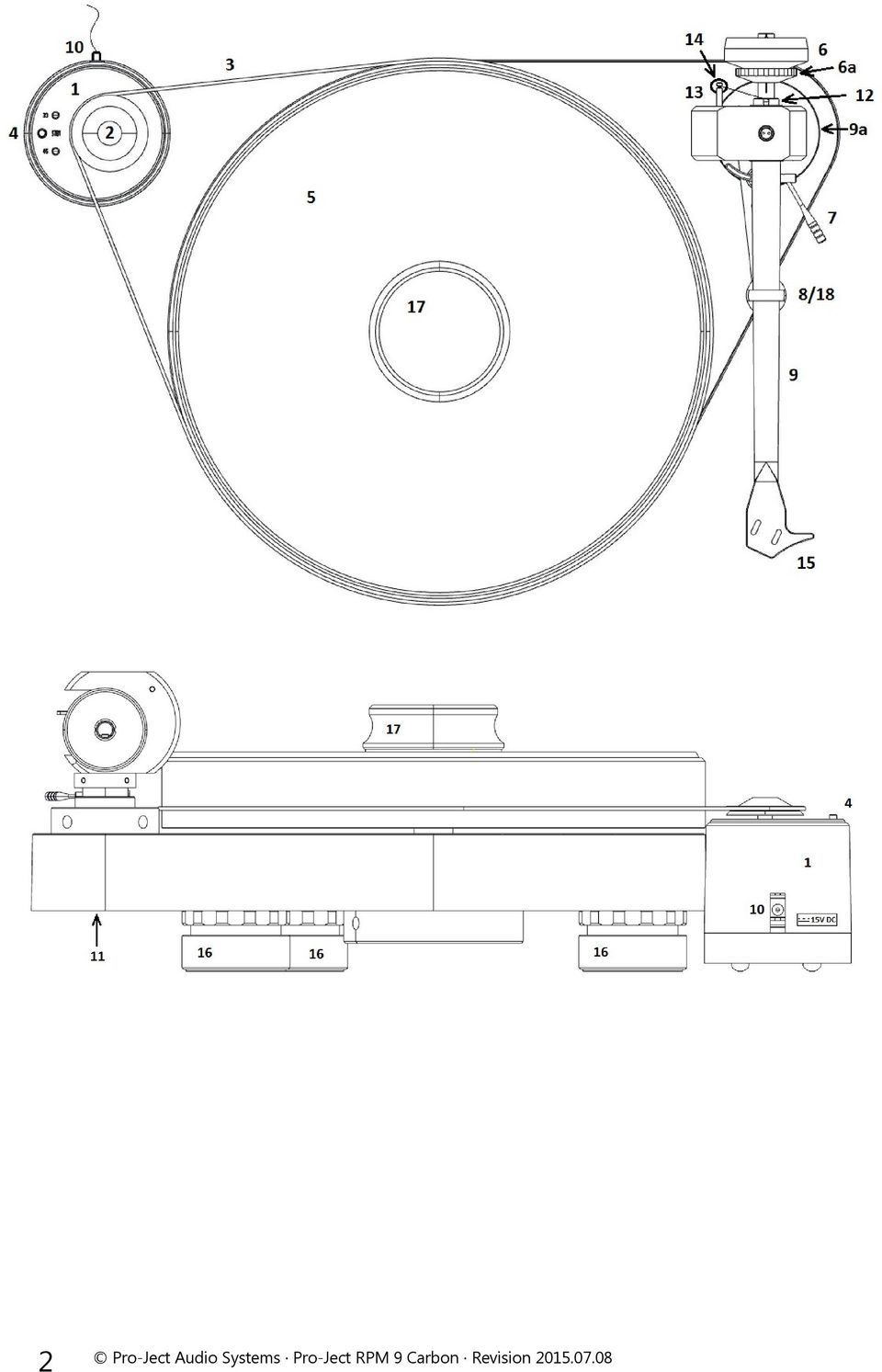
3 Pro-Ject RPM 9 Carbon Controls, features and connections 1 Separate motor unit (motor and motor base) * 2 Drive pulley 3 Drive belt * 4 Speed control button 5 Platter * 6 Tonearm counterweight * 6a Downforce scale 7 Tonearm lift lever 8/18 Tonearm rest and removable transport lock 9 Tonearm tube 9a Tonearm base 10 Power supply socket 11 Phono output through 5-PIN connector 12 Anti-skating weight adjustment scale 13 Anti-skating weight * 14 Anti-skating weight wire support 15 Headshell with finger lift 16 Height-adjustable, magnet supported feet * 17 Record weight Signal cable Connect IT 5P-CC, 123cm (not shown) * Universal power supply (not shown) * Single adapter (not shown) * Spirit level (not shown) * Template (not shown) * 3
 * Universal power supply (not shown) * Single adapter (not shown) * Spirit level (not shown) *")
4 Dear music lover, thank you for purchasing a Pro-Ject Audio System s record player. In order to achieve maximum performance and reliability with this record player you should study these instructions for use carefully.! Warning of a hazard for the user, the unit or possible misuse. Important notice. The record player is supplied without cartridge or with a factory fitted and adjusted cartridge Ortofon QUINTET BRONZE. ** The following instructions for adjusting the cartridge are provided in case the cartridge is replaced by a different model at a later date. During assembly and adjustment of the deck small parts could be lost if not carefully placed in a suitable receptacle. Before starting assembly make yourself acquainted with the parts listed above and correspondingly numbered in the technical drawings above. Separately packed items are marked with an asterisk *. Safety instructions! The power supply is used to connect and disconnect the unit from the mains. Make sure that the plug is easily accessible at all times. Hold the plug when unplugging the power cord. Never handle the power cord while your hands are wet or damp. Avoid letting liquids enter the device. Never place any item containing liquid, such as a flower vase on or near the device. Never spill any liquid on the device. Never place any naked flame sources, such as lighted candles on or near the device. The product shall not be used in damp or wet locations, next to a bathtub, sink, swimming pool or any other similar conditions. Keep plastic bags away from children to prevent any risk of suffocation. Set-up The deck is supplied partially disassembled and carefully packaged for safe transport. Carefully remove all parts from the transport packaging. Screw the magnetic field feet (16) onto the threaded bolts located on the underside of the plinth. Make sure the surface you wish to use the turntable on is level (use the supplied spirit level) before placing the turntable on it. Carefully place the platter bearing housing over the bearing axle. Put the record weight on the platter and level the plinth using the supplied spirit level and the adjustable feet (16). Assemble motor and motor base. Place the motor unit to the left of the turntable. Position the motor unit with the aid of the supplied template. Fit the drive belt (3) around the platter (5) and the motor pulley (2). Avoid getting sweat or grease on the belt as these will deteriorate the performance and reduce the belt's lifespan. Use absorbent kitchen paper to remove any oil or grease from the outer edge of the hub and the belt. Remove the transport lock (18) from the tonearm. Store it in the original packaging so they are available for any future transportation. We recommend to use the record player without a mat on the platter. 4

5 Fitting and connecting the cartridge All cartridges with half inch mounting holes can be fitted. Leaving the needle's protection cover on, fit the cartridge to the headshell using the screws supplied with the cartridge by passing one screw through each slot in the headshell (15). Do not tighten the nuts yet. Connect the tonearm wires to the cartridge pins as follows: white red left channel positive (L+) right channel pos. (R+) green right channel return (R -) blue left channel return (L -) The full sound quality of the record player can only be achieved if the cartridge is correctly adjusted. Particular tools like the Pro-Ject alignment tool are required to accomplish this job properly. If you are not well acquainted with the adjustment of cartridges you are advised to call upon the willing help of your Pro-Ject dealer to accomplish this task for you. Please note: adjusting a cartridge and tonearm calls for the greatest care in order to avoid damaging the cartridge or tonearm bearings. Leave this work to your dealer if you are in any way unsure of the necessary steps and precautions to be taken. Cartridge downforce adjustment The counterweights (6) supplied are suitable for cartridges weighing between 5-7,5g (counterweight no. 28), 7-10g (counterweight no. 46), 9-11g (counterweight no. 43) or 10-14g (counterweight no. 29). Adjust the downforce prior to installing the anti-skating weight. Pushing carefully, turn the counterweight (6) onto the rear end of the tonearm tube (9), so that the downforce scale (6a) shows towards the front of the player. Lower the armlift and position the cartridge in the space between arm rest and platter. Carefully rotate the counterweight (6) until the armtube balances out. The arm should return to the balanced position if it is moved up or down. This adjustment must be done carefully. Do not forget to remove the cartridge protection cap if fitted. Once the arm is correctly balanced return it to the rest. Hold the counterweight (6) without moving it, and gently revolve the downforce scale ring (6a) until the zero is in line with the anti-skating stub (12). Check whether the arm still balances out. Rotate the counterweight counter clockwise (seen from the front) to adjust the downforce according to the cartridge manufacturer's recommendations. One mark on the scale represents 1 mn (= 0,1g / 0,1 Pond) of downforce. Adjusting the vertical tracking angle (vta) Put a record and the record weight on the platter. When the needle is lowered into the record groove and the tonearm is not resting on the lift arm, the tube of the tonearm should be parallel to the surface of the record. If it is not loosen both hexagon screws in the tonearm base just enough to allow vertical movement of the arm pillar without force and slide the arm up or down until it is parallel. Carefully retighten the hexagon screws without applying excessive force (which would deform the arm pillar) finger tight is quite sufficient. 5
 green right channel return (R -) blue left channel return (L -) The full sound quality of the record player can only be achieved if the cartridge is correctly adjusted.")
6 Adjusting the azimuth The cartridge needle must be vertical in the record groove in order to trace the groove wall modulations correctly. A small screw at the bearing end of the arm allows incorrect azimuth to be corrected if your needle is not mounted exactly perpendicular to the cartridge body (which is often the case). Slacken off the screw just enough to be able to revolve the arm tube without applying force. Note! Do not remove the screw completely! With the aid of a good magnifying glass adjust the needle until it is vertical in the groove (i.e. perpendicular to the record's surface). Ideally this should correspond to the top surface of the cartridge body being parallel to the record surface, but in practice this is often not the case. When you are satisfied that the needle is vertical retighten the screw carefully. Screw Under no circumstances should the arm tube be adjusted with the needle still in the record groove! Irreparable damage may be caused to the cantilever suspension! The arm must be lifted to make each adjustment and lowered afterwards to check it. Anti-skating force adjustment The anti-skating force must be adjusted corresponding to the downforce as follows: Downforce Groove in the stub (15) 10-14mN 1 st from bearing rings 15-19mN 2 nd " " " 20mN and bigger 3 rd " " " Hang the loop of the thread of the anti-skating weight in the groove of the anti-skating stub (12) corresponding to the downforce applied to your cartridge and hang the thread in the groove of the wire support (14). Connection to the amplifier The record player has output through 5 PIN connector (11). Use supplied cable Pro-Ject Connect IT 5P- CC to connect the turntable to the amplifier. Use the Phono input (sometimes labelled gram, disc or RIAA) on your amplifier. Make sure that the phono input offers correct matching and amplification for the type of cartridge used. Line inputs (such as CD, Tuner, Tape or Video) are not suitable. Take care to connect the left and right channels correctly. The right channel is usually marked red, the left channel black or white. Check the manual supplied with your amplifier for relevant information. An earthing wire may be connected to the screw terminal between the sockets if you encounter hum problems when using the record player. If your amplifier does not have an input suitable for phono cartridges you will require a separate phono amplifier stage for MM or MC cartridges which is then connected between the record player and a free line level input of the amplifier. For detailed product information regarding Pro-Ject Audio interconnect cables and phono amplifiers please refer to the Pro-Ject web site Mains power connection The turntable is supplied with the universal power supply with 3 exchangeable sockets adapters suitable for all countries. Select the correct adapter for your country and insert the adapter to the exchangeable part of the power supply. Connect the low voltage plug from the power supply to the socket (10) on the rear of the record player before connecting the power supply to the mains. 6
.")
7 Switching on and off Pressing the speed control button (4) alternately starts or stops the motor. Changing replay speed Press the speed control button STBY (4) to start the turntable. For change the speed from 33 r.p.m. to 45 r.p.m., please press the STBY (4) button again. Speed is correct, when the LED diode stops blinking. To switch turntable to STAND BY mode, please hold the button STBY (4) for 3 seconds. For detailed product information please refer to the Pro-Ject web site Fitting the optional lid Fit the lid carefully on to the record player from above. Maintenance and cleaning Your record player requires little or no regular maintenance. Remove dust with a slightly moistened antistatic cloth. Never use a dry cloth because this will create static electricity which attract more dust! Antistatic cleaning fluids are available at specialist stores but must be applied sparingly to avoid damage to rubber parts. It is recommended to fit the needle cover before cleaning or maintenance is carried out to avoid damage. If the player is not used over a long period of time the drive belt can be removed to prevent unequal stretching.! Useful tips Always disconnect the record player from the mains power supply as a precaution before maintenance! The lid (optional) is not only a dust cover but also a resonant structure likely to be excited by, and to pass into the plinth, the acoustic energy emanating from your loudspeakers during replay. It is therefore recommended that the lid be removed for optimum sound quality. The record player should be positioned on a low-resonance surface such as wood or multiple layer ply board to avoid structural vibrations disturbing replay. Technical specifications PRO-JECT RPM 9 Carbon / Pro-Ject 9cc Evolution Nominal speeds 33/45 r.p.m. Speed variance ±0,1 % Wow and flutter ±0,07 % Signal to noise Effective tonearm mass Effective tonearm length Overhang Power consumption Outboard power supply Dimensions (W x H x D) Weight 73dB 8g 9 " (230mm) 18mm 12W max / <0,3W stanby 15V DC / 1,6A AC, V AC, 47 63Hz 440 x 180 x 325mm 16,5kg 7

8 Potential incorrect use and fault conditions Pro-Ject turntables are manufactured to the highest standards and undergo strict quality controls before leaving the factory. Faults that may possibly occur are not necessarily due to material or production faults but can sometimes be caused by incorrect use or unfortunate circumstances. Therefore the following list of common fault symptoms is included. The platter doesn't turn although the unit is switched on: The unit is not connected to the mains power supply. No mains at the socket. Drive belt is not fitted or has slipped off. No signal through one or other channel or both channels: No signal contact from the cartridge to the internal tonearm wiring or from that to the arm lead or from that to the phono box or between that and the amplifier. This could be due to a faulty plug, broken wire or solder joint or simply loose plug/socket connection. Phono input not selected at amplifier. Amplifier not switched on. Amplifier or speakers defective or muted. No connection to the loudspeakers. Strong hum on phono input: No earth connection from cartridge or arm or arm cable to amplifier, or earth loop. Distorted or inconsistent sound from one or both channels: Record player is connected to wrong input of amplifier, or MM/MC switch incorrectly set. Needle or cantilever damaged. Wrong r.p.m., drive belt overstretched or dirty, platter bearing without oil, dirty or damaged. Service Should you encounter a problem which you are not able to alleviate or identify despite the above information, please contact your dealer for further advice. Only when the problem cannot be resolved there should the unit be sent to the responsible distributor in your country. Guarantee repairs will only be effected if the unit is returned correctly packaged. For this reason we recommend keeping the original packaging. Never return a record player without making sure that is it safely disassembled and correctly packaged in the original packaging according to the diagrams on the last page of this user guide. Please remove these parts and pack them separately: lid (10), counterweight (6), anti-skating weight (16) platter (5) and belt (3). Fit the cartridge protection cap. Insert the transport lock for the tonearm (18) prior to carefully packaging the record player. Warranty The manufacturer accepts no responsibility for damage caused by not adhering to these instructions for use and/or by transportation without the original packaging. Modification or change to any part of the product by unauthorized persons release the manufacturer from any liability over and above the lawful rights of the customer. Pro-Ject Audio Systems is a Registered Trademark of H. Lichtenegger. This guide was produced by: Pro-Ject Audio Systems Copyright All rights reserved. The information was correct at the time of going to press. The manufacturer reserves the right to make changes to the technical specification without prior notice as deemed necessary to uphold the ongoing process of technical development. 8

9 Accessories! Please remove feet bevore repacking Tonearm transport lock Motor base Motor Record weight Platter Tonearm counterweight Power supply 9

INSTRUCTIONS FOR USE. Pro-Ject RPM 9 Carbon
 INSTRUCTIONS FOR USE Pro-Ject RPM 9 Carbon 2 Pro-Ject RPM 9 Carbon Controls, features and connections 1 Separate motor unit (motor and motor base) * 2 Drive pulley 3 Drive belt * 4 Speed control button
INSTRUCTIONS FOR USE Pro-Ject RPM 5.1
 INSTRUCTIONS FOR USE Pro-Ject RPM 5.1 1 1 2 PRO-JECT RPM 5.1 Controls, features and connections 1 Motor transportation screw (marked red) 2 Stepped drive pulley 3 Drive belt * 3a Hook * 4 Hub 5 Platter
INSTRUCTIONS FOR USE Pro-Ject RPM 1.3 Genie
 INSTRUCTIONS FOR USE Pro-Ject RPM 1.3 Genie 1 8 9 10 4 12 13 11 2 6 16 5 3 7 14 Controls, features and connections 1/11 Power switch, motor unit with stepped drive pulley 2 Drive belt * 3 Platter 4 Tonearm
INSTRUCTIONS FOR USE Pro-Ject Essential II
 INSTRUCTIONS FOR USE Pro-Ject Essential II 12 14 14 10 22 4 30 0 5 4a 9 2 8 3 66 6 5 7 1 11 14 13 Controls, features and connections 1 Power switch 2/22 Stepped drive pulley and drive belt * 3 Platter
INSTRUCTIONS FOR USE Pro-Ject RPM 1 Carbon
 INSTRUCTIONS FOR USE Pro-Ject RPM 1 Carbon 2 Controls, features and connections 1/11 Power switch, motor unit with stepped drive pulley 2 Drive belt * 3 Platter, felt mat 4 Tonearm counterweight 5 Tonearm
INSTRUCTIONS FOR USE Pro-Ject 1 Xpression Carbon Classic
 INSTRUCTIONS FOR USE Pro-Ject 1 Xpression Carbon Classic 2 Pro-Ject 1 Xpression Carbon Classic Controls, features and connections 1 Motor brackets with ORTOFON pads 2 Stepped drive pulley 3 Drive belt
INSTRUCTIONS FOR USE Pro-Ject 2 Xperience SB
 INSTRUCTIONS FOR USE Pro-Ject 2 Xperience SB 2 Pro-Ject 2 Xperience SB Controls, features and connections 1 Motor transport foam inserts 2 Motor pulley 3 Drive belt * 4 Sandwich platter * 5 Tonearm counterweight
INSTRUCTIONS FOR USE Pro-Ject Debut Carbon Esprit SB
 INSTRUCTIONS FOR USE Pro-Ject Debut Carbon Esprit SB 11 11 21 2 1 3 16 6 30 0 5 6a 17 15 9a 1 4 5 8 18 9 7 20 33 45 STBY 19 17 9a 22 10 11 12 14 13 2 Pro-Ject Debut Carbon Esprit SB Controls, features
INSTRUCTIONS FOR USE Pro-Ject Tube Box S
 INSTRUCTIS FOR USE Pro-Ject Tube Box S Dear music lover, thank you for purchasing a PRO-JECT AUDIO phono amplifier. In order to achieve maximum performance and reliability you should study these instructions
INSTRUCTIONS FOR USE Pro-Ject Phono Box II USB
 INSTRUCTIONS FOR USE Pro-Ject Phono Box II USB Dear music lover, thank you for purchasing a PRO-JECT AUDIO phono amplifier. In order to achieve maximum performance and reliability you should study these
SETUP MANUAL FOR JMW TONEARM 10.5 AND 12.5 VERSION READ THIS MANUAL VERY CAREFULLY NOT FOLLOWING THIS MANUAL WILL VOID YOUR WARRANTY
 SETUP MANUAL FOR JMW TONEARM 10.5 AND 12.5 VERSION READ THIS MANUAL VERY CAREFULLY NOT FOLLOWING THIS MANUAL WILL VOID YOUR WARRANTY FAILURE TO FILL OUT THE WARRANTY WILL VOID YOUR WARRANTY http://vpiindustries.com/warranty/
CONTENTS INTRODUCTION 1 DESIGN INNOVATION 2-4 INSTALLATION 4-5 CONNECTION TO THE AMPLIFIER 6 POWER SUPPLY 6-7
 - CONTENTS INTRODUCTION 1 DESIGN INNOVATION 2-4 INSTALLATION 4-5 CONNECTION TO THE AMPLIFIER 6 POWER SUPPLY 6-7 CONTROL AND CONNECTION ILLUSTRATIONS 8-9 TRANSPORTING YOUR TURNTABLE 9 CARE OF THE TURNTABLE
MBSAW. Meat Cutting Band Saw With Meat Grinder Assembly & Operating Instructions
 06/2011 MBSAW Meat Cutting Band Saw With Meat Grinder Assembly & Operating Instructions READ ALL INSTRUCTIONS AND WARNINGS BEFORE USING THIS PRODUCT. This manual provides important information on proper
Brio-Rmanual:Cursamanual.qxd 08/04/2011 09:25 Page1
 - Brio-Rmanual:Cursamanual.qxd 08/04/2011 09:25 Page1 Brio-Rmanual:Cursamanual.qxd 08/04/2011 09:25 Page2 CONTENTS INTRODUCTION, FEATURES AND TECHNOLOGY 1-3 INSTALLATION 3 CONNECTIVITY 4-6 LOUDSPEAKER
STEREO PREAMPLIFIER INSTRUCTIONS FOR USE
 XX STEREO PREAMPLIFIER INSTRUCTIONS FOR USE Thank you for purchasing the Musical Fidelity A5 CR Preamplifier. Used properly and carefully, it should give many years of outstanding musical reproduction.
Record Cleaning Machine
 Record Cleaning Machine Owner s Manual UK December 2010 Photo 1 Photo 2 IMPORTANT! READ THIS OWNER S MANUAL CAREFULLY, BEFORE USING THE MACHINE! Introduction You are now the proud owner of an Okki Nokki
Tone Hammer 500. Owners Manual. Manual Version 1.0
 Tone Hammer 500 Owners Manual Manual Version 1.0 1. Incorporating the preamp from the popular Tone Hammer preamp/di pedal this superlight bass head combines three bands of flexible EQ, a colorful "Drive"
Perseus. Owner s Manual. Vacuum Tube Preamplifier. Rogue Audio, Inc. 3 Marian Lane Brodheadsville, PA 18322. Issue date: 02/01/06
 Perseus Vacuum Tube Preamplifier Owner s Manual Rogue Audio, Inc. 3 Marian Lane Brodheadsville, PA 18322 Issue date: 02/01/06 TABLE OF CONTENTS 1) Introduction 2 2) Unpacking the Perseus Preamplifier 2
- 2 - IMPORTANT SAFETY REMINDERS
 USER MANUAL IMPORTANT SAFETY REMINDERS This appliance should only be used for domestic cleaning, as described in this user guide. Please ensure that this guide is fully understood before operating the
3. Loosen 3 x grub screws in the Dec end cap and unscrew the cap and counterweight shaft. NEQ6 Belt Modification Kit.
 NEQ6 Belt Modification Kit. Thank you for your purchase. Please read these instructions fully before fitting. Your package should contain 2 off 47 & 2 off 12 tooth aluminium pulleys 2 off belts 6mm wide
24 Wide Screen LED Monitor with HDMI
 24 Wide Screen LED Monitor with HDMI USER MANUAL L24LE11B_MANUAL_EN_R1 Please read this manual carefully before using, and keep it for future reference. TABLE OF CONTENTS GETTING STARTED Monitor Stand
EZ-Steer Assisted Steering System
 EZ-Steer Assisted Steering System Installation Instructions Platform Kit P/N 53059-21 Case IH Puma 165 Puma 180 Puma 195 Puma 210 New Holland T7030 T7040 T7050 T7060 Revision A June 2007 Part Number 53345-21-EU2
4.3-inch Back-Up Camera
 TM 4.-inch Back-Up Camera Model No.: PKC0BU4 Owner s Manual and Warranty Information Read these instructions completely before using this product. Retain this Owner s Manual for future reference. INTRODUCTION
USER INSTRUCTIONS FOR 10 LITRE PORTABLE DEHUMIDIFIER MODEL NO. DHMD102
 USER INSTRUCTIONS FOR 10 LITRE PORTABLE DEHUMIDIFIER MODEL NO. DHMD102 THANK YOU FOR CHOOSING YOUR NEW DEHUMIDIFIER. BEFORE USING THE UNIT READ THESE INSTRUCTIONS FULLY AND RETAIN THEM FOR FUTURE REFERENCE
EC4.8. BalancedReferencePreamplifier. Owner smanual ENG
 EC4.8 BalancedReferencePreamplifier Owner smanual ENG Unpacking the EC 4.8 Immediately upon receipt of the EC 4.8, inspect the carton for possible damage during shipment. The carton and packaging have
ATS Overhead Table Shelf System INSTRUCTION MANUAL
 ATS Overhead Table Shelf System INSTRUCTION MANUAL ATS Overhead Table Shelf System Instruction Manual Warranty Newport Corporation warrants this product to be free of defects in material and workmanship
Antenna Splitter ASA 1. Instruction manual
 Antenna Splitter ASA 1 Instruction manual Contents Important safety instructions... 2 The ASA 1 active antenna splitter... 4 Delivery includes... 4 Operating elements... 5 Putting the ASA 1 into operation...
EVID Compact Sound Speaker System
 EVID Compact Sound Speaker System EVID-C44, EVID-C2.1, EVID-40C, EVID-S44, EVID-S44W, EVID-2.1, EVID-2.1W, EVID-40S, and EVID-40SW en Installation Manual en 3 Table of contents 1 Safety 4 2 Welcome 6
SECTION G2: CABLE PROCESSOR MODULE MAINTENANCE
 SECTION G2: CABLE PROCESSOR MODULE MAINTENANCE Cable Processor Module overview WARNING! When tipping the Cable Processor Module back, (after removing the toggle arm pin), use extreme caution not to drop
The Bose 601 TM Series IV Direct/Reflecting Speaker System
 The Bose 601 TM Series IV Direct/Reflecting Speaker System Owner s Guide October 25, 2001 AM257731_00_V.pdf Customer Information Declaration of Conformity We, the offerer: Bose Corporation, The Mountain,
Professional Disc Jockey Products TT-1510 Belt-Drive Turntable USER S MANUAL 2000 Industries http://www.numark.com
 Professional Disc Jockey Products TT-1510 Belt-Drive Turntable USER S MANUAL 2000 Industries http://www.numark.com Safety Information SAFETY INSTRUCTIONS 1. Read Instructions - All the safety and operating
Hegel H1 High End Integrated Amplifier
 Hegel H1 High End Integrated Amplifier www.hegel.com [email protected] USER GUIDE Congratulations on your new HEGEL! Our products are based on a simple philosophy: The component shall reproduce the original
Advantium 2 Plus Alarm
 ADI 9510-B Advantium 2 Plus Alarm INSTALLATION AND OPERATING INSTRUCTIONS Carefully Read These Instructions Before Operating Carefully Read These Controls Corporation of America 1501 Harpers Road Virginia
Gemini II. Subwoofer System OWNERS MANUAL
 Gemini II Subwoofer System OWNERS MANUAL CONTENTS Page No. 1) Safety instructions. 2) 3) 4) Connecting up your Gemini II. Connecting up using the high level input. Connecting up using the low level input.
Original Assembly Guide
 TCT Multipurpose Single Bevel Sliding Compound Mitre Saw Original Assembly Guide Read instructions before assembling this tool. Table of Contents GB Assembly Guide Read instructions before assembling this
12-Volt 10-Amp Regulated Power Supply
 22-506.fm Page 1 Friday, August 6, 1999 12:55 PM Cat. No. 22-506 OWNER S MANUAL Please read before using this equipment. 12-Volt 10-Amp Regulated Power Supply 22-506.fm Page 2 Friday, August 6, 1999 12:55
Awning Instructions. Full Cassette 1.5m to 6m
 Awning Instructions Full Cassette 1.5m to 6m English Full Cassette Manual & Electric Instructions Contents Warning 1.5m - 3.5m Awnings 8 x Expansion bolts ** 2 x brackets 1 x Awning 1 x Winder 4.0m -
Owners & Installation Manual for the Sheridan, Mountainair, Pine Valley and Old Forge Ceiling Fan Family
 Owners & Installation Manual for the Sheridan, Mountainair, Pine Valley and Old Forge Ceiling Fan Family Part of the Kiva Lighting Family Custom Lighting and Fans Since 1992 1312 12th St NW Albuquerque,
Assembly and Usage Instructions
 Assembly and Usage Instructions A Product 5885 West Van Horn Tavern Road Columbia, MO 65203 www.caldwellshooting.com Instruction #1001667 Limited Warranty Every Caldwell product is warrantied to be free
LED 18W/12V SWIMMING POOL LIGHT WITH REMOTE CONTROL INSTALLATION AND OPERATING INSTRUCTIONS
 LED 18W/12V SWIMMING POOL LIGHT WITH REMOTE CONTROL INSTALLATION AND OPERATING INSTRUCTIONS i Read the operating instructions Contents I. Pack contents... 3 II. Basic information... 3 III. Positioning
Active Monitor Box McCrypt S.T.E.V.E. 15. Order No. 30 17 06
 Active Monitor Box McCrypt S.T.E.V.E. 15 Order No. 30 17 06 1 McCrypt Active Monitor 15 Introduction Dear Customer, Thank you for purchasing this McCrypt Active Monitor. You have chosen a quality product
STEERING HANDLEBAR/FRONT WHEEL/ FRONT SHOCK ABSORBER
 14 14 STEERING HANDLEBAR/FRONT WHEEL/ SCHEMATIC DRAWING ------------------------------------------------- 14-1 SERVICE INFORMATION------------------------------------------------ 14-2 TROUBLESHOOTING-----------------------------------------------------
OEM Manual MODEL 2350 ELECTRONIC DUAL CYLINDER SCALE
 OEM Manual MODEL 2350 ELECTRONIC DUAL CYLINDER SCALE Scaletron Industries, Ltd. Bedminster Industrial Park 53 Apple Tree Lane P.O. Box 365 Plumsteadville, PA 18949 USA Toll Free: 1-800-257-5911 (USA &
Remote Head REMO ONE. Code 5750. Manual
 Remote Head REMO ONE Code 5750 Manual by sachtler. All rights reserved Version: 1.2/09/05 Issue date: September 2005 Order no.: srh20t010a We want you to receive Sachtler products that are always state
Pet hair clipper. Model 96822. Diagrams within this manual may not be drawn proportionally.
 Pet hair clipper Model 96822 Cleaning And Operation Instructions Diagrams within this manual may not be drawn proportionally. Due to continuing improvements, actual product may differ slightly from the
Auto-belay Cable Replacement Process
 Auto-belay Cable Replacement Process Version 2.00 WARNING: The air pressure in the auto-belay system is what causes the cable to be retracted when releasing the cable or climbing the wall with the cable
EZ-Steer Assisted Steering System
 EZ-Steer Assisted Steering System Installation Instructions Platform Kit P/N 53059-54 Case IH CVX 1135 CVX 1145 CVX 1155 CVX 1170 CVX 1190 CVX 1195 CVX 135 CVX 145 CVX 155 CVX 175 CVX 195 New Holland TVT
Express5800/120Ed. Rack Mount Kit Installation Procedures PN: 455-01607-001
 Express5800/120Ed Rack Mount Kit Installation Procedures PN: 455-01607-001 Proprietary Notice and Liability Disclaimer The information disclosed in this document, including all designs and related materials,
XLS200 MKII. Subwoofer System OWNERS MANUAL
 XLS200 MKII Subwoofer System OWNERS MANUAL CONTENTS Page No. 1) Safety instructions. 2) 3) 4) Connecting up your XLS200. Connecting up using the high level input. Connecting up using the low level input.
S-8, S-10 AND S-12 POWERED SUBWOOFER. Owner s Manual
 S-8, S-10 AND S-12 POWERED SUBWOOFER Owner s Manual Introduction Congratulations on your purchase of an RBH Sound powered subwoofer! Your subwoofer is the result of many years of research and development
INFRARED QUARTZ WALL HEATER
 INFRARED QUARTZ WALL HEATER MODEL NO: IQ2000 PART NO: 6939004 MOUNTING & OPERATION INSTRUCTIONS GC0715 INTRODUCTION Thank you for purchasing this CLARKE Infrared Wall Heater. Before attempting to use this
Time needed: ~3h for lid replacement only. Add 1h for operation harness in lid and ~2h more for installing drive unit and cable harness in trunk.
 DIY for replacing trunk lid and/or retrofitting electrical operation of trunk lid. This document is meant to be a support and give advice on the procedure but I will take no responsibility for any damage
HP ProDisplay P19A LED Backlit Monitor. User Guide
 HP ProDisplay P19A LED Backlit Monitor User Guide 2013 Hewlett-Packard Development Company, L.P. The only warranties for HP products and services are set forth in the express warranty statements accompanying
1. SAFETY RULES. 8. Avoid placing objects in the path of the blades.
 1 1. SAFETY RULES 1. To reduce the risk of electric shock, insure electricity has been turned off at the circuit breaker or fuse box before beginning. 2. All wiring must be in accordance with the National
6 inch A-Arm Lift Kit WARNING: 16-018/16-019. installation instructions. will fit CLUB CAR DS. included:
 Revised May 205 6-08/6-09 6 inch A-Arm Lift Kit will fit CLUB CAR DS installation instructions included: Rear Lift Blocks Main Suspension Assembly Spindles A-Arms Rear Shock Mounting Plates U-Bolts WARNING:
user guide Meridian 558 Multi Channel Power Amplifier
 user guide Meridian 558 Multi Channel Power Amplifier Meridian 558 Multi Channel Power Amplifier User Guide ipreface Sales and service in the UK Meridian Audio Ltd Stonehill Stukeley Meadows Cambs PE18
ELECTRIC KNIFE SHARPENER
 PRODUCT MANUAL- M109 MODEL 401 ELECTRIC KNIFE SHARPENER Please read thoroughly before operation and keep for future reference Model 401 Knife Sharpener Specifications Model No. #401 Power Requirements
Congratulations! Thank you!
 TM-47 ORDERCODE D1370 Congratulations! You have bought a great, innovative product from DAP Audio. The DAP Audio Microphone range brings excitement to any venue. Whether you want simple plug-&-play action
ZAPPY 3 OWNER S MANUAL. Read this manual completely before riding your Electric ZAPPY 3.
 ZAPPY 3 OWNER S MANUAL Read this manual completely before riding your Electric ZAPPY 3. TECHNICAL INFORMATION Model No. : ZAPPY 3 Product size Type of motor Motor power Battery type Battery Charger Charging
Andersen Electric Window Opener for Andersen Awning and Roof Windows
 W A Electric Window Opener Electric Window Opener for Awning and Roof Windows Congratulations! You have just purchased one of the many fine products. For ease of installation and continued enjoyment of
F25 REMOTE CONTROL STEREO PREAMPLIFIER INSTRUCTIONS FOR USE
 REMOTE CONTROL STEREO PREAMPLIFIER INSTRUCTIONS FOR USE Thank you for purchasing the Musical Fidelity Preamplifier. Used properly and carefully, it should give you many years of outstanding musical reproduction.
MODEL: MEMPHIS FM STEREO RADIO OPERATING INSTRUCTIONS
 MODEL: MEMPHIS CD/USB/SD PLAYER WITH TURNTABLE. ENCODING TO USB AND SD CARD. FM STEREO RADIO OPERATING INSTRUCTIONS PLEASE READ THIS USER MANUAL COMPLETELY BEFORE OPERATING THIS UNIT AND RETAIN THIS BOOKLET
Operation Manual Magic Bowling. Warning Please read this manual carefully before using this machine
 Operation Manual Magic Bowling Warning Please read this manual carefully before using this machine Preface 1. Company profile: Zhongshan star amusement equipment Co., Ltd, ltd, which designs and manufactures
Doorbell Intercom Security System
 Doorbell Intercom Security System POWER IN USE OFF A B C LOCK CALL TALK Installation Guide Model WHDB-301 EXPLANATION OF GRAPHIC WARNING SYMBOLS This symbol is intended to alert the user to the presence
USER MANUAL. 914 Power Amplifier MODEL: P/N: 2900-300280 Rev 1
 KRAMER ELECTRONICS LTD. USER MANUAL MODEL: 914 Power Amplifier P/N: 2900-300280 Rev 1 Contents 1 Introduction 1 2 Getting Started 2 2.1 Achieving the Best Performance 2 3 Overview 3 3.1 Energy Star 3
SERVICE GUIDE. Gateway Notebook
 SERVICE GUIDE Gateway Notebook Contents Replacing Gateway Notebook Components...................................1 Identifying the notebook model......................................... 2 Identifying
Service Guide. Gateway M275
 Service Guide Gateway M275 Contents Replacing Gateway M275 Components.................................... 1 Identifying the convertible tablet PC model...................................... 2 Identifying
BUILT-IN DISHWASHER INSTALLATION INSTRUCTIONS
 BUILT-IN DISHWASHER INSTALLATION INSTRUCTIONS PLEASE READ COMPLETE INSTRUCTIONS BEFORE YOU BEGIN LEAVE INSTALLATION INSTRUCTIONS AND USER'S GUIDE WITH OWNER ALL ELECTRIC WIRING AND PLUMBING MUST BE DONE
Wall-Mounting your HP computer. User Guide
 Wall-Mounting your HP computer User Guide The only warranties for Hewlett-Packard products and services are set forth in the express statements accompanying such products and services. Nothing herein should
AMERBRITE UNDERWATER WHITE LED POOL LAMP
 AMERBRITE UNDERWATER WHITE LED POOL LAMP FOR USE ONLY WITH PENTAIR AMERLITE LUMINAIRE INSTALLATION AND USER S GUIDE IMPORTANT SAFETY INSTRUCTIONS READ AND FOLLOW ALL INSTRUCTIONS SAVE THESE INSTRUCTIONS
JANUS INTERNATIONAL CORPORATION INSTALLATION INSTRUCTIONS Pantheon Mini Operator
 JANUS INTERNATIONAL CORPORATION INSTALLATION INSTRUCTIONS Pantheon Mini Operator The Janus Pantheon mini operator does not typically require the provision of any additional site requirements other than
1000-LB. TRAILER JACK OWNER S MANUAL
 1000-LB. TRAILER JACK OWNER S MANUAL WARNING: Read carefully and understand all INSTRUCTIONS before operating. Failure to follow the safety rules and other basic safety precautions may result in serious
HOME GYM. Model. Retain This Manual for Reference OWNER'S MANUAL. www.hyper-extension.com
 NOTE: Please read all instructions carefully before using this product Table of Contents Safety Notice www.hyper-extension.com HOME GYM 50036 Hardware Identifier Assembly Instruction Parts List Warranty
Front brakes (FN- 3), servicing
, servicing") j a t Front brakes (FN- 3), servicing 46-1 Front brakes, servicing Note: Install complete repair kit. After replacing brake pads and before moving vehicle, depress brake pedal several times firmly to properly
j a t Front brakes (FN- 3), servicing 46-1 Front brakes, servicing Note: Install complete repair kit. After replacing brake pads and before moving vehicle, depress brake pedal several times firmly to properly
OWNER S MANUAL. Permolock C3. Docking system for Power wheelchair in vehicle
 OWNER S MANUAL US Permolock C3 Docking system for Power wheelchair in vehicle How to contact Permobil Head Office of the Permobil group Permolock C3 Docking system for electric wheelchair in vehicle Produced
CONTENTS INTRODUCTION / EVOLUTION OF REVOLUTION 1 TURNTABLE DESIGN & MYTHOLOGY 2 DESIGN AND INNOVATION 3-7 SETTING UP YOUR RB808 7
 - CONTENTS INTRODUCTION / EVOLUTION OF REVOLUTION 1 TURNTABLE DESIGN & MYTHOLOGY 2 DESIGN AND INNOVATION 3-7 SETTING UP YOUR RB808 7 SETTING UP YOUR TURNTABLE 8 TTPSU / CONNECTION TO THE AMPLIFIER 9 TTPSU
5800 Temperature Sensor Cable Assembly
 5800 Temperature Sensor Cable Assembly Removal and Replacement Instruction Sheet #60-4702-070 Revision D, January 14, 2013 Overview The 5800 has two refrigeration temperature sensors, one attached to the
INSTRUCTION. Industrial Sewing Machines. No. 010012. First published : June 1997 Second edition : March 2001
 INSTRUCTION Industrial Sewing Machines First published : June 1997 Second edition : March 2001 No. 010012 INTRODUCTION Thank you for your purchasing Kansai Special's DLR Series. Read and study this instruction
IMPORTANT INFORMATION - PLEASE READ. Table of Contents. Introduction. General Information
 IMPORTANT INFORMATION - PLEASE READ Introduction Congratulations! Welcome to the world of the ELLIPTICAL CROSS TRAINER. The ELLIPTICAL CROSS TRAINER is one of the finest and most comprehensive pieces of
16/32 Channel 1U Rack Mount CCTV Power Supply
 16/32 Channel 1U Rack Mount CCTV Power Supply Manual PH-A3224-GUQ Shown 16-Channel 32-Channel PTC PH-A1612-PUQ PH-A3224-PUQ Glass Fuse PH-A1612-GUQ PH-A3224-GUQ Industrial design 12 Amp 3 Amps per channel
Lunette 2 Series. Curved Fixed Frame Projection Screen. User s Guide
 Lunette 2 Series Curved Fixed Frame Projection Screen User s Guide Important Safety and Warning Precautions Please follow these instructions carefully to ensure proper maintenance and safety with your
LUCCI AIRFUSION QUEST II CEILING FAN
 LUCCI AIRFUSION QUEST II CEILING FAN WITH IR REMOTE INSTALLATION OPERATION MAINTENANCE WARRANTY INFORMATION CAUTION READ INSTRUCTIONS CAREFULLY FOR SAFE INSTALLATION AND FAN OPERATION. V1.0 QUEST II IR
Addendum to the Operating Instructions
 Drive Technology \ Drive Automation \ System Integration \ Services Addendum to the Operating Instructions MOVIMOT with AS-Interface and AC Motor DT/DV Unit Replacement MOVIMOT MM..C -> MM..D with MLK3A
BOSE. Link AL8 HOMEWIDE WIRELESS AUDIO LINK
 BOSE Link AL8 HOMEWIDE WIRELESS AUDIO LINK Français English SAFETY INFORMATION Please read this owner s guide Please take the time to follow the instructions in this owner s guide carefully. It will help
19 LED Tube Controller ORDERCODE 41003
 19 LED Tube Controller ORDERCODE 41003 Congratulations! You have bought a great, innovative product from Showtec. The Showtec 19 LED Tube Controller brings excitement to any venue. Whether you want simple
CINEMA SB100 powered soundbar speaker
 CINEMA SB100 powered soundbar speaker quick-start guide Thank You For Choosing This JBL Product The JBL Cinema SB100 powered soundbar speaker is a complete, integrated sound system that will dramatically
Operation Manual for Users
 Operation Manual for Users Model No.: FLTAMFMRCD!!!!!!!!!! ATTENTION!!!!!!!!!! THE RESET BUTTON MUST BE PRESSED TO ENSURE PROPER OPERATION. SEE INSTRUCTION MANUAL Table of Contents Table of Contents ---------------------------------------------------------------------------------------------
Router. A. Identify the major parts of the router. B. Complete a written test on safety and operating procedures of the router with 100% accuracy.
 Router I. Competencies Given a properly adjusted router, instruction and demonstration of use, each student will be able to: A. Identify the major parts of the router. B. Complete a written test on safety
SET-UP AND INSTALLATION FOR LEAD SCREW CARTRIDGE ASSEMBLY
 SET-UP AND INSTALLATION FOR LEAD SCREW CARTRIDGE ASSEMBLY 82-13-1 O-Ring (Rear) The Lead Screw Assembly is shipped separately. Note: Install Electrical and Pneumatic Circuitry. Be Sure electrical and pneumatic
User s Manual. Copyright 2014 Trick Technologies Oy
 User s Manual Copyright 2014 Trick Technologies Oy Catchbox Pro Module Catchbox Cover Contents 1 Safety Instructions...4-5 2 Quick Start... 6-15 3 Product Description... 16-18 Overview...16 Compatibility...17
SBC90. Abrasive Blast Cabinet Assembly & Operating Instructions
 SBC90 Abrasive Blast Cabinet Assembly & Operating Instructions READ ALL INSTRUCTIONS AND WARNINGS BEFORE USING THIS PRODUCT. SAVE THESE INSTRUCTIONS FOR FUTURE REFERENCE. This manual provides important
ROTARY TUMBLER INSTRUCTIONS AND PARTS LIST
 ROTARY TUMBLER INSTRUCTIONS AND PARTS LIST Model QT66 Model QT12 Model QT6 LORTONE 12130 Cyrus Way Mukilteo, WA 98275 (425) 493-1600 SETTING UP YOUR MACHINE Install The Barrel Guide: Using the machine
Replacing the Gateway M675 Keyboard
 Replacing the Gateway M675 Keyboard This package includes a replacement keyboard for your Gateway M675 notebook and these printed instructions. Tools you need You need a small Phillips screwdriver and
HOME THEATER SYSTEM. Instruction Manual. Model ASR150. Please read the instruction manual carefully before using your unit.
 SURROUND SOUND HOME THEATER SYSTEM Instruction Manual Model ASR150 Please read the instruction manual carefully before using your unit. For support visit : www.1800customersupport.com GENERAL TABLE OF
Step by step guide to installing your own Ku Band satellite dish
 Step by step guide to installing your own Ku Band satellite dish If you don't feel comfortable installing your own system, your local TV Aerial or Handyman can easily follow these helpful guidelines for
CX Zoner Installation & User Guide
 CX Zoner Installation & User Guide Cloud Electronics Limited 140 Staniforth Road, Sheffield, S9 3HF England Tel +44 (0)114 244 7051 Fax +44 (0)114 242 5462 e-mail [email protected] web site http://www.cloud.co.uk