Product Description Digital Solid State Starting Electric Fire Pump Controllers FTA1930
|
|
|
- Marianna Brook Conley
- 9 years ago
- Views:
Transcription
1 Product Description Digital Solid State Starting Electric Fire Pump Controllers FTA1930 Description Firetrol FTA1930 Digital Solid State Starting Fire Pump Controllers feature soft start, soft stop and system sensing capabilities that not only provide for reduced current starting, but also offer an improved level of hydromechanical performance. The controller monitors, displays and records fi re pump system information. When called to run, the motor will accelerate beginning at 100% of motor FLA up to a maximum of 300% FLA while rated torque is reduced to 15%. When stopping, the motor will decelerate to a preset level and pause, allowing for a restart if required, limiting stress in the piping system. If no additional starting causes are present, the motor will continue to decelerate to a full stop. This controller helps to reduce water hammer in the system. Approvals Firetrol fi re pump controllers are listed by Underwriters Laboratories, Inc., in accordance with UL218, Standard for Fire Pump Controllers, CSA, Standard for Industrial Control Equipment, and approved by Factory Mutual. They are built to meet or exceed the requirements of the approving authorities as well as NEMA and the latest editions of NFPA 20, Installation of Centrifugal Fire Pumps, and NFPA 70, National Electrical Code. Standard Features The following are included as standard with each controller: Voltage surge protector Main Disconnect Switch sized for connected motor horsepower and voltage Fire pump Circuit Breaker Suitable for use as Service Equipment Motor contactor Emergency Manual Run Mechanism to mechanically close motor contactor contacts in an emergency condition Built-in Start/Stop & Emergency Stop pushbuttons to bypass automatic circuits Door mounted display/interface panel featuring a 40 Character Vacuum Fluorescent Display, Membrane Type User Control Push-buttons and easy to read LED Indicators Single handle Isolating Disconnect Switch/Circuit Breaker mechanism Digital Solid State Soft Starter POWER ON LED PUMP RUN LED PHASE FAILURE LED PHASE REVERSAL LED LOW PRESSURE LED DELUGE OPEN LED INTERLOCK ON LED TRANSFER SWITCH NORMAL LED (If unit ordered with Automatic Power Transfer Switch) TRANSFER SWITCH EMERGENCY LED (If unit ordered with Automatic Power Transfer Switch) EMERGENCY ISOLATING SWITCH OFF LED (If unit ordered with Automatic Power Transfer Switch) Minimum Run Timer / Off Delay Timer Soft Start Bypass Timer Daylight Savings Time option Weekly Test Timer Motor Acceleration Timer Elapsed Time Meter Digital Pressure Display USB Host Controller and Port Solid State Pressure Transducer Data Log Event Log (3000 Events) True RMS Metering with simultaneous 3 phase display of amps and volts Disk Error message Disk Near Full message Pressure Error message Motor Over 320% message Local Start message Remote Start message Emergency Start message Fail To Start message Soft Starter Fault/Bypass message Undervoltage message Overvoltage message Low Suction Pressure message High Speed Open Serial Communications Port NEMA Type 2 enclosure

2 Specifications Digital Solid State Electric Fire Pump Controllers FTA1930 Main Fire Pump Controller The main fi re pump controller shall be a factory assembled, wired and tested unit and shall conform to all the requirements of the latest edition of NFPA 20, Standard for the Installation of Stationary Pumps for Fire Protection and NFPA 70, National Electrical Code. The controller shall be listed by Underwriters Laboratories, Inc., in accordance with UL218, Standard for Fire Pump Controllers, CSA, and Canadian Standards Association CSA-C22.2, Standard for Industrial Control Equipment (culus), approved by Factory Mutual and approved by the City of New York for fi re pump service. Starting Method The controller shall be of the combined manual and automatic type designed for reduced current soft starting/stopping of the fi re pump motor having the horsepower, voltage, phase and frequency rating shown on the plans and drawings. The controller components shall be housed in a NEMA Type 2 (IEC IP11) drip-proof, wall mounted enclosure. Withstand Ratings (Short Circuit Current Ratings) All controller components shall be front mounted, wired and front accessible for maintenance. The minimum withstand rating of the controllers shall not be less than 100,000 Amps RMS Symmetrical at Volts*. If the available system fault current exceeds these ratings, the controllers shall be supplied with a withstand rating of 150,000 or 200,000 Amps RMS Symmetrical, as required. *Note: 100,000 Amp withstand rating not available in some larger horsepowers. Consult factory for details. Isolation Switch and Circuit Breaker The controller shall include a motor rated combination isolating disconnect switch/circuit breaker, mechanically interlocked and operated with a single, externally mounted handle. When moving the handle from OFF to ON, the interlocking mechanism shall sequence the isolating disconnect switch ON first, and then the circuit breaker. When the handle is moved from ON to OFF, the interlocking mechanism shall sequence the circuit breaker OFF fi rst, and then the isolating disconnect switch. The isolating disconnect switch/circuit breaker shall be mechanically interlocked so that the enclosure door cannot be opened with the handle in the ON position except by a hidden tool operated defeater mechanism. The isolating disconnect switch/circuit breaker shall be capable of being padlocked in the OFF position for installation and maintenance safety, and shall also be capable of being locked in the ON position without affecting the tripping characteristics of the circuit breaker. The controller door shall have a locking type handle and three point cam and roller vault type hardware. The circuit breaker trip curve adjustment shall be factory set, tested and sealed for the full load amps of the connected motor. The circuit breaker shall be capable of being field tested to verify actual pick up, locked rotor, and instantaneous trip points after fi eld installation without disturbing incoming line and load conductors. Operator Interface The fire pump controller shall feature an operator interface with user keypad. The interface shall monitor and display motor operating conditions, including all alarms, events, and pressure conditions. All alarms, events, and pressure conditions shall be displayed with a time and date stamp. The display shall be a 2-line, 20-character, vacuum fl uorescent, dot matrix type designed to allow easy viewing from all angles and in all light conditions. The display and interface shall be NEMA rated for Type 2, 3R, 4, 4X, and 12 protection and shall be fully accessible without opening the controller door. The display and user interface shall utilize multiple levels of password protection for system security. A minimum of 3 password levels shall be provided. The display shall be capable of being programmed for any language. Digital Soft Starter The digital soft starter parameters shall be programmable through the operator interface without the need to access the soft starter compartment. These settings shall include: Initial Starting Current (% FLA) Maximum Starting Current (% FLA) Acceleration Ramp Time (Seconds) Up To Speed/Stall Bypass Timer (Seconds) Deceleration Begin Level (% FLA) Deceleration Pause Level (% FLA) Deceleration Pause Time (Seconds) Deceleration End Level (% FLA) Deceleration Ramp Time (Seconds) Phase Order (ABC/CBA) Ammeter/Voltmeter The fi re pump controller operator interface shall be capable of displaying true RMS digital motor voltage and current measurements for all three phases simultaneously. Displays requiring pushbutton and selector switches to toggle between phases or current and voltage shall not be accepted. Voltage and current shall be measured by True RMS technology to provide the most accurate measurement for all sine waves, including nonsinusoidal waveforms. Average responding meters will not be accepted. Digital Status/Alarm Messages The digital display shall indicate text messages for the status and alarm conditions of: Motor On Sequential Start Time Minimum Run Time Local Start / Off Delay Time Remote Start Fail to Start System Battery Low Under Voltage Over Voltage Locked Rotor Trip Over Frequency Emergency Start Motor Over 320%
, approved by Factory Mutual and approved by the City of New York for fi re pump service.")
3 Drive Not Installed Disk Error Disk Near Full Motor Overload Soft Starter Fault/Bypass Pressure Error The Sequential Start Timer and Minimum Run Timer/ Off Delay Timer shall be displayed as numeric values refl ecting the value of the remaining time. LED Visual Indicators LED indicators, visible with the door closed, shall indicate: Power On Emerg. Isolating Switch Open Pump Running Low System Pressure Alarm Transfer Switch Normal Deluge Open Transfer Switch Emergency Phase Failure Phase Reversal Interlock On Data Logging The digital display shall monitor the system and log the following data: Motor Calls/Starts Elapsed Motor Run Time Last Trip Currents Elapsed Power On Time Last Breaker Trip Maximum Run Currents Minimum Voltages Minimum Run Currents Maximum Voltages Last Motor Run Time Last Phase Failure Last Start Currents Last Phase Reversal Min/Max Frequency Min/Max Pressure Event Recording Memory - The controller shall record all operational and alarm events to system memory. All events shall be time and date stamped and include an index number. The system memory shall have the capability of storing 3000 events and allow the user access to the event log via the user interface. The user shall have the ability to scroll through the stored messages in groups of 1, 10, or 100. USB Host Controller - The controller shall have a built-in USB Host Controller. A USB port capable of accepting a USB Flash Memory Disk (aka: flash drive, thumb drive, memory stick, etc..) shall be provided. The controller shall save all operational and alarm events to the fl ash memory on a daily basis. Each saved event shall be time and date stamped. The total amount of historical data saved shall solely depend on the size of the fl ash disk utilized. The controller shall have the capability to save settings and values to the fl ash disk via the user interface. Serial Communications - The controller shall feature a RS485 serial communications port for use with 2 or 4 wire Modbus RTU communications. used for both display of the system pressure and control of the fi re pump controller. Systems using analog pressure devices or mercury switches for operational control will not be accepted. The START, STOP and SYSTEM PRESSURE shall be digitally displayed and adjustable through the user interface. The pressure transducer shall be mounted inside the controller to prevent accidental damage. The pressure transducer shall be directly pipe mounted to a bulkhead pipe coupling without any other supporting members. Field connections shall be made externally at the controller coupling to prevent distortion of the pressure switch element and mechanism. Operation A digitally set On Delay (Sequential Start) timer shall be provided as standard. Upon a call to start, the user interface shall display a message indicating the remaining time value of the On Delay timer. The controller shall be fi eld programmable for manual stop automatic stop. If set for automatic stopping, the controller shall allow the user to select either a Minimum Run Timer or an Off Delay Timer. Both timers shall be programmable through the user interface. A weekly test timer shall be provided as standard. The controller shall have the ability to program the time, date, and frequency of the weekly test. In addition, the controller shall have the capability to display a preventative maintenance message for a service inspection. The message text and frequency of occurrence shall be programmable through the user interface. A Lamp Test feature shall be included. The user interface shall also have the ability to display the status of the system inputs and outputs. The controller shall not start the fi re pump motor under a single-phase condition. If the motor is already running when a phase loss occurs, the controller shall continue to run the motor, but still display a Phase Failure alarm. The fi re pump controller software shall be automatically upgradable through the USB port by simply inserting a flash disk with the new software. Fire pump controllers that require laptop computers, handheld equipment or specialized devices for software upgrades shall be prohibited. The controller shall be a Firetrol brand. Solid State Pressure Transducer The controller shall be supplied with a solid state pressure transducer with a range of psi ( bar) ±1 psi. The solid state pressure switch shall be SP ( ) (919) Sales Office: Cary, NC USA ASCO 2008

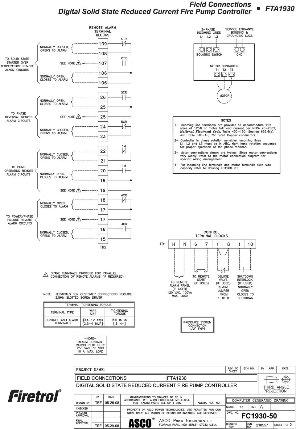
4 Sequence of Operation Digital Solid State Reduced Voltage Fire Pump Controllers FTA1930 Introduction Reference to Wiring Schematic, Publication WS Note: Firetrol schematics are drawn showing the equipment in a de-energized state. Energizing The Controller 1). Close the Isolating switch/circuit breaker by moving the handle to the ON position. Note: The unmarked, red, Interlock jumper wire, located between terminals #1 & #10 on the Relay PC board, (TB1), will prevent the MarkII unit from starting the electric motor automatically. This jumper wire should only be removed after the pressure settings have been input, and the system pressurized at, or above the Stop set point. 2). The factory programmed MarkII unit will begin initialization. Upon completion, the display will confi rm the system pressure, the time, date, and Interlock ON, which is an alarm condition and will cause the yellow alarm LED to fl ash. Any other existing alarm conditions (low system pressure, phase reversal, phase failure, deluge open), will also be sequentially and continuously displayed at this time, until each is rectifi ed. 3). With the interlock jumper still in place, the electric motor can only be started by depressing the START push-button, located on the flange of the controller enclosure, or by engaging the Emergency Run Mechanism. After all alarm conditions have been rectifi ed, and the system pressurized at or above the Stop pressure setting, then the interlock jumper may be removed for the controller s automatic operation ( standby ). With the interlock jumper removed, a drop in system pressure to the MarkII s set start point, will start the electric motor. 4). The deluge valve contacts are only operational if the factory jumper has been removed and a normally closed deluge valve contact has been placed between terminals 1 and 8 of the Relay PC board, (TB1). The Remote Start is only operational if a normally open, momentarily closed contact is wired to terminals 6 and 7 of the Relay PC board, (TB1). If engaged, the Emergency Run Mechanism will cause the pump motor to run as described in the Emergency Starting and Stopping section.. Automatic Start and Stop 1). The pressure transducer initiates the automatic start circuits for the pump motor. When pressure falls at or below the start setting, relay 1CR is energized. 1CR contact will close, initiating the soft start feature. Another 1CR contact closes, and activates the factory set (10 second) Bypass timer feature in the MarkII. The minimum run timer feature in the MarkII is also activated. When the soft starter reaches full speed, the 1MS full speed contact will open. Relay 6CR will energize and it s contact will close, energizing contactor 1M, connecting the motor at full voltage. The Bypass time in the MarkII will time out 10 seconds after the call to start. If the soft starter fails to reach full speed, the 6CR contact will close, energizing contactor 1M, connecting the motor at full voltage. Should the soft starter encounter an over temperature condition, the over-temperature switch in the soft starter will activate, energizing relay 6CR and the MarkII display will indicate Over Temperature Bypass. The 6CR contact will close, energizing contactor 1M, connecting the motor at full voltage. The minimum run time is a part of the MarkII Menu, Timer Settings. The minimum run time factory setting is 10 minutes. In this mode, minimum run time begins when the pressure falls at or below the Start set point, calling for the pump motor to run. When pressure is restored at or above the Stop set point and the minimum run timer expires, 1CR & 6CR coils will de-energize, re-opening the normally open contacts, de-energizing the 1M coil, and the soft starter is called to ramp down the motor. If pressure is restored at or above the Stop set point of the MarkII, and even if the minimum run time has not yet expired, the manual SOFT STOP, or EMERGENCY STOP push buttons, located on the flange of the controller can be depressed to manually stop the pump. This also resets the minimum run time function of the MarkII. The pump motor will run until the SOFT STOP pushbutton or the EMERGENCY STOP push-button is depressed. When the SOFT STOP push-button is pressed, an input to the soft starter STOP contact, initializes the ramp down sequence. If pressure has been restored, the ramp down sequence will continue until the motor is stopped. If pressure has not been restored at or above the STOP setting, the pump motor will restart when the push-button is released. When the EMERGENCY STOP push-button is pressed, it s input to the soft starter STOP contact signals the soft starter to stop immediately, bypassing the soft stop, whether pressure has been restored or not. Manual Start and Stop The pump motor may be manually started by using either the START push-button mounted on the flange of the enclosure or by using a normally open, momentarily closed, remote start push-button connected to terminals
.")
5 6 and 7. When the START push-button is depressed, or a remote start signal is seen through terminals 6 & 7, the MarkII will output through the relay pc board to 1CR relay coil and the sequence of events described in section Automatic Start & Stop will begin. The MarkII minimum run time feature will not be activated. The pump motor will continue to run until the SOFT STOP, or the EMERGENCY STOP push-button is depressed. Note: SOFT STOP ramps the motor down to stop. EMERGENCY STOP shuts the motor down immediately. Deluge Valve Operation To operate the controller utilizing a deluge valve, the wire jumper between terminals 1 and 8 must be removed and a normally closed, open to run deluge valve contact wired in its place. When the deluge valve contact opens, relay 1CR coil is energized, and the sequence of events described in section Automatic Start & Stop will begin. The MarkII minimum run time feature is also activated. When the deluge valve contact closes, and minimum run time expires, relays 1CR & 6CR are de-energized, de-energizing 1M coil. The SOFT STOP contact on the soft starter is closed, and the motor will ramp down to stop. Shutdown Interlock Operation The shutdown interlock, if used, is a normally open, closed to interlock contact wired to terminals 1 and 10. When the interlock contact is closed, relay 1CR cannot be energized by inputs to the MarkII from the pressure transducer, or the deluge valve. The controller may be started manually by depressing the START push button. See the specifi c starting operation for more details. Pump Motor Starting Sequence Whenever relay 1CR, and sequentially, after the bypass time expires, 6CR coils are energized, line voltage is connected to the motor windings. During Solid State Reduced Voltage starting the following sequence occurs. 1). 1CR contact closes to the soft start (1MS) START contact. 1MS connects motor terminals T1, T2, and T3 to the power source. This motor will accelerate along a ramp beginning at 40% of normal starting current and 15% of full voltage torque. 2). When the MarkII bypass time expires (factory set at 10 seconds), or the motor has reached full current and torque, 6CR relay is energized, allowing contactor 1M to energize, and reconnect terminals T1, T2, and T3 to the power source. The motor is now running at full voltage, and speed. Emergency Starting and Stopping The controller is equipped with an emergency run mechanism for use in the event of a coil burnout or other electrical problem which would prevent normal starting of the pump motor. The mechanism attempts to both electrically and mechanically start the pump motor. When the emergency run mechanism is utilized, the 1M coil is energized, closing the contacts leading to the motor windings. This, in effect, attempts to electrically start the pump motor. The emergency run mechanism also manually closes the 1M contactor, starting the motor at full voltage, bypassing the SOFT START module. This will run the motor as long as the main three phase power is available. If the pump motor is running via the emergency run mechanism, DO NOT release the mechanism to stop the motor. Place the isolating switch/circuit breaker handle in the off position, then release the emergency run mechanism. Releasing the mechanism while the motor is running could result in damage to the motor or the motor contactor. Note: The emergency run mechanism is not intended for, nor should it be used as a testing device. Its sole purpose is to attempt to start the pump motor in the event of a failure. Power Available and Phase Reversal LEDs The green POWER AVAILABLE led is illuminated whenever the system is energized. PHASE FAILURE illuminated led, DOES NOT MEAN THAT THE CONTROLLER HAS BEEN DISCONNECTED. Hazardous voltages may exist. PHASE REVERSAL led is illuminated when phases are reversed. Under a phase reversal condition POWER AVAILABLE LED and PHASE REVERSAL LED are both illuminated. THE CONTROLLER WILL NOT UTILIZE THE SOFT START FEATURE IF A PHASE REVERSAL CONDITION EXISTS. Phase reversal is an unsafe condition. The normal standby controller condition is: POWER AVAILABLE - illuminated green PHASE REVERSAL - Not illuminated rdy (ready) (on SOFT START module) SQ ( ) (919) Sales Office: Cary, NC USA ASCO 2008

6

7

8

9
10

Product Description Primary Resistance Starting Electric Fire Pump Controllers FTA1500
 Product Description Primary Resistance Starting Electric Fire Pump Controllers FTA1500 Description Firetrol FTA1500 Primary Resistance Fire Pump Controllers use resistors in the line to reduce line voltage
Product Description Full Voltage Starting Electric Fire Pump Controllers FTA1000
 Product Description Full Voltage Starting Electric Fire Pump Controllers FTA1000 Description Firetrol FTA1000 Full Voltage Fire Pump Controllers are intended for use with electric motor driven fi re pumps
WITH POWER TRANSFER SWITCH STANDARD SUBMITTAL PACKAGE
 WITH POWER TRANSFER SWITCH STANDARD SUBMITTAL PACKAGE SBP1930-61 FTA1930 Digital Solid State Starting Electric Fire Pump Controllers Product Description Fire Pump Controllers for Business-Critical Continuity
FTA1100-J DIESEL ENGINE FIRE PUMP CONTROLLERS STANDARD SUBMITTAL PACKAGE
 FTA1100-J DIESEL ENGINE FIRE PUMP CONTROLLERS STANDARD SUBMITTAL PACKAGE SBP1100J FTA1100J Diesel Engine Fire Pump Controllers Product Description Description Firetrol combined automatic and manual Mark
Product Description Full Voltage Starting Electric Fire Pump Controllers FTA1000
 Product Description Full Voltage Starting Electric Fire Pump Controllers FTA1000 Description Firetrol FTA1000 Full Voltage Fire Pump Controllers are intended for use with electric motor driven fire pumps
Limited Service Fire Pump Controllers Features
 Must Be Installed Per Applicable Code and Manufacturers Recommendations Limited Service Fire Pump Controllers Features 1-1 FD20 Full Voltage - Limited Service with Plus Microprocessor Power I/O Board Transformers
Operational Overview and Controls Guide. Two or Three Pump IronHeart Lite with Variable Frequency Drives
 DOCUMENT: ECSEQ6-0 EFFECTIVE: 09/23/10 SUPERSEDES: Operational Overview and Controls Guide Two or Three Pump IronHeart Lite with Variable Frequency Drives 6700 Best Friend Road. Norcross, GA 30071. (770)
Operational Overview and Controls Guide
 DOCUMENT: ECSEQ2-1 EFFECTIVE: 02/14/07 SUPERSEDES: 02/26/03 Operational Overview and Controls Guide Standard Two or Three Pump Type VFD Booster Controls 6700 Best Friend Road. Norcross, GA 30071. (770)
SUGGESTED SPECIFICATION for Series 185 Service Entrance Rated Automatic Transfer Switches
 SUGGESTED SPECIFICATION for Series 185 Service Entrance Rated Automatic Transfer Switches PART 1 GENERAL 1.01 Scope Optional Standby Power Generator Systems A. Furnish and install automatic transfer switches
SECTION 26 29 23 VARIABLE FREQUENCY DRIVES
 SECTION 26 29 23 VARIABLE FREQUENCY DRIVES PART 1 GENERAL 1.01 SCOPE A. Furnish and install individual freestanding variable frequency AC drives (VFD) as shown on the Drawings and specified herein. 1.02
Limited Service Pump Controllers (Produced after July 18, 2006) Installation- Start Up - Service
 Installation- Start Up - Service") Instruction Bulletin Limited Service Pump Controllers (Produced after July 18, 2006) Installation- Start Up - Service This instruction is a guide for personnel involved with Maintenance, Engineering and
Instruction Bulletin Limited Service Pump Controllers (Produced after July 18, 2006) Installation- Start Up - Service This instruction is a guide for personnel involved with Maintenance, Engineering and
26 3213.13 Diesel Engine Driven Generators Page 1 of 6
 Last Update: December 8, 2014 A. Description of System Consultant s Handbook Page 1 of 6 1. Provide a diesel engine driven electric generating unit, factory assembled, tested and certified to operate at
MANUAL FOR MODEL MP30 ELECTRIC MOTOR DRIVEN LIMITED SERVICE CONTROLLER
 MANUAL FOR MODEL MP30 ELECTRIC MOTOR DRIVEN LIMITED SERVICE CONTROLLER Starting Serial No. "LA" This manual provides General Information, Installation, Operation, Maintenance and System Set-Up Information
EATON Diesel Plus Diesel Engine Fire Pump Controller
 O & M Manual IM05805019K-002 Effective April 2015 EATON Diesel Plus Diesel Engine Fire Pump Controller Powering Business Worldwide O & M Manual IM05805019K-002 Effective April 2015 EATON Diesel Plus Diesel
Fire Pump Controllers Remote Alarm Panels
 Fire Pump Controllers Remote Alarm Panels Remote Alarm Panels 1.8 Remote Alarm Panels FDAP-M Electric... DFDAP-M Diesel... Product Specifications... 2 6 9 Features 1-1 DFDAP-M / FDAP-M Remote Alarm Panel
*.ppt 11/2/2009 12:48 PM 1
 Digital Compressor Controller *.ppt 11/2/2009 12:48 PM 1 Copeland Scroll Digital Controller Simple Controller That Enables OEM s To Use Digital Scrolls Relieves OEM From Developing Special Controllers
MANUAL FOR MODEL MP300 to MP700 ELECTRIC MOTOR DRIVEN FIRE PUMP CONTROLLERS
 MANUAL FOR MODEL MP300 to MP700 ELECTRIC MOTOR DRIVEN FIRE PUMP CONTROLLERS Starting Serial No. "RA" This manual provides General Information, Installation, Operation, Maintenance and System Set-Up Information
DORMA MODEL PS-406BB POWER SUPPLY INSTALLATION INSTRUCTIONS
 Features: INSTALLATION Install in accordance with NFPA 70. DORMA MODEL PS-406BB POWER SUPPLY INSTALLATION INSTRUCTIONS Up to 1.95 Amps Load Capacity Class 2 Rated Outputs Overload, Over Voltage, and Short
Transfer Equipment Controls
 Control Types Manual Transfer Switches Nonautomatic Transfer Switches Automatic Transfer Switches The type of control system for the transfer switch will vary depending on the type of switching equipment
Application Engineering
 Application Engineering February 2011 Electronic Unit Controller Table of Contents 1. Introduction and Features... 2 1.1 Technical Specifi cations... 3 1.2 Pressure Probe Error Bypass... 3 1.3 Bump Start...
32VFD Variable Frequency Drives for Centrifugal Chillers
 32VFD 32VFD Variable Frequency Drives for Centrifugal Chillers ENERGY-SAVING CONTROL FOR CENTRIFUGAL CHILLERS Reduce energy consumption in your existing centrifugal chiller Your chiller was specified to
VARIABLE FREQUENCY DRIVES Revised 4/30/2015 23 81 07-1 Mechanical Systems
 SECTION 23 81 07 - VARIABLE FREQUENCY DRIVES PART 1 - GENERAL 1.1 SUMMARY A. This section includes all variable frequency drives. All standard and optional features shall be included within the VFD panel
Programming A PLC. Standard Instructions
 Programming A PLC STEP 7-Micro/WIN32 is the program software used with the S7-2 PLC to create the PLC operating program. STEP 7 consists of a number of instructions that must be arranged in a logical order
SUBJECT: How to wire a motor starter Number: AN-MC-004 Date Issued: 2/08/2005 Revision: Original
 SUBJECT: How to wire a motor starter Number: AN-MC-004 Date Issued: 2/08/2005 Revision: Original A motor starter is a combination of devices to allow an induction motor to start, run and stop according
Specifying a Variable Frequency Drive s
 Specifying a Variable Frequency Drive s Put on by Bruce Reeves and Jeremy Gonzales Dykman Electrical Covering the Western US For all of your VFD and Soft Start and Motor Needs How To Specify a Variable
MODEL 5010 DUAL CHANNEL SMOKE/FIRE DETECTION MODULE
 DESCRIPTION MODEL 5010 DUAL CHANNEL SMOKE/FIRE DETECTION MODULE DESCRIPTION The SST Model 5010 Two Channel Smoke/Fire Detection Module provides two independent detection input channels for the NOVA-5000
AUTOMATIC TRANSFER SWITCH CONTROL UNIT OPERATOR S MANUAL
 ATS-220 AUTOMATIC TRANSFER SWITCH CONTROL UNIT OPERATOR S MANUAL For Use in 208 to 240 Volts Single and 3 Phase ATS Systems With 110Volt AC or DC Control Motors and selenoids 4501 NW 27 ave Miami FL 33142
World Class Manufacturer of Fire Pump Controllers. Diesel
 World Class Manufacturer of Fire Pump Controllers Diesel World Class Quality When there s a call to start a fire pump in an emergency situation, you need a fire pump controller that you can count on to
Bussmann. All-In-One Module. Bussmann Power Module Switch. How to configure Part Numbers: Step 1: Select Switch Amperage 1
 How to configure Part Numbers: Step : Select Switch Amperage Power Module Switch Rating (Amps) Power Module Switch Catalog No. 30 3 60 6 00 200 2 400 4 Step 2: Select Options Needed 5 Bussmann Power Module
Bypass transfer switch mechanisms
 Power topic #6013 Technical information from Cummins Power Generation transfer switch mechanisms > White paper By Gary Olson, Director, Power Systems Development This paper describes the configuration
Products and solutions for pumping, irrigation and piping
 Products and solutions for pumping, irrigation and piping 100% electricity www.lovatoelectric.com Tra dition and Innovation LOVATO Electric S.p.A. - Bergamo - Italy Since 1922 The first LOVATO Electric
LTR Series Uninterruptible Power Systems 700 VA - 2.1 KVA. General Specification
 08/17/12 Rev2 LTR Series General Specification 700 VA to 2.1 KVA 1.0 General LTR Series Uninterruptible Power Systems 700 VA - 2.1 KVA General Specification This specification describes the features and
Bulletin 150 Smart Motor Controllers SMC-3 Smart Motor Controller
 Overview/Modes of Operation Bulletin 150 Smart Motor Controller The SMC-3 is a compact, simple to use, solid-state motor controller designed to operate 3-phase motors. It features a built-in overload relay
PARAGON ELECTRIC, INC. LIQUID LEVEL CONTROLLER USER MANUAL MODELS: LLC-I, LLC-II AND TELEMETRY OPTIONS
 PARAGON ELECTRIC, INC. LIQUID LEVEL CONTROLLER USER MANUAL MODELS: LLC-I, LLC-II AND TELEMETRY OPTIONS 2 Table of Contents Safety... 4 Introduction... 5 Features and Benefits... 6 Control Overview... 7
GENERATOR START CONTROL MODULE - MINI (2 Wire to 3 Wire)
") FEATURES & APPLICATIONS Inexpensive 2 wire to 3 wire start controller for electric start high speed gas generators. Optimized for use with Outback Invertors. Supports three types of 3 wire generator control
FEATURES & APPLICATIONS Inexpensive 2 wire to 3 wire start controller for electric start high speed gas generators. Optimized for use with Outback Invertors. Supports three types of 3 wire generator control
Installation and Operation Back-UPS 1250, 1300, 1500
 Installation and Operation Back-UPS 1250, 1300, 1500 Inventory bu001a Safety and General Information This unit is intended for indoor use only. Do not operate this unit in direct sunlight, in contact with
Products and solutions for lifting systems
 Products and solutions for lifting systems 100% electricity www.lovatoelectric.com Tra dition and Innovation LOVATO Electric S.p.A. - Bergamo - Italy Since 1922 The first LOVATO Electric headquarters founded
Electric Panel Pump Control System. Operation, Maintenance and Installation Manual
 Manual No. 5EP-OM1-1 Electric Panel Pump Control System Operation, Maintenance and Installation Manual INTRODUCTION... 1 RECEIVING AND STORAGE... 1 DESCRIPTION OF OPERATION... 1 INSTALLATION... 2 SEQUENCE
Installation and Operation Manual Back-UPS BX800CI-AS/BX1100CI-AS
 + Installation and Operation Manual Back-UPS BX800CI-AS/BX1100CI-AS Inventory Safety and General Information bu001c This unit is intended for indoor use only. Do not operate this unit in direct sunlight,
USER MANUAL CHARGING STATIONS FOR ELECTRIC VEHICLES
 USER MANUAL CHARGING STATIONS FOR ELECTRIC VEHICLES 204.CAxxx 204.CBxxx 204.UBxxx 204.WBxxx MP36289 1 ZP90856-GB-6 INDICE 1 SYSTEM DESCRIPTION... 4 1.1 MODES OF OPERATION... 4 2 USER INTERFACE... 6 2.1
Vilter motor starter solutions The NEW industry standard in motor starter packages
 Vilter motor starter solutions The NEW industry standard in motor starter packages Electrical safety by design Built to Underwriters Laboratory (UL) 508A UL Standard for Safety for Industrial Control Panels.
LMR Plus Electric Fire Pump Controllers Custom Messages
 Instructions on how to save for uploading to the LMR Plus controller. Up to ten (10) different messages can be uploaded to the LMR Plus controller and displayed on the bottom (fourth line) of the LCD display.
Back-UPS 650 VA 120 V with AVR (BX650CI-LM)
") Back-UPS 650 VA 120 V with AVR (BX650CI-LM) Overview Do not install the unit in direct sunlight, in areas of excessive heat or humidity, or in contact with fluids ON/OFF button Battery connector Circuit
Back-UPS 650 VA 120 V with AVR (BX650CI-LM) Overview Do not install the unit in direct sunlight, in areas of excessive heat or humidity, or in contact with fluids ON/OFF button Battery connector Circuit
Back-UPS Pro 1300/1500 Installation and Operation
 Back-UPS Pro 1300/1500 Installation and Operation Inventory Safety Do not install the Back-UPS in direct sunlight, in excessive heat, humidity, or in contact with fluids. Connect the battery bu059a bu058a
Zenith Controls ISO 9001 50R-1000C 5/99
 OPERATION AND MAINTENANCE MANUAL TRANSFER SWITCH CONTROL PANEL MX100 MICROPROCESSOR CONTROLLER g GE Zenith Controls ISO 9001 50R-1000C 5/99 Table of Contents Page Safety... 1 Final Equipment Inspection...
BT300 HVAC Drives Conventional Bypass (C-Bypass) Options
 Options") BT300 HVAC Drives Conventional Bypass (C-Bypass) Options Description The BT300 Conventional Bypass is a companion package for the family of BT300 HVAC Drives. For information on the family of BT300 HVAC
BT300 HVAC Drives Conventional Bypass (C-Bypass) Options Description The BT300 Conventional Bypass is a companion package for the family of BT300 HVAC Drives. For information on the family of BT300 HVAC
SECTION 13XXX CONTROL DESCRIPTION (DICP Models 02-412NC, 412, 622, 826, 1030)
") PART 1 - GENERAL SECTION 13XXX CONTROL DESCRIPTION (DICP Models 02-412NC, 412, 622, 826, 1030) 1.01 SUMMARY This section describes the operation and control of a drip irrigation system. The major components
PART 1 - GENERAL SECTION 13XXX CONTROL DESCRIPTION (DICP Models 02-412NC, 412, 622, 826, 1030) 1.01 SUMMARY This section describes the operation and control of a drip irrigation system. The major components
LG Air Conditioning Multi F(DX) Fault Codes Sheet. Multi Split Units
 Fault Codes Sheet. Multi Split Units") Multi Split Units If there is a fault on any LG Multi unit, an Error mark is indicated on the display window of the indoor unit, wired-remote controller, and LED s of outdoor unit control board. A two
Multi Split Units If there is a fault on any LG Multi unit, an Error mark is indicated on the display window of the indoor unit, wired-remote controller, and LED s of outdoor unit control board. A two
Section 16935 TELEPHONE AUTOMATIC DIALER SYSTEM
 Section TELEPHONE AUTOMATIC DIALER SYSTEM PART 1 GENERAL 1.01 SYSTEM DESCRIPTION A. Design Requirements: 1. Electronic monitoring system shall interface plant alarms to public telephone system or cellular
Sentron Series Circuit Breakers
 Sentron Series Circuit Breakers Siemens Sentron Series circuit breakers are available in nine frame sizes: ED, FD, JD, LD, LMD, MD, ND, PD, and RD. Sentron Series circuit breakers have a wide range of
Safety Requirements Specification Guideline
 Safety Requirements Specification Comments on this report are gratefully received by Johan Hedberg at SP Swedish National Testing and Research Institute mailto:[email protected] -1- Summary Safety Requirement
..OR How To Protect your 3-Phase Equipment Investment with 3-Phase Monitors from Time Mark...
 ..OR How To Protect your 3-Phase Equipment Investment with 3-Phase Monitors from Time Mark... TIME MARK CORPORATION 11440 EAST PINE STREET TULSA, OK 74116 USA tel 918 438-1220 fax 918 437-7584 www.time-mark.com
WYE-DELTA AND SOLID STATE STARTER APPLICATION GUIDE
 WHITE PAPER WYE-DELTA AND SOLID STATE STARTER APPLICATION GUIDE EXPLANATION AND ASSISTANCE FOR APPLYING SOLID STATE SOFT STARTERS IN TRADITIONAL REDUCED VOLTAGE APPLICATIONS Introduction..............................................................2
GPD 506/P5 Start-up Procedure and Checklist
 GPD 506/P5 Start-up Procedure and Checklist Preparation for GPD506/P5 Drive Start-Up...2 HVAC Start-Up Procedure for GPD 506/P5 WITH Bypass Option:...4 HVAC Start-Up Procedure for GPD 506/P5 WITHOUT Bypass
Medical Vacuum Systems-PXMI
 Medical Vacuum Systems-PXMI Please read and save these instructions. Read carefully before attempting to assemble, install, operate or maintain the product described. Protect yourself and others by observing
543-0032-00, 943-0032-00. User s Manual
 543-0032-00, 943-0032-00 User s Manual 1 Comfort Alert Diagnostics Faster Service And Improved Accuracy The Comfort Alert diagnostics module is a breakthrough innovation for troubleshooting heat pump and
32:(5#5$7,1* 4833#USP283#+] 4;33#USP293#+] 3ULPH 113 kva, 90 kw 124 kva, 99 kw 6WDQGE\ 114 kva, 91 kw 125 kva, 100 kw
![32:(5#5$7,1* 4833#USP283#+] 4;33#USP293#+] 3ULPH 113 kva, 90 kw 124 kva, 99 kw 6WDQGE\ 114 kva, 91 kw 125 kva, 100 kw](/thumbs/30/14614129.jpg "32:(5#5$7,1* 4833#USP283#+] 4;33#USP293#+] 3ULPH 113 kva, 90 kw 124 kva, 99 kw 6WDQGE\ 114 kva, 91 kw 125 kva, 100 kw") ,1'8675,$/#*(16(7 6HULHV#'9#448 32:(5#5$7,1* 4833#USP283#+] 4;33#USP293#+] 3ULPH 113 kva, 90 kw 124 kva, 99 kw 6WDQGE\ 114 kva, 91 kw 125 kva, 100 kw Generator set consisting of engine and alternator mounted
,1'8675,$/#*(16(7 6HULHV#'9#448 32:(5#5$7,1* 4833#USP283#+] 4;33#USP293#+] 3ULPH 113 kva, 90 kw 124 kva, 99 kw 6WDQGE\ 114 kva, 91 kw 125 kva, 100 kw Generator set consisting of engine and alternator mounted
PLC Control Unit for a CSM-C Steam Compact Clean Steam Generator
 3.635.5275.251 IM-P486-19 CH Issue 2 PLC Control Unit for a CSM-C Steam Compact Clean Steam Generator Installation, Start-up and Operation Manual 1. Safety information 2. General product information 3.
HP 5 Microprocessor Control for Mammoth Water Source Heat Pumps
 HP 5 Microprocessor Control for Mammoth Water Source Heat Pumps Operation and Maintenance Manual Model: 71028004 Applies to: Single Circuit Water-to-Water Twin Circuit Units Without DDC Controls MAMM WHSP
Oil and Coolant Circulating Heating System. Model - OCSM
 Oil and Coolant Circulating Heating System Model - OCSM Installation & Operation Manual 216280-000 REV 2 Identifying Your System The HOTSTART heating system is designed to heat fluids for use in marine
How to read this guide
 How to read this guide The following shows the symbols used in this Quick start guide with descriptions and examples. Symbol Description Example P oint Reference Caution [ ] This symbol explains information
CONSTRUCTION STANDARDS DIVISION 23 HEATING VENTILATING AND AIR CONDITIONING
 PART 1-GENERAL 1.01 DESCRIPTION A. This specification is to cover a complete Variable Frequency motor Drive (VFD) consisting of a pulse width modulated (PWM) inverter designed for use on a standard NEMA
Guidelines on the Short Circuit Current Rating for Industrial Control Panels
 usa.siemens.com/sccr Guidelines on the Short Circuit Current Rating for Industrial Control Panels Technical Paper for Practical Applications White Paper I October 2014 As per NEC Edition 2014, and UL508A
Horizontal Split Case Fire Pumpset Electric Motor Driven 50 Hz
 SERIES Horizontal Split Case Fire Pumpset Electric Motor Driven 50 Hz Selected Models INTRODUCTION Lubi offers LHCE series state-of-the-art fire pumpset with electric motor driven, horizontal split case
Daker DK 1, 2, 3 kva. Manuel d installation Installation manual. Part. LE05334AC-07/13-01 GF
 Daker DK 1, 2, 3 kva Manuel d installation Installation manual Part. LE05334AC-07/13-01 GF Daker DK 1, 2, 3 kva Index 1 Introduction 24 2 Conditions of use 24 3 LCD Panel 25 4 Installation 28 5 UPS communicator
Low Voltage Fuses For Motor Protection
 Code Requirements The NEC or CEC requires that motor branch circuits be protected against overloads and short circuits. Overload protection may be provided by fuses, overload relays or motor thermal protectors.
Understanding Emergency Power Off (EPO)
") Understanding Emergency Power Off (EPO) White Paper #22 Executive Summary Emergency Power Off (EPO) is the capability to power down a piece of electronic equipment or an entire installation from a single
Understanding Emergency Power Off (EPO) White Paper #22 Executive Summary Emergency Power Off (EPO) is the capability to power down a piece of electronic equipment or an entire installation from a single
IPX AUTOMATIC IP NETWORK LOSS BACKUP A/B SWITCH INSTRUCTION BOOK IB6444-02
 IPX AUTOMATIC IP NETWORK LOSS BACKUP A/B SWITCH INSTRUCTION BOOK IB6444-02 TABLE OF CONTENTS DESCRIPTION 2 MOUNTING INSTRUCTIONS 2 HOW TO CABLE THE IPX 2/3 POWER SUPPLY INSTALLATION 3 OPERATION 3 CARE
ABC-1000 Automatic Boiler Level Controller Operation and Installation Manual
 QUALITY STEAM SPECIALTIES SINCE ABC-1000 Automatic Boiler Level Controller Operation and Installation Manual Section: C500 Bulletin: C500.40 Date: 06-26-01 Supersedes: New PRODUCT DESCRIPTION: The Clark-Reliance
PUSH BUTTON START INSTALLATION MANUAL
 PUSH BUTTON START INSTALLATION MANUAL ALTHOUGH THIS PRODUCT HAS BEEN THOROUGHLY TESTED KPIERSON TECHNOLOGIES ASSUMES NO RESPONSIBILITY FOR ANY DAMAGE THAT MAY RESULT BY THE INSTALLATION OF THIS PRODUCT.
ETZGAR CONVEYOR COMPANY Controls Section v12.05
 Section 7 Controls Page Description 7-1 Controls Index 7-2 Motor Data, Enclosure Rating and Abbreviations 7-3 Controls Safety Guidelines 7-4 Fixed Speed Controls Packages 7-5 Three Phase AC Variable Speed
AuCom s IMS2 soft starters are a total motor starting solution, combining highlevel functionality with ease of use:
 AuCom s IMS2 soft starters are a total motor starting solution, combining highlevel functionality with ease of use: advanced soft start and soft stop control protection functions that operate even when
AUTOMATIC TRANSFER SWITCH. Changeover Type from 250A to 2500A
 AUTOMATIC TRANSFER SWITCH Changeover Type from 250A to 2500A Table of Contents Preamble 1.1 Theoretical base 1.2 Selection the size of automatic transfer switch 1.3 Automatic transfer switch components
Install the DeviceNet Module using the following procedure:
 Installation INSTALLATION INSTRUCTIONS: MCD DEVICENET MODULE Order Code: 175G9002 1. Installation Install the DeviceNet Module using the following procedure: 1. Remove control power and mains supply from
SmartPro 120V 500VA 300W Line-Interactive UPS, SNMP, Webcard, 1U Rack/Tower, USB, DB9 Serial
 SmartPro 120V 500VA 300W Line-Interactive UPS, SNMP, Webcard, 1U Rack/Tower, USB, DB9 Serial MODEL NUMBER: SMART500RT1U Description Tripp Lite's SMART500RT1U intelligent, line-interactive rack/tower uninterruptible
ATC-300 Automatic Transfer Switch Controller
 ATC-300 Technical Data New Information Technical Data Page 2 Effective: May 2004 ATC-300 Introduction The Cutler-Hammer ATC-300 from Eaton s Electrical business is a comprehensive, multi-function, microprocessor-based
PK-01. Standalone door control module. SATEL sp. z o.o. ul. Schuberta 79 80-172 Gdańsk POLAND tel. + 48 58 320 94 00
 Standalone door control module PK-01 Firmware version 1.00 pk-01_en 06/12 SATEL sp. z o.o. ul. Schuberta 79 80-172 Gdańsk POLAND tel. + 48 58 320 94 00 [email protected] www.satel.eu WARNINGS Read carefully
AC-115 Compact Networked Single Door Controller. Installation and User Manual
 AC-115 Compact Networked Single Controller Installation and User Manual December 2007 Table of Contents Table of Contents 1. Introduction...5 1.1 Key Features... 6 1.2 Technical Specifications... 7 2.
Product Specification instalert Rapid Messenger Variable Message Sign
 instalert 2 units to cover any application instalert 18 (ia18): 18 x 28 full matrix instalert 24: (ia24): 24 x 60 full matrix Size, Weight without battery ia18: 30 x 20 x 2.74, 29 lbs ia24: Folds to fits
Power Generation. Power Control PCL System Generator Set Control
 Power Generation Power Control PCL System Generator Set Control Solid State Control The Power Control PCL system uses the latest solid state control technology. Designed for the budget-conscious installation
PowerCommand Paralleling System Digital MasterControl
 PowerCommand Paralleling System Digital MasterControl Description The PowerCommand Digital MasterControl is a systemlevel controller designed to interface directly with Cummins Power Generation PowerCommand
Hydraulic Controllers, PHC, HS
 General In This Section PHC HS Hydraulic Controllers, PHC, HS General Model HMC-1000 controllers, industry recognized for over a decade, provide field proven reliability for all hydraulic elevator applications.
Chapter 5. Components, Symbols, and Circuitry of Air-Conditioning Wiring Diagrams
 Chapter 5 Components, Symbols, and Circuitry of Air-Conditioning Wiring Diagrams Objectives Upon completion of this course, you will be able to: Explain what electrical loads are and their general purpose
Variable Frequency Drive For use with Block Machines
 Variable Frequency Drive For use with Block Machines Columbia Machine, Inc. Vancouver, Washington This manual provides installation and operation information applicable to the Columbia Variable Frequency
DRTS 33. The new generation of advanced test equipments for Relays, Energy meters, Transducers and Power quality meters
 The new generation of advanced test equipments for Relays, Energy meters, Transducers and Power quality meters Testing all relay technologies: electromechanical, solid state, numerical and IEC61850 Manual
SmartPro 120V 2.2kVA 1.92kW Line-Interactive Sine Wave UPS, SNMP, Webcard option, 2U Rack/Tower, LCD, USB, DB9 Serial
 SmartPro 120V 2.2kVA 1.92kW Line-Interactive Sine Wave UPS, SNMP, Webcard option, 2U Rack/Tower, LCD, USB, DB9 Serial MODEL NUMBER: SMART2200RM2U Highlights 2.2kVA / 2200VA / 1920W line interactive 2U
INSTRUCTIONS FOR MAGNUM DS TRIP UNIT TESTING USING TEST KIT SYLES 140D481G02R, 140D481G02RR, 140D481G03 AND 140D481G04
 I.L. 32-693 A INSTRUCTIONS FOR MAGNUM DS TRIP UNIT TESTING USING TEST KIT SYLES 140D481G02R, 140D481G02RR, 140D481G03 AND 140D481G04 DANGER DO NOT ATTEMPT TO INSTALL OR PERFORM MAINTE- NANCE ON EQUIPMENT
Eaton s E-Series protective relay family
 E-Series protective relays Feeder distribution relays Motor relays Transformer relays Generator relays Eaton s E-Series protective relay family Microprocessor-based design Eaton s E-Series relay family
Medium Voltage Motor Control Assemblies
 Medium Voltage Motor Control Assemblies Arc Resistant AMPGARD.1 Product............................................. 2 Application........................................... 2 Features, Benefits and Functions...................................
Maximum Demand Control
 Maximum Demand Control There are three terms that appear on the majority of electric company bills: Active energy consumption (kwh) Reactive energy consumption (kvarh) Maximum Demand Traditionally, utility
SmartPro 100/110/120V 1.5kVA 900W Line-Interactive Sine Wave UPS, Tower, SNMP, Webcard, USB, DB9 Serial
 SmartPro 100/110/120V 1.5kVA 900W Line-Interactive Sine Wave UPS, Tower, SNMP, Webcard, USB, DB9 Serial MODEL NUMBER: SMART1500SLT Highlights 1.5kVA / 1500VA line interactive tower UPS; Sine wave output
Electronic Trip Circuit Breaker Basics Circuit Breaker Application Guide Class 0600
 Electronic Trip Circuit Breaker Basics Circuit Breaker Application Guide Class 0600 Data Bulletin 0600DB1104 03/2012 Retain for future use. Electronic Trip Circuit Breaker Basics 0600DB1104 Table of Contents
DC LOAD TESTING Gian Trento June 18 th, 2004
 DC LOAD TESTING Gian Trento June 18 th, 2004 THIS TECHNICAL NOTE DESCRIBES THE PROCESS OF CONNECTING THE UNIVERSAL VOLTRONICS CORPORATION (UVC) POWER SYSTEM TO THE DC LOAD AS WELL AS OPERATING THE UVC
OWNERS MANUAL. Status Monitor. for Windows 95, 98, ME, NT 4, 2000 & XP. SIGNALCRAFTERS TECH, INC. www.signalcrafters.com
 OWNERS MANUAL Status Monitor for Windows 95, 98, ME, NT 4, 2000 & XP SIGNALCRAFTERS TECH, INC. www.signalcrafters.com 57 Eagle Rock Avenue, East Hanover, NJ 07936 Tel: 973-781-0880 or 800-523-5815 Fax:
Design & Construction Standards, Revised January 2013 5.21.30-1
 PART 1 GENERAL 1.01 Scope of Standard A. This standard provides general requirements of The University of Texas at Austin for fire pumps. This document is not intended to serve as a guide specification.
Phone: 800.894.0412 - Fax: 888.723.4773 - Web: www.clrwtr.com - Email: [email protected]
 Product description Wide rated operational voltage 208 600 V AC Wide rated control supply voltage 100 250 V, 50/60 Hz Rated operational current 18 to 370 A Wide ambient temperature range, -25 to +60 ºC
Additional Benefits of VFDs In addition to energy savings and better process control, VFDs can provide other benefits:
 Variable Frequency Drives (or VFDs) are becoming almost standard part of aquatics equipment room packages. Most VFDs are fairly simple to install and operate however, they are quite complex with respect
BERMAD Fire Protection
 400E-2M/700E-2M IOM Bermad Electrically Controlled Deluge Valve with EasyLock Manual Reset Model: 400E-2M/700E-2M INSTALLATION OPERATION MAINTENANCE Application Engineering BERMAD 400E-2M/700E-2M Bermad
AIS750 Series Alarm Annunciator
 Unparallel, modular, multipoint design with Integrated controllers Two Operation Modes (Stand-alone & Serial) All sizes confi gurable up to 440 Alarm Points RS485 / RS232 Serial Communication Manual &
Sigma Control PC INSIDE. 97 psi 187 F R on load
 Sigma Control PC INSIDE 97 psi 187 F R on load Innovation Sigma Control with a PC inside At Kaeser, we pride ourselves on being the world s leading innovator in air system technology. Over twenty-five