Introduction. So this and all of my Modification Sheet are for education purposes only!
|
|
|
- Shanon Dean
- 7 years ago
- Views:
Transcription
1 Introduction I started on doing modifications of CB- and HAM-radios since 1980 at the age of 12 years. I mostly wasn t satisfied with the sound of the modulation or reception of my rigs. This is normally founded by restrictions of the local law or by rationalize productions. Only expensive high-class amateur radios have a good sound on their basic state. Therefore there must be some possibilities for improvements. So I learned the basics of RF electronics on myself and did a lot of modifications until today and I would like to spend my experiences to all other electronic interested people, CB- or HAM-radio stations. You have to recognize your local laws. Mostly modifications aren t allowed by the local law or by the manufactures. So you do it on your own risk. Also the brand new HAM rigs are mostly build with a lot of teeny-weeny SMD parts. You have to use special equipment and you also must have a great expert knowledge. So some modifications aren t for only hobby electronic technicians. So this and all of my Modification Sheet are for education purposes only! Used pix are mostly done with my Fujifilm FinePix 6800 Zoom on resolution 3M/Fine, but they are reduced on their size due to minimize the total file size of this publication.

2 Overview: Chattering relay fix...3 Improving the stock mike MH a) Modifying the stock microphone MH-31 internal circuit...6 b)..or replacing the capsule with a better and louder electret one...6 Improving FM modulation (adding more basses)...9 HIFI Audio Mods...12 Alignment of the RF Speech Processor...13 Improving shortwave reception (less noise floor). A must have!!...14 RX Bandpass Filters...16 DSP NR menu #11 alignment...26 Miscellaneous...27
.")
3 Chattering relay fix As I got my FT-847 (serial 8F043xxx) I recognized the chattering relays after a short time of usage. I'm not using a switching power supply cause of some interferences or noise levels of this. I'm using a MANSON EP-925 regulated power supply with 3-15 Volts / amp. So the "chattering relay fault" is definitely not cause of the usage of switching power supplies or cause of RF feedback like published in this forum before. I had the same bad effects on the dummy load too. Hmm, so the fault must be on another side... I disconnected the vhf/uhf pa module. The effect gets better but still was there. I disconnected the hf pa module. And the effect has gone!!! So the fault must be in the hf pa module! Now I did some tests of connecting/disconnecting the pluspole of the hf pa module cable while the FT- 847 was running. And I saw a small flash everytime I connected the cable to the pa module!! So overvoltage on switching on the FT-847 was the fault! And a lot of DC power supplies have a build-in overvoltage protection too. So when the FT-847 has the short overvoltage, the DC power supply reduces its voltage output too, the FT-847 internal overvoltage relay RL1001 goes off cause of the reduced DC input, and then the DC of the power supply can go up again, a overvoltage peak in the FT-847 is the result, RL1001 goes off again,......and we just have the loop! RL1001 on the AF-CNTL-Unit is chattering. Here's the fix: Maybe this mod could be risky if you would really have a overvoltage from your DC supply. So do it on your own risk!!! 1. None, really none of the bandpass switching relays on the PA-UNIT have a antiparallel overvoltage protection diode (suppression diode!??)! So I soldered 1N4148 diodes parallel to each relay coil of the PA-UNIT. So that means parallel to RL RL5015. Only the HF output relay RL5016 has a overvoltage diode (D5005). The cathode is on the pluspole of the relay coil, the anode is on the ground side. So these diodes don't have any action on normal use, but when the relays go off their coil is producing a overvoltage peak. These suppression diodes eliminate these peaks. The chattering got a little better, and had sometimes gone, but this wasn't the real fault. So these diodes are useful, but don't solve the problem on most cases. 2. Now I gave the FT-847 internal overvoltage protection circuit (consisting of Q1118/Q1122/RL1001) a longer reaction delay. It's a real simple mod and works fine without any problems till yet! You can solder very easily cause the neccessary parts have enough room for this mod and you don't need to remove the AF-CNTL-UNIT.

4 AF-CNTL-UNIT: - 1N4148 supression diode parallel to coil of RL1001. I soldered it from D1039 to D1041 like in the picture.

5 - Adding a 470µF (0.47mF) electrolyt capacitor across this supression diode. This cap is parallel to the relay RL1001 and gives it the needed fallback-delay. The pluspole of the cap is looking toward D1039, the minuspole toward D1041. Since this mod I really can enjoy my FT-847.

6 Improving the stock mike MH-31 a) Modifying the stock microphone MH-31 internal circuit A real simple mod to improve the dynamic stock microphone is to remove the internal resistor (680 ohms) and the internal capacitor 0,33µF (0.33mF) of the 1/2-tonecontrol switch. Removing the resistor gives a much higher output level of the dynamic capsule. Now it s more unrelevant how close or how far you re speaking into the microphone. You get a wider range of operation distance to the microphone front without loosing the audio level immediately. But by removing the resistor the low/high tonecontrol effect has gone too cause of the higher mic input impedance of the FT-847 mic amplifier. To fix this replace the original 0.033mF with a smaller value, e.g. 22nF (0.022mF). Maybe you can use other values depending on your own voice and the favoured degree of the highpass function. b)..or replacing the capsule with a better and louder electret one I replaced the original dynamic mike capsule against a better and much louder electret capsule. This gives a much clearer and more natural sound, with additional heights. On the SSB side the PA gives a higher average output level cause of the higher input audio level. And the sound gets even better on AM/FM/SSB. I don t like dynamic capsule sounds but must say that the dynamic capsule used in the FT- 847 stock microphone isn t bad at all! There are much poorer capsules on the market. Nevertheless I wanted to use a better one to improve my stock microphone. The new internal circuit.

7 Turning some small holes in the middle of the new capsule position to give a better audio input. Fixing the electret capsules backward room by foam. This reduces audio effects (hollow sound), provoked by the plastic chassis of the MH-31.
, provoked by the")
8 Resistor for the DC power supply of the capsule on the upper side of the PCB. Capacitors on the down side of the PCB.

9 Improving FM modulation (adding more basses) The FT-847 has the same behaviour as many new amateur radios. On the FM modulation side the sound is clipped and the basses are reduced drastically to reduce distortions. The resulting sound is real tiny and shrill when you re using another mike than the original dark dynamic capsule. The sound behaviour is depending on the used microphone. I recognized this behaviour only on the FM side of the FT-847 by using the better electret capsule. On the AM/SSB side the basses are still present on the modulation. So I did the same trick as successfully done in my FT-7100M before. As seen in the schematic (AF-CNTL-UNIT) the pre-amplified microphone input signal is separated to AM/FM/SSB through Q1081. On the FM side the mic signal is amplified again on Q1038(4), limited on Q1071(2) and low-passed on Q1071(3+4). But the input capacitor C1184 on PIN 13 of the pre-amplifier IC Q1038 has only a value of 4,7nF (0.0047mf). So depending on the input impedance of Q1038 this gives a high-pass behaviour. But I wasn t able to calculate the high-pass-frequency cause I haven t the necessary information about its input impedance. So I found out a better choice for C1184 by doing some tests (trial-and-error method). By adding a capacitor of 22nF (0.022mF) parallel to C1184 you get the needed, more natural sound with additional basses present. On the other hand I had to reduce the FM modulation level in the FT-847 menu #25, depending on the used microphone. range: 0-63 factory preset: 32 used before with electret capsule: 13 used after my FM mod: 8

10 on the AF-CNTL-UNIT please go to the marked area

11 I soldered a 22nF (0.022mF) SMD capacitor parallel to C1184. Don t forget to reduce the FM modulation in menu #25 and find out which value is best for you!!

12 HIFI Audio Mods TX C1115 (0.1mF) 2.2mF parallel More basses on mic amp input Replacing the stock Murata SSB TX filter with an INRAD Crystal filter 2.8 khz RX C1253 (2.2mF) 4.7mF parallel C1371 (0.01mF) 0.47mF parallel C1255 (0.01mF) 0.1mF parallel C1254 (0.1mF) 0.033mF C1207 (1mF) 47mF R 1281 (4,7k) 4,7k in series C1225 (1mF) 47mF C1233 (47mF) 470mF C1242 (470mF) 1.000mF parallel Cut the PCB between C1233 and PIN 1 of the AF amp Q1086 and put 68kOhms between Replacing the stock Murata SSB RX filter with an INRAD Crystal filter 2.8 khz Slower response of AGC slow More basses on SSB detector More basses on FM detector More heights and more audio gain on FM detector. Now the switch between SSB and FM is nearly equal and you don t have to re-adjust the volume knob. Better and more clear understanding of weak FM signals. More basses on AF amp input Reducing AF gain and lower AF lowpass to reduce white noise on AF amp stage More basses on AF amp input More basses on AF amp gain network More basses on AF amp gain network Reducing the audio step fault Contester can also use the narrow 2.1 khz filter of course, but then you won t hear the audio improvements on SSB as strong as like on the 2.8 khz filter.

13 Alignment of the RF Speech Processor The internal RF speech processor is only switchable and useable on SSB mode. On my FT-847 its factory alignment was real conservative. You only heard a little improvement by switching the processor on/off. So locate VR1002 on the AF-CNTL-UNIT. Here you can see my new alignment. You can hear an improvement when turning the pot clockwise and go over 50%. I m using the level of about 80% as you can see above. Turning it up to 100% has caused distortions on my transmissions but this vary on your used microphone. But 80% should be a safe and real punchy value. On a studio capsule about 40% were the limit. Try on your mike!!

14 Improving shortwave reception (less noise floor). A must have!! Many receivers in the middle price range are using cheap switching diodes with a unwanted high noise floor. The receivers are sounding restive on shortwave, even when no signals are present. You can hear a relatively high noise floor. The mainly problem is using this cheap diodes in the build-in switchable bandpass filters. Modern receivers are using switchable bandpass filters to improve the S/N ratio. But the usage of cheap noisy switching diodes produce interferences in the bands. And you have a noise floor, even when no signal is present. No problem on broadcast reception, but you can hear this effect on SSB! On the FT-847 the switchable bandpass filters on the RF-UNIT are used for this areas: BPF1: MHz diodes D3050 / D3064 BPF2: MHz diodes D3051 / D3065 BPF3: MHz diodes D3052 /D3066 BPF4: MHz diodes D3053 / D3067 BPF5: MHz diodes D3054 / D3068 BPF6: MHz diodes D3055 / D3069 BPF7: MHz diodes D3056 / D3070 BPF8: MHz diodes D3057 / D3073 BPF9: MHz diodes D3058 / D3090 BPFA: MHz diodes D3059 / D3071 So I cut each of those diode pairs and replaced it by Schottky diodes BAT85. You can use ultra-lownoise PIN-diodes too, e.g. like BAR43 or HP The HP have an even lower noisefloor and you can additionally raise up the internal RX amplification via the Alignment Menu too. But the HP are quiet a bit more expensive than the BAT85. As I started with the BAT85 I m now using the expensive HP in my FT-847. Wow!!! I read several articles about the FT-847 on and most people really love the FT-847 receiver part, mainly on vhf/uhf, but on shortwave too. They never had any problems. But what a improvement of the shortwave receiver now! I m using a ¼ wave CB antenna whip for shortwave reception so my signal levels aren t so high, especially on the lower bands. So mainly I m hearing signals between S0 and S7. The noise floor has totally gone! The receiver is real quiet. When no signal is present the S-meter is real down. But when SSB signals are present I m able to copy weak ones (without any value on the S-meter ) with minimum R3 or more. Everytime, on any cases. And the audio sound quality is much better too. Without looking onto the S-meter you really can t decide, if the heard signal has a value of S1 or S9! Weak signals have now nearly the same power sound like the big ones. I m really satisfied.

15 The mod is real simple. If you have located the diodes on the RF-UNIT, just snip them. The correct assignment is printed on the PCB, so you can t do faults by their direction. Afterwards just solder in the better Schottky diodes on the same places. On this picture you can see the first replacement diodes above. (D3055/D3053/D3069/D3067). The red ones are the original, cheap ones.
.")
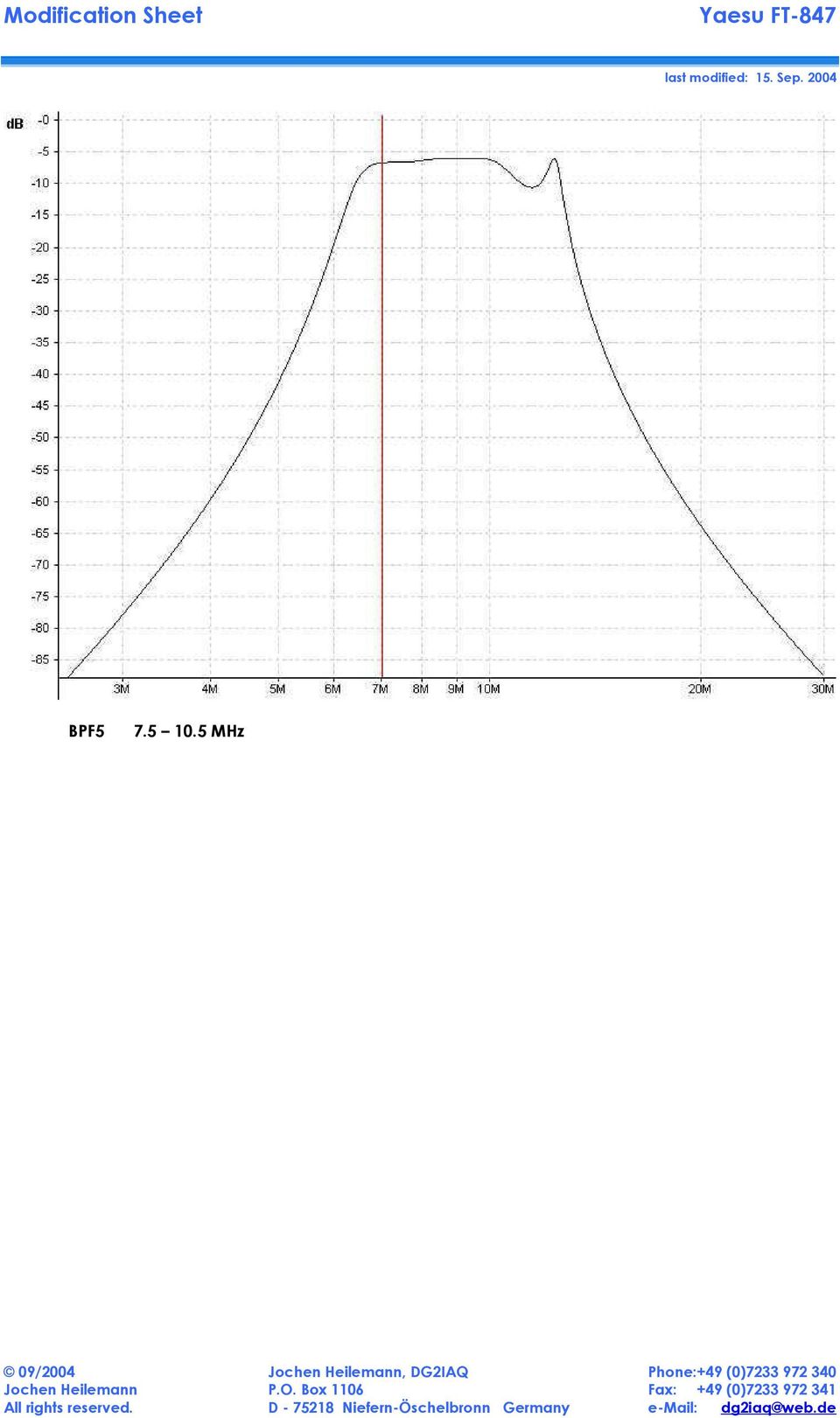
16 RX Bandpass Filters Then I checked the several RX bandpass filters with my electronic program and recognized, that the filter curves work well for the necessary band areas they re designed for. No need to modify them. I have read an earlier article that you do have to modify some bandpass filters on an old Yaesu FT- 747GX to get them correctly back on the several HAM radio bands. The bandpass filters in the FT-847 are well designed and really flat in their passband range.. BPF MHz

17 BPF MHz

18 BPF MHz

19 BPF MHz

20 BPF MHz
21 BPF MHz
22 BPF MHz
23 BPF MHz
24 BPFA MHz This filter could be optimized
25 BPFA MHz (optimized) green curve original bandpass black curve optimized bandpass Modifications: C3265 (18pF) 22pF C3297 (18pF) 22pF C3277 (220pF) 180pF I don t need this band so I didn t do that modification. All plots are designed and printed by WIN-Elektronik v3.1 (
26 DSP NR menu #11 alignment I did several tests on SSB/FM modes. On conclusion I set the menu to 11 to get best results on all modes. The factory presetting of 7 was only useable on FM but has no difference on SSB mode. Values of 8 or more make improvements on both AM/FM and SSB and reduce white noise significant. range: 0-15 factory setting: 7 my used setting: 11
27 Miscellaneous You can find my own discovered mods here in this modification sheet. But I did some other mods for my FT-847 too, e.g. the af pa step mod. These still documented mods you can find on / Yaesu / FT-847
28 Disclaimer Disclaimer of liability This modifications mostly need to be done by a electronic specialist who had enough practise and who has knowledge in SMD soldering. You do the modifications on your own risk! Radio modifications shown here are provided for properly licensed operators only! The user is solely responsible for making sure that any modifications made to the radio unit must meet all Federal and State Regulations or the Country of use! Liability of damages to any equipment is the sole responsibility of the user! Downloading, viewing, or using any information provided on these pages automatically accepts the user to the terms of this agreement! Modifications are provided for information purposes only! Although the greatest care has been taken while compiling these documents, we cannot guarantee that the instructions will work on every radio presented. Copyright The author intended not to use any copyrighted material for the publication or, if not possible, to indicate the copyright of the respective object. The copyright for any material created by the author is reserved. Any duplication or use of objects such as diagrams, sounds or texts in other electronic or printed publications is not permitted without the author's agreement. Some circuit details are password-protected because of legal reasons. Please contact me via . If your company would like to provide technical information to be featured on this pages please contact me at: dg2iaq@web.de
Introduction. So this and all of my Modification Sheet are for education purposes only!
 Introduction I started on doing modifications of CB- and HAM-radios since 1980 at the age of 12 years. I mostly wasn t satisfied with the sound of the modulation or reception of my rigs. This is normally
So this and all of my Modification Sheet are for education purposes only!
 Introduction I started on doing modifications of CB- and HAM-radios since 1980 at the age of 12 years. I mostly wasn t satisfied with the sound of the modulation or reception of my rigs. This is normally
Jochen Heilemann (DG2IAQ) German Amateur Radio Station. Yaesu FT-7100M Version 1.4. VHF/UHF Duoband Transceiver
 German Amateur Radio Station. Yaesu FT-7100M Version 1.4. VHF/UHF Duoband Transceiver") Introduction I started on doing modifications of CB- and HAM-radios since 1980 at the age of 12 years. I mostly wasn t satisfied with the sound of the modulation or reception of my rigs. This is normally
Introduction I started on doing modifications of CB- and HAM-radios since 1980 at the age of 12 years. I mostly wasn t satisfied with the sound of the modulation or reception of my rigs. This is normally
Directory. last modified: 27. Dez. 2004
 Directory Introduction...2 Some background informations about the FT-897 mods...3 FT-897 FT-857...3 AGC...3 Speechprocessor...3 ALC audio pumping...5 Exciter Stage Protection...6 Proper BIAS-adjustment...7
MAINTENANCE & ADJUSTMENT
 MAINTENANCE & ADJUSTMENT Circuit Theory The concept of PLL system frequency synthesization is not of recent development, however, it has not been a long age since the digital theory has been couplet with
Homebuilt HF Radios for Use Underground Paul R. Jorgenson KE7HR
 Homebuilt HF Radios for Use Underground Paul R. Jorgenson KE7HR With the good success in using Amateur Band HF radio for underground communications, I started looking for cheaper alternatives to the $500+
Modifying the Yaesu FT-847 External 22.625 MHz Reference Input
 Modifying the Yaesu FT-847 External 22.625 MHz Reference Input David Smith VK3HZ Introduction This document describes the modification of an FT-847 to allow an external 22.625 MHz Reference oscillator
Audio processing and ALC in the FT-897D
 Audio processing and ALC in the FT-897D I recently bought an FT-897D, and after a period of operation noticed problems with what I perceived to be a low average level of output power and reports of muffled
AM TRANSMITTERS & RECEIVERS
 Reading 30 Ron Bertrand VK2DQ http://www.radioelectronicschool.com AM TRANSMITTERS & RECEIVERS Revision: our definition of amplitude modulation. Amplitude modulation is when the modulating audio is combined
Amplifier for Small Magnetic and Electric Wideband Receiving Antennas (model AAA-1B)
") Amplifier for Small Magnetic and Electric Wideband Receiving Antennas (model AAA-1B) 1. Description and Specifications Contents 1.1 Description 1.2 1.2 Specifications 1.3 1.3 Tested parameters in production
Amplifier for Small Magnetic and Electric Wideband Receiving Antennas (model AAA-1B) 1. Description and Specifications Contents 1.1 Description 1.2 1.2 Specifications 1.3 1.3 Tested parameters in production
Yaesu FT-847 70mhz Pre-amplifier
 Yaesu FT-847 70mhz Pre-amplifier By CT1FFU- Tony I decided to buy a Yaesu FT-847. Using an all mode all band radio, operation becomes much easier and give better accommodation on shack however, I soon
Germanium Diode AM Radio
 Germanium Diode AM Radio LAB 3 3.1 Introduction In this laboratory exercise you will build a germanium diode based AM (Medium Wave) radio. Earliest radios used simple diode detector circuits. The diodes
Alpha 10 SERVICE MANUAL. Downloaded from www.cbradio.nl. MAX 10 Meter Amateur Transceiver AM/FM/CW/SSB 6 BAND PROGRAMMABLE MODEL AM-1000.
 Alpha 10 MAX 10 Meter Amateur Transceiver MODEL AM-1000 AM/FM/CW/SSB 6 BAND PROGRAMMABLE SERVICE MANUAL Downloaded from www.cbradio.nl Cover Page LOUDER TALKBACK MOD Alpha 10 Max - Model AM-1000 4.7K Resistor
Kit 106. 50 Watt Audio Amplifier
 Kit 106 50 Watt Audio Amplifier T his kit is based on an amazing IC amplifier module from ST Electronics, the TDA7294 It is intended for use as a high quality audio class AB amplifier in hi-fi applications
Application Note Receiving HF Signals with a USRP Device Ettus Research
 Application Note Receiving HF Signals with a USRP Device Ettus Research Introduction The electromagnetic (EM) spectrum between 3 and 30 MHz is commonly referred to as the HF band. Due to the propagation
A CW QRP Transceiver for 20 m band. How it works I'll describe individually the three boards and the relative tuning devices.
 A CW QRP Transceiver for 20 m band The little QRP presented in this article may be built in a gradual manner, in fact it is divided in two main modules (plus VFO), you may also complete only a single part
Without the pre amp, these microphones sound very good with tube equipment that provided a very high impedance load to the element.
 N9WB D-104 Project Revision 2 Pre Amp Modifications for higher load impedance. By Walter A. Breining, N9WB D-104 Discussion The D-104 has been around since the 30 s and is still popular today for communications.
Modification Details.
 Front end receiver modification for DRM: AKD Target Communications receiver. Model HF3. Summary. The receiver was modified and capable of receiving DRM, but performance was limited by the phase noise from
Single Transistor FM Transmitter Design
 Single Transistor FM Transmitter Design In telecommunications, frequency modulation (FM) conveys information over a carrier wave by varying its frequency. FM is commonly used at VHF radio frequencies for
THE R551N RECEIVER FAQ FAULT FINDING THE REDIFON COMMUNICATIONS RECEIVER R551N. Date: October 10th 1995 by: Jan Verduyn G5BBL
 THE R551N RECEIVER FAQ FAULT FINDING THE REDIFON COMMUNICATIONS RECEIVER R551N Introduction: Date: October 10th 1995 by: Jan Verduyn G5BBL Recently a number of Redifon R551N receivers have appeared on
The front end of the receiver performs the frequency translation, channel selection and amplification of the signal.
 Many receivers must be capable of handling a very wide range of signal powers at the input while still producing the correct output. This must be done in the presence of noise and interference which occasionally
Assembly Instructions: Shortwave Radio Kit
 Assembly Instructions: Shortwave Radio Kit MTM Scientific, Inc P.O. Box 522 Clinton, MI 49236 U.S.A Introduction Fig 1: The assembled Shortwave Radio Kit The SHORTWAVE RADIO KIT (#SWRAD) from MTM Scientific
DX 2517. AM FM SSB CW PA Amateur Base Station Transceiver OWNER S MANUAL RX / TX 2 4 POWER NF CHANNEL MODE RF POWER OFF CAL OFF OFF CALIBRATE
 1 2 3 6 4050 ULA 6070 TI 80 90 100 9 DX 2517 2517 RX / TX 0 2 4 SWR WATTS SET 81012 22 1 010 3 2030 5 MOD 7 ON dbover 9 SIGNAL +20 +40+60 PA FM AM USB LSB CW POWER ON SWR NB / ANL R.BEEP +10KHz NF CHANNEL
TROUBLESHOOTING RECEIVERS
 TROUBLESHOOTING RECEIVERS The four methods of troubleshooting are: 1. Circuit Disturbance 2. Signal Substitution 3. Signal Tracing 4. Measurement of Circuit Parameters Definition of Terms: Circuit Disturbance
The RSGB Centenary Receiver Project Construction Manual
 The RSGB Centenary Receiver Project Construction Manual Page 1 of 12 Introduction This project is intended for those new to radio construction. It is a fairly simple receiver for the 14MHz (20m) amateur
FILTERS - IN RADIO COMMUNICATIONS
 Reading 32 Ron Bertrand VK2DQ http://www.radioelectronicschool.com FILTERS - IN RADIO COMMUNICATIONS RADIO SIGNALS In radio communications we talk a lot about radio signals. A radio signal is a very broad
The FT-1000MP, MK V and Field: Filter Selection and Modification Guide
 The FT-1000MP, MK V and Field: Filter Selection and Modification Guide www.inrad.net Copyright International Radio Corporation, Revised Jan 30, 2008 1 The FT-1000MP receiver is triple conversion, with
Yaesu FT-847 70 MHz PA output and filter simulations Marc Vlemmings, PA1O - Eindhoven, The Netherlands
 Yaesu FT-847 70 MHz PA output and filter simulations Marc Vlemmings, PA1O - Eindhoven, The Netherlands The efficiency of the HF transmitter chain which is also used for 50 MHz and 70 MHz decreases with
HP 8970B Option 020. Service Manual Supplement
 HP 8970B Option 020 Service Manual Supplement Service Manual Supplement HP 8970B Option 020 HP Part no. 08970-90115 Edition 1 May 1998 UNIX is a registered trademark of AT&T in the USA and other countries.
Owner s Manual 900.4. 4 channel amplifier
 Owner s Manual 900.4 4 channel amplifier THANK YOU Limited Warranty: for purchasing RE AUDIO Bluetooth amplifiers BT-900.4. With almost no sacrifice on sound quality, BT-900.4 easily plays the music from
www.fmtalkinghouse.com
 www.fmtalkinghouse.com 24x7 FM Announcement System (Talking Sign) 2009 FM TALKING HOUSE All rights reserved Talking Sign 24x7 FM Announcement System Description: The 24x7 FM Announcement System or Talking
K2 CW Filter Alignment Procedures Using Spectrogram 1 ver. 5 01/17/2002
 K2 CW Filter Alignment Procedures Using Spectrogram 1 ver. 5 01/17/2002 It will be assumed that you have already performed the RX alignment procedures in the K2 manual, that you have already selected the
DRM compatible RF Tuner Unit DRT1
 FEATURES DRM compatible RF Tuner Unit DRT1 High- Performance RF Tuner Frequency Range: 10 KHz to 30 MHz Input ICP3: +13,5dBm, typ. Noise Figure @ full gain: 14dB, typ. Receiver Factor: -0,5dB, typ. Input
Introduction to Receivers
 Introduction to Receivers Purpose: translate RF signals to baseband Shift frequency Amplify Filter Demodulate Why is this a challenge? Interference (selectivity, images and distortion) Large dynamic range
SUPER SNOOPER BIG EAR
 AA-1D Super Snooper Big Ear SPECIFICATIONS Operates on 5 to 9v DC Will drive a small speaker Provides up to 1 watt of audio power Distortion > 0.2% Voltage Gain up to 46 db Size: 1 x 1.95 Rainbowkits.com
PGA103+ Low noise, high dynamic range preamp for VHF and UHF
 PGA103+ Low noise, high dynamic range preamp for VHF and UHF By Sam Jewell, G4DDK and Kent Britain, WA5VJB Introduction This paper describes a low noise, high dynamic range VHF/UHF preamp that uses the
Understanding the DriveRack PA. The diagram below shows the DriveRack PA in the signal chain of a typical sound system.
 Understanding the DriveRack PA The diagram below shows the DriveRack PA in the signal chain of a typical sound system. The diagram below shows all the pieces within a sound system that the DriveRack PA
Youkits TJ2B 2016 SSB CW HF TRANSCEIVER OPERATION GUIDE
 Youkits TJ2B 2016 SSB CW HF TRANSCEIVER OPERATION GUIDE TJ2B is a high-performance QRP portable multi-band SSB/CW transceiver, used with DDS as LO, offering wide frequency coverage and fine tuning rate.
One Stage Superheterodyne Receiver with the SA602N integrated Circuit
 One Stage Superheterodyne Receiver with the SA602N integrated Circuit If you ever dreamt of building a superheterodyne receiver, now you have the possibility of bringing to reality...your dream! And this
PS 155 WIRELESS INTERCOM USER MANUAL
 PS 155 INTERFACE TO SIMPLEX WIRELESS INTERCOM USER MANUAL Issue 2011 ASL Intercom BV DESIGNED AND MANUFACTURED BY: ASL INTERCOM BV ZONNEBAAN 42 3542 EG UTRECHT THE NETHERLANDS PHONE: +31 (0)30 2411901
Ameritron ATP-102 Tuning Pulser II
 Ameritron ATP-102 The Ameritron ATP-102 relieves temperature related stress on amplifiers, tuners, and dummy loads while allowing proper system adjustments. It allows amplifiers to be properly adjusted
Cumbria Designs T-1. SSB/CW Filter kit (4.9152MHz) User Manual
 User Manual") Cumbria Designs T-1 SSB/CW Filter kit (4.9152MHz) User Manual CONTENTS 1 INTRODUCTION 2 2 CIRCUIT DESCRIPTION 2 3 ASSEMBLY 2 4 TESTING 4 The Steading Stainton PENRITH Cumbria CA11 0ES UK 1 Introduction
Cumbria Designs T-1 SSB/CW Filter kit (4.9152MHz) User Manual CONTENTS 1 INTRODUCTION 2 2 CIRCUIT DESCRIPTION 2 3 ASSEMBLY 2 4 TESTING 4 The Steading Stainton PENRITH Cumbria CA11 0ES UK 1 Introduction
The basic set up for your K2 to run PSK31 By Glenn Maclean WA7SPY
 The basic set up for your K2 to run PSK31 By Glenn Maclean WA7SPY I am by no means an expert on PSK31. This article is intended to help someone get on PSK31 with a K2. These are the things I did to get
November 1995 QST Volume 79, Number 11
 Lab Notes Prepared by the ARRL Laboratory Staff (e-mail: tis@arrl.org) ELECTRONIC TROUBLESHOOTING By Ed Hare, KA1CV, ARRL Laboratory Supervisor Q: Someone just gave me a collection of used amateur equipment,
TS-480HX/TS-480SAT. HF/50MHz All-Mode Transceiver KENWOOD. NETWORK COMMAND SYSTEM with Voice over Internet Protocol capability
 TS-480HX/TS-480SAT HF/50MHz All-Mode Transceiver KENWOOD NETWORK COMMAND SYSTEM with Voice over Internet Protocol capability DX Distinction Creative Concept, Elegant Engineering 200W output (50MHz: 100W)
PIEZO FILTERS INTRODUCTION
 For more than two decades, ceramic filter technology has been instrumental in the proliferation of solid state electronics. A view of the future reveals that even greater expectations will be placed on
DX 88HL OWNER S MANUAL. Full Channel AM/FM/SSB Mobile Built in Frequency Counter AM/FM 10W SSB 25W with Roger Beep
 DX 88HL Full Channel AM/FM/SSB Mobile Built in Frequency Counter AM/FM 10W SSB 25W with Roger Beep Printed In Malaysia AT2100013P PD000929 OWNER S MANUAL TABLE OF CONTENTS Page Specification...................................
VHF COMMUNICATION TRANSCEIVER
 ATR-500 VHF COMMUNICATION TRANSCEIVER ON OFF OPERATION MANUAL Manual Number 01.125.010.08 REVISION 1.3, Jan 20. 2005 from S/N 00301 04 Contents 1 SECTION 1 GENERAL INFORMATION...3 1.1 INTRODUCTION...3
All rights reserved, project are free only for personal use
 HAM Sample and Hold SDR (Software Defined Radio) Receiver for SSB,CW,AM,FM, DRM..On HF (30 khz to 70 MHz) in Connection With PC Sound Card Make it Simple as Possible with Outstanding Performances Part
Routinely DIYers opt to make themselves a passive preamp - just an input selector and a volume control.
 The First Watt B1 Buffer Preamp Nelson Pass, June 2008 Side A So here we are in the New Millennium, and thanks to Tom Holman and THX we ve got lots of gain in our electronics. More gain than some of us
An Adjustable Audio Filter System for the Receiver - Part 1
 1 of 7 An Adjustable Audio Filter System for the Receiver - Part 1 The audio response is shaped as required using Switched Capacitor Filters Lloyd Butler VK5BR Front panel view of the original receiver
VOLUME AND TONE CONTROL - PREAMPLIFIER K8084
 H8084IP-1 VOLUME AND TONE CONTROL - PREAMPLIFIER K8084 When using one of our amplifiers (big or small), you always need a volume control and preferably also a tone control Features & specifications When
DAB1001. Wireless Digital Radio Interface. Installation & User Guide
 DAB1001 Wireless Digital Radio Interface Installation & User Guide Contents Contents... 2 Introduction... 3 Contents of Package... 4 Installation... 5 Product Overview... 5 Installation Procedure... 5
PS 29M DUAL CHANNEL BELTPACK IN METAL CASE
 PS 29M DUAL CHANNEL BELTPACK IN METAL CASE USER MANUAL October 2013 This product is designed and manufactured by: ASL Intercom BV Zonnebaan 42 3542 EG Utrecht The Netherlands Phone: +31 (0)30 2411901 Fax:
Glolab Talking Phone Dial Monitor
 Introduction The detects the tones generated when numbers are dialed on your touch tone telephone and speaks the numbers that were dialed. This verifies that you dialed the correct number and is especially
HF to LF/MF Linear Transverter with 500kHz Class D EER Power Amplifier
 HF to LF/MF Linear Transverter with 500kHz Class D EER Power Amplifier Jim Moritz, M0BMU, 4 th November 2007 Fig 1 EER Transverter System The transverter board is on top of the IC718 HF transceiver; the
MATRIX TECHNICAL NOTES
 200 WOOD AVENUE, MIDDLESEX, NJ 08846 PHONE (732) 469-9510 FAX (732) 469-0418 MATRIX TECHNICAL NOTES MTN-107 TEST SETUP FOR THE MEASUREMENT OF X-MOD, CTB, AND CSO USING A MEAN SQUARE CIRCUIT AS A DETECTOR
Operation Manual for Users
 Operation Manual for Users Model No.: FLTAMFMRCD!!!!!!!!!! ATTENTION!!!!!!!!!! THE RESET BUTTON MUST BE PRESSED TO ENSURE PROPER OPERATION. SEE INSTRUCTION MANUAL Table of Contents Table of Contents ---------------------------------------------------------------------------------------------
TELIKOU Intercom System. MS-500(4+1 channel) Main Station Instruction Manual
 Main Station Instruction Manual") TELIKOU Intercom System MS-500(4+1 channel) Main Station Instruction Manual TELIKOU Systems All Rights Reserved While TELIKOU makes every attempt to maintain the accuracy of the information contained in
TELIKOU Intercom System MS-500(4+1 channel) Main Station Instruction Manual TELIKOU Systems All Rights Reserved While TELIKOU makes every attempt to maintain the accuracy of the information contained in
Build a Voltage and Current Peak Detector
 ax You Can DIY! Build a Voltage and Current Peak Detector Here is a simple portable device that can help answer the question about peak voltage and peak current requirements and whether or not your power
Simple SDR Receiver. Looking for some hardware to learn about SDR? This project may be just what you need to explore this hot topic!
 Michael Hightower, KF6SJ 13620 White Rock Station Rd, Poway, CA 92064; kf6sj@arrl.net Simple SDR Receiver Looking for some hardware to learn about SDR? This project may be just what you need to explore
Features. Applications. Transmitter. Receiver. General Description MINIATURE MODULE. QM MODULATION OPTIMAL RANGE 1000m
 Features MINIATURE MODULE QM MODULATION OPTIMAL RANGE 1000m 433.05 434.79 ISM BAND 34 CHANNELS AVAILABLE SINGLE SUPPLY VOLTAGE Applications IN VEHICLE TELEMETRY SYSTEMS WIRELESS NETWORKING DOMESTIC AND
A PIC16F628 controlled FLL (Frequency Locked Loop) VFO for HF
 VFO for HF") Abstract A PI6F628 controlled FLL (Frequency Locked Loop) VFO for HF It is described a device which joins in a single microprocessor a digital programmable frequency meter and a control logic capable to
Abstract A PI6F628 controlled FLL (Frequency Locked Loop) VFO for HF It is described a device which joins in a single microprocessor a digital programmable frequency meter and a control logic capable to
PGA103+ Low noise, high dynamic range preamp for VHF and UHF
 PGA103+ Low noise, high dynamic range preamp for VHF and UHF By Sam Jewell, G4DDK and Kent Britain, WA5VJB Introduction The PGA103+ from MCL achieves sub 0.5dB noise figure (NF) at 144MHz and better than
DDX 7000 & 8003. Digital Partial Discharge Detectors FEATURES APPLICATIONS
 DDX 7000 & 8003 Digital Partial Discharge Detectors The HAEFELY HIPOTRONICS DDX Digital Partial Discharge Detector offers the high accuracy and flexibility of digital technology, plus the real-time display
Tire pressure monitoring
 Application Note AN601 Tire pressure monitoring 1 Purpose This document is intended to give hints on how to use the Intersema pressure sensors in a low cost tire pressure monitoring system (TPMS). 2 Introduction
DL-QRP-AG Lambda/2 no Counterpoise: Fuchs Antenna matching unit
 DL-QRP-AG Lambda/2 no Counterpoise: Fuchs Antenna matching unit QRPproject Molchstr. 15 12524 Berlin http://www.qrpproject.de Telefon: +49(30) 85 96 13 23 e-mail: support@qrpproject.de Handbucherstellung:
RigExpert AA-30 Antenna Analyzer (0.1 to 30 MHz) AA-54 Antenna Analyzer (0.1 to 54 MHz) User s manual
 AA-54 Antenna Analyzer (0.1 to 54 MHz) User s manual") RigExpert AA-30 Antenna Analyzer (0.1 to 30 MHz) AA-54 Antenna Analyzer (0.1 to 54 MHz) User s manual Table of contents 1. Description... 3 2. Specifications... 4 3. Precautions... 5 4. Operation... 6
RigExpert AA-30 Antenna Analyzer (0.1 to 30 MHz) AA-54 Antenna Analyzer (0.1 to 54 MHz) User s manual Table of contents 1. Description... 3 2. Specifications... 4 3. Precautions... 5 4. Operation... 6
LR Phono Preamps. Pete Millett ETF.13. pmillett@hotmail.com
 LR Phono Preamps Pete Millett ETF.13 pmillett@hotmail.com Agenda A bit about me Part 1: What is, and why use, RIAA? Grooves on records The RIAA standard Implementations of RIAA EQ networks and preamps
K8025 VIDEO PATTERN GENERATOR. Check the picture quality of your monitor or TV, ideal for adjustment or troubleshooting.
 K8025 ILLUSTRATED ASSEMBLY MANUAL H8025IP 1 VIDEO PATTERN GENERATOR Check the picture quality of your monitor or TV, ideal for adjustment or troubleshooting. Forum Participate our Velleman Projects Forum
CX Zoner Installation & User Guide
 CX Zoner Installation & User Guide Cloud Electronics Limited 140 Staniforth Road, Sheffield, S9 3HF England Tel +44 (0)114 244 7051 Fax +44 (0)114 242 5462 e-mail info@cloud.co.uk web site http://www.cloud.co.uk
Total solder points: 167 Difficulty level: beginner 1 2 3 4 5 advanced DMX CONTROLLED RELAY K8072 ILLUSTRATED ASSEMBLY MANUAL
 Total solder points: 167 Difficulty level: beginner 1 2 3 4 5 advanced DMX CONTROLLED RELAY K8072 Control a relay by means of the wellknown DMX512 protocol. ILLUSTRATED ASSEMBLY MANUAL H8072IP-1 Features
K6002 TEMPERATURE CONTROLLER. Specifications
 Total solder points: 169 + 99 + 67 Difficulty level: beginner 1 2 3 4 5 advanced TEMPERATURE CONTROLLER K6002 Unlike a normal thermostat, this kit has two outputs, one for "high" alarm and one for "low"
OPTIMA MK2 OWNERS MANUAL & USER GUIDE. Downloaded from www.cbradio.nl. 24.500 29.999 Mhz 50W All Mode HF Mobile Transceiver
 OPTIMA MK2 OWNERS MANUAL & USER GUIDE Downloaded from www.cbradio.nl 24.500 29.999 Mhz 50W All Mode HF Mobile Transceiver (February 2012 production) REV 1.61 Copyright January 2012 by YeticomNZ. All rights
CONDUCTED EMISSION MEASUREMENT OF A CELL PHONE PROCESSOR MODULE
 Progress In Electromagnetics esearch C, Vol. 42, 191 203, 2013 CONDUCTED EMISSION MEASUEMENT OF A CELL PHONE POCESSO MODULE Fayu Wan *, Junxiang Ge, and Mengxiang Qu Nanjing University of Information Science
CONTENTS. Zulu User Guide 3
 Copyright Lightspeed Aviation, Inc., 2008. All rights reserved. Lightspeed Aviation is a trademark and Zulu and FRC are registered trademarks of Lightspeed Aviation, Inc. Bluetooth is a registered trademark
Installation & Operation Manual HANDS-FREE BLUETOOTH MEDIA INTEGRATION KIT. Perfect for ANDROID TM
 GET CONNECTED Installation & Operation Manual HANDS-FREE BLUETOOTH MEDIA INTEGRATION KIT TranzIt BLU HF ISFM2351 Perfect for ANDROID TM Note to Readers, The information contained within the following documentation
Department of Electrical and Computer Engineering Ben-Gurion University of the Negev. LAB 1 - Introduction to USRP
 Department of Electrical and Computer Engineering Ben-Gurion University of the Negev LAB 1 - Introduction to USRP - 1-1 Introduction In this lab you will use software reconfigurable RF hardware from National
INTEGRATED CIRCUITS DATA SHEET. TDA7000 FM radio circuit. Product specification File under Integrated Circuits, IC01
 INTEGRATED CIRCUITS DATA SHEET File under Integrated Circuits, IC01 May 1992 GENERAL DESCRIPTION The is a monolithic integrated circuit for mono FM portable radios, where a minimum on peripheral components
SP1790JK 900MHz Wireless Indoor/Outdoor Speakers. User Manual INTRODUCTION FEATURES IMPORTANT SAFETY INFORMATION
 SP1790JK 900MHz Wireless Indoor/Outdoor Speakers INTRODUCTION This 900 MHz digital hybrid wireless speaker system uses the latest wireless technology that enables you to enjoy music and TV sound anywhere
Turbo X. www.smartwireless.co.uk. 594 channel UHF true diversity
 Turbo X 594 channel UHF true diversity The new Turbo X series from Smart Wireless is the culmination of two years of research and development into advanced wireless technology. Using sophisticated RF design
User Manual. Please read this manual carefully before using the Phoenix Octopus
 User Manual Please read this manual carefully before using the Phoenix Octopus For additional help and updates, refer to our website To contact Phoenix Audio for support, please send a detailed e-mail
LM 358 Op Amp. If you have small signals and need a more useful reading we could amplify it using the op amp, this is commonly used in sensors.
 LM 358 Op Amp S k i l l L e v e l : I n t e r m e d i a t e OVERVIEW The LM 358 is a duel single supply operational amplifier. As it is a single supply it eliminates the need for a duel power supply, thus
DT3: RF On/Off Remote Control Technology. Rodney Singleton Joe Larsen Luis Garcia Rafael Ocampo Mike Moulton Eric Hatch
 DT3: RF On/Off Remote Control Technology Rodney Singleton Joe Larsen Luis Garcia Rafael Ocampo Mike Moulton Eric Hatch Agenda Radio Frequency Overview Frequency Selection Signals Methods Modulation Methods
Kenwood introduces. new HF/50MHz All-Mode Transceiver
 New Product Release Information Oct 2014 TS-590SG HF/ 50MHz All-Mode TRANSCEIVER_ Kenwood introduces Updated to new G version new HF/50MHz All-Mode Transceiver Four years ago we launched our best-selling
GUITAR PREAMPLIFIER WITH HEADPHONE OUTPUT K4102
 H4102IP-1 GUITAR PREAMPLIFIER WITH HEADPHONE OUTPUT K4102 Practice the guitar without disturbing others. Features & Specifications Features: An electric guitar cannot be connected to just any amplifier
Design and Certification of ASH Radio Systems for Japan
 Design and Certification of ASH Radio Systems for Japan RFM s second-generation ASH radio hybrids are being used in a wide variety of applications in Japan, operating under the Japanese BIJAKU radio regulations.
Chapter 19 Operational Amplifiers
 Chapter 19 Operational Amplifiers The operational amplifier, or op-amp, is a basic building block of modern electronics. Op-amps date back to the early days of vacuum tubes, but they only became common
USER GUIDE PRO-EQ PLATINUM
 USER GUIDE PRO-EQ PLATINUM Welcome Thank you for making Fishman a part of your acoustic experience. We are proud to offer the finest acoustic amplification products available: high-quality professional-grade
The new Velleman Projects catalogue is now available. Download your copy here: www.vellemanprojects.eu
 The new Velleman Projects catalogue is now available. Download your copy here: www.vellemanprojects.eu Modifications and typographical errors reserved - Velleman nv. H8098 IP 2 (rev.1.0) Velleman NV, Legen
THE MclNTOSH MC 2100 SOLID STATE STEREO POWER AMPLIFIER
 THE MclNTOSH MC 2100 SOLID STATE STEREO POWER AMPLIFIER Price $1.25 Your MC 2100 stereo amplifier will give you many years of pleasant and satisfactory performance. If you have any questions concerning
VoiceTone T1 USER S MANUAL
 VoiceTone T1 USER S MANUAL Important Safety Instructions 1 Read these instructions. 2 Keep these instructions. 3 Heed all warnings. 4 Follow all instructions. 5 Do not use this apparatus near water. 6
POCKET AUDIO GENERATOR K8065
 POCKET AUDIO GENERATOR K8065 Great little gadget for service repair, testing, education, etc... ILLUSTRATED ASSEMBLY MANUAL H8065IP-1 VELLEMAN NV Legen Heirweg 33 9890 Gavere Belgium Europe www.velleman.be
Power Management and Battery Performance for the FTD1 and FT2D
 Power Management and Battery Performance for the FTD1 and FT2D This document discusses how power is used in the FT1D and FT2D HT s so that you can better optimize your radio s configuration to get the
Modulation Methods SSB and DSB
 Modulation Methods SSB and DSB William Sheets K2MQJ Rudolf F. Graf KA2CWL SSB or Single Sideband, is a type of AM without the carrier and one sideband. DSB or double sideband is AM with the carrier suppressed,
TEACHING RESOURCES SCHEMES OF WORK DEVELOPING A SPECIFICATION COMPONENT FACTSHEETS HOW TO SOLDER GUIDE GET IN TUNE WITH THIS FM RADIO KIT. Version 2.
 TEACHING RESOURCES SCHEMES OF WORK DEVELOPING A SPECIFICATION COMPONENT FACTSHEETS HOW TO SOLDER GUIDE GET IN TUNE WITH THIS FM RADIO KIT Version 2.0 Index of Sheets TEACHING RESOURCES Index of Sheets
Study of RF Spectrum Emissions in High Pressure Sodium and Metal Halide Lamps. Lawrence P. Glaister VE7IT, Automation Engineer.
 Study of RF Spectrum Emissions in High Pressure Sodium and Metal Halide Lamps Lawrence P. Glaister VE7IT, Automation Engineer May 2010 Abstract: This research was performed in collaboration with the City
Power Supply V- Bonding, Hum, Buzz, and RFI Should We Bond V- at the Power Supply or Not? Jim Brown K9YC
 Power Supply V- Bonding, Hum, Buzz, and RFI Should We Bond V- at the Power Supply or Not? Jim Brown K9YC I've seen numerous anecdotal comments suggesting that all might not be right with the grounding
DDX 7000 & 8003. Digital Partial Discharge Detectors FEATURES APPLICATIONS
 DDX 7000 & 8003 Digital Partial Discharge Detectors The HAEFELY HIPOTRONICS DDX Digital Partial Discharge Detector offers the high accuracy and flexibility of digital technology, plus the real-time display
INSTRUCTION MANUAL PLEASE READ ALL THE INSTRUCTIONS COMPLETELY BEFORE USE AND SAVE THIS MANUAL FOR FUTURE REFERENCE
 INSTRUCTION MANUAL PLEASE READ ALL THE INSTRUCTIONS COMPLETELY BEFORE USE Ver. 2.0 AND SAVE THIS MANUAL FOR FUTURE REFERENCE Table of Contents Unpacking... 3 About the CCRadio-EP... 4 Quick Start Guide...